

Page 1
OSMAC®Base Station
Digital Wireless Paging System
User’s Guide
Installation
Programming
Operation
Commands
Page 2

Page 3

1
TABLE OF CONTENTS
Introduction . . . . . . . . . . . . . . . . . . . . . . . . . . . . . . . . . . . . . . . . . . . . . . . . . . . . . . . . . . . . . . . . . . . . . .2
System Overview
. . . . . . . . . . . . . . . . . . . . . . . . . . . . . . . . . . . . . . . . . . . . . . . . . . . . . . . . . . . . . .2
Display/Indicators
. . . . . . . . . . . . . . . . . . . . . . . . . . . . . . . . . . . . . . . . . . . . . . . . . . . . . . . . . . . . .3
Keypad
. . . . . . . . . . . . . . . . . . . . . . . . . . . . . . . . . . . . . . . . . . . . . . . . . . . . . . . . . . . . . . . . . . . . .3
Sending A Satellite Command
. . . . . . . . . . . . . . . . . . . . . . . . . . . . . . . . . . . . . . . . . . . . . . . . . . . . .3
Rear Panel Connections
. . . . . . . . . . . . . . . . . . . . . . . . . . . . . . . . . . . . . . . . . . . . . . . . . . . . . . . . .4
Installation . . . . . . . . . . . . . . . . . . . . . . . . . . . . . . . . . . . . . . . . . . . . . . . . . . . . . . . . . . . . . . . . . . . . . . .5
Power Supply Connection
. . . . . . . . . . . . . . . . . . . . . . . . . . . . . . . . . . . . . . . . . . . . . . . . . . . . . . .5
Antenna Connections
. . . . . . . . . . . . . . . . . . . . . . . . . . . . . . . . . . . . . . . . . . . . . . . . . . . . . . . . . . .5
SitePro
TM
Setup . . . . . . . . . . . . . . . . . . . . . . . . . . . . . . . . . . . . . . . . . . . . . . . . . . . . . . . . . . . . . . .5
TouchNet
TM
Setup . . . . . . . . . . . . . . . . . . . . . . . . . . . . . . . . . . . . . . . . . . . . . . . . . . . . . . . . . . . . .5
Base Station Operation . . . . . . . . . . . . . . . . . . . . . . . . . . . . . . . . . . . . . . . . . . . . . . . . . . . . . . . . . . . . .6
Manual Operation Overview
. . . . . . . . . . . . . . . . . . . . . . . . . . . . . . . . . . . . . . . . . . . . . . . . . . . . . .6
Keypad Operation
. . . . . . . . . . . . . . . . . . . . . . . . . . . . . . . . . . . . . . . . . . . . . . . . . . . . . . . . . . . . .6
Hand Held Radio Operation
. . . . . . . . . . . . . . . . . . . . . . . . . . . . . . . . . . . . . . . . . . . . . . . . . . . . . .6
Telephone Operation
. . . . . . . . . . . . . . . . . . . . . . . . . . . . . . . . . . . . . . . . . . . . . . . . . . . . . . . . . . .7
Advanced Hand Held Radio Operation . . . . . . . . . . . . . . . . . . . . . . . . . . . . . . . . . . . . . . . . . . . . . . . .8
Placing Phone Calls From The Two-Way Radio
. . . . . . . . . . . . . . . . . . . . . . . . . . . . . . . . . . . . . . . .8
Autodial Memory
. . . . . . . . . . . . . . . . . . . . . . . . . . . . . . . . . . . . . . . . . . . . . . . . . . . . . . . . . . . . . .8
Receiving Phone Calls
. . . . . . . . . . . . . . . . . . . . . . . . . . . . . . . . . . . . . . . . . . . . . . . . . . . . . . . . .10
Program Mode . . . . . . . . . . . . . . . . . . . . . . . . . . . . . . . . . . . . . . . . . . . . . . . . . . . . . . . . . . . . . . . . . . .10
Assigning Satellite Address Number
. . . . . . . . . . . . . . . . . . . . . . . . . . . . . . . . . . . . . . . . . . . . . . .10
Assigning Satellite Groups
. . . . . . . . . . . . . . . . . . . . . . . . . . . . . . . . . . . . . . . . . . . . . . . . . . . . . .11
Sending Test Commands
. . . . . . . . . . . . . . . . . . . . . . . . . . . . . . . . . . . . . . . . . . . . . . . . . . . . . . .12
Alarm Commands
. . . . . . . . . . . . . . . . . . . . . . . . . . . . . . . . . . . . . . . . . . . . . . . . . . . . . . . . . . . .12
Autodial Memory
. . . . . . . . . . . . . . . . . . . . . . . . . . . . . . . . . . . . . . . . . . . . . . . . . . . . . . . . . . . . .13
Appendix A – OSMAC Configuration Commands . . . . . . . . . . . . . . . . . . . . . . . . . . . . . . . . . . . . . .14
Appendix B – Hand Held Radio Command Codes . . . . . . . . . . . . . . . . . . . . . . . . . . . . . . . . . . . . . .16
Specifications . . . . . . . . . . . . . . . . . . . . . . . . . . . . . . . . . . . . . . . . . . . . . . . . . . . . . . . . . . . . .Back Cover
Electromagnetic Compatibility Information . . . . . . . . . . . . . . . . . . . . . . . . . . . . . . . . . . . . .Back Cover
Page 4

2
INTRODUCTION
System Overview
The OSMAC Base Station is a desktop system that provides paging and wireless two-way communications. The base
station is equipped with a 32-bit Intel processor and 4 megabytes of flash memory. With such specification, the OSMAC
Base Station is capable of handling all the wireless paging and communication needs of a small field or a large golf
course.
OSMAC Base Station Features:
• Stand-alone operation with built-in keypad and Liquid Crystal Display (LCD)
• Built-in RS-232 serial port for central control applications
• Built-in telephone interface for remote access
• Internal two-way radio for monitoring the channel and two-way voice communication
• POCSAG paging encoder at 512 baud
• 1000 satellite database
• Group paging
• 8 external alarm inputs for automatic generation of pre-programmed commands
• Command codes may be initiated from DTMF equipped two-way radios
• Built-in speaker and microphone with provisions for external connections
The OSMAC Base Station is the command center for the E-OSMAC and current OSMAC Control Systems. Whether the
satellite commands are initiated automatically by the central computer or manually keyed by the user, all irrigation controls
are transmitted from the base station to the irrigation satellite by wireless paging system.
The OSMAC Base Station operates in one of two basic modes: Page Mode and Program Mode. The Page Mode is used
to send command codes to a selected satellite controller or group of satellites. The base station can also be used with a
two-way radio to communicate and send satellite commands. The Program Mode is used to program each individual
satellite information, group information, automatic paging information and some system-level features. Under normal circumstances, the system will be properly configured by the Toro distributor or field service representative during installation. Therefore, the user should not need to use the Program Mode.
Although the user can enter command codes using the built-in keypad, satellite commands can also be generated in a
variety of other ways. Satellite commands can be initiated from a computer using the base station’s built-in RS-232 serial
port located at the rear of the unit. A two-way radio with a DTMF keypad can also be used to transmit commands to
satellites. Another way to send satellite commands is to use a touch-tone phone which is connected to the built-in telephone interface. In addition, the base station can be configured to automatically generate command codes based upon
an electrical input from special an ALARMS port. The OSMAC Base Station is clearly one of the most versatile wireless
controllers on the market.
Note: Although the OSMAC Base Station is a functional replacement for the Motorola “People Finder,” it can not be used
as a direct substitute for the “People Finder.” The “People Finder” communicates in a language called “GOLAY”, which is
proprietary to Motorola. The new base station communicates in a similar language called “POCSAG”, but it is not recognized by current RDR-type field satellites. To utilize the new OSMAC Base Station with satellites from the old wide band
system, a new narrow band retrofit card and EPROM are required to be installed in each field satellite.
The OSMAC Base Station can be ordered in two receiving modes for hand-held communication. For current RDR sites
using Motorola GM-300 hand-held radios, wideband radio receiving can be ordered. For sites that are using Motorola
P1225 hand-held radios, narrow band receiving is recommended. Both base station models transmit commands to satellite controllers in narrow band to comply with the FCC regulations governing low-power users of the UHF band-width. If
you are uncertain about the type of base station needed, please contact your local Toro distributor or direct factory Field
Service Manager.
Caution: The FCC states that licensure of frequencies used by the base station and hand-held radios are the
responsibility of end-user. Unlicensed sites are subject to fines and prosecution under federal law.
Page 5

3
Display / Indicators
The OSMAC Base Station is equipped with a
two-line, twenty-character Liquid Crystal
Display (LCD). The three LEDs at the top right
corner of the unit indicate the current state of
the base station. The TRANSMIT indicator
illuminates while the base station is transmitting. The BUSY indicator illuminates while the
base station is receiving or processing data.
The PROGRAM indicator illuminates while the
base station is in the program mode. It is
possible for more than one indicator to illuminate at the same time.
Note: An LCD contrast adjustment screw,
located on the back of the unit, can be turned
with a small flat blade screwdriver. Turning the
screw clockwise or counter clockwise will darken or lighten the LCD characters.
Keypad
The built-in keypad is used in programming the
unit and manually entering command codes.
The OSMAC Base Station has a keypad buffer
that allows a user to type faster than the
prompt is able to display characters on the
screen. Keystrokes will not be lost and efficient
data entry is possible by operators skilled in
OSMAC Base Station operation.
The 16 keys have the following functions:
Sending a Satellite Command
The OSMAC Base Station waits for satellite address number input when the “PAGER NO =” prompt is displayed. Using
the keypad, enter the satellite address number you wish to send a command to. Once the satellite address number is
entered, press the F1 key to transmit.
The LCD will display “NUMERIC PAGER” for a second before it changes to “ENTER MESSAGE.” The user then enters
the desired command code into the display using the keypad. If the command code is longer than the length of the display, it will automatically scroll down to the next line as the command code is entered. Pressing the DEL key will delete
the previous character entered. Once the command code is entered, press the F1 key to transmit or wait for base station
to time-out to send automatically. The display will momentarily show “PAGE ACCEPTED” for a couple seconds and then
the display will return to the “PAGER NO=” prompt.
Note: For satellite command code procedure example, refer to the Keypad Operation information on page 6.
Key
0–9
F1
F2
F3
F4
DEL
– (Program)
VOL +/-
Primary Use
Entering numbers
Send a command after it is entered
Monitor the channel
Talk to a two-way radio
Send a tone-only command to
a numeric satellite
Correct an incorrect entry
Use as a dash (–) when entering
a command
Up/Down Arrow keys scroll through
various options on the display.
Adjust the local speaker volume
Secondary Use
Select sub-menu
Select options from the sub-menus
Enter mode and exist menus.
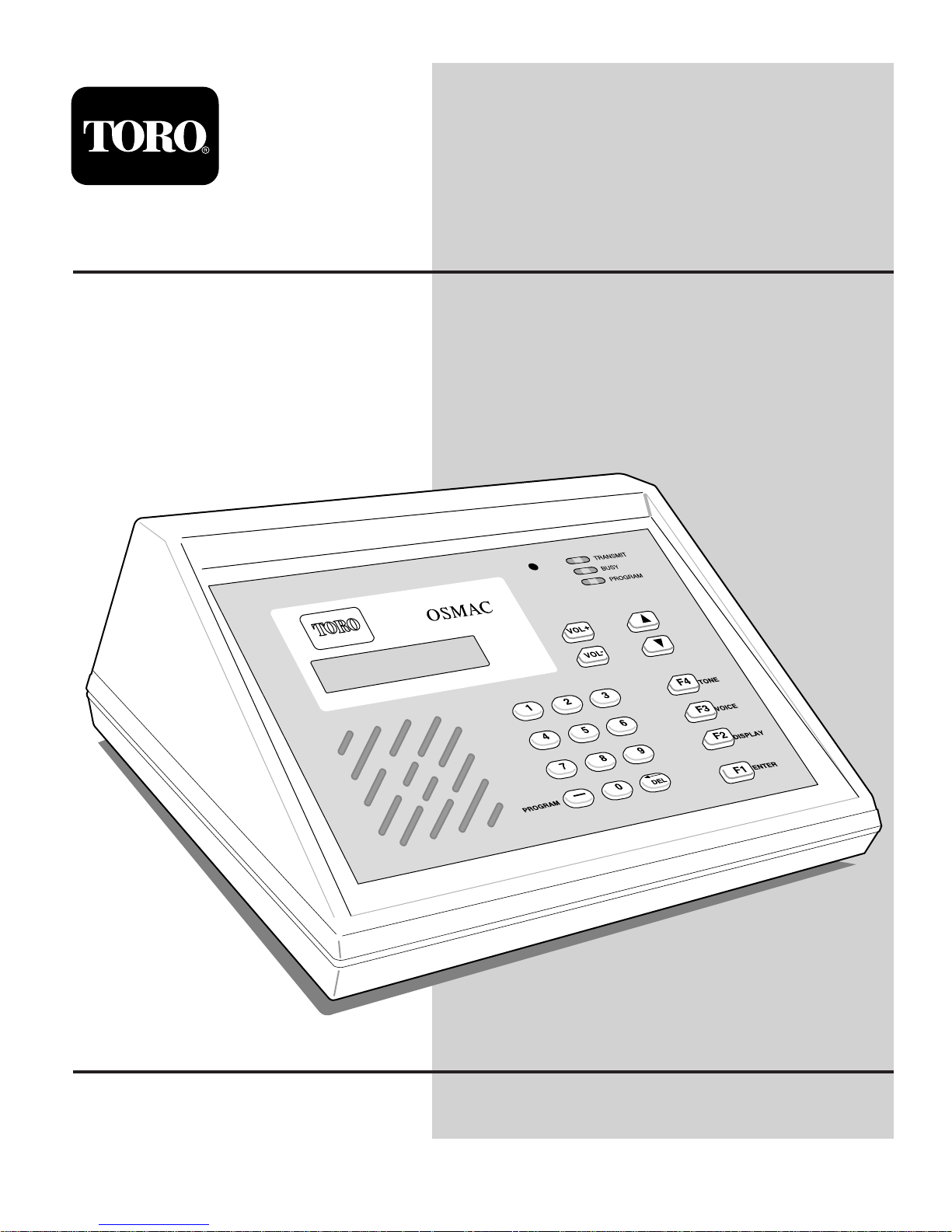
Figure 1
Microphone
Status Indicators
Keypad
Liquid Crystal Display (LCD)
with Back Light.
Speaker
PROGRAMPROGRAM
TRANSMITTRANSMIT
BUSYBUSY
PROGRAMPROGRAM
TONE
TONE
VOICEVOICE
DISPLAYDISPLAY
ENTERENTER
Page 6
4
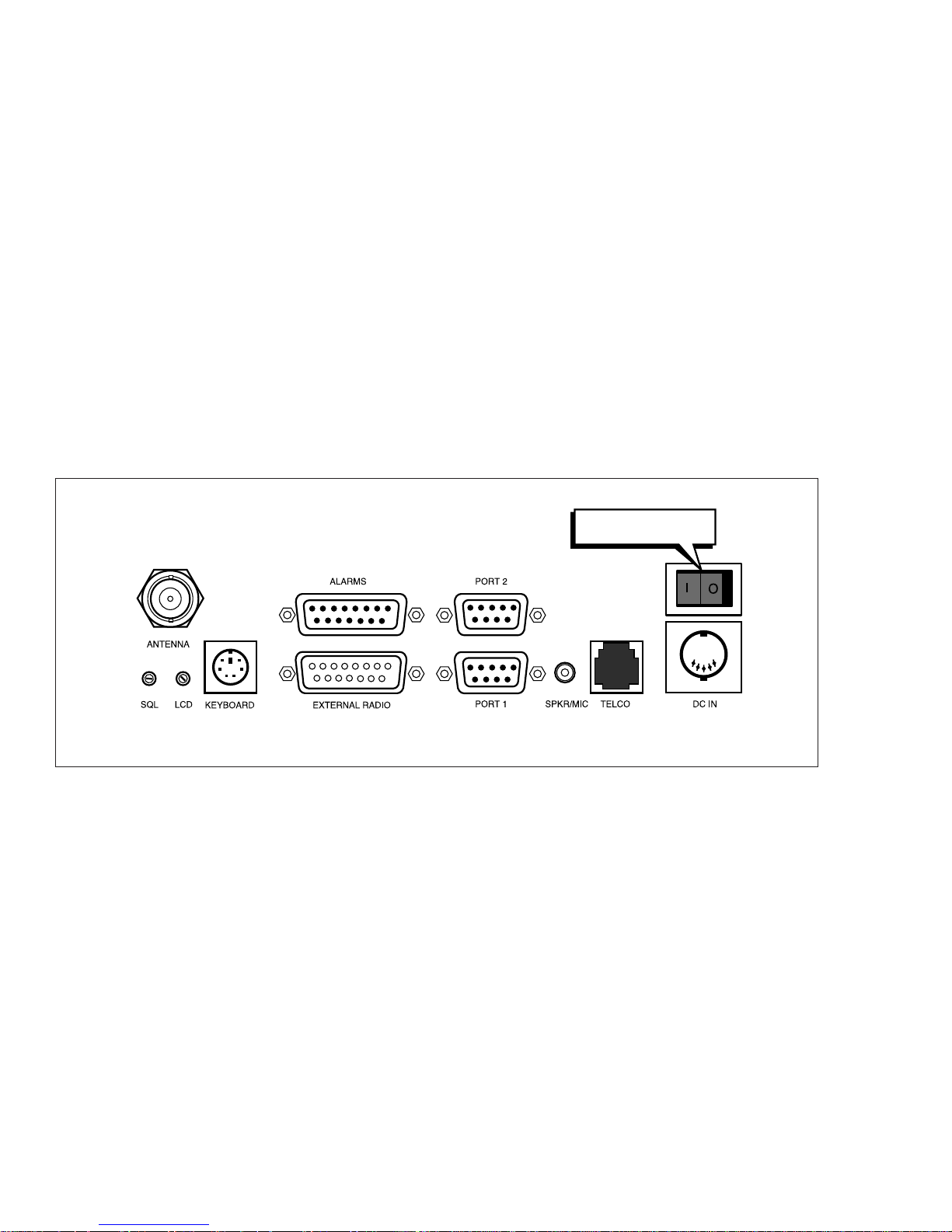
Rear Panel Connections
Telephone Interface
The OSMAC Base Station telephone interface may be utilized for generating command codes or initiating phone patches
with two-way radios. The Base Station has a built-in radio transceiver which enables it to communicate with other twoway radios. The base station can receive over-the-air commands to generate command codes, connect to the telephone
system, dial phone numbers and answer incoming telephone calls.
External Transceiver
The OSMAC Base Station may utilize an internal transceiver, an external transmitter, or an external transceiver. A 15-pin
D-sub connector is provided on the back panel of the Base Station to facilitate interface with an external transmitter or
external transceiver to the Base Station.
Serial I/O Ports
The OSMAC Base Station has two RS-232 Serial I/O ports. These ports can be used to connect the base station to a
central controller such as SitePro or TouchNet.
Auxiliary/Alarm Connector
A 15-pin D-sub female connector is provided on the back of the unit and labeled as ALARMS. This connector can read
digital inputs used for triggering alarms. The digital inputs can be programmed to automatically generate satellite commands.
Note: All digital alarm inputs have an internal 10K pull-up resistor connected. Alarms are activated by pulling the input to
ground. Open circuit or a TTL/CMOS high level is in the inactive state. Do not pull these inputs above 5V.
Figure 2
Rear Panel View
ON / OFF Power Switch
Page 7

5
INSTALLATION
Locating the OSMAC Base Station
The OSMAC Base Station is designed for an indoor office environment. Choose a location where the ambient air temperature is be between -10C and +40C, and relative humidity in the 20 – 80% range. Operation outside of this range may
cause damage to the unit.
The OSMAC Base Station is an interface between SitePro or TouchNet and field satellites. The base station does not
store irrigation programs, however it can be used to send simple commands to field satellites by itself, e.g., turn off and on
satellite stations.
Figure 4 and Figure 5 show the cable connection necessary to interface the base station to either TouchNet
or SitePro.
Power Connection
The OSMAC Base Station requires an external
5.0 V d.c. and 12.0 V d.c., 2A power supply with a DIN
connector.
Antenna Connection
For most installations, it is recommended that the
antenna be located away from the unit and raised high
enough to provide good coverage. Directional type
antennas will provide much better coverage than the
“rubber duck” type antennas. This is particularly helpful
when using an external keyboard since many keyboards malfunction in the presence of a strong radio
frequency fields.
Setup with SitePro
The OSMAC Base Station can be interfaced with
SitePro through port 1 using the SitePro interface cable
kit, part number 102-1201. See Figure 4.
SitePro and the base station should be configured
properly by the Toro distributor or field service representative during installation. If assistance is needed in configuring either the base station or SitePro, please contact your Toro distributor or field service representative.
The OSMAC Base Station will accept manual
commands entered from the its keyboard as well as
from a hand-held radio while running SitePro from the
central controller.
Setup with TouchNet
The OSMAC Base Station can be interfaced with
TouchNet through port 1 using the TouchNet interface
cable kit, part number 102-1200. See Figure 5.
TouchNet and the base station should be configured
properly by the distributor or field service representative
during installation. If assistance is needed in configuring either the base station or TouchNet, please contact
your distributor or field service representative.
The base station will accept manual commands entered
from its keyboard as well as from a hand-held radio
while connected to TouchNet for automated irrigation.
Figure 3
Figure 4
Figure 5
Antenna
Toro P/N 102-1201
Base Station/SitePro
Interface Cable
PORT 1
Power Supply
(Computer)
Rocket Port
25 Pin Female Socket
( TouchNet )
25 Pin Female Socket
Toro P/N 102-1200
Base Station / Touchnet Interface Cable
PORT 1
Page 8

6
BASE STATION OPERATION
Manual Operation Overview
The OSMAC Base Station is used to operate the E-Series OSMAC and adapted OSMAC RDR-Type system. Operation
can be performed using the built-in keypad, a hand-held radio, or a telephone. The database stored in the OSMAC Base
Station is pre-configured for satellite address numbers from 1 through 399. Therefore, no database configuration is necessary for manual operation.
Keypad Operation
An E-Series OSMAC system can be manually operated by the user with the OSMAC Base Station keypad.
While in normal paging mode, the “PAGER NO =” prompt will be shown on the LCD. To issue a command to a satellite,
the user must enter the satellite address number by typing it on the keypad and then pressing the F1 (Enter) key. The
prompt on the LCD will change to “ENTER MESSAGE.” At this point, the user can enter the satellite command to be
issued to the satellite controller. The satellite command will be transmitted by the base station after the user presses the
F1 key or base station time-out.
The following example shows how to command satellite address number 33 to turn on station 17 for 5 minutes:
LCD Displays: "PAGER NO ="
User Enters: 33 F1
LCD Displays: "ENTER MESSAGE"
User Enters: 75180517 F1
The OSMAC Base Station will now transmit the satellite command. A description of all possible satellite commands is located
in Appendix B.
Hand-Held Radio Operation
Satellite commands for the OSMAC Base Station can be initiated remotely by using a hand-held radio with a DTMF keypad. Enter the keypad sequence 9 on the hand-held radio to notify the OSMAC Base Station that a satellite command
is being initiated remotely. The base station will respond with “ENTER PAGER NUMBER.” The satellite address number
to be controlled can now be entered on the hand-held radio keypad. The satellite number must be three digits, and leading zeros must be added to satellite number that are shorter than three digits. For example, to enter satellite number 47,
047 must be entered on the hand-held radio keypad.
After the satellite address number is entered, the OSMAC Base Station will respond with “ENTER THE MESSAGE.”
Note: If a satellite address number is not entered within a few seconds, the Base Station will respond with “TIME-OUT
ERROR,” and the user must re-enter the
9 sequence if a manual command is to be sent.
The user may now enter the command to be sent using the DTMF keypad on the hand-held radio. Once the satellite
command has been entered, the base station will respond with “MESSAGE DELIVERED.”
Optionally, the whole command code sequence including
9, the three digit address and the satellite command to be
sent, can be entered all at once without waiting for the voice prompts from the OSMAC Base Station. This allow users
that are familiar with the OSMAC Base Station operation to enter commands more quickly.
The following example demonstrates how to send a satellite command from the hand-held radio to instruct satellite
address number 13 to turn on stations 3, 4, and 5 for one hour and 15 minutes:
User Enters:
9
OSMAC Base Station Response: "ENTER PAGER NUMBER"
User Enters: 013
OSMAC Base Station Response: "ENTER THE MESSAGE"
User Enters: 7517011500030405
OSMAC Base Station Response: "MESSAGE DELIVERED"
The user will now hear the satellite command being transmitted from the OSMAC Base Station.
Any of the satellite commands (listed in Appendix B) which can be entered through the built-in keypad of the OSMAC
Base Station, can also be entered through a hand-held radio. In addition, there are a few special commands that are
available to enhance manual operation through a hand-held radio. These extra satellite commands are also described in
Appendix B.
Page 9

7
Telephone Operation
If the OSMAC Base Station is connected to a phone line, satellite commands can be initiated remotely through a touchtone telephone. In order for satellite commands to be initiated via telephone, the REMOTE PAGING feature of the
OSMAC Base Station must be enabled.
The OSMAC Base Station will answer the telephone line when properly configured. It will immediately respond with
“ENTER PAGER NUMBER.” The user can then enter the satellite address number on the telephone keypad followed
by the # key. The base station will then prompt “ENTER THE MESSAGE” at which the user enters the satellite command
to be sent followed by the # key. The base station will respond with “MESSAGE DELIVERED,” and will then transmit the
satellite command. After sending the satellite command, the OSMAC Base Station will again prompt: “ENTER PAGER
NUMBER.” The user can enter another satellite address number to continue sending satellite commands or hang up the
telephone to quit.
The base station will disconnect the phone line and report "TIME-OUT ERROR" if at any time the user takes more than a
few seconds to make an entry on the telephone keypad. The user must have to call the OSMAC Base Station again if
telephone operation is desired.
The following example demonstrates how to turn on station 2 of satellite address number 25 for 10 minutes using the telephone interface:
User Enters: Telephone number for line connected to OSMAC Base Station.
OSMAC Base Station Response: Answers phone followed by "ENTER PAGER NUMBER."
User Enters: 025#
OSMAC Base Station Response: "ENTER THE MESSAGE"
User Enters: 75181002# (See note below)
OSMAC Base Station Response: "MESSAGE DELIVERED"
The OSMAC Base Station then transmits the command and returns to the “ENTER PAGER NUMBER” prompt.
Note: See Appendix B for a description of all satellite commands that can be initiated via the telephone interface.
Page 10

8
ADVANCED HAND HELD RADIO OPERATION
Placing Telephone Calls at the Two-Way Radio
Two-way radios can place “Autopatch” telephone calls through OSMAC Base Station using the telephone line connected
to the rear of the base station. The base station operates in a simplex mode. In other words, it can only receive or transmit at any given time but not simultaneously. If the Base Station is transmitting, it cannot receive. Conversely, when it is
receiving, it cannot transmit. The Base Station uses a Voice Operated Switch (VOX) circuit on the telephone line. The
VOX circuit switches the Base Station from transmit mode to receive mode when it detects the incoming audio from the
telephone line has stopped.
To place a telephone call:
1. Press the
7 keys on the two-way radio DTMF keypad. This tells the base station that you wish to place a telephone
call.
2. Listen for the dial tone to come back from the base station. If Autopatch operation has been disabled (Autopatch
timer=0) from the Configuration Menu, then an error message will be heard.
3. Begin dialing the telephone number you wish to call after the dial tone ends. After entering the telephone number, you
have to press the
key to place the call. Alternatively, the phone number will be dialed if no keys are pressed after a
few seconds. The DTMF tones being sent to the phone line will be heard to confirm dialing.
4. Once the called party answers, the phone VOX circuit takes over. When the called party speaks, OSMAC Base
Station transmits his or her voice.
5. A periodic ticking sound will be heard by the mobile user as the base station briefly switches from transmit mode to
receive mode to determine whether the mobile user wishes to interrupt the conversation and has begun transmitting.
6. If neither party is talking, a single beep will be heard periodically to remind the mobile user that the phone patch is still
in operation.
7. A time-out timer exists in order to shut down the phone patch automatically in the event that the mobile user goes out
of range or has a battery outage. Warning beeps or a voice message will be sent 30 seconds before the time-out
timer expires and the phone call is terminated. The mobile user may press the
key in order to reset the time-out
timer and continue the phone call.
8. End the conversation from the two-way radio by pressing the # key. A high and low beep sequence or a voice message should be heard to confirm the disconnection.
Autodial Memory
The OSMAC Base Station provides an Autodial Memory feature enabling storage of up to ten telephone numbers which
can be automatically dialed. (Refer to Autodial Memory Programming information on page 13 to enter phone numbers.)
To make an Autodial call from a two-way radio:
1. Press the
6 keys on the two-way radio DTMF keypad, followed by the Autodial Memory number you wish to place
the call to. Memory number 0 will be used if no number is sent after the 6 command.
2. Once the called party answers, the phone VOX circuit takes over. When the called party speaks, OSMAC Base
Station transmits his or her voice.
3. A periodic ticking sound will be heard by the mobile user as the base station briefly switches from transmit mode to
receive mode to determine whether the mobile user wishes to interrupt the conversation and has begun transmitting.
4. If neither party is talking, a single beep will be heard periodically to remind the mobile user that the phone patch is still
in operation.
5. A time-out timer exists in order to shut down the phone patch automatically in the event that the mobile user goes out
of range or has a battery outage. Warning beeps or a voice message will be sent 30 seconds before the time-out
timer expires and the phone call is terminated. The mobile user may press the
key in order to reset the time-out
timer and continue the phone call.
6. End the conversation from the two-way radio by pressing the # key. A high and low beep sequence or a voice message should be heard to confirm the disconnection.
Page 11

9
Receiving Phone Calls at the Two-Way Radio
The OSMAC Base Station can also be used to route telephone calls from the telephone line to a two-way radio.
To initiate a phone call from the telephone interface:
1. Dial the phone number of the telephone line connected to the OSMAC Base Station.
2. The telephone user must press the
5 keys to request a phone call if REMOTE PAGING is enabled.
3. If Call Forwarding is enabled and the telephone line rings, the base station will transmit a simulated ring signal over
the air. To answer the call, a mobile user must press the
key to take the telephone line off-hook.
4. Once the called party answers, the phone VOX circuit takes over. When the phone user speaks, the Base Station
transmits his or her voice.
5. A periodic ticking sound will be heard by the mobile user as the base station briefly switches from transmit mode to
receive mode to determine whether the mobile user wishes to interrupt the conversation and has begun transmitting.
6. If neither party is talking, a single beep will be heard periodically to remind the mobile user that the phone patch is still
in operation.
7. A time-out timer exists in order to shut down the phone patch automatically in the event that the mobile user goes out
of range or has a battery outage. The length of the timer is set in the Configuration Menu. Warning beeps or a voice
message will be sent a few seconds before the time-out timer expires and the phone call is terminated. The mobile
user must press the
key to reset the time-out timer and continue the phone call.
8. End the conversation from the two-way radio by pressing the # key. A high, then low beep sequence or a voice message should be heard to confirm the disconnect.
Note: If uncertain about the settings of Remote Paging and Call Forwarding modes, contact your local Toro distributor or
field service representative.
Page 12

10
PROGRAM MODE
The Program Mode is used to program satellite address numbers, add satellite address numbers, delete satellite address
numbers, assign satellite address numbers to groups, configure the alarm commands and set up various features of the
OSMAC Base Station.
To enter the programming mode, press the – (dash) key on the keypad. The OSMAC Base Station will prompt you to
enter the password. After entering the Program Mode password 7531, press the F1 key.
You can select one of the following menu items:
1 = ASSIGN PAGER Assigns satellite address number
2 = ASSIGN GROUP Assigns satellites address numbers to groups
3 = TEST PAGE Sends periodic test commands
4 = ALARM PAGES Configures alarm triggered commands
5 = AUTODIAL MEMORY Configures Autodial phone numbers
– = RETURN TO PAGE Return back to the page mode
When you enter the Program Mode, you will see the first selections. Use the
arrow keys to scroll through the avail-
able options. To exit the Program Mode, press the – (dash) key. Any changes you make will automatically be saved.
Note: When the OSMAC Base Station is in the Program Mode and no keyboard entry is made within two minutes, the base
station will revert back to the Page Mode, with the exception of test command. Test command will repeatedly send test
commands to satellite address number 0 for an unlimited period of time until terminated by pressing the – (Program) key.
Assigning Satellite Number
The E-Series Satellite Decoder Board has an ID code also known as the CAP code. It is a long number that is difficult to
remember and cumbersome to use. To make operation of the OSMAC system easier, the OSMAC Base Station stores
the satellite ID codes in its internal database and allows the user to assigns each station an easier to remember 3-digit
number called the satellite address number.
The ID code for an OSMAC Satellite is 279XXX, where XXX is the 3-digit satellite address number set by the DIP Switch
on the OSMAC Satellite Decoder Board. For example, if the switch on an OSMAC Satellite Decoder Board is set to 25,
then its ID code is 279025.
The database in the OSMAC Base Station is pre-configured such that the satellite address numbers 0–399 correspond to
ID codes 279000–279399. This should be sufficient for normal use in an OSMAC system. However, if the user wishes to
change the ID code assigned to a satellite address number, this can be done through the ASSIGN PAGER function.
1. Begin by entering the Programming Mode as described above and press the 1 key for ASSIGN PAGER. The OSMAC
Base Station will respond with:
PAGER NO =
DASH (–) TO EXIT
2. Enter the satellite address number of the satellite you wish to edit. For example, to edit satellite address number 15,
press 1 5 and the F1 key to enter. Once a satellite address number is entered, the base station will respond with a
prompt asking for the ID code for this satellite. If the satellite address number is already in the database, it will display
the ID code that is already in the program. If satellite address number is not in the database, the ID code will default
to the satellite address number. To edit the ID code, use the DEL key to backspace over it. Type the new ID code
and press F1 to enter.
Important: The satellite address number must be set in the field satellite for proper communication.
3. After you enter the ID code for the satellite address number, you must tell the Base Station what type of satellite it is
being assigned. The base station will display the default type. Press the arrow keys to cycle through the list of possible satellite types. The possible types are: POCSAG 512, POCSAG 1200, and POCSAG 2400. Select POCSAG 512
for an OSMAC Satellite. Once the correct format type is displayed, press the F1 key to enter.
4. After entering the satellite type, you must now enter the function type of the satellite. The function type is either TONE
(the satellite just beeps), NUMERIC (beeps and displays numbers) or ALPHA (beeps and displays numbers and
letters). OSMAC Satellites are NUMERIC type. Press the orarrow keys to cycle through the list of functions.
Press the F1 key when the correct function type is displayed.
Page 13

11
5. Once the function has been entered, you are prompted to activate the satellite. Press the F1 key to activate it, or
press the arrow key to switch between Y and N on the display. Press the F1 key when the correct response has been
chosen.
6. The OSMAC Base Station will ask whether the satellite address number changes should be saved. Press the F1 key
to select Y if you wish to save the changes. If not, press an
or arrow key to display N, then press the F1 key.
7. The OSMAC Base Station restarts back at the “PAGER NO =” prompt. It will automatically increment to the next satellite address number. Press the – (dash) key to exit the Program Mode when all of the satellites have been entered
into the database. Your entries into the satellite database will then be saved in the internal FLASH memory.
Assigning a Group
The Group-Command feature is used to send the same command to a number of different satellites. Groups can have
assigned satellite address numbers similar to individual satellites. Once you define a group and its members, you can
send command codes to that group just like a single satellite. When you assign a satellite address number to a group, it
is important that the number is not the same as any of the individual satellite address numbers.
There is a limit to the number of satellites that can be assigned to any one group. Individual groups may contain a maximum of 75 individual satellite address numbers. The number of groups that can be assigned is also limited to 16 different
groups.
Note: OSMAC satellites are always considered to be members of group 256.
1. To do the group assignments, select 2 for ASSIGN GROUP from the program mode menu. The display will then
show:
GROUP NUMBER =
SELECT GROUP
2. Enter the number of the group you wish to work on and then press the F1 key. Valid group numbers are 1–16. The
display will then show:
GROUP X PAGER NN (See Note below)
ASSIGN PAGER NUMBER
Note: The X is the group number you wish to work on and NN is the satellite address number assigned to this group.
Important: When you wish to send a command to this group, you will enter the satellite number NN, not the group number.
3. Use the DEL key to backspace over NN if you wish to change the satellite address number the group is assigned to.
If the satellite address number NN is already assigned to an active satellite, the OSMAC Base Station will not allow
you to assign that number to the group and the satellite group will be erased. If you wish to use NN for the group
number rather than for the individual satellite, you must first deactivate that particular satellite number. Once the satellite address number for this group is set, press the F1 key. The following prompt will appear.
GROUP X = NUMERIC
SELECT GROUP FUNC
4. Using the arrow keys, select the function (numeric) for this Satellite group. Members of the group may be of any type,
but this selection will determine the prompt to the user when a command to this group is initiated. Press the F1 key
after selection is made. The display will change to:
GROUP X MEMBER NN
ENTER MEMBER NUMBER
5. The X will be the group number you are currently working on and NN will be a number corresponding to the satellite
address number you wish to edit. The first group member you enter will be satellite 1. The second one you enter will
be satellite 2 and so on. The display always shows the next number for the next new satellite. Use the
arrow
keys if you wish to scroll through the group members or press the DEL key to edit the satellite address number and
enter the correct satellite address number you wish to edit. Press the F1 key when you are ready to edit/add the
selected satellite address number for the group. The display will then show:
MEMBER NN =
ENTER PAGER NUMBER
Page 14

12
6. Enter the satellite address number of the satellite you wish to add to the group. For example, if you wish to add satel-
lite address number 123 to the group, then press 1 2 3 and the F1 key to enter. Use the DEL key to backspace over
any entry if you wish to edit make an edit.
Note:
• To review the satellites in the database of the satellite group, you can use the
arrow keys to scroll through the
members of the group.
• To delete a member, use the DEL key to erase the satellite address number you wish to delete from the satellite group
at the “MEMBER NN =” prompt, and press the F1 key.
7. To finish entering satellite address numbers to this group, press the – (dash) key.
Sending Test Commands
The test command mode may be used to check the range of the system. With this mode, the OSMAC Base Station will
automatically generate a command to satellite address number 0 every ten seconds.
1. Before using this feature, satellite address number 0 must be programmed.
2. To enable this feature, enter the program mode and press 3 for Test Page. The display will show:
PAGING PAGER 0
DASH (–) TO EXIT
3. Press the – (dash) key to return to the programming mode menu.
Alarm Commands
The OSMAC Base Station has 8 alarm inputs. These digital inputs are used to generate pre-programmed commands.
Each input will send its own pre-programmed command to any satellite, or group of satellites. These can be used for
alarms, but they can also be used to simply generate pre-programmed commands.
The alarm inputs are designed for connection to normally-open switches or contacts. When any alarm input is pulled low
to ground, it will generate a pre-programmed command. When any input is pulled high or allowed to “float high”, it will
generate a different pre-programmed command.
Important The alarm inputs are not surge protected. Supplemental surge protection on the field wiring is recommended in
lightning-prone areas. Contact your local Toro field service representative for assistance.
Pin Number Connection
1 Alarm 1
2 Alarm 2
3 Alarm 3
4 Alarm 4
5 Alarm 5
6 Alarm 6
7 Alarm 7
8 Alarm 8
9 No Connection
10 No Connection
11 No Connection
12 No Connection
13 No Connection
14 No Connection
15 Ground
Figure 6
Alarm/Pin Number Position
(Not Used)
Ground
3
1
2
9
8
15
7
6
14
5
4
Page 15

13
To set up the Alarm commands, perform the following steps:
1. Select the Program mode by pressing the – (dash) key on the keypad. The OSMAC Base Station will prompt you to
enter the password. Press 7 5 3 1 and the F1 key.
2. Press 4 to enter the Alarm sub-menu.
3. When the “ALARM NUMBER =” prompt is shown, enter the number of the alarm you wish to configure. Press the F1
key.
4. When the alarm is triggered, the OSMAC Base Station will display “ALARM X PAGER” on the top line, and the satellite address number that will be triggered. Erasing the satellite address number disables the alarm. Enter the satellite
address number you wish to command when the selected alarm input is triggered. Press the F1 key when done.
5. The Base Station will display “ALARM LOW MSG:” on the top line of the LCD. On the second line, you may enter or
edit the command code to be sent when the alarm input goes low. Press the F1 key when the message has been
entered.
6. The Base Station will display “ALARM HI MSG:” on the top line of the LCD. On the second line, you may enter or edit
the command code to be sent when the alarm input goes high. Press the F1 key when the message has been
entered.
When entering the alarm messages, the unit keys operate as follows:
• Numeric keys are used to enter numbers
• F4 or arrow key selects the next letter of the alphabet
• F3 or arrow key selects the previous letter of the alphabet
• – key enters a “dash” character
• F2 key enters a space character or moves to the next character position to the right
• DEL key deletes a character and moves to the next character position to the left
• F1 key accepts the entry and exits back to the previous menu
• Alphanumeric characters may alternatively be entered directly from an external keyboard
7. Press the F1 key to return to the Programming mode menu.
Autodial Memory
The OSMAC Base Station provides an Autodial Memory feature enabling storage of up to 10 telephone numbers which
can be automatically dialed. These must be programmed prior to use by two-way radio users.
To program the Autodial phone numbers:
1. Select the Program mode by pressing the – (dash) key on the keypad. The OSMAC Base Station will prompt you to
enter the password. Press 7 5 3 1 and the F1 key.
2 Press 5 to enter the Autodial Memory sub-menu.
3. Either press number key 0–9 or use the
arrow keys to step through the Autodial memory. The first 20 characters
of the Autodial phone number will be displayed.
Note: Each phone number can be up to 30 characters in length.
4. To enter or change the contents of the Autodial Memory, enter the new phone number using the number keys on the
keypad. The following keys have special functions:
Key Character Displayed Function
–
_
(underscore) Insert a pause in the dialing sequence
DEL {none} Delete the previous character
F1 {none} Save the phone number
F2 # DTMF # key
F3
DTMF key
F4 F Flash hook
5. Press the F1 key to save the phone number.
6. Repeat steps 3 through 5 as desired, then press the – (dash) key to exit to the main programming menu.
Page 16

14
APPENDIX A - OSMAC Configuration Commands
Serial Port Setup
Each of the two serial ports may be configured independently. The serial ports are located at the rear of the unit and are
labeled PORT 1 and PORT 2. Contact your local Toro distributor or field service representative for SitePro or TouchNet
setup.
TAP (also called IXO)
The Telocator Access Protocol is an industry standard protocol for communications between OSMAC Base Station and
E-Series satellite controllers. Individual satellites can be sent individual commands.
COMP1
This protocol is a simple way to send commands to one satellite. It is designed to allow a person with a simple computer
terminal to type a command codes into the OSMAC Base Station. The base station must be pre-configured with the ID
code of the satellite you wish to send commands to. All data sent into the serial port of the Base Station will be sent to
that particular satellite controller.
COMP2
COMP2 is similar to COMP1, except each command requires two lines of text to be entered. The first line is the satellite
address number to transmit the command to, and the second line is the numeric command code to send to that satellite
controller.
Speaker Enable
If this mode is disabled, then the speaker is muted at all times except in the Diagnostics Mode. This may be used if the
OSMAC Base Station is in a location where sounds from the speaker are not desirable.
Busy Channel Lockout
If this mode is enabled, then the OSMAC Base Station will not transmit if the channel is busy. This may be desirable in
order to avoid interfering with other users on the radio channel. This mode can be disabled when too much activity on the
channel exist and commands cannot be sent out in a timely manner.
Remote Paging
If this mode is enabled, then remote users are permitted to call the OSMAC Base Station via a telephone line to generate
command codes to be transmitted.
Call Forwarding
If this mode is enabled, then remote users are permitted to call the OSMAC Base Station via a telephone line to request a
phone autopatch with two-way radio users.
Autopatch Timer
The Autopatch Timer establishes the length of time the OSMAC Base Station waits before hanging up the autopatch automatically. This is needed in case the two-way radio batteries fail or the radio goes out of range.
Enter the number of minutes autopatch may be operated before the disconnect warning tones are sent. The DEL key may
be used to delete digits. Press the – (dash) key to exit the menu. Setting the Autopatch Timer to a value of 0 will disable
the autopatch operation.
Voice Prompts
This mode selects whether beeps or voice prompts are used to confirm radio and phone operations with the OSMAC
Base Station.
Warmup Signal
If this mode is enabled, then a special “warmup” signal is transmitted for a brief period of time at the beginning of each
command. This is required for more reliable operation by some satellites.
Transceiver Setup
The OSMAC Base Station either contains a two-way transceiver or works with an external transceiver. In either case, it
has been programmed with the correct Transmitter Type, Carrier Detect inversion, Transmit Data inversion and TX
Bandwidth modes. The user should not change these settings or improper operation will result.
Transmit and Receive Frequencies
Enter the desired transmit or receive operating frequency using the number keys. The decimal point will automatically be
entered. Use the DEL key to delete any incorrect entries. Press the F1 or – (dash) key to accept the new frequency.
Page 17

15
Transmit and Receive Signaling
Carrier Squelch operation may be desirable if there are no other users on the channel and there are no interference. In
this mode, the two-way radio users will be able to hear the command signals transmitted by the OSMAC Base Station. To
enable this mode, press 1 to select CARRIER ONLY. Press the – (dash) key to exit the menu.
CTCSS operation should be used if there are other users sharing the channel, if there is excessive interference, or if the
two-way radio users do not want to hear the paging signals. In this mode, a low frequency tone is transmitted along with
the desired audio. The receiver will only be enabled if this tone is present at the correct frequency.
To enable this mode, press 2 to select CTCSS. Use the arrow keys to select the desired tone frequency. Press
the – (dash) or F1 key to accept the frequency and exit the entry mode.
CW Identification Call Sign
In many cases, the rules and regulations under which the OSMAC Base Station is licensed requires the station's Call Sign
to be transmitted using Morse Code at regular intervals for identification purposes. The base station will send the Call
Sign (with CTCSS turned off) every 10 minutes if the Call Sign has been programmed. This feature is set to disabled
when the unit leaves the factory.
To enable this feature, press 5 from the main configuration menu. At the prompt, enter your station's Call Sign from your
license as follows:
• Numbers are entered directly from the keypad.
• Letters and other special symbols are entered by pressing the andarrow keys, and press the F2 key to accept.
• Press the F2 key to enter a space character _ (underscore) which results in a pause in the Morse Code.
• Press the DEL key to delete errors or to disable CW Identification by totally clearing the display.
• Press the F1 or – (dash) key to accept the Call Sign and exit the menu.
Page 18

16
APPENDIX B - Hand-Held Radio Command Codes
Operational Description
Turns off individual stations: e.g., 7510 01 02 40 turns off stations 1, 2 and 40.
Turns on individual stations; e.g., 7511 01 02 40 turns on stations 1, 2 and 40.
Syringes individual satellite stations for a predetermined number of 30-second intervals (already
defined in the satellite); e.g., 7512 01 02 turns on stations 1 and 2 for 30-second intervals.
Disables individual stations; e.g., 7513 01 03 disables stations 1 and 3. After this command, on
and off commands will be ignored for stations 1 and 3 until the stations are re-enabled.
Enables individual stations; e.g., 7514 01 03 enable stations 1 and 3.
Sequentially syringes a specified station number range; e.g., 7515 10 20 will syringe stations 10
through 20 sequentially.
Sequentially syringes individual stations; e.g., 7516 10 11 will syringe stations 10 and 11. Multiple
syringe groups can also be run. Enter two dashes between stations to designate separate syringe
groups; e.g., 7516 10 11 - - 22 24 26 28 will run two syringes at the same time. First on stations
10 and 11, followed by stations 22, 24, 26 and 28.
Turns on individual stations for a specified number of hours, minutes and seconds;
e.g., 7517 01 30 00 23 24 25 turns stations 23, 24 and 25 for 1 hour, 30 minutes and no second.
Turns on individual stations for a specified number of minutes; e.g., 7518 10 23 24 25 turns on
stations 23, 24 and 25 for 10 minutes.
Turns off a sequential station run operation (initiated by command code 7521).
Turns on a sequential station run operation; e.g., 7521 01 turns on station 1. To step forward
through the stations, press * 1; to step back through the stations, press * 2.
Increment to the next predetermined station in a sequential; e.g., 7522 02 will add 02 to the station
number of the currently running station and energize the new station station number. The sequential run will stop when the new number exceeds 64.
Decrement to the previous predetermined station in a sequential run; e.g., 7523 03 will run the station that is 3 stations before the one currently energized. The sequential run will stop when the station number reaches the new station number minus 1.
Turns on individual stations as switches; i.e., does not simultaneously energize the pump.
Note: Will not turn off the pump if already running. e.g., 7524 25 35 45 turns on stations 25, 35
and 45 without energizing the pump.
Turns on individual stations as switches for a given time in minutes; i.e., does not simultaneously
energize the pump in this command string, the run time is entered first, followed by the station
numbers; e.g., 7525 25 05 42 turns on stations 5 and 45 for 25 minutes without energizing the
pump.
Turns on individual stations as switches for the time given in hours, minutes and seconds. In this
command string, the run time is entered first, followed by the station numbers; e.g., 7526 02 30 45
25 26 27 turns on stations 25, 26 and 27 for 2 hours, 30 minutes and 45 seconds.
Turns off all stations (specified satellite only).
Turns off all stations using the sequential shut-down procedure.
Command Code
7510
7511
7512
7513
7514
7515
7516
7517
7518
7520
7521
7522
7523
7524
7525
7526
7540
7542
Page 19

17
Operational Description
Disables all stations in all satellites (rain shutdown). Note: Satellite address number is not used
with 7543 or 7544 command codes. The station will not respond to any further commands until
enabled.
Enables operation of all stations in all satellites. See note above.
Sequentially syringes all stations for a set length of time; e.g., 7546 turns on all stations for the
predetermined number of 30 second intervals as defined in the syringe time.
Disables pump start.
Enables pump start to be assigned to a station; e.g., 8001 48 assigns pump start to station 48.
Disables operation and turns off all station in the satellite with sequential shutdown
Enables operation of all stations in the satellite
Changes the password; e.g., 8004 7531 6108 will change the factory default password (7531) to
6108.
Sets the syringe time in 30-second intervals; e.g., 8006 01 0100 (without a password) or 8006
pppp 01 0100 (with a password) sets the syringe time to 100 intervals (50 minutes). The number
of intervals must be given as four digits with leading zeros but can be no greater than 0255.
Sets the time-out limit in 30-minute intervals. This must be specified using four digits with leading
zeros and no greater value than 0255; e.g., 8006 02 0060 (without a password) or 8006 pppp 02
0060 (with a password) sets the time-out limit to 30 hours.
Enables/disables the password. Use 8007 03 01 to enable password protection or 8007 03 00 to
cancel password protection.
Password disable command. Cancel the requirement of entering the password for every entered
command.
Password enable command. After activation, all commands will require the password to be
entered.
Configures stations as switches. Stations can be specified individually and in combination with a
range of stations; e.g., 8008 01 12 50 - 60 configures stations 1, 12 and 50 through 60 as switches.
Note: Only a single dash is used when entering a range of stations.
Configures stations for irrigation. Stations can be specified individually and in combination with a
range of stations; e.g., 8009 01 20 45 - 48 configures stations 1, 20 and 45 through 48 for irrigation.
Resets EPROM to factory defaults.
SPECIAL COMMAND CODES
Sends command 752101 to place satellite address number xxx in test mode with station 01 active.
Sends command 752201 to satellite. Increments station number in test mode by one.
Sends command 752203. Shuts off current station being tested and increment last station by three
for new station to test.
Sends command 752301. Shuts off current station being tested and decrement station by one for
new station.
Sends command 752302. Shuts off current station being tested and decrement by two for new station.
Sends command 7520 to the last satellite, removing it out of test mode.
Command Code
7543
7544
7546
8000
8001
8003 00
8003 01
8004
8006 01
8006 02
8006 03
8007 03 00
8007 03 01
8008
8009
8011
9 xxx 752101
1
13 or 103
2
22 or 202
0 7520 or 9 xxx
Page 20

SPECIFICATIONS
Encoder/Terminal (general)
Frequencies.................................................................................................450-470MHz, 403-512MHz*
Command Format.......................................................................................POCSAG (numeric at 512 bps)
Squelch formats..........................................................................................CTCSS or carrier squelch
Serial port protocols....................................................................................TAP, COMP2, COMP1
Satellite database maximum size...............................................................999 individual satellites
Maximum command length.........................................................................250 characters
Maximum pre-programmed alarm command..............................................40 characters
Maximum number of satellite groups.........................................................16 groups
Maximum number of satellites per group...................................................75 satellite numbers
LCD display size.........................................................................................20 characters X 2 lines
Speaker audio (2-way version only)...........................................................1 watt maximum at <5% THD
Power supply...............................................................................................External 12.0 V d.c.& 5.0 V d.c., 2A,
DIN connector.
Weight.........................................................................................................3.5 lbs.
Temperature range......................................................................................-10 – +40C
Relative Humidity range.............................................................................20 – 80%
Processor....................................................................................................80386EX
Non-volatile flash memory size...................................................................2M bytes
External keyboard interface........................................................................Standard PS/2
Telephone interface.....................................................................................RJ-11 female, DTMF signaling
Alarm/Data inputs........................................................................................8
RF Section
RX channel spacing....................................................................................12.5kHz (narrow band) or 25kHz
(wideband) models available
Frequency Stability......................................................................................2.5ppm (12.5kHz BW version)
5ppm (25kHz version)
RX Sensitivity..............................................................................................0.5uV (12dB SINAD)
0.35uV (2.5kHz version)
RX Modulation acceptance........................................................................ ±2.5kHz (12.5kHz version)
±5kHz (25kHz version)
RX Intermodulation.....................................................................................55dB
RX Image and 1/2 if rejection.....................................................................55dB
RX Selectivity..............................................................................................55dB (25kHz version)
55dB (12.5kHz version)
TX power output......................................................................................... 2 or 4 watts (selected via internal jumper)
Modulation limit...........................................................................................±4.5kHz or ±2.25kHz,
(programmable by channel)
FM hum and noise......................................................................................38dB or better
Spurious emissions.....................................................................................-52dBc
Emission Designators.................................................................................16K0F1D, 11K0F1D, 16K0F3E, 11K0F3E
Please note: The above specifications are subject to change without notice.
Electromagnetic Compatibility
Complies with Part 68, Part 22 and Part 90 of the FCC Rules. Ringer Eq No.: 6
FCC Reg #: OMSUSA - 27556 - PA - T
FCC ID #: MNT - PC - UC
Domestic: This equipment generates and uses radio frequency energy and if not installed and used properly, that is, in strict accordance with the manufacturer's instructions,
may cause interference to radio and television reception. It has been type tested and found to comply with the limits for a FCC Class B computing device in accordance with
the specifications in Subpart J of Part 15 of FCC Rules, which are designed to provide reasonable protection against such interference in a residential installation. However,
there is no guarantee that interference will not occur in a particular installation. If this equipment does cause interference to radio or television reception, which can be determined by turning the equipment off and on, the user is encouraged to try to correct the interference by one or more of the following measures:
• Reorient the receiving antenna.
• Relocate the irrigation controller with respect to the receiver.
• Move the irrigation controller away from the receiver.
• Plug the irrigation controller into a different outlet so that the irrigation controller and receiver are on different branch circuits.
If necessary, the user should consult the dealer or an experienced radio/television technician for additional suggestions. The user may find the following booklet prepared by
the Federal Communications Commission helpful:
"How to Identify and Resolve Radio-TV Interference Problems". This booklet is available from the U.S. Government Printing Office, Washington, DC 20402. Stock No. 004-00000345-4.
International: This is a CSPR 22 Class B product
© 2004 The Toro Company, Irrigation Division Form Number 373-0099 Rev. B
 Loading...