

Page 1
FormNo.3393-823RevC
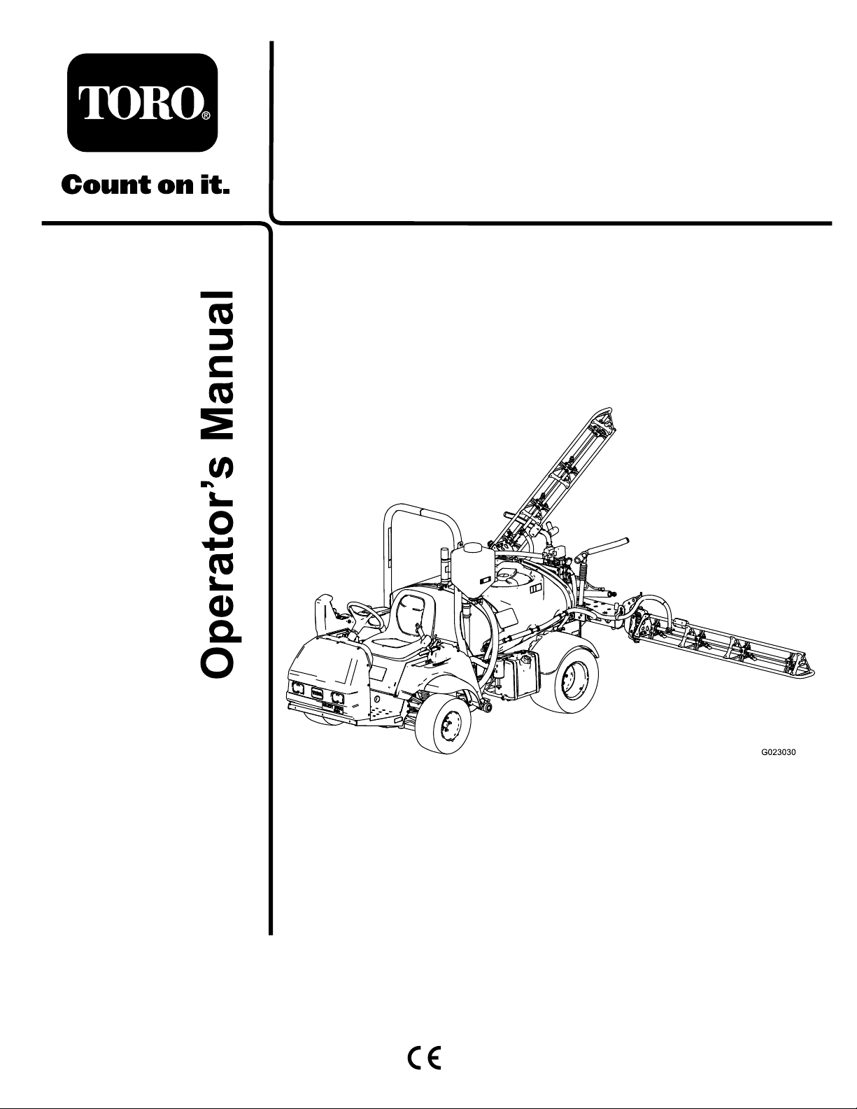
MultiPro
ModelNo.41188—SerialNo.315000001andUp
®
1750TurfSprayer
Registeratwww.T oro.com.
OriginalInstructions(EN)
*3393-823*C
Page 2
TheMultiProturfsprayerisadedicatedturfsprayapplication
vehicleandisintendedtobeusedbyprofessional,hired
operatorsincommercialapplications.Itisprimarilydesigned
forsprayingonwell-maintainedlawnsinparks,golfcourses,
sportselds,andoncommercialgrounds.
ThisproductcomplieswithallrelevantEuropeandirectives;
fordetails,pleaseseetheseparateproductspecicDeclaration
ofConformity(DOC)sheet.
Introduction
Readthismanualcarefullytolearnhowtooperateand
maintainyourproductproperly.Theinformationinthis
manualcanhelpyouandothersavoidinjuryandproduct
damage.AlthoughTorodesignsandproducessafeproducts,
youareresponsibleforoperatingtheproductproperlyand
safely.
WARNING
CALIFORNIA
Proposition65Warning
Thisproductcontainsachemicalorchemicals
knowntotheStateofCaliforniatocausecancer,
birthdefects,orreproductiveharm.
Theengineexhaustfromthisproduct
containschemicalsknowntotheStateof
Californiatocausecancer,birthdefects,
orotherreproductiveharm.
Useofthisproductmaycauseexposureto
chemicalsknowntotheStateofCalifornia
tocausecancer,birthdefects,orother
reproductiveharm.
Important:Thisengineisnotequippedwithaspark
arrestermufer.ItisaviolationofCaliforniaPublic
ResourceCodeSection4442touseoroperatetheengine
onanyforest-covered,brush-covered,orgrass-covered
land.Otherstatesorfederalareasmayhavesimilarlaws.
YoumaycontactTorodirectlyatwww .Toro.comforproduct
safetyandoperationtrainingmaterials,accessoryinformation,
helpndingadealer,ortoregisteryourproduct.
Wheneveryouneedservice,genuineT oroparts,oradditional
information,contactanAuthorizedServiceDealerorToro
CustomerServiceandhavethemodelandserialnumbersof
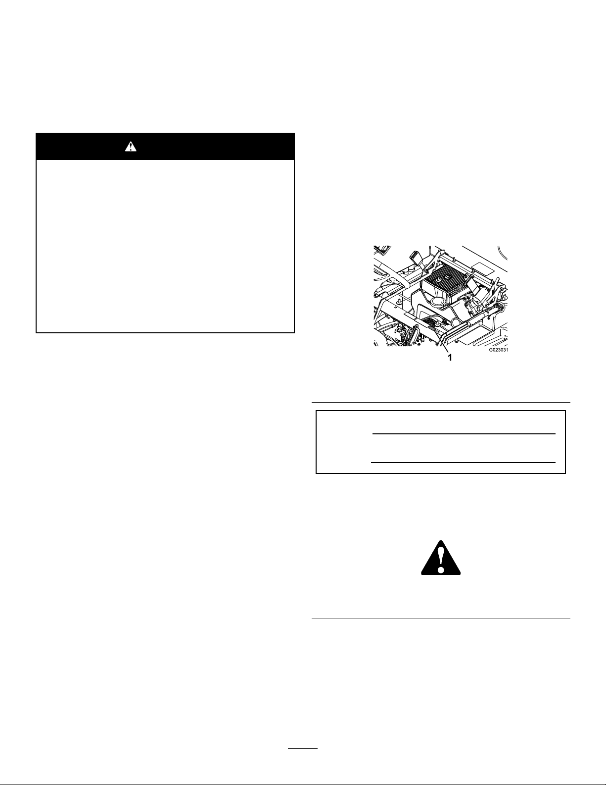
yourproductready.Figure1illustratesthelocationofthe
modelandserialnumbersontheproduct.
Figure1
1.Locationofthemodelandserialnumbers
ThissparkignitionsystemcomplieswithCanadianICES-002.
Theenclosed
informationregardingtheUSEnvironmentalProtection
Agency(EPA)andtheCaliforniaEmissionControl
Regulationofemissionsystems,maintenance,and
warranty.Replacementsmaybeorderedthroughthe
enginemanufacturer.
Engine Owner's Man ual
issuppliedfor
ModelNo.
SerialNo.
Thismanualidentiespotentialhazardsandhassafety
messagesidentiedbythesafetyalertsymbol(Figure2),
whichsignalsahazardthatmaycauseseriousinjuryordeath
ifyoudonotfollowtherecommendedprecautions.
Figure2
1.Safetyalertsymbol.
Thismanualuses2wordstohighlightinformation.
Importantcallsattentiontospecialmechanicalinformation
andNoteemphasizesgeneralinformationworthyofspecial
attention.
©2015—TheToro®Company
8111LyndaleAvenueSouth
Bloomington,MN55420
Contactusatwww.Toro.com.
2
PrintedintheUSA.
AllRightsReserved
Page 3

Contents
Safety...........................................................................4
SafeOperatingPractices...........................................4
ChemicalSafety.......................................................5
WhileOperating......................................................5
Maintenance...........................................................7
SoundPower..........................................................7
SoundPressure.......................................................7
Hand-ArmVibration...............................................7
WholeBodyVibration.............................................7
SafetyandInstructionalDecals.................................8
Setup...........................................................................14
1InstallingtheAnti-siphonFillReceptacle.................14
2CheckingtheBoomHingeSprings.........................14
3LearningMoreaboutYourProduct........................15
ProductOverview.........................................................16
Controls...............................................................18
Specications........................................................21
Attachments/Accessories........................................21
Operation....................................................................22
SafetyFirst............................................................22
PreparingtoDrivetheSprayerfortheFirst
Time.................................................................22
PerformingthePre-StartingChecks..........................23
DrivingtheSprayer.................................................23
BreakinginaNewSprayer.......................................24
AdjustingtheBoomstoLevel..................................24
OperatingtheSprayer.............................................25
FillingtheFreshWaterTank....................................26
FillingtheSprayTank..............................................26
OperatingtheBooms..............................................26
Spraying................................................................26
SprayingTips.........................................................27
CleaningtheSprayer...............................................27
UsingtheInfoCenterLCDDisplay...........................28
CalibratingtheSprayerFlow....................................30
CalibratingtheSprayerSpeed...................................31
CalibratingtheBoom-SectionBypassValves..............32
AgitationBypassValveKnobPosition.......................32
CalibratingtheAgitationBypassValve.......................33
AdjustingtheMasterBoomBypassValve...................33
LocatingthePump.................................................33
TransportingtheSprayer.........................................34
TowingtheSprayer.................................................34
Maintenance.................................................................35
RecommendedMaintenanceSchedule(s)......................35
DailyMaintenanceChecklist....................................36
NotationforAreasofConcern.................................37
PremaintenanceProcedures........................................38
JackingUptheSprayer............................................38
Lubrication...............................................................38
GreasingtheSprayer...............................................38
GreasingtheBoomHinges......................................38
EngineMaintenance..................................................39
CheckingtheAirIntakeScreen.................................39
ServicingtheAirCleaner.........................................39
ServicingtheEngineOil..........................................40
ChangingtheSparkPlugs........................................41
FuelSystemMaintenance...........................................42
ReplacingtheFuelFilter..........................................42
DrainingtheFuelTank...........................................42
ElectricalSystemMaintenance....................................43
LocatingtheFuses..................................................43
ServicingtheBattery...............................................43
DriveSystemMaintenance.........................................45
InspectingtheWheelsandTires...............................45
AdjustingtheFrontWheelToe-in.............................45
BrakeMaintenance....................................................46
CheckingtheBrakeFluid.........................................46
InspectingtheBrakes..............................................46
AdjustingtheParkingBrake.....................................46
HydraulicSystemMaintenance....................................47
CheckingtheTransaxle/HydraulicFluid....................47
ChangingTransaxle/HydraulicFluid.........................47
ReplacingtheHydraulicFilter..................................48
SpraySystemMaintenance..........................................48
InspectingtheHoses..............................................48
ChangingthePressureFilter....................................49
InspectingthePump...............................................49
InspectingtheNylonPivotBushings.........................49
SprayerFlowDiagram.............................................51
Cleaning...................................................................52
CleaningtheFlowmeter..........................................52
CleaningtheSuctionStrainer...................................52
CleaningtheSprayerValves.....................................53
Storage........................................................................62
Troubleshooting...........................................................64
3
Page 4

Safety
•Neverallowuntrainedpeopletooperateorservicethe
equipment.
Improperuseormaintenancebytheoperatororownercan
resultininjury.Toreducethepotentialforinjury,comply
withthesesafetyinstructionsandalwayspayattentionto
thesafetyalertsymbol,whichmeansCaution,Warning,or
Danger—“personalsafetyinstruction.”Failuretocomply
withtheinstructionmayresultinpersonalinjuryordeath.
ThemachinemeetstherequirementsofSAEJ2258.
SafeOperatingPractices
Important:Themachineisdesignedprimarilyasan
off-roadvehicleandisnotintendedforextensiveuseon
publicroads.Whenusingthemachineonpublicroads,
followalltrafcregulationsanduseanyadditional
accessoriesthatmayberequiredbylaw,suchaslights,
turnsignals,slowmovingvehicle(SMV)sign,and
othersasrequired.
TheMulti-Pro1750TurfSprayerwasdesignedandtestedto
offersafeservicewhenoperatedandmaintainedproperly.
Althoughhazardcontrolandaccidentpreventionpartiallyare
dependentuponthedesignandcongurationofthemachine,
thesefactorsarealsodependentupontheawareness,concern,
andpropertrainingofthepersonnelinvolvedintheoperation,
maintenanceandstorageofthemachine.Improperuseor
maintenanceofthemachinecanresultininjuryordeath.
NotalloftheattachmentsthatadapttotheMulti-Pro1750
TurfSprayerarecoveredinthismanual.Seethespecic
Operator’sManualprovidedwitheachattachmentfor
additionalsafetyinstructions.Readthesemanuals.
Toreducethepotentialforinjuryordeath,complywiththe
followingsafetyinstructions:
Note:Localregulationsmayrestricttheageofthe
operator.
•Theowner/usercanpreventandisresponsiblefor
accidentsorinjuriesoccurringtohimselforherself,other
people,ordamagetoproperty.
BeforeOperating
•Operatethemachineonlyafterreadingandunderstanding
thecontentsofthismanual.
•Neverallowchildrentooperatethesprayer.
•Neverallowotheradultstooperatethesprayerwithout
rstreadingandunderstandingtheOperator'sManual.
Onlytrainedandauthorizedpersonsshouldoperatethis
sprayer.Makesurethatalloperatorsarephysicallyand
mentallycapableofoperatingthesprayer.
•Thissprayerisdesignedtocarryonlyyou,theoperator.
Nevercarryanypassengersonthesprayer.
•Neveroperatethesprayerwhenundertheinuence
ofdrugsoralcohol.Evenprescriptiondrugsandcold
medicinescancausedrowsiness.
•Donotdrivethesprayerwhenyouaretired.Besureto
takeoccasionalbreaks.Itisveryimportantthatyoustay
alertatalltimes.
•Becomefamiliarwiththecontrolsandknowhowtostop
theenginequickly.
•Keepallshields,safetydevices,anddecalsinplace.Ifa
shield,safetydevice,ordecalismalfunctioning,illegible,
ordamaged,repairorreplaceitbeforeoperatingthe
machine.
Supervisor'sResponsibilities
•Makesurethatoperatorsarethoroughlytrainedand
familiarwiththeOperator'sManual,EngineManual,andall
labelsonthesprayer.
•Establishyourownspecialproceduresandworkrules
forunusualoperatingconditions(e.g.slopestoosteep
forsprayeroperation).
Training
•ReadtheOperator'sManualandothertrainingmaterial
beforeoperatingthemachine.
Note:Iftheoperator(s)ormechanic(s)cannotreadthe
manuallanguage,itistheowner'sresponsibilitytoexplain
thismaterialtothem.
•Becomefamiliarwiththesafeoperationoftheequipment,
operatorcontrols,andsafetysigns.
•Alloperatorsandmechanicsshouldbetrained.The
ownerisresponsiblefortrainingtheusers.
•Wearappropriateclothing;includingahardhat,safety
glasses,longpants,safetyshoes,rubberboots,gloves,and
hearingprotection.Donotwearloosettingclothingor
jewelrywhichcouldgetcaughtinmovingpartsandcause
personalinjury.
Note:Wearingsafetyglasses,safetyshoes,longpants,
andahelmetisadvisableandrequiredbysomelocal
safetyandinsuranceregulations.
CAUTION
Thismachineproducessoundlevelsinexcess
of85dBAattheoperator’searandcancause
hearinglossthroughextendedperiodsof
exposure.
Wearhearingprotectionwhenoperatingthis
machine.
•Avoiddrivingwhenitisdark,especiallyinunfamiliar
areas.Ifyoumustdrivewhenitisdark,besuretodrive
4
Page 5

cautiously,usetheheadlights,andevenconsideradding
additionallights.
•Beextremelycarefulwhenoperatingaroundpeople.
Alwaysbeawareofwherebystandersmightbeandkeep
themawayfromtheworkarea.
•Beforeoperatingthesprayer,alwayscheckthedesignated
areasofthesprayerthatarestatedinthePre-Starting
ChecksintheOperationsection.Ifthemachinedoes
notfunctioncorrectlyorisdamagedinanyway ,donot
usethesprayer.Makesurethattheproblemiscorrected
beforethesprayerorattachmentisoperated.
•Makesuretheoperator’sareaiscleanandfreefrom
chemicalresidueanddebrisbuildup.
•Ensurethatalluidlineconnectorsaretightandallhoses
areingoodconditionbeforeapplyingpressuretothe
system.
•Sincefuelishighlyammable,handleitcarefully.
–Useanapprovedfuelcontainer.
–Donotremovethecapfromthefueltankwhenthe
engineishotorrunning.Allowtheenginetocool
beforefuelingthemachine.
–Donotsmokewhilehandlinggasoline.
–Fillthefueltankofthemachineoutdoors.
–Fillthefueltankofthemachinetoabout25mm(1
inch)belowthetopofthetank(thebottomofthe
llerneck).Donotoverllthefueltank.
–Wipeupanyspilledfuel.
ChemicalSafety
WARNING
•Chemicalsubstancesusedinthesprayersystem
maybehazardousandtoxictoyou,bystanders,
animals,plants,soilsorotherproperty.
•Carefullyreadandfollowthechemicalwarning
labelsandMaterialSafetyDataSheets(MSDS)
forallchemicalsusedandprotectyourself
accordingtothechemicalmanufacturer's
recommendations.Ensurethataslittleskin
aspossibleisexposedwhileusingchemicals.
UseappropriatePersonalProtectiveEquipment
(PPE)toguardagainstpersonalcontactwith
chemicals,suchas:
–safetyglasses,goggles,and/orfaceshield
–respiratororltermask
–chemicalresistantgloves
–rubberbootsorothersubstantialfootwear
–hearingprotection
–cleanchangeofclothes,soap,anddisposable
towels,tobekepton-hand,intheeventof
achemicalspill.
Important:Keepinmindthattheremaybemorethan
onechemicalused,andinformationoneachchemical
shouldbeassessed.
Refusetooperateorworkonthesprayerifthis
informationisnotavailable!
Beforeworkingonasprayersystem,makesurethatthe
systemhasbeentriplerinsedandneutralizedaccording
totherecommendationsofthechemicalmanufacturer(s)
andallofthevalveshavebeencycled3times.
Verifythereisanadequatesupplyofcleanwaterand
soapnearby ,andimmediatelywashoffanychemicals
thatcontactyou.
•Obtainpropertrainingbeforeusingorhandling
chemicals.
•Usethecorrectchemicalforthejob.
•Followthechemicalmanufacturer'sinstructionsfor
thesafeapplicationofthechemical.Donotexceed
recommendedsystemapplicationpressure.
•Donotll,calibrate,orcleantheunitwhenpeople,
especiallychildren,orpetsareinthearea.
•Handlechemicalsinawellventilatedarea.
•Havecleanwateravailableespeciallywhenllingthe
spraytank.
•Donoteat,drink,orsmokewhileworkingwithchemicals.
•Donotcleanspraynozzlesbyblowingthroughthemor
placinginmouth.
•Alwayswashyourhandsandotherexposedareasassoon
aspossibleafteryounishworkingwithchemicals.
•Keepchemicalsintheiroriginalpackagesandstoredin
asafelocation.
•Properlydisposeofunusedchemicalsandchemical
containersasinstructedbythechemicalmanufacturer
andyourlocalcodes.
•Chemicalsandfumesaredangerous;neverenterthetank
orplaceyourheadoverorintheopeningofatank.
•Followalllocal,state,andfederalregulationsfor
spreadingorsprayingchemicals.
WhileOperating
WARNING
Engineexhaustcontainscarbonmonoxide,which
isanodorless,deadlypoisonthatcankillyou.
Donotrunengineindoorsorinanenclosedarea.
•Theoperatorshouldremainseatedwheneverthesprayer
isinmotion.Theoperatorshouldkeepbothhandson
thesteeringwheelwheneverpossible.Keepyourarms
andlegswithinthesprayerbodyatalltimes.
•Alwayswatchoutforandavoidlowoverhangssuchas
treelimbs,doorjambs,andoverheadwalkways.Make
surethereisenoughroomoverheadtoeasilyclearthe
sprayerandyourhead.
5
Page 6

•Failuretooperatethesprayersafelymayresultinan
accident,tipoverofthesprayer,andseriousinjuryor
death.Drivecarefully .Topreventtippingorlossof
control:
–Useextremecaution,reducespeed,andmaintain
asafedistancearoundsandtraps,ditches,creeks,
ramps,unfamiliarareas,oranyareasthathaveabrupt
changesingroundconditionsorelevation.
–Watchforholesorotherhiddenhazards.
Braking
•Slowdownbeforeyouapproachanobstacle.Thisgives
youextratimetostoporturnaway.Hittinganobstacle
candamagethesprayeranditscontents.Moreimportant,
itcaninjureyou.
•GrossVehicleWeight(GVW)hasamajorimpactonyour
abilitytostopand/orturn.Heavyloadsandattachments
makeasprayerhardertostoporturn.Theheavierthe
load,thelongerittakestostop.
–Useextracautionwhenoperatingthesprayeronwet
surfaces,inadverseweatherconditions,athigher
speeds,orwithafullload.Stoppingtimeanddistance
willincreasewithafullload.
–Avoidsuddenstopsandstarts.Donotgofrom
reversetoforwardorforwardtoreversewithoutrst
comingtoacompletestop.
–Slowdownbeforeturning.Donotattemptsharp
turnsorabruptmaneuversorotherunsafedriving
actionsthatmaycausealossofsprayercontrol.
–Beforebackingup,looktotherearandensurethat
nooneisbehindyou.Backupslowly.
–Watchoutfortrafcwhenyouarenearorcrossing
roads.Alwaysyieldtherightofwaytopedestrians
andothervehicles.Thissprayerisnotdesignedfor
useonstreetsorhighways.Alwayssignalyourturns
orstopearlyenoughsothatotherpeopleknowwhat
youplantodo.Obeyalltrafcrulesandregulations.
–Theelectricalandexhaustsystemsofthesprayercan
producesparkscapableofignitingexplosivematerials.
Neveroperatethesprayerinornearanareawhere
thereisdustorfumesintheairwhichareexplosive.
–Ifyouareeverunsureaboutsafeoperation,stop
workandaskyoursupervisor.
•Donottouchtheengineormuferwhiletheengineis
runningorsoonafterithasstopped.Theseareasmaybe
hotenoughtocauseburns.
•Ifthemachineevervibratesabnormally,stopimmediately ,
waitforallmotiontostop,andinspectthesprayerfor
damage.Repairalldamagebeforeresumingoperation.
•Beforegettingoffoftheseat:
1.Stopthemovementofthemachine.
2.PlacetherangeselectorinNeutralandsetthe
parkingbrake.
3.TurntheignitionkeytoOff.
4.Removetheignitionkey .
•Turfandpavementaremuchmoreslipperywhenthey
arewet.Itcantake2to4timesaslongtostoponwet
surfacesasondrysurfaces.Ifyoudrivethroughstanding
waterdeepenoughtogetthebrakeswet,theywillnot
workwelluntiltheyaredry.Afterdrivingthroughwater,
youshouldtestthebrakestomakesuretheywork
properly.Iftheydonot,driveslowlywhileputtinglight
pressureonthebrakepedal.Thiswilldrythebrakesout.
OperatingonHillsandRoughTerrain
Operatingthesprayeronahillmaycausetippingorrolling
ofthesprayer,ortheenginemaystallandyoucouldlose
headwayonthehill.Thiscouldresultinpersonalinjury.
•Donotacceleratequicklyorslamonthebrakeswhen
backingdownahill,especiallywithaload.
•Neverdriveacrossasteephill;alwaysdrivestraightupor
downorgoaroundthehill.
•Iftheenginestallsoryoubegintoloseheadwaywhile
climbingahill,graduallyapplythebrakesandslowlyback
straightdownthehill.
•Turningwhiletravelingupordownhillscanbedangerous.
Ifyouhavetoturnwhileonahill,doitslowlyand
cautiously.Nevermakesharporfastturns.
•Heavyloadsaffectstability.Reducetheweightoftheload
andyourspeedwhenoperatingonhills.
•Avoidstoppingonhills,especiallywithaload.Stopping
whilegoingdownahillwilltakelongerthanstopping
onlevelground.Ifthesprayermustbestopped,avoid
suddenspeedchanges,whichmayinitiatetippingor
rollingofthesprayer.Donotslamonthebrakes
whenrollingbackward,asthismaycausethesprayerto
overturn.
•Usetheseatbeltwhenoperatingthemachineandbe
certainthatitcanbereleasedquicklyintheeventofan
emergency.
•Donotremoveoraltertherolloverprotectionsystem
(ROPS).
Important:Donotparkthemachineonan
incline.
•Lightningcancausesevereinjuryordeath.Iflightning
isseenorthunderisheardinthearea,donotoperate
themachine;seekshelter.
•Reducespeedandloadwhenoperatingonroughterrain,
unevenground,andnearcurbs,holes,andothersudden
changesinterrain.Loadsmayshift,causingthesprayer
tobecomeunstable.
6
Page 7

WARNING
Suddenchangesinterrainmaycauseabrupt
steeringwheelmovement,possiblyresultingin
handandarminjuries.
•Reduceyourspeedwhenoperatingonroughterrainand
nearcurbs.
•Gripthesteeringwheellooselyaroundtheperimeter.
Keepyourhandsclearofthesteeringwheelspokes.
Loading
Theweightofthecargocanchangethesprayercenterof
gravityandsprayerhandling.Toavoidlossofcontroland
personalinjury,followtheseguidelines:
•Keepyourbodyandhandsawayfrompinholeleaksor
nozzlesthatejecthighpressureuid.Usecardboardor
papertondleaks.Fluidescapingunderpressurecan
penetrateskinandcauseinjuryrequiringsurgerywithin
afewhoursbyaqualiedsurgeon;otherwise,gangrene
mayresult.
•Ifmajorrepairsareeverneededorassistanceisrequired,
contactanAuthorizedToroDistributor.
•Tobesureofoptimumperformanceandsafety,
alwayspurchasegenuineTororeplacementpartsand
accessories.Replacementpartsandaccessoriesmadeby
othermanufacturerscouldbedangerous.Alteringthis
sprayerinanymannerthatmayaffectsprayeroperation,
performance,durability ,oritsuse,mayresultininjuryor
death.Suchusecouldvoidtheproductwarranty.
•Reducetheweightoftheloadwhenoperatingonhills
androughterraintoavoidtippingoroverturningofthe
sprayer.
•Liquidloadscanshift.Thisshiftinghappensmostoften
whileturning,goingupordownhills,suddenlychanging
speeds,orwhiledrivingoverroughsurfaces.Shifting
loadscancausethesprayertotipover.
•Whenoperatingwithaheavyload,reduceyourspeedand
allowforsufcientbrakingdistance.Donotsuddenly
applythebrakes.Useextracautiononslopes.
•Beawarethatheavyloadsincreaseyourstoppingdistance
andreduceyourabilitytoturnquicklywithouttipping
over.
Maintenance
•Onlypermitqualiedandauthorizedpersonnelto
maintain,repair,adjust,orinspectthesprayer.
•Beforeservicingormakingadjustmentstothemachine,
stoptheengine,settheparkingbrake,andremovethekey
fromtheignitiontopreventsomeonefromaccidentally
startingtheengine.
•Tomakesurethattheentiremachineisingoodcondition,
keepallnuts,bolts,andscrewsproperlytightened.
SoundPower
Thisunithasaguaranteedsoundpowerlevelofof98dBA,
whichincludesanUncertaintyValue(K)of1dBA.
Soundpowerlevelwasdeterminedaccordingtothe
proceduresoutlinedinISO11094.
SoundPressure
Thisunithasasoundpressurelevelattheoperator’searof86
dBA,whichincludesanUncertaintyValue(K)of1dBA.
Soundpressurelevelwasdeterminedaccordingtothe
proceduresoutlinedinENISO11201.
Hand-ArmVibration
Measuredvibrationlevelforrighthand=3.00m/s
Measuredvibrationlevelforlefthand=3.20m/s
UncertaintyValue(K)=1.6m/s
Measuredvaluesweredeterminedaccordingtotheprocedures
outlinedinENISO20643.
2
2
2
•Toreducethepotentialforre,keeptheengineareafree
ofexcessivegrease,grass,leaves,andaccumulationofdirt.
•Neveruseanopenametocheckthelevelorleakageof
fuelorbatteryelectrolyte.
•Iftheenginemustberunningtoperformamaintenance
adjustment,keepyourhands,feet,clothing,andanyparts
ofyourbodyawayfromtheengineandanymovingparts.
Keepeveryoneaway.
•Donotuseopenpansoffuelorammablecleaning
uidswhencleaningparts.
•Donotadjustthegroundspeedgovernor.Toensure
safetyandaccuracy ,haveanAuthorizedToroDistributor
checkthegroundspeed.
WholeBodyVibration
Measuredvibrationlevel=0.58m/s
UncertaintyValue(K)=0.29m/s
Measuredvaluesweredeterminedaccordingtotheprocedures
outlinedinEN1032.
7
2
2
Page 8
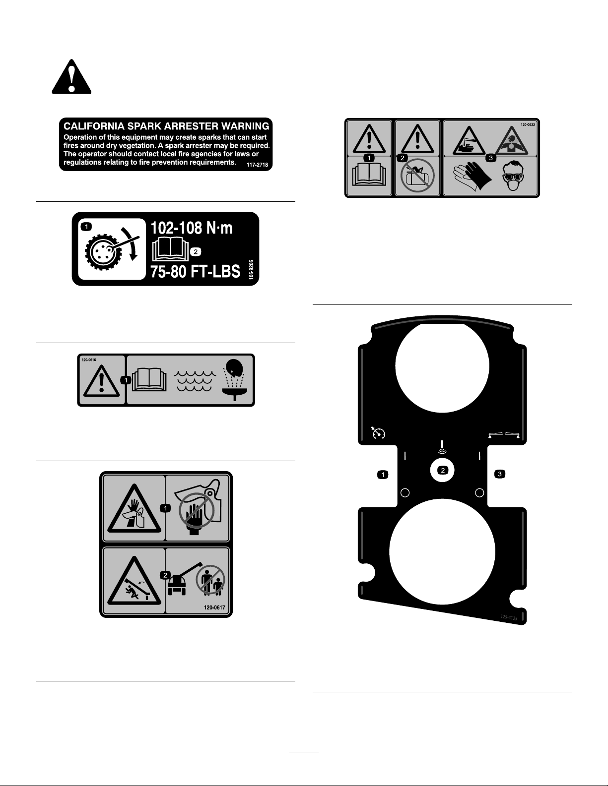
SafetyandInstructionalDecals
Safetydecalsandinstructionsareeasilyvisibletotheoperatorandarelocatednearanyareaofpotential
danger.Replaceanydecalthatisdamagedorlost.
117–2718
120–0622
106-9206
1.Wheeltorquespecications
2.ReadtheOperator'sManual.
120–0616
1.Warning—readtheOperator’sManual;usefresh,clean
waterforrst-aidwashing.
1.Warning—readthe
Operator’sManual.
2.Warning—donotenterthe
sprayertank.
3.Chemicalburnhazard;
toxicgasinhalation
hazard—wearhandand
skinprotection;weareye
andrespiratoryprotection.
1.Severinghazardofhand,
pinchingpoint—keep
awayfromactuatedjoints.
120–0617
2.Crushinghazard—keep
bystandersawayfromthe
machine.
1.Turnthethrottle
lock/speedlockon/off
2.Sonicboom(optional)
125–4125
3.Turnthefoammakers
on/off(optional)
8
Page 9
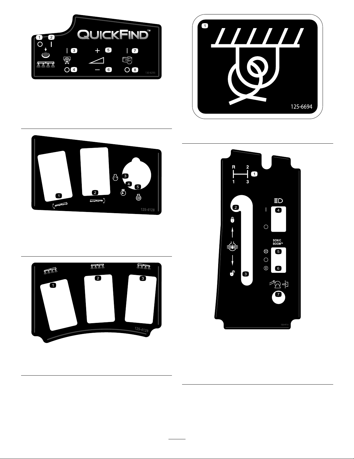
130-8293
1.Sprayeroff
2.Sprayeron
3.Engineon7.Agitationon
4.Engineoff8.Agitationoff
5.Increasespeed
6.Decreasespeed
125–4128
1.Raise/lowerleftboom
2.Raise/lowerrightboom
3.Engine—start
4.Engine—run
5.Engine—stop
125–6694
1.Tiedownlocation
1.Leftboom
2.Centerboom
125–8113
125–4129
3.Rightboom
1.Gearselection5.Automatic(optional)
2.Lockdifferentiallock6.Manual(optional)
3.Unlockdifferentiallock
4.Toggleheadlightson/off
7.Rewindhosereel
(optional)
9
Page 10

125–8114
1.Ratelockout
locked/unlocked
2.Togglerinsepumpon/off
127–3942
1.ReadtheOperator’s
Manualforinformationon
fuses.
2.10A—Ignition7.7.5A
3.15A—Sprayerboom8.2A—TEC
4.15A—Headlights9.30A—Rinsetank
5.7.5A
6.7.5A
1.Parkingbrake
2.Forinformationonstarting
theengine,readthe
Operator’sManual—1)
Engagetheparkingbrake;
2)Insertthekeyintothe
ignition;3)Turnthekeyto
theenginerunposition.
127–3935
3.Forinformationon
stoppingtheengine,read
theOperator’sManual—1)
Pressdownonthebrake
pedal;2)Setthegearto
neutral;3)Engagethe
parkingbrake;4)Release
thebrakepedal;5)Turn
theignitionkeytothe
enginestopposition;6)
Removethekeyfromthe
ignition.
4.Entanglementhazard,
belt—keepawayfrom
movingparts;keepall
guardsandshieldsin
place.
10
Page 11
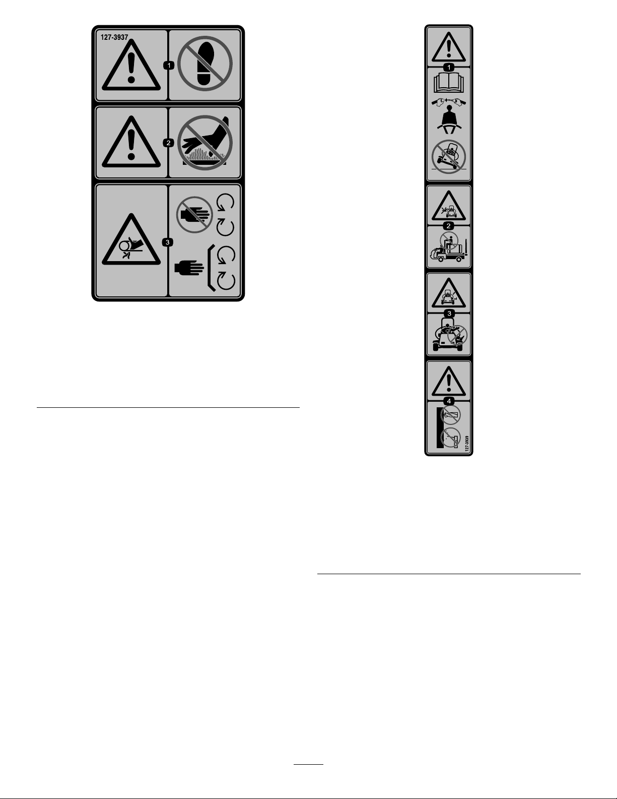
127–3937
1.Warning—donotstep.3.Entanglementhazard,
belt—keepawayfrom
movingparts;keepall
guardsandshieldsin
place.
2.Warning—keepawayfrom
hotsurfaces.
1.Warning—readthe
Operator’sManual;always
wearaseatbeltwhen
operatingthemachine;do
nottipthemachine.
2.Fallinghazard—donot
carrypassengersonthe
sprayertank.
127–3939
3.Cutting/dismemberment
hazard—keeparmsand
legsinsidethevehicleat
alltimes.
4.Warning—donotdrill,
weld,oraltertheROPS
system.
11
Page 12

1.ReadtheOperator’sManual.
127–3938
127–3941
1.Warning—donotoperatethemachinewithoutpropertraining;
readtheOperator’sManual.
2.Warning—keepbystandersawaywhenoperatingthe
machine.
3.Warning—keepawayfrommovingparts;keepallguardsand
shieldsinplace.
4.Electricalshockhazard,overheadpowerlines—checkthe
areaforoverheadpowerlinesbeforeoperatingthemachine
inthearea.
5.Warning—Engagetheparkingbrake,stoptheengine,and
removethekeyfromtheignitionbeforeleavingthemachine.
6.Tippinghazard—Moveslowlywhenthesprayertankisfull;
moveslowlywhendrivingoverroughterrain;donotturnat
highspeed;turnslowly;driveslowlywhendrivingacrossor
upslopes.
12
Page 13

127-6976
1.Decrease2.Increase
127-6982
127-6979
1.Pump-returnow3.Agitationow
2.Flow
1.Bypass-returnow
1.Flow
2.Boomspray
127-6984
2.Tank-returnow
1.Bypass-returnow
2.Flow
127-6981
3.Boomspray
13
Page 14
Setup
tankopeningsothewaterwillarcintothetankwhen
youllit.
Note:Determinetheleftandrightsidesofthemachine
fromthenormaloperatingposition.
1
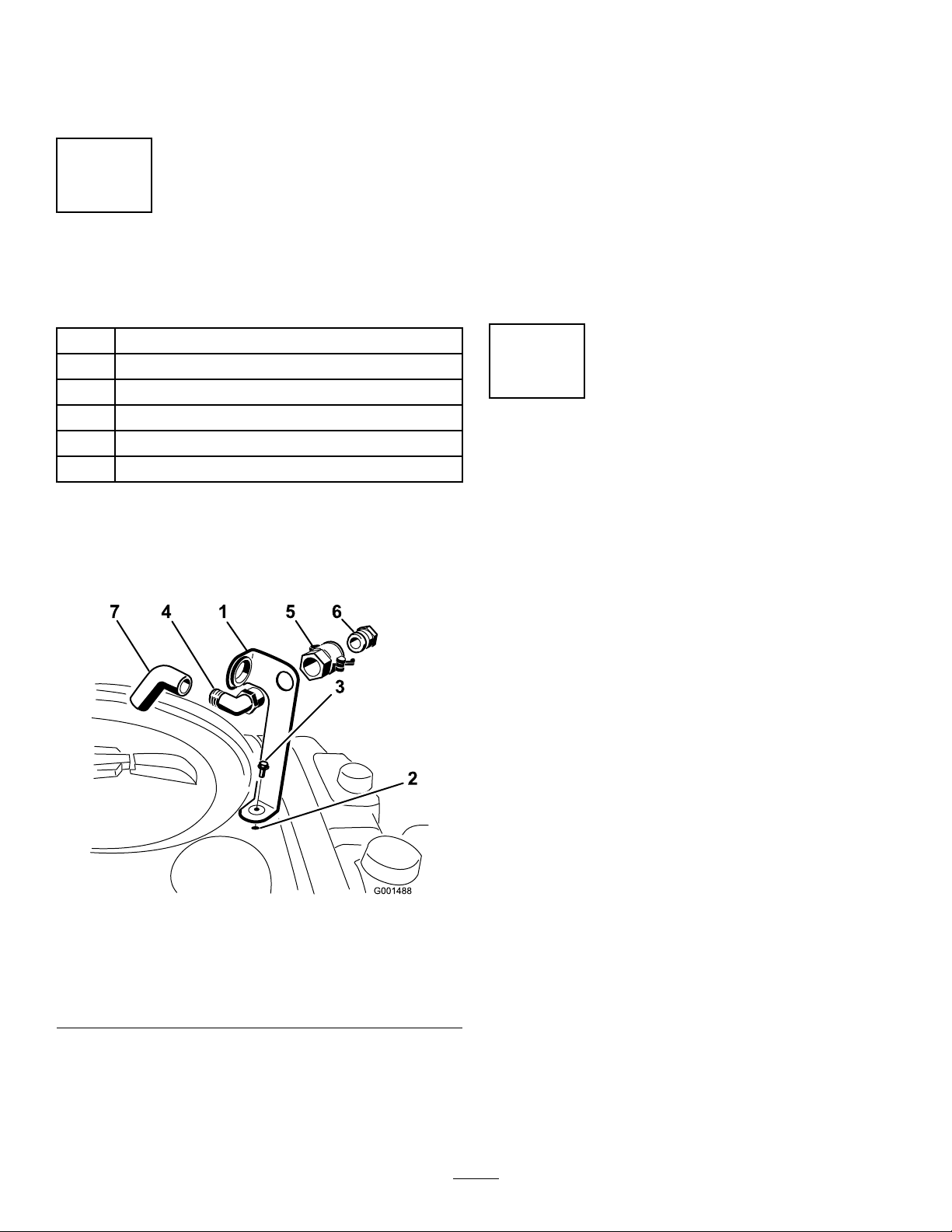
InstallingtheAnti-siphonFill Receptacle
Partsneededforthisprocedure:
1
90°tting
1
Quickcoupler
1Hoseadapter
1Fillreceptaclebracket
1
Flange-headbolt,5/16x3/4inch
1Anti-siphonhose
Procedure
1.Placethellreceptaclebracketoverthethreaded
holeinthetankandsecureitwithaange-headbolt
(5/16x3/4inch)(Figure3).
3.Installthehoseadapterintothequickcoupler(Figure
3).
4.Locktheadapterintoplacebyswingingthelevers
towardtheadapterandthensecurethemwiththe
hairpincotters(Figure3).
5.Installtheanti-siphonhosethroughthelargeopening
onthebracketandontothebarbedendofthe90°
elbowtting(Figure3).
Important:Donotlengthenthehosetoallow
contactwiththetankuids.
2
CheckingtheBoomHinge Springs
NoPartsRequired
Procedure
Important:Operatingthespraysystemwiththeboom
hingespringsundertheincorrectcompressioncould
damagetheboomassembly.Measurethespringsand
usethejamnuttocompressthespringsto4cm(1–1/2
inches)ifnecessary.
Figure3
1.Fillreceptaclebracket
2.Threadedholeinthetank6.Hoseadapter
3.Flangebolt,5/16x3/4inch
4.90°elbowtting
2.Placethethreadedendofthe90°elbowttingthrough
thebracketandthreadthequickcouplerontoit,
securingittothebracket(Figure3).
Note:Installthettingwiththeopenendpointing
towardthelargeopeninginthebracketandtowardthe
5.Quickcoupler
7.Anti-siphonhose
Thesprayerisshippedwiththeboomextensionsswung
forwardtofacilitatepackagingofthemachine.Thesprings
arenotfullytightenedatthetimeofmanufacturetoallowthe
boomstobeinthispositionfortransit.Beforeoperating
themachine,thespringsmustbeadjustedtothecorrect
compression.
1.Ifnecessary,removethepackingcomponentsthat
securetherightandleftextensionboomsduring
shipping.
2.Supporttheboomswhiletheyareextendedtothe
sprayposition.
3.Attheboomhinge,measurethecompressionofthe
upperandlowerspringswhiletheboomsareintheir
extendedposition(Figure4).
A.Allspringsmustbecompresseduntiltheymeasure
4cm(1–1/2inches).
B.Usethejamnuttocompressanyspringthat
measuregreaterthan4cm(1–1/2inches).
14
Page 15
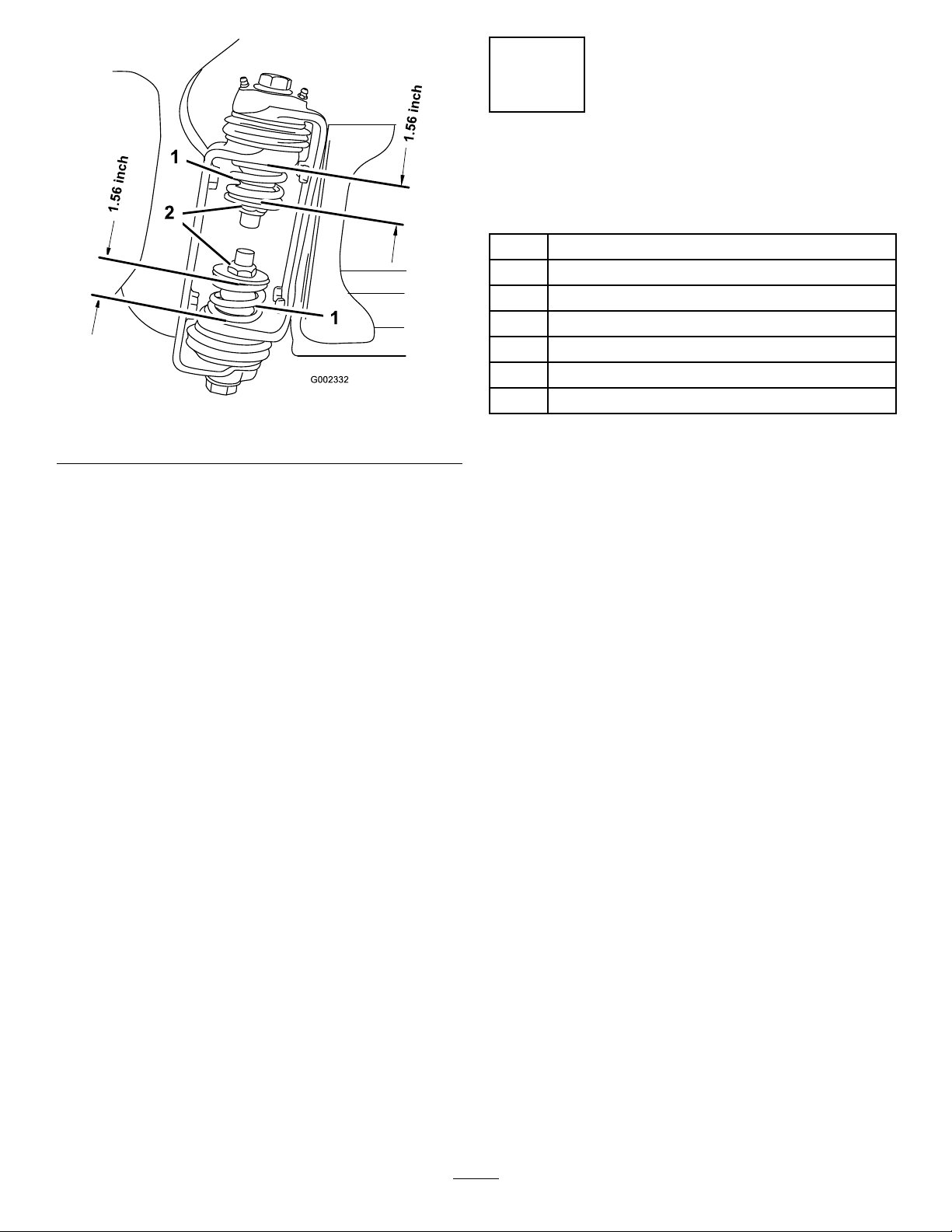
Figure4
1.Boomhingespring2.Jamnut
3
LearningMoreaboutYour Product
Partsneededforthisprocedure:
1Ignitionkey
1
Operator'sManual
1
EngineOperator'sManual
1
PartsCatalog
1
Operatortrainingmaterial
1Registrationcard
1
Pre-deliveryInspectionSheet
Procedure
4.Repeattheprocedureforeachspringonbothboom
hinges.
5.Movetheboomsintothetransport“X”position.See
UsingtheBoomTransportCradle(page26)formore
information.
1.Readthemanuals.
2.Viewtheoperatortrainingmaterial.
3.CompletetheregistrationcardandreturnittoToro.
4.Storethedocumentationinasafeplace.
15
Page 16
ProductOverview
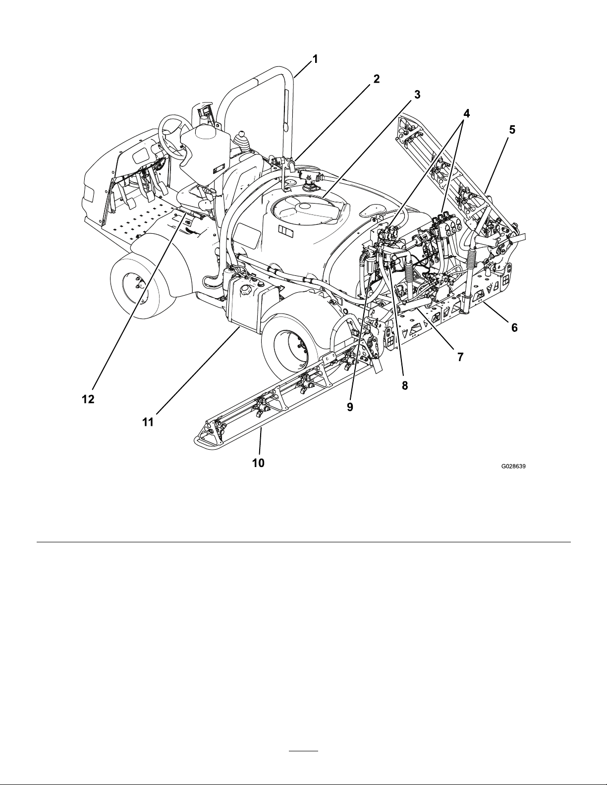
G028 639
1
2
3
4
5
6
7
8
10
11
12
9
Figure5
1.ROPSbar4.Valvemanifolds
2.Anti-siphonreceptacle5.Rightboom8.Agitationthrottlevalve11.Fueltank
3.Chemicaltanklid6.Centerboom9.Pressurelter
7.Boomcontrolcylinder
10.Leftboom
12.Parkingbrake
16
Page 17
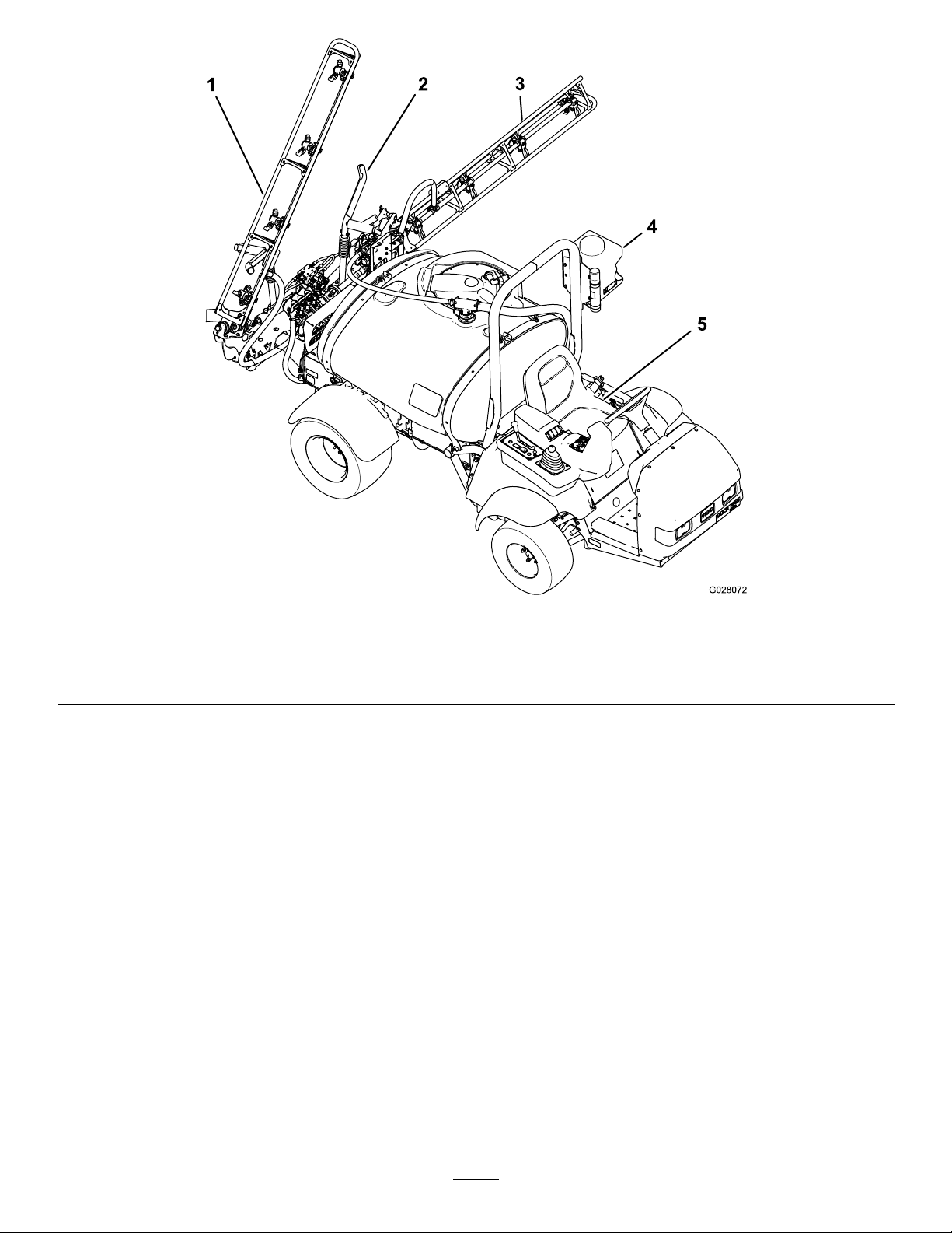
Figure6
1.Rightboom4.Freshwatertank
2.Boomtransportcradle
3.Leftboom
5.Operator’sseat
17
Page 18
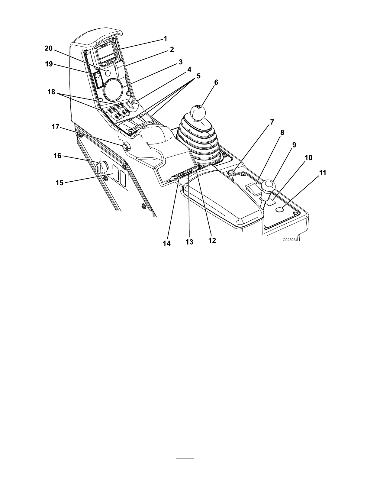
Controls
1.InfoCenter
2.Foammarkerswitch
(optional)
3.Pressuregauge8.Headlightswitch
4.Engineswitch
5.Boom-Sectionswitches10.Sonicboomswitch
6.Rangeselector11.Hosereelrewindbutton
7.Choke
9.Differentiallock
(optional)
Figure7
(optional)
12.Agitationswitch17.Masterboomswitch
13.Spraypressureswitch18.Boomliftswitches
14.Pumpswitch
15.Rinsetankswitch(optional)20.Sonicboomindicator
16.Supervisor(ratelockout)
19.Throttle/speedlockswitch
switch
(optional)
18
Page 19
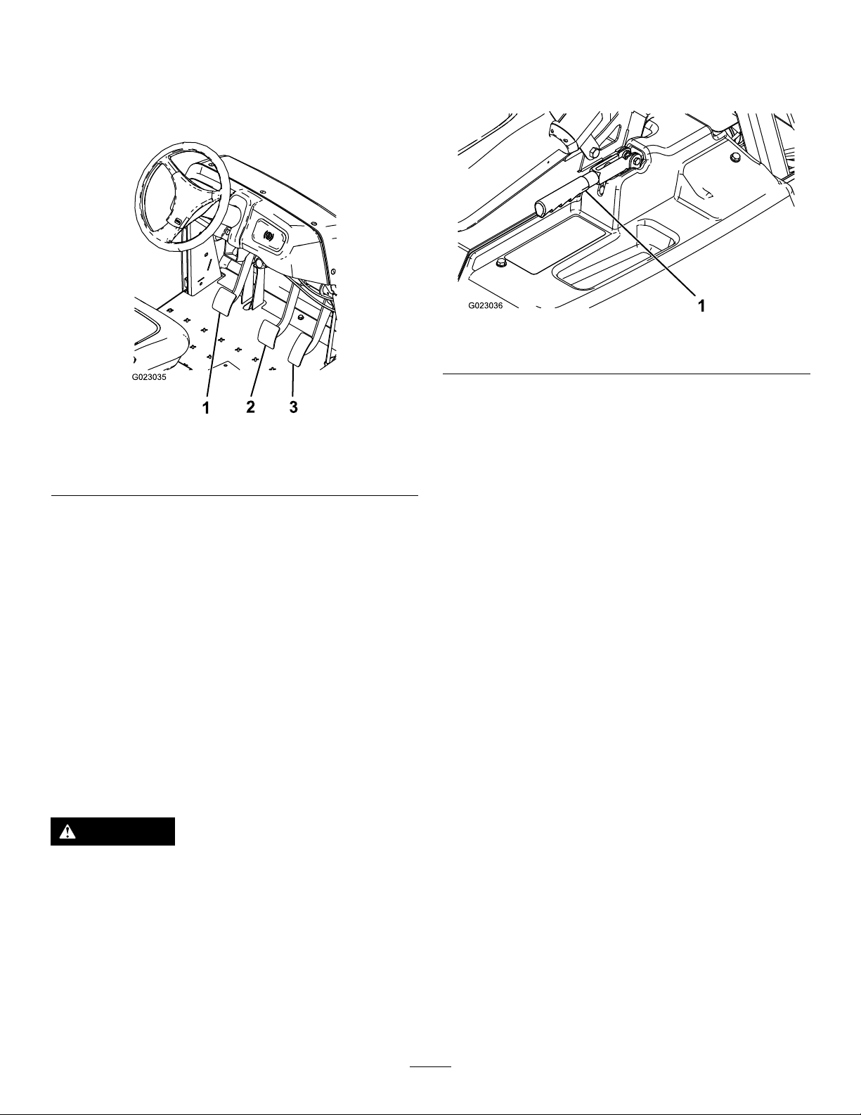
AcceleratorPedal
Theacceleratorpedal(Figure8)givesyoutheabilitytovary
thegroundspeedofthesprayer.Pressingthepedalincreases
groundspeed.Releasingthepedalwillslowthesprayerand
theenginewillidle.
engagetheparkingbrake,pullupandbackonthelever.To
disengage,pushitforwardanddown.Ifthesprayerisparked
onasteepgrade,applytheparkingbrakeandplaceblocksat
thedownhillsideofthewheels.
Figure9
1.Parkingbrakelever
Figure8
1.Clutchpedal
2.Brakepedal
3.Acceleratorpedal
ClutchPedal
Theclutchpedal(Figure8)mustbefullypressedtodisengage
clutchwhenstartingtheengineorshiftingtransmissiongears.
Releasethepedalsmoothlywhenthetransmissionisingear
topreventunnecessarywearonthetransmissionandother
relatedparts.
Important:Donotridetheclutchpedalduring
operation.Theclutchpedalmustbefullyoutorthe
clutchwillslipcausingheatandwear.Neverholdthe
vehiclestoppedonahillusingtheclutchpedal.Damage
totheclutchmayoccur.
BrakePedal
Usethebrakepedaltostoporslowthesprayer(Figure8).
CAUTION
Brakescanbecomewornorcanbeadjusted
incorrectlyresultinginpersonalinjury.
ChokeControl
Thechokecontrolisasmallknobbehindtherangeselector
(Figure7).Tostartacoldengine,pullthechokecontrolup.
Aftertheenginestarts,regulatethechoketokeeptheengine
runningsmoothly.Assoonaspossible,pushthecontrol
downtotheOffposition.Awarmenginerequireslittleor
nochoking.
RangeSelector
Therangeselector(Figure7)has5positions:3forward
speeds,Neutral,andReverse.Theenginewillstartonlywhen
therangeselectorisintheNeutralposition.
IgnitionSwitch
Theignitionswitch(Figure7),usedtostartandstopthe
engine,has3positions:Stop,Run,andStart.Rotatethekey
clockwisetotheStartpositiontostarttheengineandrelease
ittotheRunpositionwhenstarted.Rotatethekeytothe
Stoppositiontostoptheengine.
HeadlightSwitch
Toggletheswitchtooperatetheheadlights(Figure7).Pushit
forwardtoturnthelightsonandrearwardtoturnthemoff.
Ifbrakepedaltravelstowithin2.5cm(1inch)ofthe
sprayeroorboard,adjustorrepairthebrakes.
ParkingBrake
Theparkingbrakeisalargelevertotheleftoftheseat(Figure
9).Engagetheparkingbrakewheneveryouplanonleaving
theseattopreventaccidentalmovementofthesprayer.To
Throttle/SpeedLockSwitch
WhentherangeselectorisintheNeutralposition,youcan
usetheacceleratorpedaltospeeduptheengine,thenpush
theswitchbelowtheInfoCenterforwardtosettheengineat
thatspeed.Thisisnecessarytorunthechemicalagitation
whilestationaryoroperatingattachmentssuchasthehand
sprayer(Figure7).
19
Page 20
Important:TherangeselectormustbeintheNeutral
positionandtheparkingbrakemustbesetfortheswitch
towork.
FuelGauge
Thefuelgaugeislocatedontopofthefueltank,ontheleft
sideofthemachine,andshowstheamountoffuelinthetank.
theInfoCenter.Thehourmeterstartstofunctionwhenever
thekeyisturnedtotheRunposition.
SonicBoom(Optional)
TheSonicBoomswitchisarockerswitchusedtooperate
theSonicBoom.T oggletheswitchforwardforautomatic,
rearwardformanualandcenterforOff.
MasterBoomSwitch
Themasterboomswitch(Figure7)islocatedonthesideof
theconsoleandtotherightoftheoperator.Itallowsyouto
startorstopthesprayoperation.Presstheswitchtoenable
ordisablethespraysystem.
Boom-SectionSwitches
Theboomswitchesarelocatedonthecontrolpanel(Figure
7).Toggleeachswitchforwardtoturnthecorresponding
boomsectiononandrearwardtoturnthemoff.Whenthe
switchisturnedon,alightontheswitchilluminates.These
switcheswillonlyaffectthespraysystemwhenthemaster
boomswitchison.
PumpSwitch
Thepumpswitchislocatedonthecontrolpaneltotheright
oftheseat(Figure7).T ogglethisswitchforwardtorunthe
pumporrearwardtostopthepump.
Important:Thepumpswitchwillonlyengagewhenthe
engineisatlowidletoavoiddamagingthepumpdrive.
FoamMarkerSwitchLocations
(Optional)
IfyouinstalltheFoamMarkerkit,youwilladdswitchesto
thecontrolpanelforcontrollingtheiroperation.Thesprayer
comeswithplasticplugsintheselocations.
Regulating(RateControl)Valve
Thisvalve,locatedbehindthetank(Figure9),controlsthe
amountofuidthatisroutedtotheboomsortheratereturn
tothetank.
ApplicationRateSwitch
Theapplicationrateswitchislocatedonthecontrolpanelto
therightoftheseat(Figure7).Pressandholdtheswitch
forwardtoincreasethespraysystempressure,orpressand
holditrearwardtodecreasethepressure.
Supervisor(RateLockout)Switch
Thesupervisorswitchislocatedonthecontrolpaneltothe
rightoftheseat(Figure7).Turnthekeycounterclockwise
tothelockedpositiontodisabletheapplicationrateswitch,
therebykeepinganyonefromaccidentallychangingthe
applicationrate.Turnthekeyclockwisetotheunlocked
positiontoenabletheapplicationrateswitch.
BoomLift
Theboomliftswitchesarelocatedonthecontrolpaneland
areusedtoraisetheleftandrightboomrespectively.
HourMeter
Thehourmeterindicatesthetotalnumberofhoursthe
enginehasrun.Thisnumberisdisplayedontherstscreenof
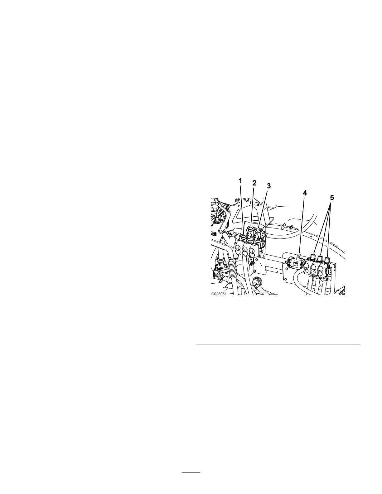
Figure10
1.Regulating(ratecontrol)
valve
2.Agitationvalve5.Boom-sectionvalves
3.Masterboomvalve
4.Flowmeter
MasterBoomValve
Themasterboomvalve(Figure10)isusedtostoptheowto
theowmeterandboomvalves.
Flowmeter
Theowmetermeasurestheowrateoftheuidforuseby
theInfoCentersystem(Figure10).
Boom-SectionValves
Thesevalvesturnthethreeboomsectionsonoroff(Figure
10).
20
Page 21
Boom-SectionBypassValve
Specications
Theboombypassredirectstheuidowforaboomsection
tothetankwhenyouturnofftheboomsection.Y oucan
adjusttheboombypasstoensurethattheboompressure
remainsconstantnomatterhowmanyboomssectionsare
on.RefertoCalibratingtheBoom-SectionBypassValves
(page32).
AgitationValve
Thisvalveislocatedontherearofthetank(Figure10).When
agitationison,theowisdirectedthroughtheagitation
nozzlesinthetank.Whenagitationisoff,theowisdirected
throughthepumpsuction.
PressureGauge
Thepressuregaugeislocatedonthecontrolpanel(Figure7).
Thisgaugeshowsthepressureoftheuidinthesystemin
psiandkPa.
InfoCenterLCDDisplay
TheInfoCenterLCDdisplayshowsinformationaboutyour
machineandbatterypack,suchasthecurrentbatterycharge,
thespeed,diagnosticsinformation,andmore(Figure7).
Note:Specicationsanddesignaresubjecttochange
withoutnotice.
Weightwithstandardspray
system,empty ,without
operator
Weightwithstandardspray
system,full,withoutoperator
Maximumgrossvehicleweight
(GVW)(onlevelground)
Overalllengthwithstandard
spraysystem
Overallheightwithstandard
spraysystem
Overallheightwithstandard
spraysystemtothetopofthe
boomsstoredintheXposition
Overallwidthwithstandard
spraysystemboomsstoredin
theXposition
Groundclearance14cm(5.5inches)
Wheelbase
Tankcapacity(includesthe
CE5%overow)
953kg(2,100lb)
1,678kg(3,700lb)
1,814kg(4,000lb)
343cm(135inches)
191cm(75inches)
246cm(97inches)
178cm(70inches)
155cm(61inches)
662L(175USgallons)
Formoreinformation,refertoUsingtheInfoCenterLCD
Display(page28).
Attachments/Accessories
AselectionofToroapprovedattachmentsandaccessoriesis
availableforusewiththemachinetoenhanceandexpand
itscapabilities.ContactyourAuthorizedServiceDealeror
Distributororgotowww .Toro.comforalistofallapproved
attachmentsandaccessories.
21
Page 22
Operation
AddingFuel
Note:Determinetheleftandrightsidesofthemachine
fromthenormaloperatingposition.
SafetyFirst
Pleasecarefullyreadallofthesafetyinstructionsanddecals
inthesafetysection.Knowingthisinformationcouldhelp
youorbystandersavoidinjury.
PreparingtoDrivetheSprayer fortheFirstTime
CheckingtheEngineOil
Theengineisshippedwithoilinthecrankcase;however,the
levelofoilmustbecheckedbeforeyourststarttheengine
andafteryouhaverunit.
1.Positionthemachineonalevelsurface.
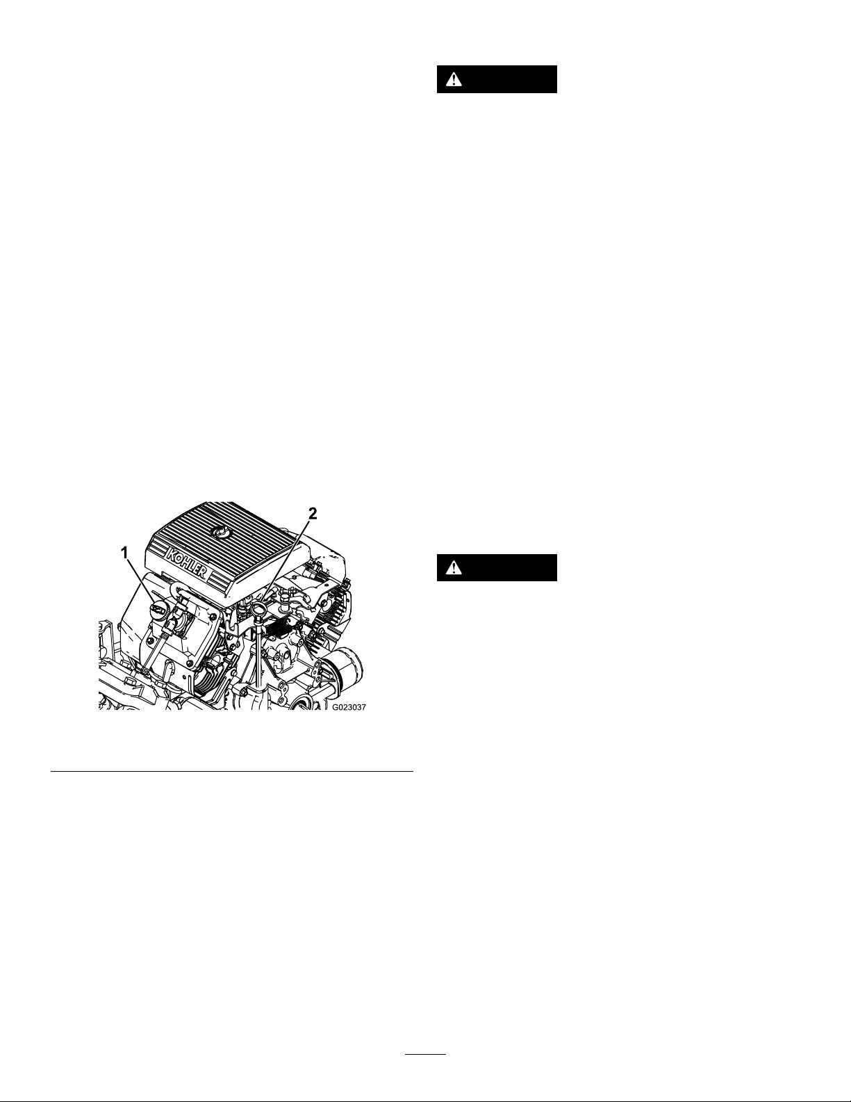
2.Removethedipstickandwipeitwithacleanrag
(Figure11).
3.Insertthedipstickintothetubeandmakesureitis
seatedfully.Removethedipstickandchecktheoillevel.
DANGER
Incertainconditions,gasolineisextremely
ammableandhighlyexplosive.Areorexplosion
fromgasolinecanburnyouandothersandcan
damageproperty.
•Fillthefueltankoutdoors,inanopenarea,
whentheengineiscold.Wipeupanygasoline
thatspills.
•Neverllthefueltankinsideanenclosedtrailer.
•Donotllthefueltankcompletelyfull.Add
gasolinetothefueltankuntilthelevelis6to13
mm(1/4to1/2inch)belowthebottomofthe
llerneck.Thisemptyspaceinthetankallows
gasolinetoexpand.
•Neversmokewhenhandlinggasoline,andstay
awayfromanopenameorwheregasoline
fumesmaybeignitedbyaspark.
•Storegasolineinanapprovedcontainerand
keepitoutofthereachofchildren.Neverbuy
morethana30-daysupplyofgasoline.
•Donotoperatewithoutentireexhaustsystemin
placeandinproperworkingcondition.
Figure11
1.Fillercap2.Dipstick
4.Iftheoillevelislow,removethellercapfromthe
valvecover(Figure11)andpouroilintotheopening
untiltheoillevelisuptotheFullmarkonthedipstick;
refertoChangingtheEngineOil(page40)forthe
properoiltypeandviscosity.Addtheoilslowlyand
checktheleveloftenduringthisprocess.Donot
overll.
5.Installthedipstickrmlyinplace.
CheckingtheTirePressure
Checkthetirepressureevery8hoursordailytoensure
properlevels.Fillthetiresto138kPa(20psi).Also,check
thetiresforwearordamage.
DANGER
Incertainconditionsduringfueling,static
electricitycanbereleasedcausingasparkwhich
canignitethegasolinevapors.Areorexplosion
fromgasolinecanburnyouandothersandcan
damageproperty.
•Alwaysplacegasolinecontainersontheground
awayfromyourvehiclebeforelling.
•Donotllgasolinecontainersinsideavehicleor
onatruckortrailerbedbecauseinteriorcarpets
orplastictruckbedlinersmayinsulatethe
containerandslowthelossofanystaticcharge.
•Whenpractical,removegas-poweredequipment
fromthetruckortrailerandrefueltheequipment
withitswheelsontheground.
•Ifthisisnotpossible,thenrefuelsuch
equipmentonatruckortrailerfromaportable
container,ratherthanfromagasolinedispenser
nozzle.
•Ifagasolinedispensernozzlemustbeused,
keepthenozzleincontactwiththerimofthe
fueltankorcontaineropeningatalltimesuntil
fuelingiscomplete.
22
Page 23
RecommendedFuel
•Forbestresults,useonlyclean,fresh(lessthan30days
old),unleadedgasolinewithanoctaneratingof87or
higher((R+M)/2ratingmethod).
•ETHANOL:Gasolinewithupto10%ethanol(gasohol)
or15%MTBE(methyltertiarybutylether)byvolume
isacceptable.EthanolandMTBEarenotthesame.
Gasolinewith15%ethanol(E15)byvolumeisnot
approvedforuse.Neverusegasolinethatcontainsmore
than10%ethanolbyvolume,suchasE15(contains15%
ethanol),E20(contains20%ethanol),orE85(contains
upto85%ethanol).Usingunapprovedgasolinemay
causeperformanceproblemsand/orenginedamage
whichmaynotbecoveredunderwarranty
•Donotusegasolinecontainingmethanol.
•Donotstorefueleitherinthefueltankorfuelcontainers
overthewinterunlessafuelstabilizerisused.
•Donotaddoiltogasoline.
•Checkalluidlevelsandaddtheappropriateamountof
specieduids,ifanyarefoundtobelow .
•Checkthebrakepedaloperation.
•Checktoseethatthelightsareworking.
•Turnthesteeringwheeltotheleftandrighttocheck
steeringresponse.
•Checkforoilleaks,looseparts,andanyothernoticeable
malfunctions.Makesurethattheengineisoffandall
movingpartshavestoppedbeforecheckingforoilleaks,
looseparts,andothermalfunctions.
Ifanyoftheaboveitemsarenotcorrect,notifyyourmechanic
orcheckwithyoursupervisorbeforetakingthesprayerout
fortheday.Yoursupervisormaywantyoutocheckother
itemsonadailybasis,soaskwhatyourresponsibilitiesare.
DrivingtheSprayer
FillingtheFuelTank
Thefueltankcapacityisapproximately19L(5USgallons).
Note:Thefueltankcapcontainsagaugewhichshowsthe
fuellevel;checkitfrequently.
1.Shuttheengineoffandsettheparkingbrake.
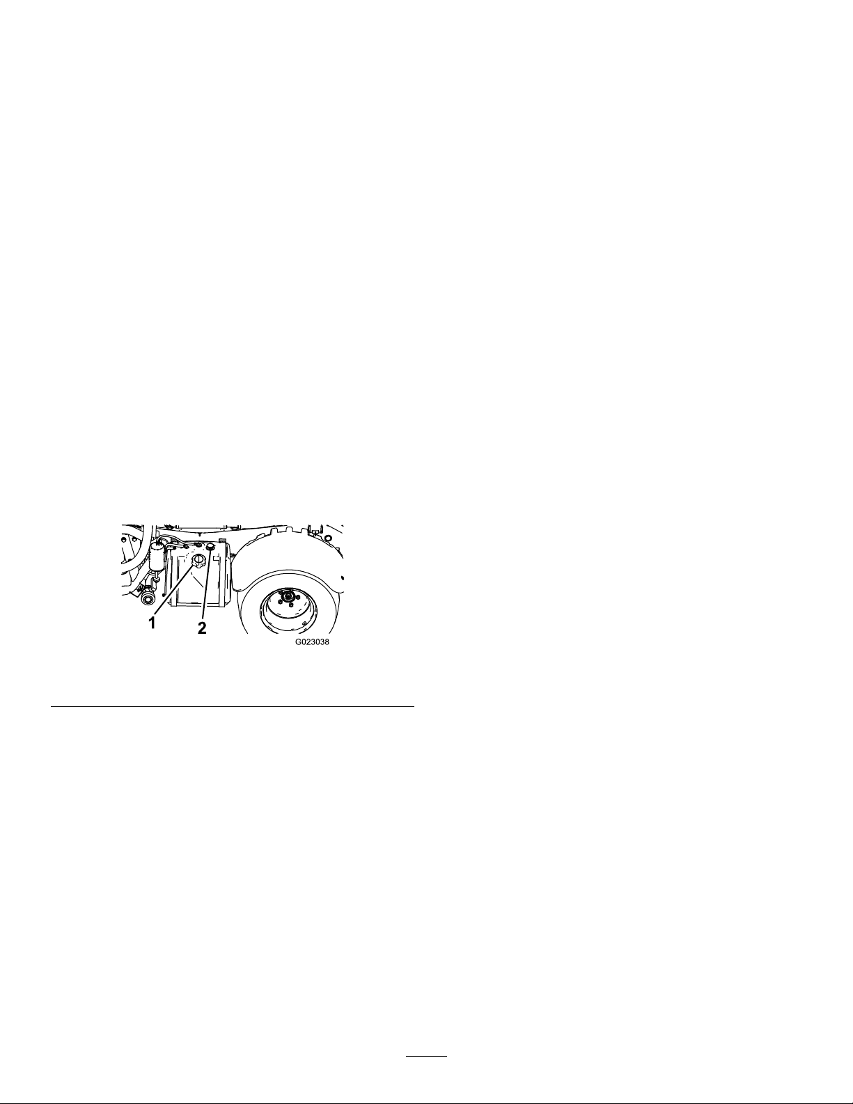
2.Cleantheareaaroundthefuel-tankcap(Figure12).
Figure12
1.Fuel-tankcap2.Fuelgauge
3.Removethefueltankcap.
4.Fillthetanktoaboutoneinchbelowthetopofthe
tank,(bottomofthellerneck).Thisspaceinthetank
allowsgasolinetoexpand.Donotoverll.
5.Installthefuel-tankcapsecurely .
6.Wipeupanyfuelthatmayhavespilled.
StartingtheEngine
1.Sitintheoperator'sseat,insertthekeyintothe
ignitionswitch,androtatethekeyclockwisetotheRun
position.
2.Presstheclutchandmovetherangeselectortothe
Neutralposition.
3.EnsurethatthepumpswitchisintheOffposition.
4.Iftheengineiscold,pullthechokeknobup.
Important:Donotusethechokeiftheengine
iswarm.
5.TurnthekeytotheStartpositionuntiltheenginestarts.
Important:DonotholdthekeyintheStart
positionformorethan10seconds.Iftheengine
hasnotstartedafter10seconds,wait1minute
beforetryingagain.Donotattempttopushortow
thesprayertostarttheengine.
6.Oncetheenginestarts,pushthechokeknobdown
slowly.
Driving
1.Releasetheparkingbrake.
2.Fullypresstheclutchpedal.
PerformingthePre-Starting Checks
Checkthefollowingitemseachtimeyoubeginusingthe
sprayerfortheday:
•Checkthetirepressure.
Note:Thesetiresaredifferentthancartires;theyrequire
lesspressuretominimizeturfcompactionanddamage.
3.Movethegearshiftleverto1stgear.
4.Releasetheclutchpedalsmoothlywhilepressingthe
acceleratorpedal.
5.Whenthevehiclegainsenoughspeed,removeyour
footfromtheacceleratorpedal,fullypresstheclutch
pedal,movethegearshiftlevertothenextgearand
releasetheclutchpedalwhilepressingtheaccelerator
pedal.Repeattheprocedureuntilthedesiredspeedis
attained.
23
Page 24
Important:Alwaysstopthevehiclebeforeshifting
fromaforwardgeartoreverseorfromreversetoa
forwardgear.
5.Removethekeyfromtheswitchtopreventaccidental
starting.
Note:Avoidlongperiodsofengineidling.
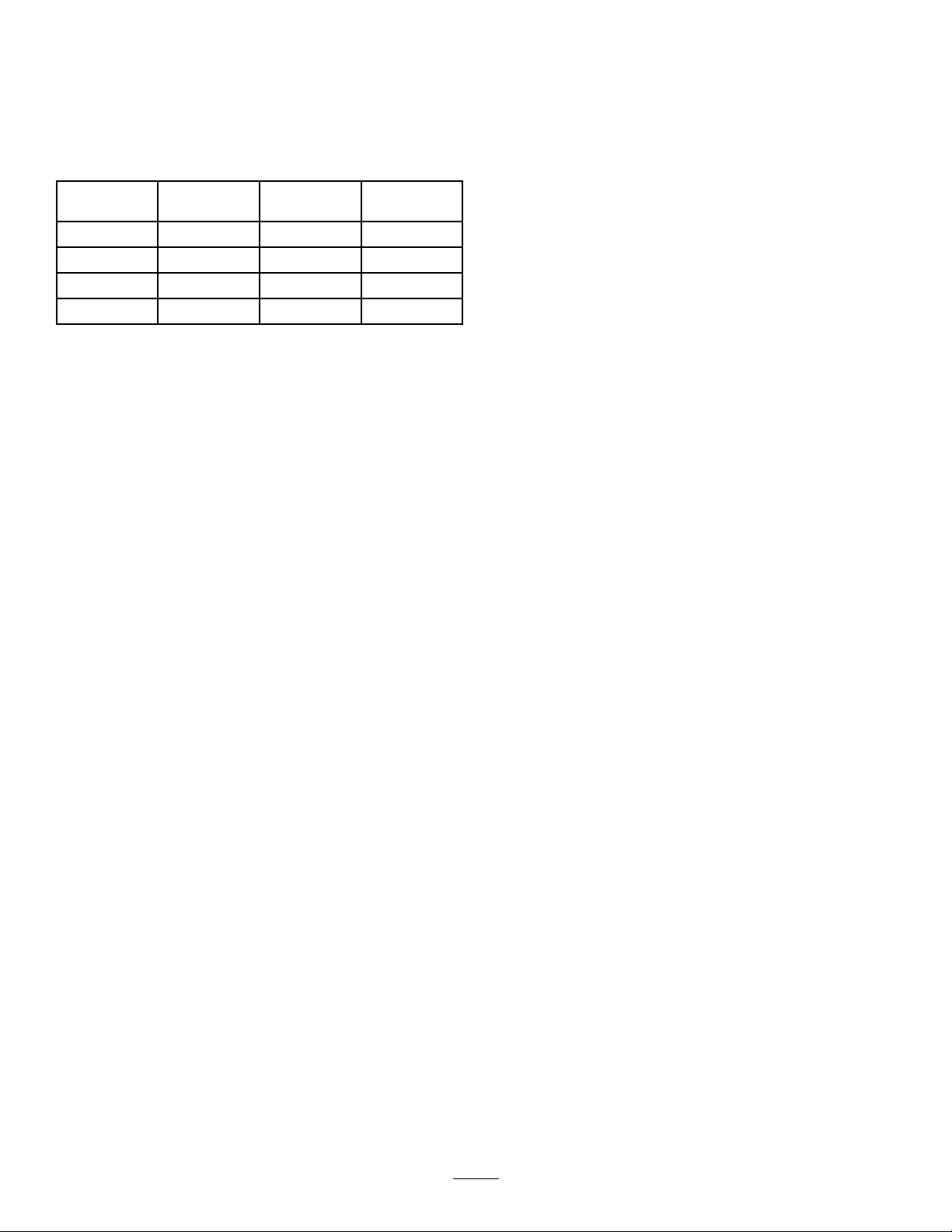
Usethechartbelowtodeterminethegroundspeedof
anemptyvehicleat3400rpm.
Gear
166.4:15.63.5
238.1:19.86.1
319.6:119.211.9
R80.7:14.72.9
Note:LeavingtheignitionswitchintheOnposition
forlongperiodsoftimewithoutrunningtheengine
willdischargethebattery.
Important:Donotattempttopushortowthe
vehicletogetitstarted.Damagetothedrivetrain
couldresult.
Ratio
Speed
(km/h)
Speed(mph)
SettingtheThrottleLock
Note:Theparkingbrakeandspraypumpmustbeonand
therangeselectorinneutraltosetthethrottlelock.
1.Pressdownontheacceleratorpedaltoobtainthe
desiredenginerpm.
2.Togglethethrottlelockswitchonthecontrolpanel
totheOnposition.
3.Toreleasethethrottlelock,toggletheswitchtothe
Offposition,orpressthebrakeorclutchpedal.
BreakinginaNewSprayer
Toprovideproperperformanceandlongsprayerlife,follow
theseguidelinesfortherst100operatinghours:
•Checktheuidandengineoillevelsregularlyandbealert
forindicationsofoverheatinginanycomponentofthe
sprayer.
•Afterstartingacoldengine,letitwarmupforabout
15secondsbeforeaccelerating.
•Tooptimizethebrakesystem,burnish(breakin)the
brakesasfollows:
1.Load454L(120USgallons)ofwaterintothetank.
2.Movethemachinetoandopen-levelarea.
3.Drivethemachineatfullspeed.
4.Applythebrakesrapidly.
Note:Stopthemachineinastraightlinewithout
lockingupthetires.
5.Wait1minutetoallowthebrakestocool.
6.Repeatsteps3through5an9additionaltimes.
•Avoidracingtheengine.
•Varythesprayerspeedduringoperation.Avoidfaststarts
andquickstops.
•RefertotheMaintenance(page35)foranyspecial
low-hourchecks.
SettingtheSpeedLock
Note:Beforesettingthespeedlock,theoperatormustbe
sittingintheoperator’ sseatwiththeparkingbrakeoff,the
pumpon,andtherangeselectoringear.
1.Pressdownontheacceleratorpedaltoobtainthe
desiredenginespeed.
2.Togglethespeedlockswitchonthecontrolpanelto
theOnposition.
3.Toreleasethespeedlock,toggletheswitchtotheOff
position,orpressthebrakeorclutchpedal.
StoppingtheEngine
1.Presstheclutchandapplythebraketostopthesprayer.
2.Pulltheparkingbrakeleverupandbacktosetit.
3.MovetherangeselectoroutofgearintotheNeutral
position.
4.TurntheignitionkeytotheStopposition.
AdjustingtheBoomstoLevel
Thefollowingprocedurecanbeusedtoadjusttheactuators
onthecenterboomtokeeptheleftandrightboomsatlevel.
1.Extendtheboomstothesprayposition.
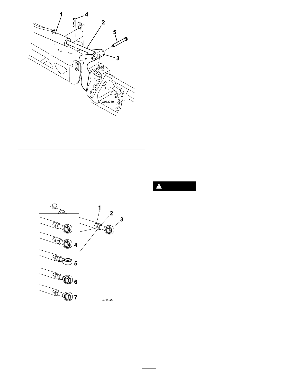
2.Removethecotterpinfromthepivotpin(Figure13).
24
Page 25
G013780
1
4
2
3
5
Figure13
G014220
1
2
3
4
5
6
7
6.Turntheeyeletrodintheactuatorrodtoshortenor
lengthentheextendedactuatortothedesiredposition
(Figure14).
Note:Theeyeletrodmustbeturnedinhalfor
completerevolutionstoallowthereassemblyofthe
rodtotheboom.
7.Oncethedesiredpositionhasbeenachieved,tighten
thejamnuttosecuretheactuatorandeyeletrod.
8.Raisetheboomtoalignthepivotwiththeactuatorrod.
Whileholdingtheboom,insertthepinthroughboth
boompivotandactuatorrod(Figure13).
9.Withthepininplace,releasetheboomandsecurethe
pinwiththecotterpreviouslyremoved.
10.Repeatthisprocedureforeachactuatorrodbearing,
ifnecessary.
1.Actuator
2.Actuatorrod5.Pin
3.Boompivotpinhousing
4.Cotter
3.Liftupontheboomandremovethepin(Figure13),
andslowlylowertheboomtotheground.
4.Inspectthepinforanydamage,andreplaceitif
necessary.
5.Useawrenchontheatsidesoftheactuatorrodto
immobilizeit,thenloosenthejamnuttoallowthe
eyeletrodtobemanipulated(Figure14).
OperatingtheSprayer
TooperatetheMultiProSprayer,rstllthespraytank,
thenapplythesolutiontotheworkarea,andnallycleanthe
tank.Itisimportantthatyoucompleteall3ofthesestepsin
successiontoavoiddamagingthesprayer.Forexample,do
notmixandaddchemicalsinthespraytankatnightandthen
sprayinthemorning.Thiswouldleadtoseparationofthe
chemicalsandtopossibledamagetothesprayercomponents.
CAUTION
Chemicalsarehazardousandcancausepersonal
injury.
•Readthedirectionsonthechemicallabels
beforehandlingthechemicals,andfollow
allmanufacturerrecommendationsand
precautions.
•Keepchemicalsawayfromyourskin.Should
contactoccur,washtheaffectedareathoroughly
withsoapandcleanwater.
•Weargogglesandanyotherprotective
equipmentrecommendedbythechemical
manufacturer.
1.Flatontheactuatorrod5.Eyeletadjusted
2.Jamnut
3.Eyelet7.Jamnuttightenedtolock
4.Jamnutloosened
Figure14
6.Eyeletpositionfor
assembly
newposition
TheMultiProSprayerhasbeenspecicallydesignedtohave
highdurabilityinordertogiveitthelongsprayerlifeyou
need.Differentmaterialshavebeenchosenforspecic
reasonsatdifferentlocationsonyoursprayertomeetthis
goal.Unfortunately,thereisnosinglematerialwhichis
perfectforallforeseeableapplications.
Somechemicalsaremoreaggressivethanothers,andeach
chemicalinteractsdifferentlywithvariousmaterials.Some
consistencies(e.g.wettablepowders,charcoal)aremore
abrasiveandleadtohigher-than-normalwearrates.Ifa
chemicalisavailableinaformulationthatwouldprovide
increasedlifetothesprayer,usethisalternativeformulation.
25
Page 26

Asalways,remembertocleanyoursprayerthoroughlyafter
allapplications.Thiswilldothemosttoensurethatyour
sprayerhasalongandtrouble-freelife.
FillingtheFreshWaterTank
Important:Ifyouareusingawettablepowder
withoutfullagitation,mixthepowderwithasmall
amountofwatertoformaslurrybeforeadding
ittothetank.
11.Addtheremainingwatertothetank.
Alwaysllthefreshwatertankwithcleanwaterbefore
handlingormixinganychemicals.
ThefreshwatertankislocatedontheleftsideoftheROPS
bar.Itsuppliesasourceoffreshwaterforyoutowash
chemicalsoffofyourskin,eyes,orothersurfacesinthecase
ofaccidentalexposure.
Toopenthefreshwatertankspigot,turntheleveronthe
spigot.
FillingtheSprayTank
InstalltheChemicalPre-MixKitforoptimalmixingand
exteriortankcleanliness.
Important:Ensurethatthechemicalsyouwillbeusing
arecompatibleforusewithViton(seethemanufacturer's
label;itshouldindicateifitisnotcompatible).Usinga
chemicalthatisnotcompatiblewithVitonwilldegrade
theO-ringsinthesprayer,causingleaks.
Important:V erifythattheproperapplicationratehas
beensetpriortollingthetankwithchemicals.
1.Stopthesprayeronalevelsurface,movetherange
selectortotheNeutralposition,stoptheengine,and
settheparkingbrake.
2.Ensurethatthetankdrainvalveisclosed.
3.Determinetheamountofwaterneededtomixthe
amountofchemicalyouneedasprescribedbythe
chemicalmanufacturer.
4.Openthetankcoveronthespraytank.
Note:Thetankcoverislocatedinthecenterofthe
topofthetank.Toopenit,turnthefronthalfofthe
covercounterclockwiseandswingitopen.Youcan
removethestrainerinsideforcleaning.Tosealthe
tank,closethecoverandrotatethefronthalfclockwise.
5.Add3/4oftherequiredwatertothespraytankusing
theanti-siphonllreceptacle.
Important:Alwaysusefreshcleanwaterinthe
spraytank.Donotpourconcentrateintoanempty
tank.
6.StarttheengineandsetthepumpswitchtotheOn
position.
7.Presstheacceleratorpedaltotheoorandsetthe
throttlelocktotheOnposition.
8.SetthemasterboomswitchtotheOffposition.
9.TurntheagitationvalvetotheOnposition.
10.Addtheproperamountofchemicalconcentratetothe
tankasdirectedbythechemicalmanufacturer.
OperatingtheBooms
Theboomliftswitchesonthesprayercontrolpanelallows
youtomovetheboomsbetweentransportpositionand
spraypositionwithoutleavingtheoperator'sseat.Itis
recommendedtochangeboompositionswhilethemachine
isstationary.
ChangingtheBoomPosition
1.Stopthesprayeronlevelground.
2.Usetheboomliftswitchestolowerthebooms.
Note:Waituntiltheboomsreachthefull,extended
sprayposition.
3.Whentheboomsneedtoberetracted,stopthesprayer
onlevelground.
4.Usetheboomliftswitchestoraisethebooms,until
theyhavemovedcompletelyintoboomtransport
cradleformingthe“X”transportpositionandthe
boomcylindersarefullyretracted.
Important:T opreventdamagetotheboom
actuatorcylinder,makesurethattheactuatorsare
fullyretractedbeforetransport.
UsingtheBoomTransportCradle
Thesprayerisequippedwithaboomtransportcradlethat
hasauniquesafetyfeature.Intheeventofaccidentalboom
contactwithalowoverheadobjectwhileinthetransport
position,theboom(s)canbepushedoutofthetransport
cradles.Ifthisoccurs,theboomswillcometorestina
nearhorizontalpositiontotherearofthevehicle.While
theboomswillnotbedamagedduetothismovement,they
shouldbeimmediatelyputbackintothetransportcradle.
Important:Theboomscanbedamagedbytransporting
theminanypositionotherthanthe“X”transport
positionusingtheboomtransportcradle.
Toputtheboomsbackintothetransportcradle,lowerthe
boom(s)tothesprayposition,andthenraisetheboom(s)
backintothetransportposition.Makesurethattheboom
cylindersarefullyretractedtopreventactuatorroddamage.
Spraying
Important:T oensurethatyoursolutionremainswell
mixed,usetheagitationfeaturewheneveryouhavea
solutioninthetank.Foragitationtowork,thepump
mustbeonandtheenginemustberunningabovean
idle.Ifyoustopthevehicleandneedagitationon:
settheparkingbrake,turnthepumpOn,pressthe
26
Page 27
acceleratorpedaltooor,andswitchthethrottlelockto
theOnposition.
Note:Thisprocedureassumesthatthepumpisonfromthe
FillingtheSprayTank(page26)procedure.
1.Lowertheboomsintoposition.
2.WiththemasterboomswitchintheOffposition,set
the3boomswitchestotheOnposition.
3.Drivetothelocationwhereyouwillbespraying.
4.SetthemasterboomswitchtotheOnpositionto
beginspraying.
Note:TheInfoCenterwillshowtheboomswiththe
sprayon.
Note:Whenthetankisnearlyempty,theagitation
maycausefoaminginthetank.Topreventthis,turn
theagitationvalveoff.Alternatively ,youcanusean
anti-foamingagentinthetank.
5.Usetherateswitchtoadjustandsetatarget.
6.Whennishedspraying,setthemasterboomswitch
totheOffpositiontoturnoffallbooms,thensetthe
pumpswitchtotheOffposition.
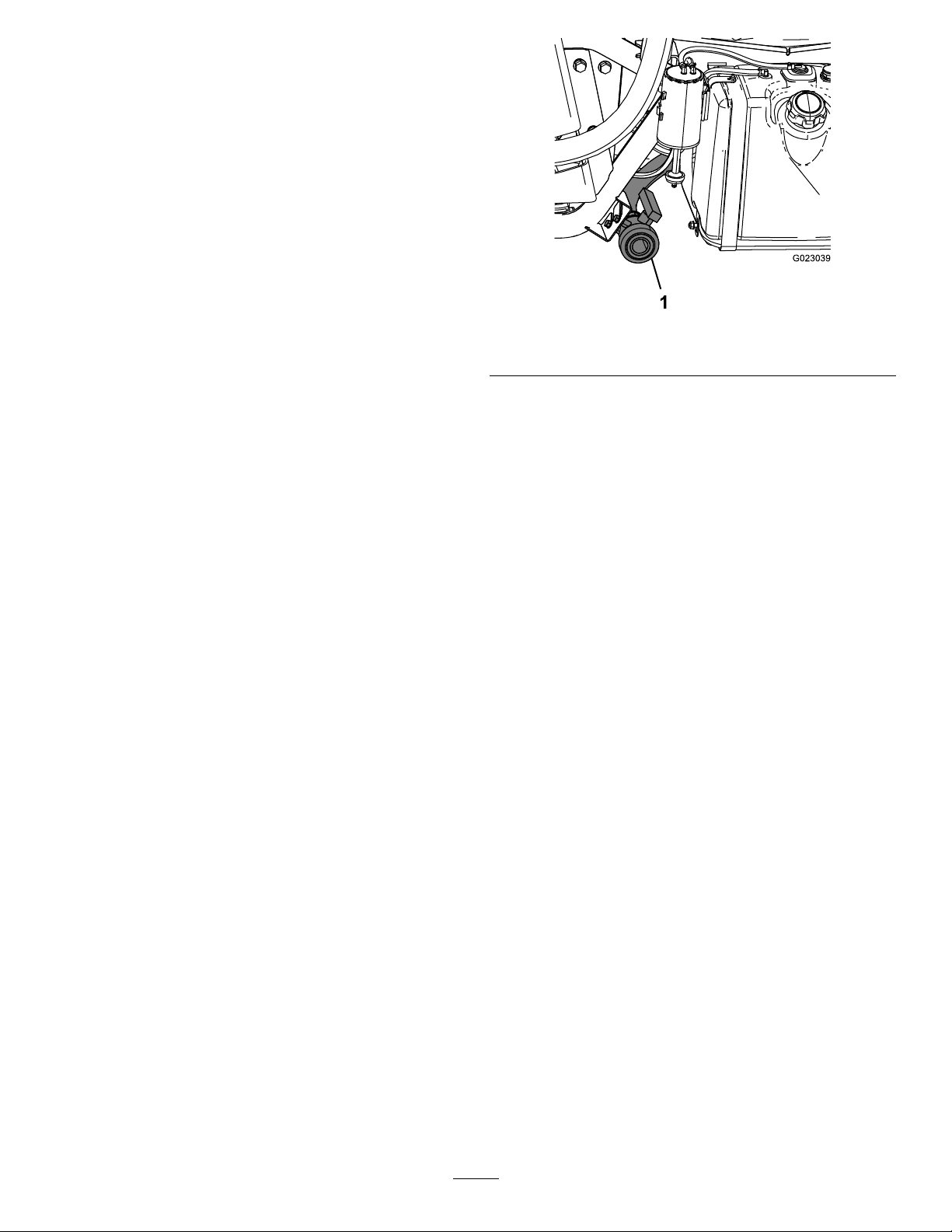
Figure15
1.Tankdrain
3.Removethevalvefromthebracket,andletthevalve
restontheground.
4.Openthevalvetodrainanyunusedmaterialfromthe
tankanddisposeofitaccordingtolocalcodesandthe
materialmanufacturer'sinstructions(Figure15).
SprayingTips
•Donotoverlapareasthatyouhavepreviouslysprayed.
•Watchforpluggednozzles.Replaceallwornordamaged
nozzles.
•Usethemasterboomswitchtostopthesprayow
beforestoppingthesprayer.Oncestopped,placethe
rangeselectorintheNeutralpositionandusetheneutral
enginespeedlocktoholdtheenginespeeduptokeep
theagitationrunning.
•Youwillobtainbetterresultsifthesprayerismoving
whenyouturntheboomson.
•Watchforchangesintheapplicationratethatmay
indicatethatyourspeedhaschangedbeyondtherangeof
thenozzlesorthereisaproblemwiththespraysystem.
CleaningtheSprayer
Important:Y oumustalwaysemptyandcleanthe
sprayerimmediatelyaftereachuse.Failuretodoso
maycausethechemicalstodryorthickeninthelines,
cloggingthepumpandothercomponents.
Note:InstalltheTankCleanRinseKitforoptimaltank
cleaning.
1.Stopthesprayer,settheparkingbrake,placetherange
selectorintheNeutralposition,andturnofftheengine.
Thetankwilldraintotheleftsideofthemachine.
2.Locatethetankdrainvalveontheleftsideofthe
machine(Figure15).
Note:Thevalveisbehindtheleftfenderbracketnext
tothefueltank.
Note:Thisallowsanyresidualmaterialinthelineto
drain.
5.Whenthetankhasdrainedcompletely,closethedrain
valveandinstallthevalveontothebracket(Figure15).
6.Rinsetheinsideofthetankwithatleast22L(6US
gallons)ofcleanfreshwaterandclosethecover.
Note:Youcanuseacleaning/neutralizingagentin
thewaterasneeded.Onthenalrinse,useonlyclean,
clearwater.
7.Starttheengine.
8.SetthepumpswitchtotheOnpositionandusethe
applicationrateswitchtoincreasethepressuretoa
highsetting.
9.WiththerangeselectorintheNeutralposition,press
theacceleratorpedaltotheoorandtogglethethrottle
lockswitchtotheOnposition.
10.EnsurethattheagitationvalveisintheOnposition.
11.Setthemasterboomswitchandboomcontrolswitches
totheOnpositiontobeginspraying.
12.Allowallofthewaterinthetanktosprayoutthough
thenozzles.
13.Checkthenozzlestoensurethattheyareallspraying
correctly.
14.SetthemasterboomswitchtotheOffposition,setthe
pumpswitchtotheOffposition,andstoptheengine.
15.Repeatsteps6through14atleast2moretimesto
ensurethatthespraysystemisfullycleaned.
16.Onthelastcycle,runthelastfewgallonsofwater
throughthedrainvalvetoclearthedraintubing.
27
Page 28
17.Cleanthestrainer;refertoCleaningtheSuction
1
g020650
2
3
4
TORO
Strainer(page52).
Important:Ifyouusedwettablepowder
chemicals,cleanthestraineraftereachtank.
18.Usingagardenhose,sprayofftheoutsideofthe
sprayerwithcleanwater.
19.Removethenozzlesandcleanthembyhand.
Note:Replacedamagedorwornnozzles.
UsingtheInfoCenterLCD Display
TheInfoCenterLCDdisplayshowsinformationaboutyour
machine,suchastheoperatingstatus,variousdiagnostics,
andotherinformationaboutthemachine(Figure16).
Thereisasplashscreenandmaininformationscreenon
theInfoCenter.Youcanswitchbetweenthesplashscreen
andmaininformationscreenatanytimebypressinganyof
theInfoCenterbuttonsandthenselectingtheappropriate
directionalarrow .
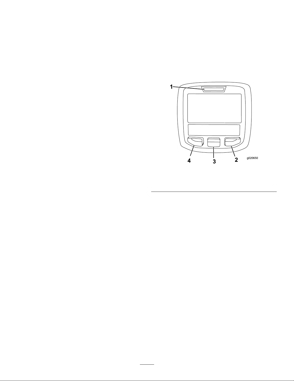
Figure16
1.Indicatorlight3.Middlebutton
2.Rightbutton
4.Leftbutton
•Leftbutton,Menuaccess/Backbutton—pressthis
buttontoaccesstheInfoCentermenus.Youcanalsouse
ittobackoutofanymenuthatyouarecurrentlyusing.
•Middlebutton—usethisbuttontoscrolldownmenus.
•Rightbutton—usethisbuttontoopenamenuwherea
rightarrowindicatedadditionalcontent.
Note:Thepurposeofeachbuttonmaychangedepending
onwhatisrequiredatthetime.Eachbuttonwillhaveanicon
displayingitscurrentfunction.
28
Page 29
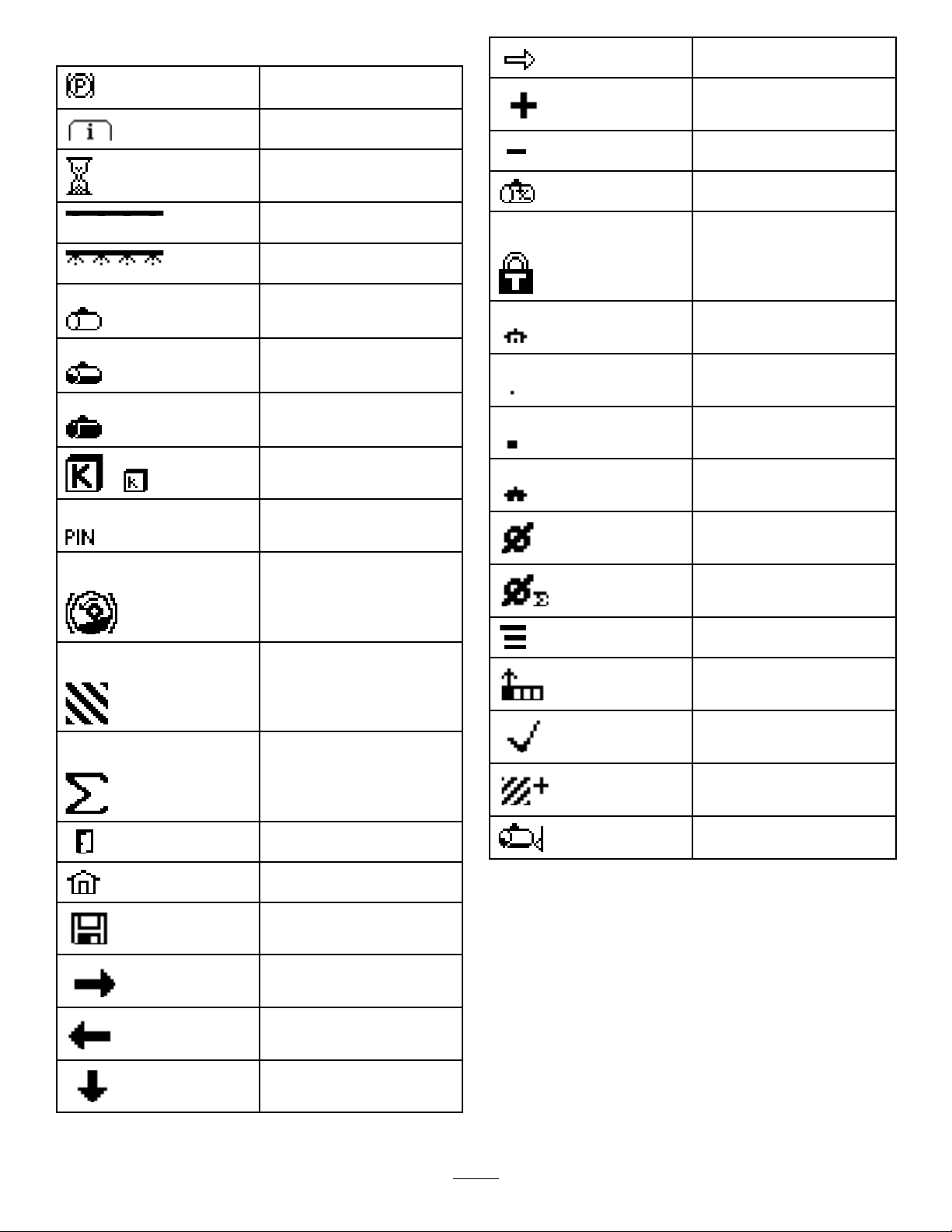
InfoCenterIconDescriptions
Enter
Parkingbrakeactive
Informationicon
Hourmeter
MasterboomOn/Boom
sectionOff
MasterboomOn/Boom
sectionOn
Emptyspraytank
Spraytankathalf
Fullspraytank
TURFunits(1,000square
or
feet)
CorrectPINcodeentered
Increase
Decrease
Adjusttankvolume
Throttlelockisactive
Homescreen
Inactivescreen
Activescreen
Activehomescreen
Clearactivearea
Hill-assist
Areasprayed
Volumesprayed
Exitmenu
Gotothehomescreen
Savevalue
Next
Clearallareas
Changethenextvalueinthe
list
Adjustdigit
CheckPINentry/Calibration
verication
Selectthenextareafor
accumulation
Tanklevellow
Previous
Scrolldown
29
Page 30
UsingtheMenus
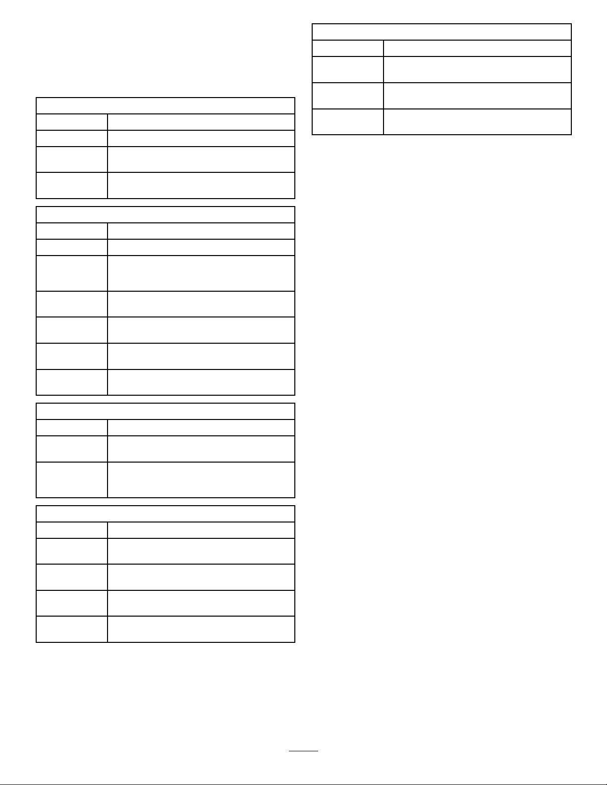
ToaccesstheInfoCentermenusystem,pressthemenuaccess
buttonwhileatthemainscreen.Thiswillbringyoutothe
mainmenu.Refertothefollowingtablesforasynopsisof
theoptionsavailablefromthemenus:
Calibration
MenuItemDescription
TestSpeedThismenusetsthetestspeedforcalibration.
Flow
Calibration
Speed
Calibration
Thismenucalibratestheowmeter.
Thismenucalibratesthespeedsensor.
AboutMenu
MenuItemDescription
Model
SerialNumberThismenuliststheserialnumberofthe
S/WRev.Thismenuliststherevisionnumberofthe
Thismenuliststhemodelnumberofthe
machine.
machine.
machinesoftware.
Note:Ifyouinadvertentlychangethelanguageorcontrast
toasettingwhereyoucannolongerunderstandorview
thedisplay ,contactyourAuthorizedToroDistributorfor
assistanceinresettingthedisplay.
SettingsMenu
MenuItemDescription
LowTankAlertThismenusetsthelowtankvolumealert.
UnitsThismenuchangestheunitsusedbythe
LanguageThismenuchangesthelanguageusedon
LCDBacklight
LCDContrast
Protected
Menus
ServiceMenu
MenuItemDescription
Faults
Hours
DiagnosticsMenu
MenuItemDescription
PumpsThismenuaccessesthepumpinputs,
BoomsThismenuaccessestheboominputs,
ThrottleLockThismenuaccessesthethrottlelockinputs,
EngineRunThismenuaccessestheengineruninputs
InfoCenter.ThemenuchoicesareEnglish,
SI(Metric),andTurf.
theInfoCenter.
Thismenuincreasesordecreasesthe
brightnessoftheLCDdisplay.
Thismenuchangesthecontrastbetweenthe
darkandlightareasoftheLCDdisplay.
Thismenugrantsaccesstoprotectedmenus.
Thismenudisplaysthemostrecentfaults
andlastclearedfault.
Thismenuliststhetotalnumberofhoursfor
keyon,machinerun,andpumpon.Italso
liststheserviceduehourandservicereset.
momentaryrinse,andtimerinseoptions.
qualiers,andoutputs.
quantiers,andoutputs.
andoutputs.
CalibratingtheSprayerFlow
Operatorsuppliedequipment:Stopwatchcapableof
measuring±1/10secondandacontainergraduatedin50
ml(1-oz)increments.
Note:Beforeusingthesprayerforthersttime,ifyou
changethenozzles,orasneeded,calibratethesprayerow ,
speed,andboombypass.
1.Fillthespraytankwithcleanwater.
Note:Ensurethatthereisenoughwaterinthetankto
completethecalibration.
2.Settheparkingbrakeandturntheengineon.
3.SetthepumpswitchtotheOnposition,andturnon
theagitation.
4.Pressdownontheacceleratorpedaluntilyoureachthe
maximumenginespeed,andtogglethethrottlelock
switchtotheOnposition.
5.Setall3boomswitchesandthemasterboomswitch
totheOnposition.
6.Turnthesupervisor(ratelockout)switchtotheUnlock
position.
7.Preparetoperformacatchtestusingthegraduated
container.
30
Page 31

8.Startat40psi(2.75bar)andusetheapplicationrate
switchtoadjustthespraypressuresoacatchtestyields
theamountslistedinthetablebelow .
14.Aftertheveminutedurationofsprayingclickthe
checkmarkbypressingthecenterbuttonontheinfo
center.
Note:Repeatthetest3timesandusetheaverage.
NozzleColor
Yellow1896.4
Red37812.8
Brown47316.0
Gray
White
Blue94632.0
Green
Milliliters
collectedin15
seconds
56719.2
757
1,41948.0
Ouncescollected
in15seconds
25.6
9.Oncethecatchtesthasyieldedtheamountslistedin
thetableabove,setthesupervisorratelockoutswitch
totheLockposition.
10.Turnoffthemasterboomswitch.
11.OntheInfoCenter,navigatetotheCalibrationmenu
andselectFlowCalibrationasfollows:
Note:SelectingtheHomeScreeniconatanytimewill
cancelcalibrations.
A.Pressthecenterbuttonoftheinfocentertwiceto
accessthemenus.
B.EnterthecalibrationmenubypressingtheRH
buttonontheinfocenter.
C.SelectFlowCalbyhighlightingFlowCaland
presstheRHbuttonontheInfoCenter.
D.Inthenextscreen,entertheknownquantityof
waterthatwillbesprayedoutoftheboomsfor
thecalibrationprocedure;refertothechartbelow.
Note:Itisacceptableifthegallonsdisplayedduring
thecalibrationprocessdonotmatchtheknown
quantityofwaterenteredintotheInfoCenter.
15.After5minutes,turnoffthemasterboomswitchand
selectthecheckmarkontheInfoCenter.
Note:Calibrationisnowcomplete.
CalibratingtheSprayerSpeed
Note:Beforeusingthesprayerforthersttime,ifyou
changethenozzles,orasneeded,calibratethesprayerow ,
speed,andboombypass.
1.Fillthetankwithfreshwater.
2.Onanopen,atarea,markoffadistancebetween
45–152m(150–500ft).
Note:T ororecommendsmarkingoff152m(500ft)
formoreaccurateresults.
3.Starttheengineanddrivetothestartofthemarked-off
distance.
Note:Alignthecenterofthefronttireswiththe
startinglineforthemostaccuratemeasurement.
4.OntheInfoCenter,navigatetotheCalibrationmenu
andselectSpeedCalibration.
Note:SelectingtheHomeScreeniconatanytimewill
cancelcalibrations.
5.SelecttheNextarrow(→)ontheInfoCenter.
6.Usingtheplus(+)andminus(-)symbols,enterthe
marked-offdistanceintotheInfoCenter.
E.Oncetheknownquantityhasbeenenteredpress
theRHbuttonontheinfocenter.
12.Usingtheplus(+)andminus(-)symbols,enterthe
owvolumeaccordingtothetablebelow.
NozzleColor
Yellow421 1
Red8322
Brown10628
Gray
White16744
Blue208
Green
Liters
12533
31483
USGallons
55
13.Turnonthemasterboomswitchfor5minutes.
Note:Asthemachinesprays,theinfocenterwill
displaythequantityofuidit'scounting.
7.Shiftthemachineintorstgearanddrivethemarked
distanceinastraightlineatfullthrottle.
8.Stopthemachineatthemarked-offdistanceandselect
thecheckmarkontheInfoCenter.
Note:Slowdownandrolltoastoptoalignthecenter
ofthefronttireswiththenishline,forthemost
accuratemeasurement.
Note:Calibrationisnowcomplete.
31
Page 32
CalibratingtheBoom-Section BypassValves
Note:Beforeusingthesprayerforthersttime,ifyou
changethenozzles,orasneeded,calibratethesprayerow ,
speed,andboombypass.
Selectanopenatareatoperformthisprocedure.
1.Fillthespraytankhalfwaywithcleanwater.
2.Lowerthesprayerbooms.
3.MovetherangeselectortotheNeutralposition,and
settheparkingbrake.
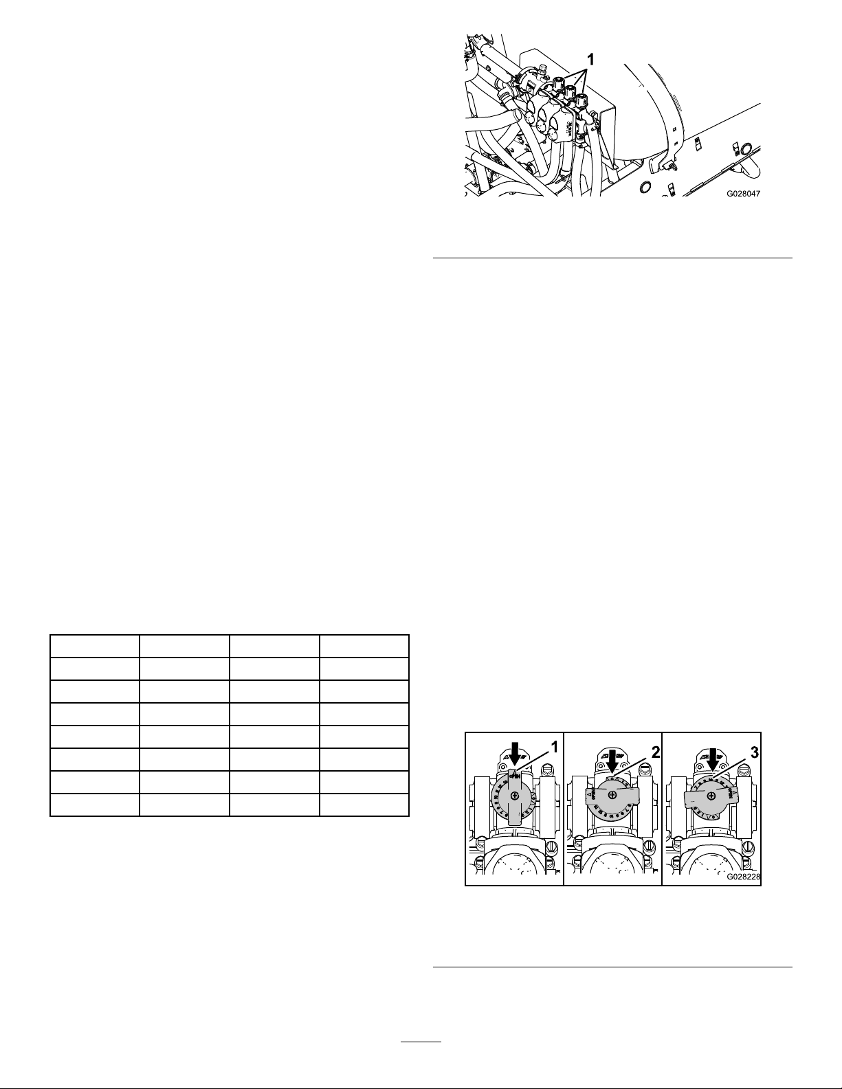
Figure17
1.Boom-sectionbypassadjustmentknobs
4.Setthe3boomswitchestotheOnposition,butleave
themasterboomswitchoff.
5.SetthepumpswitchtotheOnposition,andturnon
theagitation.
6.Pressdownontheacceleratorpedaluntilyoureachthe
maximumenginespeed,andtogglethethrottlelock
switchtotheOnposition.
7.OntheInfoCenter,navigatetotheCalibrationmenu
andselectTestSpeed.
Note:SelectingtheHomeScreeniconatanytimewill
cancelcalibrations.
8.Usingtheplus(+)andminus(-)symbols,enteratest
speedof5.6Km/h(3.5mph),thenselecttheHome
icon.
9.Turnthesupervisor(ratelockout)switchtotheUnlock
position,andturnthemasterboomswitchon.
10.Usingtheapplicationrateswitch,adjusttheapplication
rateaccordingtothetablebelow.
NozzleColorSI(Metric)
Yellow
Red
Brown
Gray766l/ha
White
Blue
Green1,917l/ha
237l/ha
509l/ha
638l/ha
1,019l/ha
1,276l/ha
English
17gpa0.39gpk
34gpa0.78gpk
42gpa0.97gpk
51gpa1.17gpk
68gpa1.55gpk
85gpa1.94gpk
127gpa2.91gpk
Turf
12.Turnontheleftboomandturnofftherightboom.
13.Adjusttherightboombypassknob(Figure17)until
thepressurereadingisatthepreviouslyadjustedlevel
(typically40psior2.75bar).
14.Turnontherightboomandturnoffthecenterboom.
15.Adjustthecenterboombypassknob(Figure17)until
thepressurereadingisatthepreviouslyadjustedlevel
(typically40psior2.75bar).
16.Turnalltheboomsoff.
17.Turnthepumpoff.
Note:Calibrationisnowcomplete.
AgitationBypassValveKnob Position
•TheagitationbypassvalveisinthefullOpenpositionas
showninAofFigure18.
•TheagitationbypassvalveisintheClose(0)positionas
showninBofFigure18.
•Theagitationbypassvalveisinanintermediate(adjusted
relativetothepressuregaugeforthesprayersystem)
positionasshowninCofFigure18
11.Turnofftheleftboomandadjusttheboombypass
knob(Figure17)untilthepressurereadingisatthe
previouslyadjustedlevel(typically40psior2.75bar).
Note:Thenumberedindicatorsonthebypassknob
andneedleareforreferenceonly .
32
1.Open
2.Closed(0)
Figure18
3.Intermediateposition
Page 33
CalibratingtheAgitation
1
2
g018934
AdjustingtheMasterBoom
BypassValve
ServiceInterval:Y early
Selectanopenatareatoperformthisprocedure.
1.Fillthespraytankwithcleanwater.
2.Verifytheagitationcontrolvalveisopen.Ifithasbeen
adjusted,openitcompletelyatthistime.
3.Settheparkingbrakeandstarttheengine.
4.SettherangeselectortoNeutral.
5.SetthepumpswitchtotheOnposition.
6.Presstheacceleratorpedaltoachievemaximumengine
speedandsetthethrottlelock.
7.Setthe3boom-sectionvalvestotheOffposition.
8.SetthemasterboomswitchtotheOnposition.
9.SetthesystempressuretoMaximum.
10.PresstheagitationswitchtotheOffpositionandread
thepressuregauge.
•Ifthereadingremainsat6.9bar(100psi)the
agitationbypassvalveisproperlycalibrated.
•Ifthepressuregaugereadsdifferentlycontinueto
thenextstep.
BypassValve
Note:Adjustingthemasterboombypassvalvereducesor
increasestheamountofowsenttotheagitationnozzles
inthetankwhenthemasterboomswitchissettotheOff
position.
1.Fillthesprayertank1/2fullwithcleanwater.
2.Movethemachinetoanopenlevelsurface.
3.Settheparkingbrake.
4.SettherangeselectortotheNeutralposition.
5.SetthepumpswitchtotheOnposition.
6.SettheagitationswitchtotheOnposition.
7.SetthemasterboomswitchtotheOffposition.
8.Increasetheenginespeedtofullthrottleandsetthe
throttlelocktotheOnposition.
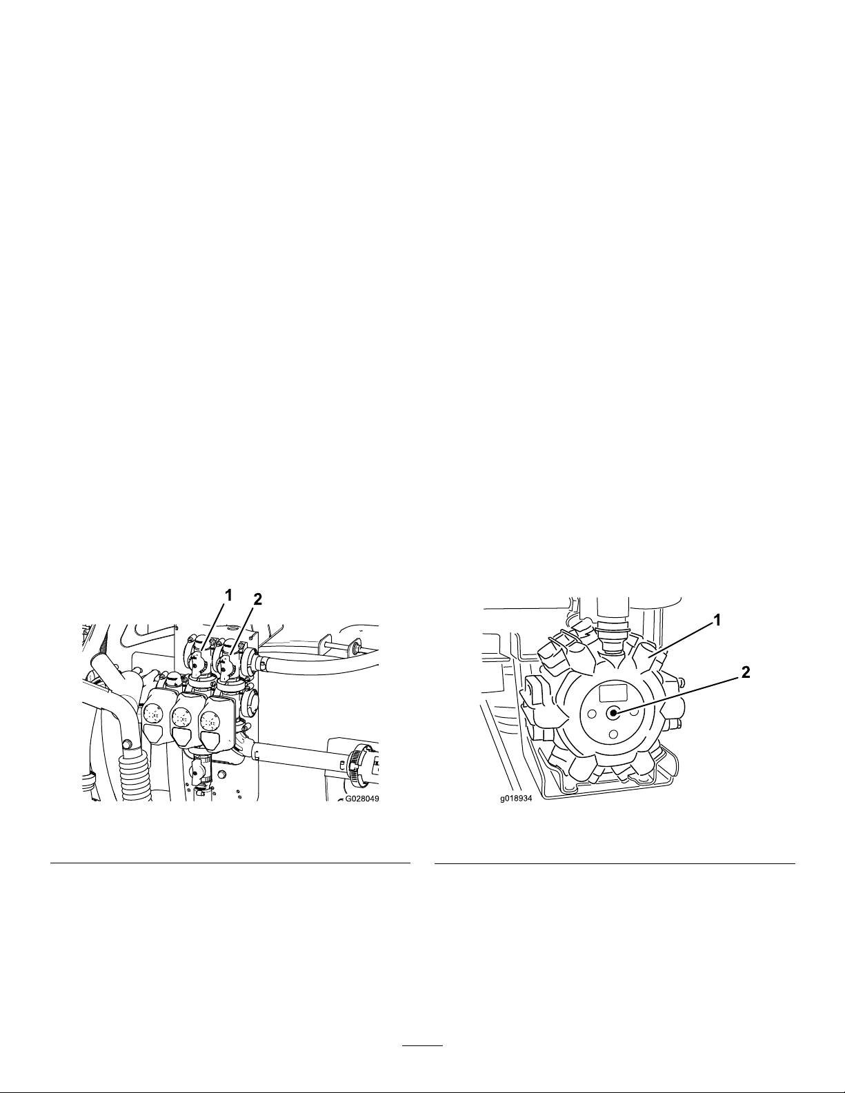
9.Adjustthemasterboombypasshandletocontrolthe
amountofagitationoccurringinthetank(Figure19).
10.Reducethethrottlespeedtoidle.
11.SettheagitationswitchandpumpswitchtotheOff
position.
12.Shutoffthemachine.
11.Adjusttheagitationbypassvalve(Figure19)onthe
backsideoftheagitationvalveuntilthepressure
readingonthegaugeis6.9bar(100psi).
Figure19
1.Agitationbypassvalve2.Masterboombypass
12.PressthepumpswitchtotheOffposition,shiftthe
throttlelevertotheIdleposition,andturntheignition
switchOff.
LocatingthePump
Thepumpislocatedundertheseat(Figure20).
Figure20
1.Pump
2.Greasetting
33
Page 34
TransportingtheSprayer
Formovingthesprayerlongdistances,useatrailer.Secure
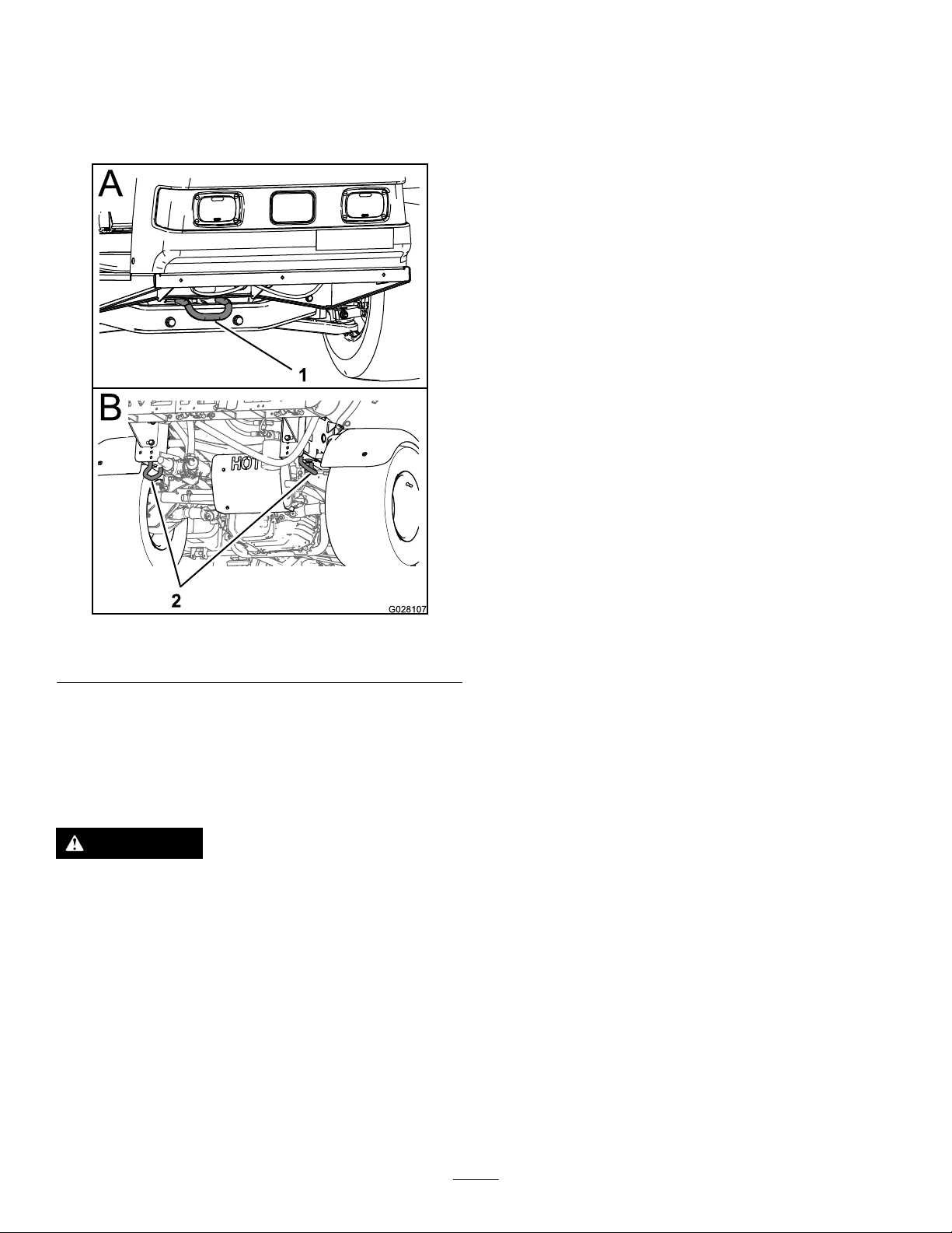
thesprayertothetrailer.Also,makesurethattheboomsare
tieddownandsecure.Thereis1metallooponthefrontof
theframeand2loopsontherearoftheframe(Figure21).
Figure21
1.Fronttie-downpoint2.Reartie-downpoints
TowingtheSprayer
Incaseofanemergency,thesprayercanbetowedforashort
distance.However,wedonotrecommendthisasastandard
procedure.
WARNING
Towingatexcessivespeedscouldcausealossof
steeringcontrol,resultinginpersonalinjury.
Nevertowthesprayerfasterthan8km/h(5mph).
Towingthesprayerisa2–personjob.Ifthemachinemust
bemovedaconsiderabledistance,transportitonatruckor
trailer;refertoTransportingtheSprayer(page34).
1.Attachatowlinetotheframe.
2.PuttherangeselectorintheNeutralpositionand
releasetheparkingbrake.
3.Towthesprayeratlessthan8km/h(5mph).
34
Page 35

Maintenance
Note:LookingforanElectricalSchematicorHydraulicSchematicforyourmachine?Downloadafreecopyoftheschematicby
visitingwww .Toro.comandsearchingforyourmachinefromtheManualslinkonthehomepage.
Foradditionalinformationaboutthesprayersystem,refertoFigure44inSprayerFlowDiagram(page51).
Note:Determinetheleftandrightsidesofthemachinefromthenormaloperatingposition.
RecommendedMaintenanceSchedule(s)
MaintenanceService
Interval
Aftertherst8hours
Aftertherst50hours
Beforeeachuseordaily
Every50hours
Every100hours
MaintenanceProcedure
•T orquethewheellugnuts.
•Replacethehydrauliclter.
•Changetheengineoil.
•Checktheenginerotatingscreen.
•Checktheengineoil.
•Checkthetirepressure.
•Cleanthesuctionstrainer(moreoftenwhenusingwetablepowders).
•Lubricatethepump.
•Cleanandoiltheaircleanerfoamelement(moreoftenindusty,dirtyconditions).
•Checkthebatterycableconnections.
•Checkthebatteryelectrolytelevel.
•Lubricateallgreasettings.
•Lubricatetheboomhinges.
•Cleantheenginerotatingscreen(moreoftenindusty,dirtyconditions).
•Changetheengineoil(moreoftenwhenoperatingunderheavyloadorinhigh
temperature).
•Replacetheengineoillter.
•Replacethefuellter.
•T orquethewheellugnuts.
•Inspecttheconditionandwearofthetires.
•Checkfrontwheeltoe-in.
•Inspectthebrakes.
•Replacetheaircleanerpaperelement(moreoftenindusty,dirtyconditions).
•Changethesparkplugs.
Every200hours
Every400hours
Every800hours
Yearly
•Checktheparkingbrake.
•Checkthetransaxle/hydraulicuid.
•Inspectallhosesandconnectionsfordamageandproperattachment.
•Cleantheowmeter(moreoftenwhenusingwettablepowders).
•Completeallyearlymaintenanceprocedurespeciedintheengineoperator's
manual.
•Inspectthefuellines.
•Drainandcleanthefueltank.
•Changethepressurelter.
•Inspectthepumpdiaphragmsandreplaceifnecessary(seeanAuthorizedT oro
ServiceDistributor).
•Inspectthepumpcheckvalvesandreplaceifnecessary(seeanAuthorizedToro
ServiceDistributor).
•Inspectthecenterboomnylonpivotbushings.
•Changethetransaxle/hydraulicuidandcleanstrainer.
•Replacethehydrauliclter.
•Calibratetheagitationbypassvalve.
Important:Refertoyourengineowner'smanualforadditionalmaintenanceprocedures.
35
Page 36
DailyMaintenanceChecklist
Duplicatethispageforroutineuse.
Checkthebrakeandparkingbrake
operation.
Checkthegearshift/neutraloperation.
Checkthefuellevel.
Checktheengineoillevel.
Checkthetransaxleoillevel.
Inspecttheairlter.
Inspecttheenginecoolingns.
Checkanyunusualenginenoises.
Checkanyunusualoperatingnoises.
Checkthetirepressure.
Checkforuidleaks.
Checktheinstrumentoperation.
Checktheacceleratoroperation.
Cleanthesuctionstrainer.
Checktoe-in.
Lubricateallgreasettings.
Touchupanddamagedpaint.
1
Fortheweekof: MaintenanceCheckItem
Mon.Tues.Wed.Thurs.Fri.
Sat.Sun.
1
Immediatelyaftereverywashing,regardlessoftheintervallisted
36
Page 37
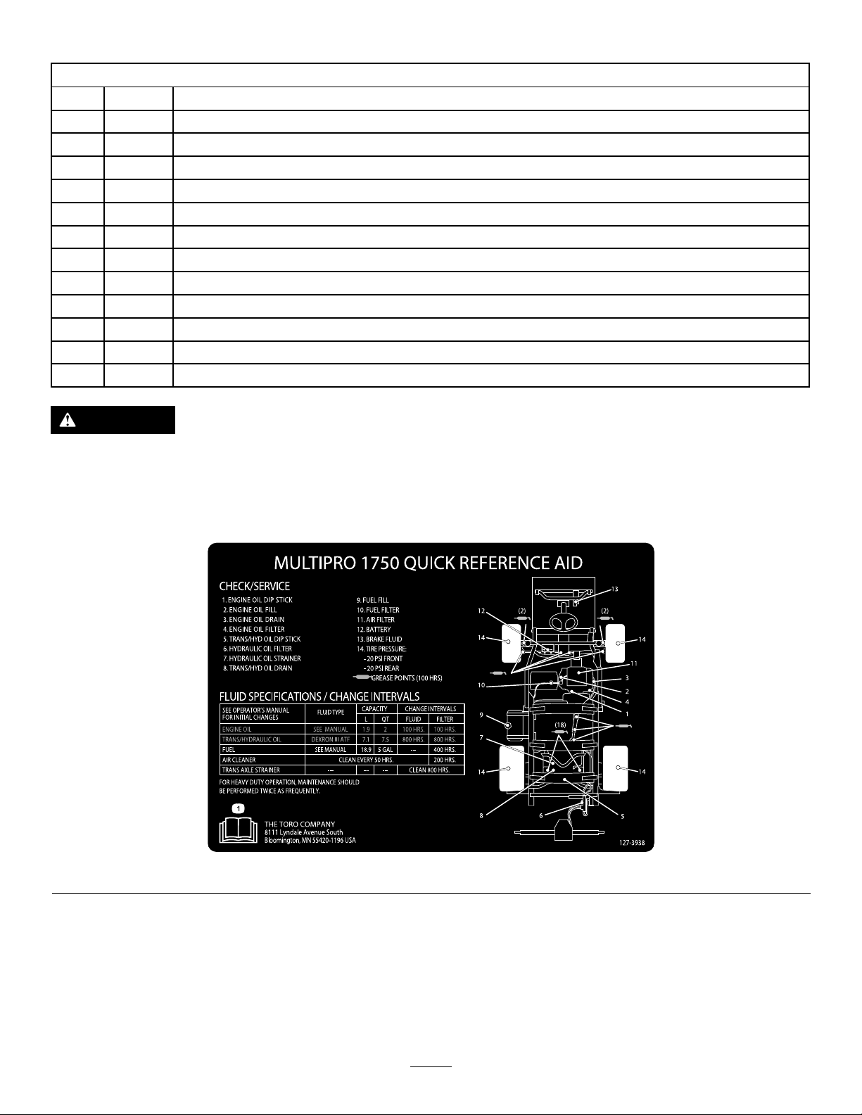
NotationforAreasofConcern
Inspectionperformedby:
ItemDate
1
2
3
4
5
6
7
8
9
10
11
12
CAUTION
Ifyouleavethekeyintheignitionswitch,someonecouldaccidentlystarttheengineandseriouslyinjure
youorotherbystanders.
Information
Removethekeyfromtheignitionanddisconnectthewire(s)fromthesparkplug(s)beforeyoudoany
maintenance.Setthewire(s)asidesothatitdoesnotaccidentallycontactthesparkplug(s).
Figure22
37
Page 38
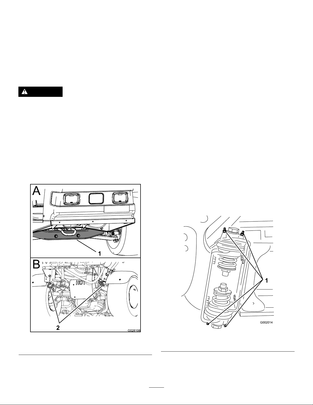
Premaintenance
Lubrication
Procedures
GreasingtheSprayer
JackingUptheSprayer
Whenevertheengineisrunforroutinemaintenanceand/or
enginediagnostics,therearwheelsofthesprayershouldbe
2.5cm(1inch)offofthegroundwiththerearaxlesupported
onjackstands.
DANGER
Asprayeronajackmaybeunstableandslipoffof
thejack,injuringanyonebeneathit.
•Donotstarttheenginewhilethesprayerisona
jack.
•Alwaysremovethekeyfromtheignitionbefore
gettingoffofthesprayer.
•Blockthetireswhenthesprayerisonajack.
Thejackingpointatthefrontofthesprayerisunderthefront
crossbar.Thejackingpointattherearofthesprayerisonthe
rearframesupport,behindthereartiedowns(Figure23).
ServiceInterval:Every50hours—Lubricatethepump.
Every100hours/Yearly(whichevercomes
rst)—Lubricateallgreasettings.
GreaseType:No.2general-purpose,lithium-basedgrease
1.Wipethegreasettingcleansothatforeignmatter
cannotbeforcedintothebearingorbushing.
2.Pumpgreaseintothebearingorbushing.
3.Wipeoffexcessgrease.
SeeFigure22forthelocationofallofthegreasepoints.
GreasingtheBoomHinges
ServiceInterval:Every100hours
Important:Iftheboomhingeiswashedwithwater,
allwateranddebrismustbeclearedfromthehinge
assemblyandfreshgreasemustbeapplied.
GreaseType:No.2general-purpose,lithium-basedgrease
1.Wipethegreasettingscleansothatforeignmatter
cannotbeforcedintothebearingorbushing.
Figure23
1.Frontjackingpoint2.Reartiedowns
2.Pumpgreaseintothebearingorbushingateachtting
Figure24.
Figure24
1.Greasetting
3.Wipeoffexcessgrease.
4.Repeattheprocedureforeachboompivot.
38
Page 39
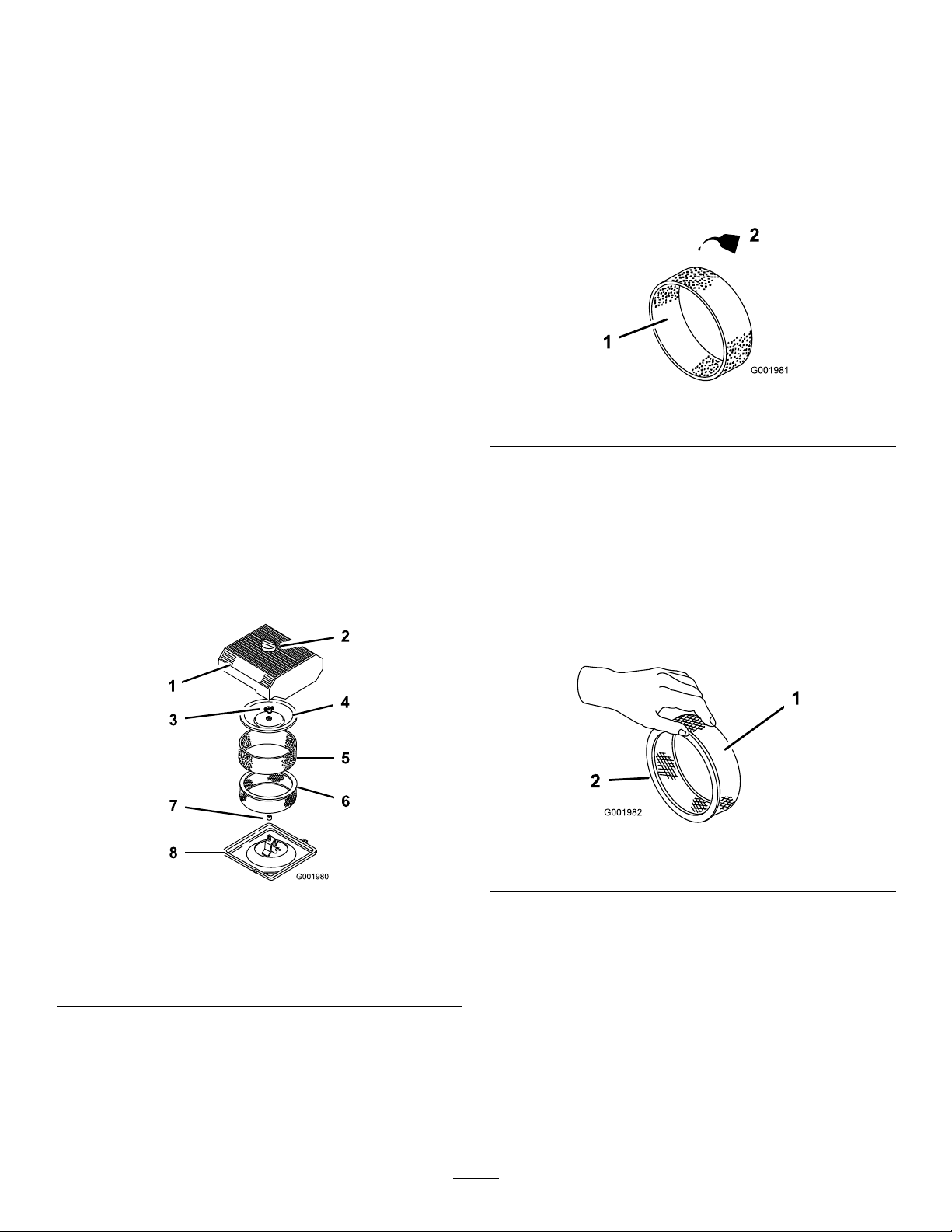
EngineMaintenance
CleaningtheFoamElement
1.Washthefoamelementinliquidsoapandwarmwater.
CheckingtheAirIntakeScreen
ServiceInterval:Beforeeachuseordaily—Checktheengine
rotatingscreen.
Every100hours—Cleantheenginerotatingscreen
(moreoftenindusty,dirtyconditions).
Checkandcleanasnecessarytheairintakescreenonthe
frontoftheenginebeforeeachuseordaily.
ServicingtheAirCleaner
ServiceInterval:Every50hours/Yearly(whichever
comesrst)(moreoftenindusty,dirty
conditions).
Every200hours/Y early(whichevercomesrst)(more
oftenindusty,dirtyconditions).
RemovingtheFoamandPaper
Elements
1.Settheparkingbrake,stopthepump,stoptheengine,
andremovetheignitionkey .
2.Releasethelatchonthebackoftheseatandliftthe
seatforward.
3.Cleanaroundtheaircleanertopreventdirtfrom
gettingintotheengineandcausingdamage(Figure25).
2.Whentheelementisclean,rinseitthoroughly.
3.Drytheelementbysqueezingitinacleancloth.
4.Put1or2ouncesofoilontheelement(Figure26).
Important:Replacethefoamelementifitistorn
orworn.
Figure26
1.Foamelement
5.Squeezetheelementtodistributetheoil.
2.Oil
CheckingthePaperElement
Inspectthepaperelementfortears,anoilylm,damageto
therubberseal,excessivedirt,orotherdamage(Figure27).If
anyoftheseconditionsexit,replacethelter.
Important:Donotcleanthepaperelementwith
pressurizedairorliquids,suchassolvent,gas,or
kerosene.
Figure25
1.Aircleanercover5.Foamelement
2.Knob6.Paperelement
3.Covernut
4.Cover
4.Loosentheknobontheaircleanercoverandremove
thecover(Figure25).
5.Carefullyslidethefoamelementoffthepaperelement
(Figure25).
6.Unscrewthecovernutandremovethecoverandpaper
element(Figure25).
7.Rubberseal
8.Aircleanerbase
Figure27
1.Paperelement2.Rubberseal
Important:T opreventenginedamage,alwaysoperate
theenginewiththecompletefoamandpaperaircleaner
assemblyinstalled.
InstallingtheFoamandPaperElements
1.Carefullyslidethefoamelementontothepaperair
cleanerelement(Figure25).
2.Slidetheaircleanerassemblyandcoverontothelong
rod.
3.Installthecovernutnger-tightagainstthecover
(Figure25).
39
Page 40
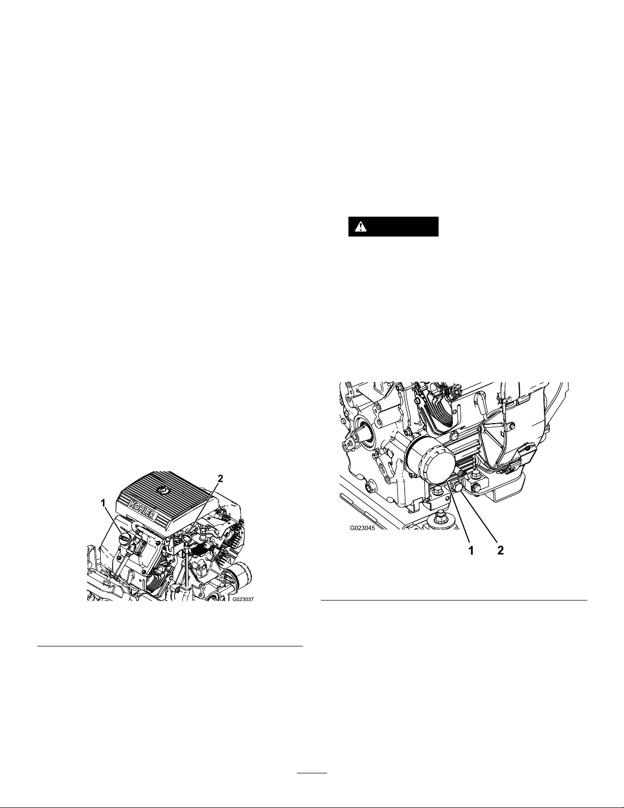
Note:Ensurethattherubbersealisatagainstthe
aircleanerbaseandcover.
4.Installtheaircleanercoverandknob(Figure25).
5.Closeandlatchtheseat.
ServicingtheEngineOil
CrankcaseCapacityis2.0L(2.1qt)withthelter.
ChangingtheEngineOil
ServiceInterval:Aftertherst50hours—Changethe
engineoil.
Every100hours—Changetheengineoil(more
oftenwhenoperatingunderheavyloadorinhigh
temperature).
1.Starttheengineandletitrunforveminutes.This
warmstheoilsoitdrainsbetter.
Usehigh-qualityengineoilthatmeetsthefollowing
specications:
•APIclassicationLevelrequired:SJ,JK,SL,orhigher.
•Preferredoil:SAE10W30(above0°F)
•Alternateoil:SAE5W30(below32°F)
ToroPremiumEngineOilisavailablefromyourdistributor
ineither10W30or5W30viscosity.SeethePartsCatalogfor
partnumbers.
CheckingtheEngineOil
ServiceInterval:Beforeeachuseordaily
Every400hours/Yearly(whichevercomesrst)
Theengineisshippedwithoilinthecrankcase;however,the
levelofoilmustbecheckedbeforeyourststarttheengine
andafteryouhaverunit.
1.Positionthemachineonalevelsurface.
2.Removethedipstickandwipeitwithacleanrag
(Figure28).Insertthedipstickintothetubeandmake
sureitisseatedfully.Removethedipstickandcheck
theoillevel.
2.Settheparkingbrake,stopthepump,stoptheengine,
andremovetheignitionkey .
3.Releasethelatchonthebackoftheseatandliftthe
seatforward.
CAUTION
Componentsundertheseatwillbehotifthe
sprayerhasbeenrunning.Ifyoutouchhot
componentsyoumaybeburned.
Allowthesprayertocoolbeforeperforming
maintenanceortouchingcomponentsunder
thehood.
4.Placeapanbelowtheoildrain.
5.Removethedrainplug(Figure29).
Figure28
1.Fillercap2.Dipstick
3.Iftheoillevelislow,removethellercapfromthe
valvecover(Figure28)andpouroilintotheopening
untiltheoillevelisuptotheFullmarkonthedipstick.
Addtheoilslowlyandchecktheleveloftenduringthis
process.Donotoverll.
4.Installthedipstickrmlyinplace.
Figure29
1.Oillter2.Oildrainplug
6.Whentheoilhasdrainedcompletely,replacethedrain
plugandtorqueitto13.6N-m(10ft-lb).
7.Disposeoftheusedoilatacertiedrecyclingcenter.
8.Slowlypourapproximately80%ofthespecied
amountofoilintotheoilllertube(Figure28).
9.Checktheoillevel.
10.Slowlyaddadditionaloiltobringtheoilleveltothe
fullmarkonthedipstick.
40
Page 41
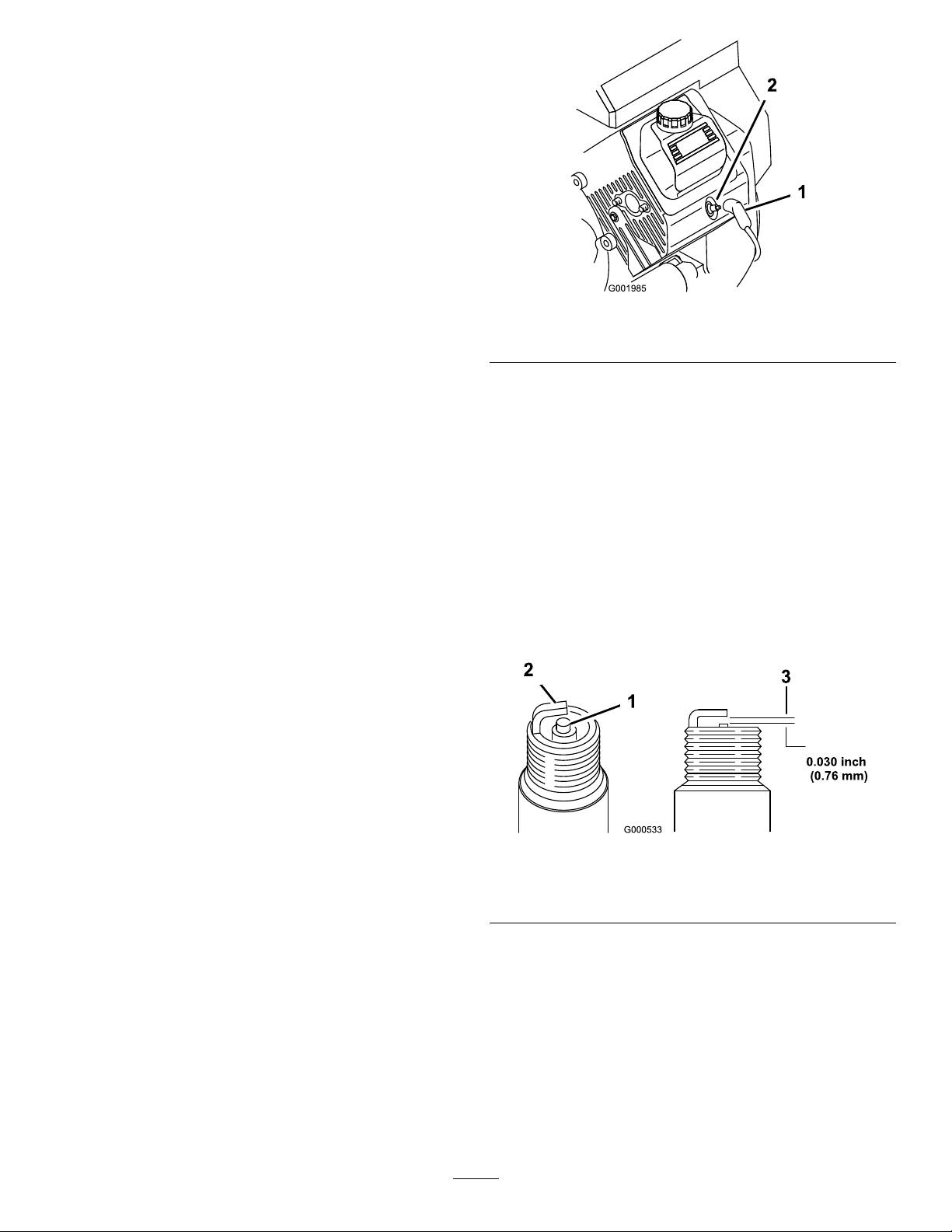
Important:Overllingthecrankcasewithoilmay
causeenginedamage.
ChangingtheEngineOilFilter
ServiceInterval:Every100hours
1.Draintheoilfromtheengine;refertoChangingthe
EngineOil(page40).
2.Removetheoillter(Figure29).
3.Wipethelteradaptergasketsurface.
4.Applyathincoatofnewoiltotherubbergasketon
thereplacementlter.
5.Installthereplacementoilltertothelteradapter.
Turntheoillterclockwiseuntiltherubbergasket
contactsthelteradapter,thentightenthelteran
additional1/2turn(Figure29).
6.Fillthecrankcasewiththecorrecttypeofnewoil;refer
toChangingtheEngineOil(page40),steps8through
10.
7.Disposeoftheusedoillteratacertiedrecycling
center.
Figure30
1.Sparkplugwire2.Sparkplug
CheckingtheSparkPlugs
1.Lookatthecenterofthesparkplugs(Figure31).
Ifyouseealightbrownorgraycoatingontheinsulator,
theengineisoperatingproperly .Ablackcoatingonthe
insulatorusuallymeanstheaircleanerisdirty.
ChangingtheSparkPlugs
ServiceInterval:Every200hours
Type:ChampionRC-12YC(orequivalent)
AirGap:0.76mm(0.030inch)
Makesurethattheairgapbetweenthecenterandside
electrodesiscorrectbeforeinstallingthesparkplugs.Usea
sparkplugwrenchforremovingandinstallingthesparkplugs
andagappingtool/feelergaugetocheckandadjusttheair
gap.
RemovingtheSparkPlug
1.Settheparkingbrake,stopthepump,stoptheengine,
andremovetheignitionkey .
2.Releasethelatchonthebackoftheseatandliftthe
seatforward.
3.Pullthewiresoffthesparkplugs(Figure30).
4.Cleanaroundthesparkplugstopreventdirtfrom
fallingintotheengineandpotentiallycausingdamage.
5.Removethesparkplugsandmetalwashers.
Important:Donotcleanthesparkplugs.Always
replaceasparkplugwhenithasablackcoating,
wornelectrodes,anoilylm,orcracks.
2.Checkthegapbetweenthecenterandsideelectrodes
(Figure31)andbendthesideelectrode,ifthegapis
notcorrect.
Figure31
1.Centerelectrodeinsulator3.Airgap(nottoscale)
2.Sideelectrode
InstallingtheSparkPlugs
1.Installthesparkplugsandmetalwashers.
2.Tightenthesparkplugsto24.4to29.8N-m(18to22
ft-lb).
3.Pushthewiresontothesparkplugs(Figure30).
4.Closeandlatchtheseat.
41
Page 42
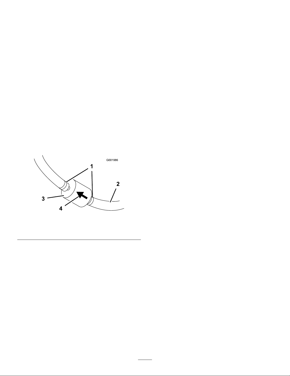
FuelSystem
Maintenance
ReplacingtheFuelFilter
ServiceInterval:Every100hours—Replacethefuellter.
Every400hours/Yearly(whichevercomes
rst)—Inspectthefuellines.
1.Settheparkingbrake,stopthepump,stoptheengine,
andremovetheignitionkey .
2.Releasethelatchonthebackoftheseatandliftthe
seatforward.
3.Clampoffthehoseoneithersideofthefuellterto
preventgasfrompouringoutofthehoseswhenyou
removethelter.
4.Placeadrainpanunderthelter.
5.Squeezetheendsofthehoseclampstogetherandslide
themawayfromthelter(Figure32).
6.Removethelterfromthefuellines.
DrainingtheFuelTank
ServiceInterval:Every400hours/Yearly(whichevercomes
rst)
Drainandcleanthefueltankifthefuelsystembecomes
contaminatedorifyouplantostorethemachineforan
extendedperiod.Usefresh,cleanfueltoushoutthetank.
1.Transferthefuelfromthetankintoanapprovedfuel
containerusingasiphonpump,orremovethetank
fromthemachineandpourthefueloutofthetankll
spoutintothefuelcontainer.
Note:Ifyouremovethefueltank,youwillneedto
removethefuelandreturnhosesfromthetankbefore
removingthetank.
2.Replacethefuellter;refertoReplacingtheFuelFilter
(page42).
3.Flushthetankwithfresh,cleanfuel,ifnecessary.
4.Installthetankifyouremovedit.
5.Fillthetankwithfresh,cleanfuel.
Figure32
1.Hoseclamp3.Filter
2.Fuelline4.Flowdirectionarrow
7.Installanewlterandmovethehoseclampscloseto
thelter.
Ensurethattheowdirectionarrowpointstoward
theengine.
42
Page 43
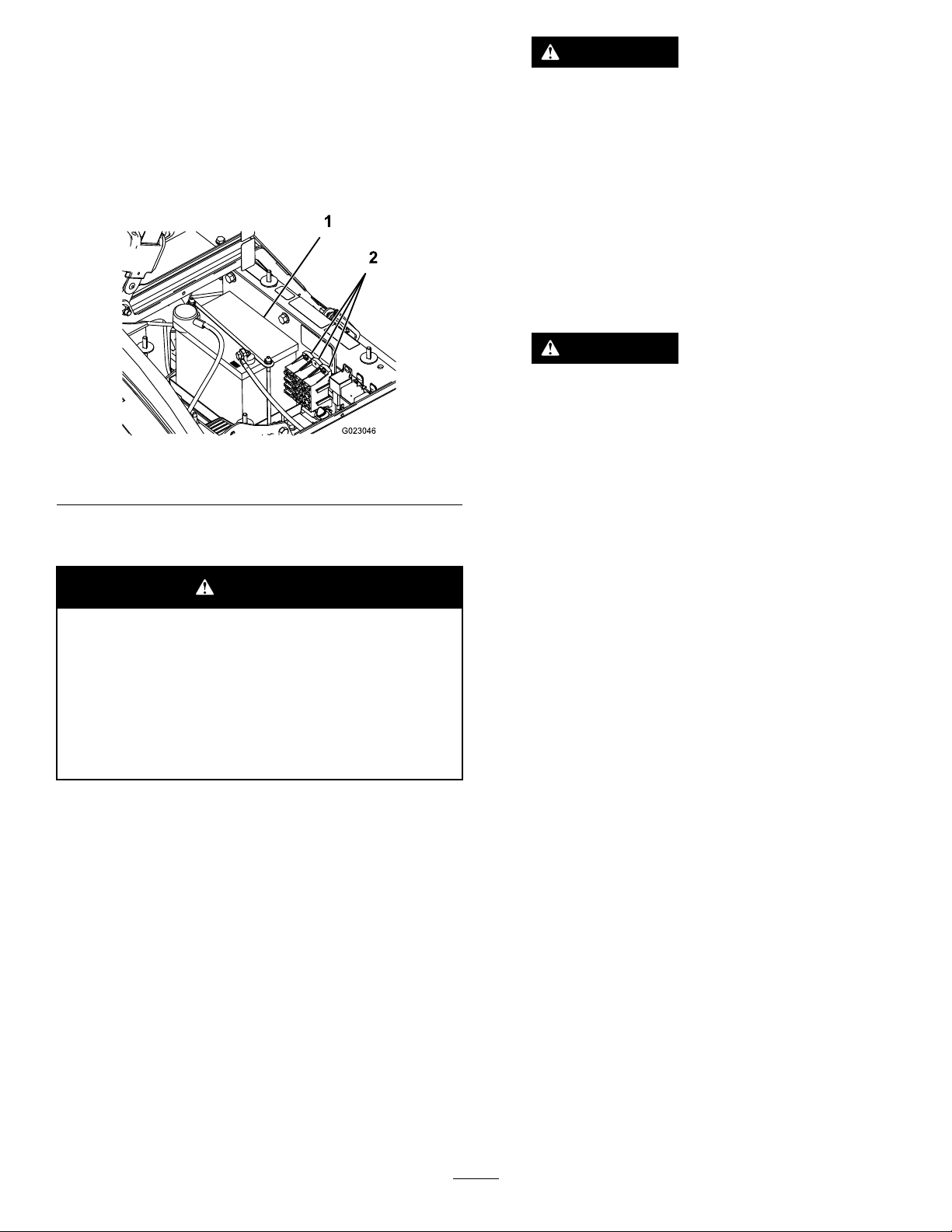
ElectricalSystem
Maintenance
LocatingtheFuses
WARNING
Incorrectbatterycableroutingcoulddamage
thesprayerandcablescausingsparks.Sparks
cancausethebatterygassestoexplode,
resultinginpersonalinjury.
Thereare2fuseblocksand1emptyslotintheelectrical
system.Theyarelocatedbeneaththeseat(Figure33).
Figure33
1.Battery2.Fuseblocks
ServicingtheBattery
WARNING
CALIFORNIA
Proposition65Warning
Batteryposts,terminals,andrelated
accessoriescontainleadandleadcompounds,
chemicalsknowntotheStateofCalifornia
tocausecancerandreproductiveharm.
Washhandsafterhandling.
•Alwaysdisconnectthenegative(black)
batterycablebeforedisconnectingthe
positive(red)cable.
•Alwaysreconnectthepositive(red)battery
cablebeforereconnectingthenegative
(black)cable.
WARNING
Batteryterminalsormetaltoolscouldshort
againstmetalsprayercomponentscausing
sparks.Sparkscancausethebatterygassesto
explode,resultinginpersonalinjury.
•Whenremovingorinstallingthebattery,
donotallowthebatteryterminalstotouch
anymetalpartsofthesprayer.
•Donotallowmetaltoolstoshortbetween
thebatteryterminalsandmetalpartsof
thesprayer.
•Alwayskeepthebatterystrapinplaceto
protectandsecurethebattery.
4.Disconnectthepositive(red)cablefromthebattery
post.
5.Removethebatteryretainerandfasteners(Figure33).
6.Removethebattery.
Important:Donotjumpstartthesprayer.
Alwayskeepthebatterycleanandfullycharged.Useapaper
toweltocleanthebatteryandbatterybox.Ifthebattery
terminalsarecorroded,cleanthemwithasolutionoffour
partswaterandonepartbakingsoda.Applyalightcoatingof
greasetothebatteryterminalstopreventcorrosion.
Voltage:12voltwith280coldcrankingAmpsat0°F
RemovingtheBattery
1.Positionthesprayeronalevelsurface,settheparking
brake,stopthepump,stoptheengine,andremovethe
ignitionkey .
2.Thebatteryislocatedontherighthandsideofthe
machinebehindthepump(Figure33).
3.Disconnectthenegative(black)groundcablefromthe
batterypost.
InstallingtheBattery
ServiceInterval:Every50hours—Checkthebatterycable
connections.
1.Setthebatteryonthebatteryboxsothatthebattery
postsaretowardthefrontofthesprayer.
2.Installthebatteryretainerandsecureitwiththe
fastenersyouremovedpreviously(Figure33).
Important:Alwayskeepthebatteryretainerin
placetoprotectandsecurethebattery.
3.Connectthepositive(red)cabletothepositive(+)
batterypostandthenegative(black)cabletothe
negative(-)batterypostusingtheboltsandwingnuts.
Slidetherubberbootoverthepositivebatterypost.
4.Installthebatterycoverandsecureitwiththe2knobs
(Figure33).
43
Page 44

CheckingtheElectrolyteLevel
ServiceInterval:Every50hours
Note:Whenthemachineisinstoragecheckthebattery
electrolytelevelevery30days.
1.Loosentheknobsonthesidesofthebatteryboxand
removethebatterycover(Figure33).
3.Connecta3to4ampbatterychargertothebattery
posts.Chargethebatteryatarateof3to4amperes
for4to8hours(12volts).
Important:Donotoverchargethebattery.
4.Installthebatteryinthechassis;refertoInstallingthe
Battery(page43).
2.Removethellercaps.Iftheelectrolyteisnotupto
thellline,addtherequiredamountofdistilledwater;
refertoAddingWatertotheBattery(page44).
DANGER
Batteryelectrolytecontainssulfuricacid
whichisadeadlypoisonandcausessevere
burns.
•Donotdrinkelectrolyteorallowitto
contactyourskin,eyesorclothing .Wear
safetyglassestoshieldyoureyesand
rubberglovestoprotectyourhands.
•Fillthebatterywherecleanwaterisalways
availableforushingtheskin.
AddingWatertotheBattery
Thebesttimetoadddistilledwatertothebatteryisjust
beforeyouoperatethemachine.Thisletsthewatermix
thoroughlywiththeelectrolytesolution.
1.Cleanthetopofthebatterywithapapertowel.
StoringtheBattery
Ifthemachinewillbestoredformorethan30days,remove
thebatteryandchargeitfully .Eitherstoreitontheshelforon
themachine.Leavethecablesdisconnectedifitisstoredon
themachine.Storethebatteryinacoolatmospheretoavoid
quickdeteriorationofthechargeinthebattery.Toprevent
thebatteryfromfreezing,makesureitisfullycharged.
2.Removethellercapsfromthebatteryandslowlyll
eachcellwithdistilledwateruntilthelevelisuptothe
llline.Replacethellercaps.
Important:Donotoverllthebattery.Electrolyte
willoverowontootherpartsofthesprayerand
severecorrosionanddeteriorationwillresult.
ChargingtheBattery
WARNING
Chargingthebatteryproducesgassesthatcan
explode.
Neversmokenearthebatteryandkeepsparksand
amesawayfrombattery.
Important:Alwayskeepthebatteryfullycharged(1.260
specicgravity).Thisisespeciallyimportanttoprevent
batterydamagewhenthetemperatureisbelow0°C(32°
F).
1.Removethebatteryfromthechassis;refertoRemoving
theBattery(page43).
2.Checktheelectrolytelevel;refertoCheckingthe
ElectrolyteLevel(page44).
44
Page 45
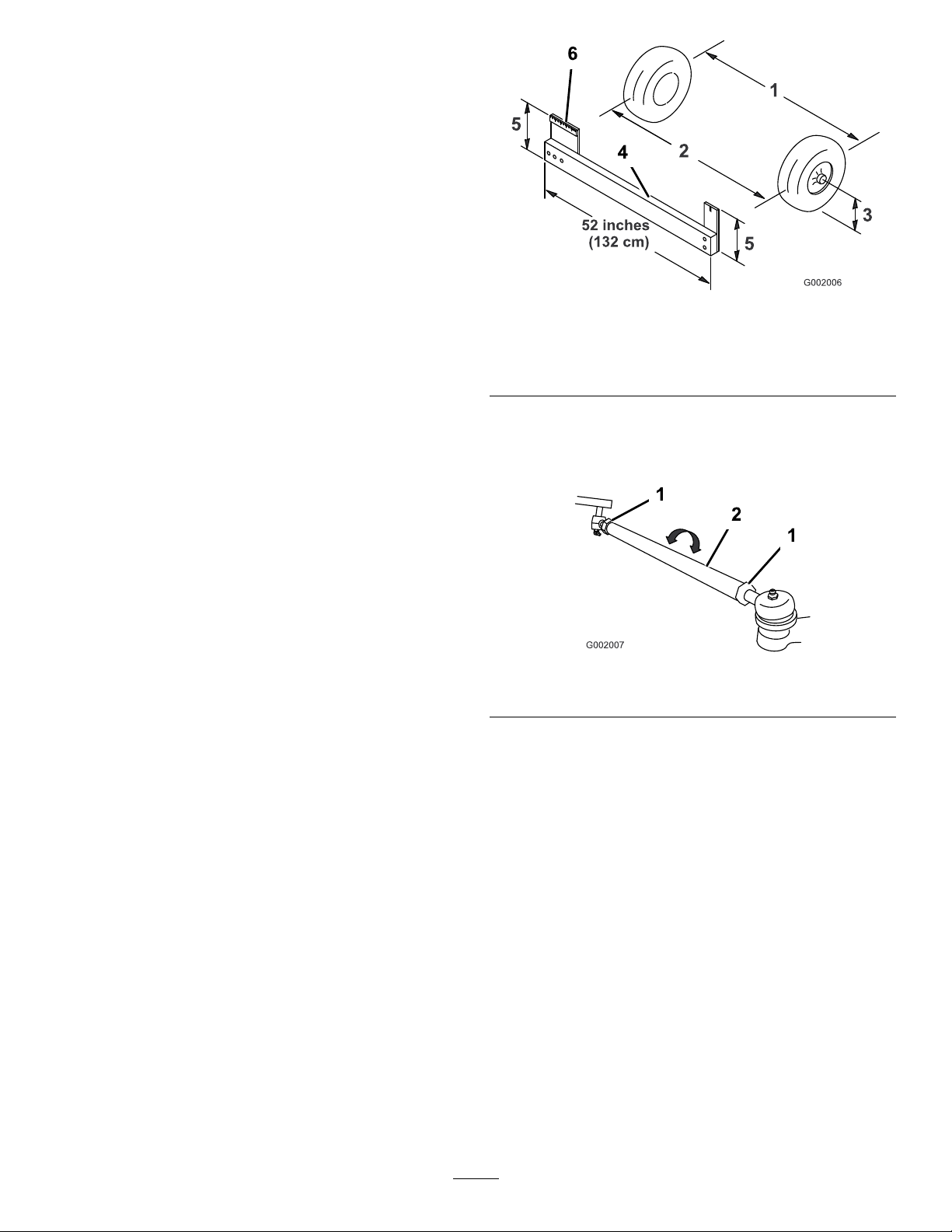
DriveSystem
Maintenance
InspectingtheWheelsand Tires
ServiceInterval:Beforeeachuseordaily—Checkthetire
pressure.
Aftertherst8hours—Torquethewheellugnuts.
Every100hours—Torquethewheellugnuts.
Every100hours—Inspecttheconditionandwearof
thetires.
Checkthetirepressureevery8hoursordailytoensure
properlevels.Fillthetiresto138kPa(20psi).Also,check
thetiresforwearordamage.
Checkthewheelstoensurethattheyaremountedsecurely
aftertherst8operatinghoursandthenevery100hours
thereafter.Torquethefrontandrearlugnutsto102-108N-m
(75-80ft-lb).
Checkthetireconditionatleastevery100hoursofoperation.
Operatingaccidents,suchashittingcurbs,candamageatire
orrimandalsodisruptwheelalignment,soinspectthetire
conditionafteranaccident.
AdjustingtheFrontWheel Toe-in
ServiceInterval:Every100hours/Yearly(whichevercomes
rst)
Figure34
1.Tirecenterline-back4.Fixture
2.Tirecenterline-front
3.Axlecenterline
5.Ifthemeasurementdoesnotfallwithinthespecied
range,loosenthejamnutsatbothendsofthetierods
(Figure35).
1.Jamnut2.Tierod
5.Axlecenterlinedistance
6.15cm(6inches)ruler
Figure35
Thetoe-inshouldbe0to6mm(0to1/4inch).
1.Fillthetankwithapproximately331L(87.5USgallons)
ofwater.
2.Checkandllalltires;refertoCheckingtheTire
Pressure(page22).
3.Drivethesprayerbackandforthafewtimestorelax
theA-arms,thendriveitforwardatleast3m(10ft).
4.Measurethedistancebetweenbothofthefronttiresat
theaxleheightatboththefrontandrearofthefront
tires(Figure34).
Note:Axtureoralignmentgaugeisneededfor
therearmeasurementofthefronttiresataxleheight.
Usethesamextureoralignmentgaugetoaccurately
measurethefrontofthefronttiresataxleheight
(Figure34).
Thefrontofthetiresshouldbe0to6mm(0to1/4
inch)closerthanthebacksideofthefronttires.
6.Rotatebothtierodstomovethefrontofthetire
inwardoroutward.
Note:Thetierodsshouldbethesamelengthwhen
youarenished.
7.Tightenthetierodjamnutswhentheadjustmentis
correct.
8.Ensurethatthereisfulltravelofthesteeringwheelin
bothdirections.
45
Page 46
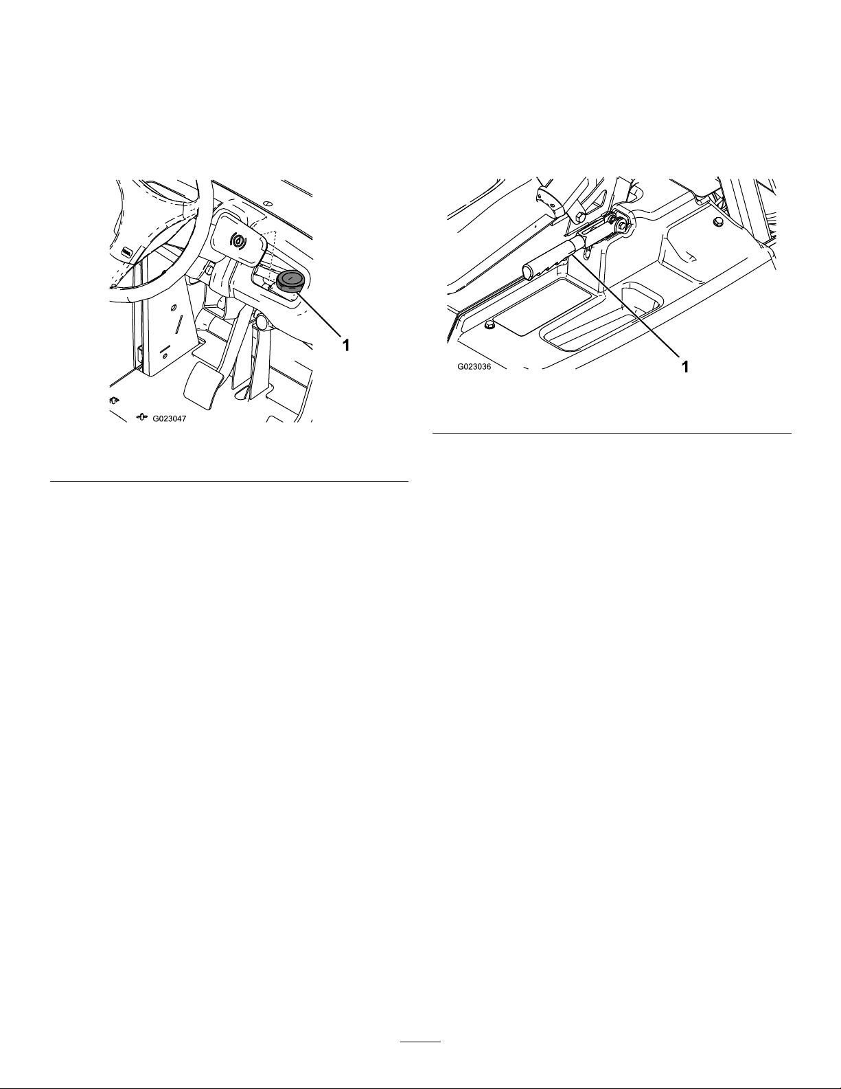
BrakeMaintenance
CheckingtheBrakeFluid
Thebrakeuidreservoirisshippedfromthefactorylled
withDOT3brakeuid.Checkthelevelbeforestartingthe
engineeachday.
Figure36
1.Brakeuidreservoir
AdjustingtheParkingBrake
ServiceInterval:Every200hours—Checktheparking
brake.
1.Removetheplasticgrip.
2.Loosenthesetscrewsecuringtheknobtotheparking
brakelever(Figure37).
Figure37
1.Parkingbrakelever
3.Rotatetheknobuntilaforceof18-23kg(40-50lb)is
requiredtoactuatelever.
1.Positionthesprayeronalevelsurface,settheparking
brake,stopthepump,stoptheengine,andremovethe
ignitionkey .
2.TheuidlevelshouldbeuptotheFulllineonthe
reservoir.
3.Iftheuidlevelislow,cleantheareaaroundthe
reservoircap,removethecap,andllthereservoirto
theproperlevel.Donotoverll.
InspectingtheBrakes
ServiceInterval:Every100hours
Thebrakesareacriticalsafetycomponentofthesprayer.
Inspectthemasfollows:
•Inspectthebrakeshoesforwearordamage.Ifthelining
(brakepad)thicknessislessthan1.6mm(1/16inch),
replacethebrakeshoes.
•Inspectthebackingplateandothercomponentsforsigns
ofexcessivewearordeformation.Ifanydeformationis
found,replacetheappropriatecomponents.
4.Tightenthesetscrew.
46
Page 47
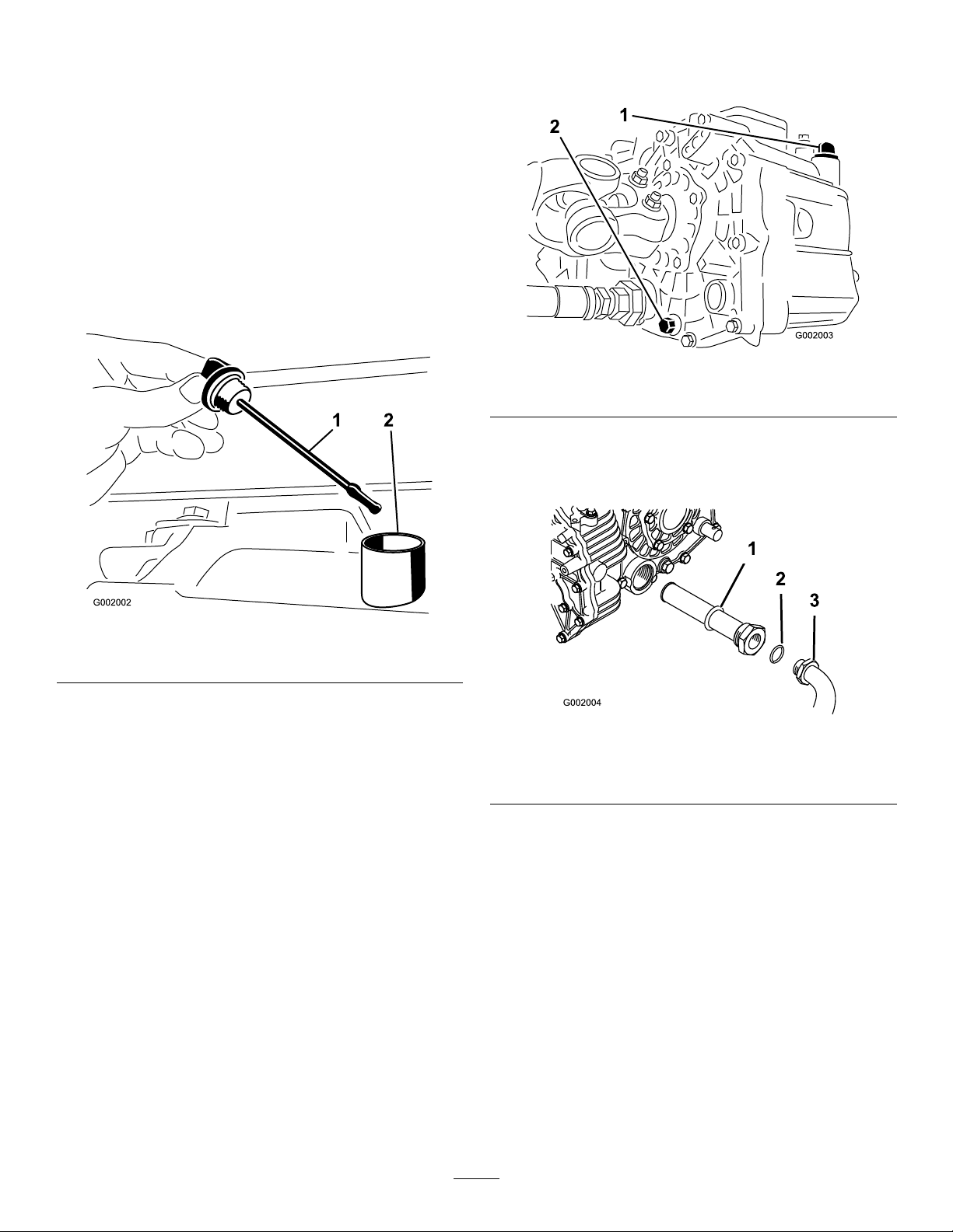
HydraulicSystem
Maintenance
Checkingthe Transaxle/HydraulicFluid
ServiceInterval:Every200hours
1.Positionthesprayeronalevelsurface,settheparking
brake,stopthepump,stoptheengine,andremovethe
ignitionkey .
2.Removethetransaxledipstickandwipeitwithaclean
rag(Figure38).
3.Removethedrainplugfromthesideofthereservoir,
andletthehydraulicuidowintothedrainpan
(Figure39).
Figure39
1.Hydraulicdipstick2.Drainplug
4.Notetheorientationofthehydraulichoseand90°
ttingconnectedtothestrainer.
5.Removethehydraulichoseand90°tting(Figure40).
Figure38
1.Dipstick2.Fillhole
Important:Beverycarefulnottogetdirtorother
contaminantsintotheopeningwhencheckingthe
transmissionoil.
3.Insertthedipstickintothetubeandmakesurethatit
isseatedfully.Removethedipstickandchecktheoil
level.
4.Thetransaxleuidlevelshouldbeatthetopof
theatportionofthedipstick.Ifitisnot,llthe
reservoirwiththeappropriateuid;refertoChanging
Transaxle/HydraulicFluid(page47).
5.Installthedipstickrmlyinplace.
ChangingTransaxle/Hydraulic Fluid
ServiceInterval:Every800hours/Yearly(whichevercomes
rst)
1.Positionthesprayeronalevelsurface,settheparking
brake,stopthepump,stoptheengine,andremovethe
ignitionkey .
2.Placeadrainpanunderthedrainplugofthereservoir.
Figure40
1.Hydraulicstrainer
2.O-ring
6.Removethestrainerandcleanitbybackushingit
withacleandegreaser.
7.Allowthestrainertoairdry.
8.Installthestrainerwhentheoilisdraining.
9.Installthehydraulichoseand90°ttingtothestrainer.
10.Installandtightenthedrainplug.
11.Fillthereservoirwithapproximately7L(7.5qt)of
DexronIIlATF.
Important:Useonlythehydraulicuids
specied.Otheruidscouldcausesystem
damage.
12.Starttheengineanddrivethesprayertollthe
hydraulicsystem.
13.Checktheoillevelandreplenishit,ifrequired.
3.90°tting
47
Page 48
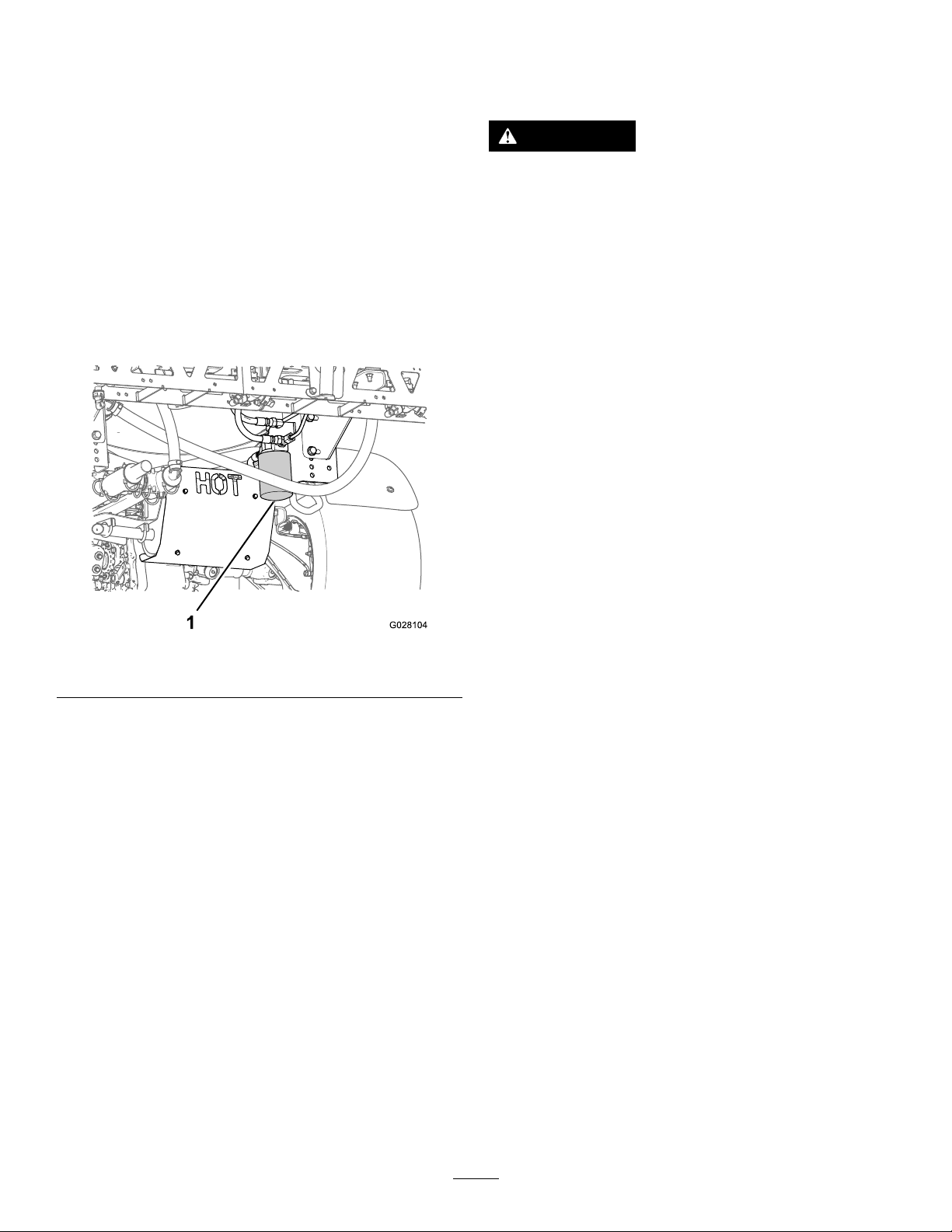
ReplacingtheHydraulicFilter
ServiceInterval:Aftertherst8hours
Every800hours/Yearly(whichevercomesrst)
SpraySystem Maintenance
UsetheTororeplacementlter(PartNo.54-0110).
Important:Useofanyotherltermayvoidthewarranty
onsomecomponents.
1.Positionthesprayeronalevelsurface,settheparking
brake,stopthepump,stoptheengine,andremovethe
ignitionkey .
2.Cleantheareaaroundtheltermountingarea.
3.Placeadrainpanunderthelter.
4.Removethelter(Figure41).
Figure41
1.Hydrauliclter
5.Lubricatethenewltergasket.
WARNING
Chemical substances used in the spray system may
be hazardous and to xic to y ou, bystander s, animals,
plants, soils or other pr oper ty .
•Carefullyreadandfollowthechemical
warninglabelsandMaterialSafetyData
Sheets(MSDS)forallchemicalsusedand
protectyourselfaccordingtothechemical
manufacturer'srecommendations.Forexample,
useappropriatePersonalProtectiveEquipment
(PPE),includingfaceandeyeprotection,gloves,
orotherequipmenttoguardagainstpersonal
contactwithchemicals.
•Keepinmindthattheremaybemorethanone
chemicalusedandinformationoneachshould
beassessed.
R efuse to operate or w or k on the spray er if this
•
inf or mation is not a v aila ble!
•Beforeworkingonaspraysystemmakesure
thatthesystemhasbeentriplerinsedand
neutralizedaccordingtotherecommendations
ofthechemicalmanufacturer(s)andallofthe
valveshavebeencycled3times.
•Verifythatthereisanadequatesupplyofclean
waterandsoapnearby,andimmediatelywash
offanychemicalsthatcontactyou.
6.Ensurethattheltermountingareaisclean.
7.Screwthelteronuntilthegasketcontactsthe
mountingplate,thentightenthelterone-halfturn.
8.Starttheengineandletitrunforabout2minutesto
purgeairfromthesystem.
9.Stoptheengineandcheckthehydraulicoilleveland
forleaks.
InspectingtheHoses
ServiceInterval:Every200hours—Inspectallhosesand
connectionsfordamageandproper
attachment.
Examineeachhoseinthespraysystemforcracks,leaksor
otherdamage.Atthesametime,inspecttheconnectionsand
ttingsforsimilardamage.Replaceanyhosesandttingsif
damaged.
48
Page 49
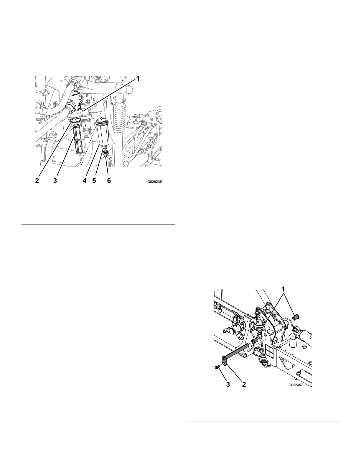
ChangingthePressureFilter
G022367
1
23
InspectingthePump
ServiceInterval:Every400hours
1.Movethemachinetoalevelsurface,shutoffthe
sprayerpump,shutofftheengine,andremovethekey
fromthestarterswitch.
2.Alignadrainpanunderthepressurelter(Figure42).
Figure42
1.Filterhead4.Bowl
2.O-ring(bowl)5.O-ring(drainplug)
3.Filterelement6.Drainplug
3.Rotatethedrainplugcounterclockwiseandremoveit
fromthebowlofthepressurelter(Figure42).
Note:Allowthebowltodraincompletely.
4.Rotatethebowlcounterclockwiseandremoveitlter
head(Figure42).
5.Removetheoldpressurelterelement(Figure42).
ServiceInterval:Every400hours/Yearly(whichevercomes
rst)—Inspectthepumpdiaphragmsand
replaceifnecessary(seeanAuthorized
ToroServiceDistributor).
Every400hours/Yearly(whichevercomes
rst)—Inspectthepumpcheckvalvesandreplace
ifnecessary(seeanAuthorizedToroService
Distributor).
Note:Thefollowingmachinecomponentsareconsidered
partssubjecttoconsumptionthroughuseunlessfound
defectiveandarenotcoveredbythewarrantyassociatedwith
thismachine.
HaveanAuthorizedToroServiceDistributorcheckfollowing
internalpumpcomponentsfordamage:
•Pumpdiaphragms
•Pumpcheckvalvesassemblies
Replaceanycomponents,ifnecessary.
InspectingtheNylonPivot Bushings
ServiceInterval:Every400hours/Yearly(whichevercomes
rst)
1.Positionthesprayeronalevelsurface,settheparking
brake,stopthepump,stoptheengine,andremovethe
ignitionkey .
2.Extendtheboomstothespraypositionandsupport
theboomsusingstandsorstrapsfromalift.
3.Withtheweightoftheboomsupported,remove
theboltandnutsecuringthepivotpintotheboom
assembly(Figure43).
Note:Discardtheoldlter.
6.ChecktheO-ringforthedrainplug(locatedinsidethe
bowl)andtheO-ringforbowl(locatedinsidethelter
head)fordamageandwear(Figure42).
Note:ReplaceanydamagedorwornO-ringsforthe
plug,bowl,orboth.
7.Installthenewpressurelterelementintothelter
head(Figure42).
Note:Ensurethatthelterelementisrmlyseated
intothelterhead.
8.Installthebowlontothelterheadhandtight(Figure
42).
9.Installtheplugintothebowlhandtight(Figure42).
Figure43
1.Nylonbushing3.Bolt
2.Pivotpin
4.Removethepivotpin.
49
Page 50

5.Removetheboomandpivotbracketassemblyfrom
thecenterframetoaccessthenylonbushings.
6.Removeandinspectthenylonbushingsfromthefront
andbacksidesofthepivotbracket(Figure43).
Note:Replaceanydamagedbushings.
7.Placeasmallamountofoilonthenylonbushingsand
installthemintopivotbracket.
8.Installtheboomandpivotbracketassemblyintothe
centerframe,aligningtheopenings(Figure43).
9.Installthepivotpinandsecureitwiththeboltandnut
removedpreviously.
10.Repeattheprocedureforeachboom.
50
Page 51
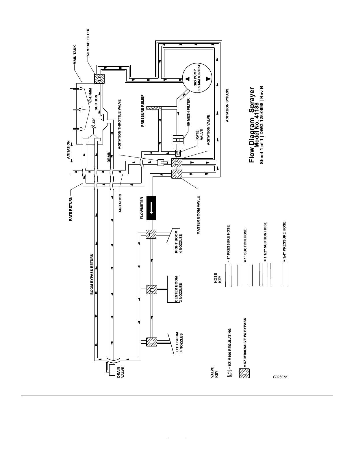
SprayerFlowDiagram
Figure44
51
Page 52
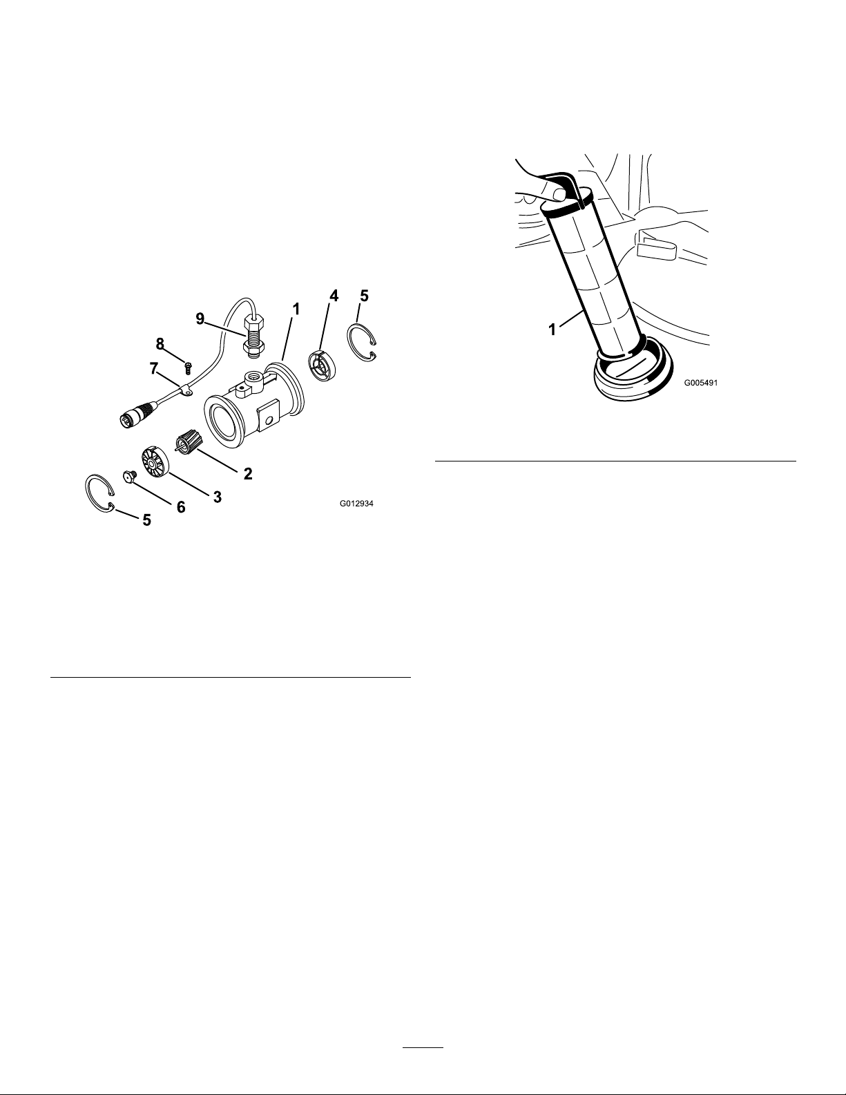
Cleaning
G012934
8
7
9
1
4 5
2
3
6
5
CleaningtheFlowmeter
ServiceInterval:Every200hours/Yearly(whichevercomes
rst)(moreoftenwhenusingwettable
powders).
1.Thoroughlyrinseanddraintheentiresprayingsystem.
2.Removetheowmeterfromthesprayer,andushit
withcleanwater.
3.Removetheretainerringontheupstreamside(Figure
45).
CleaningtheSuctionStrainer
ServiceInterval:Beforeeachuseordaily(moreoftenwhen
usingwetablepowders).
1.Removetheretainerfromtheredttingattachedto
thelargehoseonthetopofthetank.
Figure46
1.Suctionstrainer
Figure45
1.Modiedangedbody
2.Rotor/magnetassembly7.Cableclamp
3.Hub/bearingassembly
4.Hubassembly(with
keywayup)
5.Retainingring
4.Cleantheturbineandtheturbinehubtoremovemetal
lingsandanywettablepowders.
5.Inspecttheturbinebladesforwear.
Note:Holdtheturbineinyourhandandspinit.It
shouldspinfreelywithverylittledrag.Ifitdoesnot,
replaceit.
6.Assembletheowmeter.
7.Usealow-pressureairjet(50kPaor5psi)toensure
thattheturbinespinsfreely .Ifitdoesnot,loosenthe
hexstudonthebottomoftheturbinehubby1/16of
aturnuntiltheturbinespinsfreely.
6.Turbinestudassembly
8.Threadscrew
9.Sensorassembly
2.Disconnectthehosefromthetank.
3.Pullthestraineroutofthehole.
4.Cleanthestrainerwithcleanrunningwater.
5.Replacethestrainer,seatingitfullyintothehole.
6.Connectthehosetothetopofthetankandsecure
itwiththeretainer.
52
Page 53
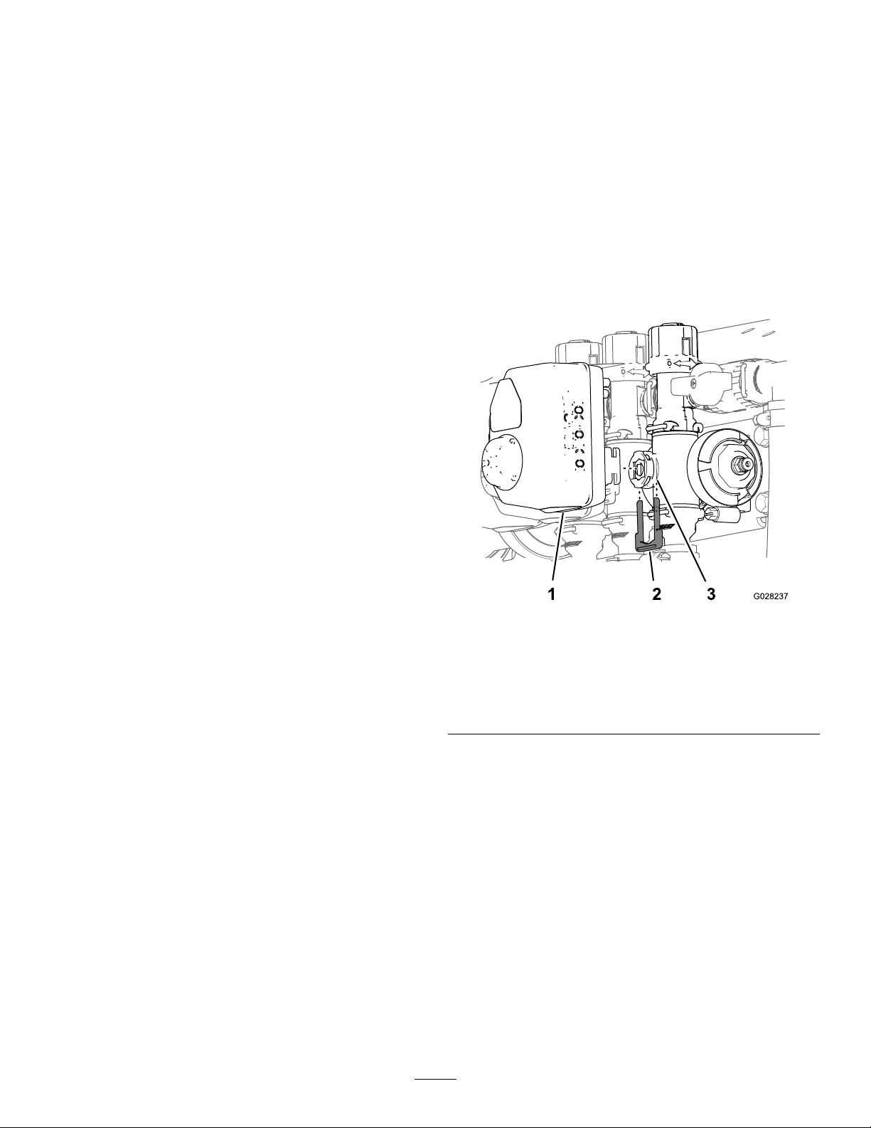
CleaningtheSprayerValves
•Tocleantheratecontrolvalve,refertothefollowing
sections:
1.RemovingtheValveActuator(page53)
2.RemovingtheRateControlManifoldValve(page
54)
3.CleaningtheManifoldValve(page57)
4.AssemblingtheManifoldValve(page58)
RemovingtheValveActuator
1.Positionthesprayeronalevelsurface,settheparking
brake,stopthepump,stoptheengine,andremovethe
keyfromthestarterswitch.
2.Removethe3-pinconnectorofthevalveactuatorfrom
the3socketelectricalconnectorofthesprayerharness.
3.Removetheretainerthatsecurestheaactuatortothe
manifoldvalvefortheratecontrol,agitation,master
boom,orboomsectionvalve(Figure47).
5.InstallingtheRateControlManifoldValve(page
59)
6.InstallingtheValveActuator(page62)
•Tocleantheagitationvalve;refertothefollowing
sections:
1.RemovingtheValveActuator(page53)
2.RemovingtheAgitationManifoldValve(page54)
3.CleaningtheManifoldValve(page57)
4.AssemblingtheManifoldValve(page58)
5.InstallingtheAgitationManifoldValve(page60)
6.InstallingtheValveActuator(page62)
•Tocleanthemasterboomvalve,refertothefollowing
sections:
1.RemovingtheValveActuator(page53)
2.RemovingtheMasterBoomManifoldValve(page
55)
3.CleaningtheManifoldValve(page57)
4.AssemblingtheManifoldValve(page58)
5.InstallingtheMasterBoomManifoldValve(page
61)
6.InstallingtheValveActuator(page62)
•Tocleanthe3sectionvalves;refertothefollowing
sections:
1.RemovingtheValveActuator(page53)
Note:Squeezethe2legsoftheretainertogetherwhile
pushingitdown.
Note:Retaintheactuatorandretainerforinstallation
inInstallingtheValveActuator(page62).
Figure47
SectionValveActuatorshown(theagitationvalveactuator
issimilar)
1.Valveactuator(section
valveshown)
2.Retainer
4.Removetheactuatorfromthemanifoldvalve.
3.Stemport
2.RemovingtheSectionManifoldValve(page56)
3.CleaningtheManifoldValve(page57)
4.AssemblingtheManifoldValve(page58)
5.InstallingtheSectionManifoldValve(page61)
6.InstallingtheValveActuator(page62)
53
Page 54
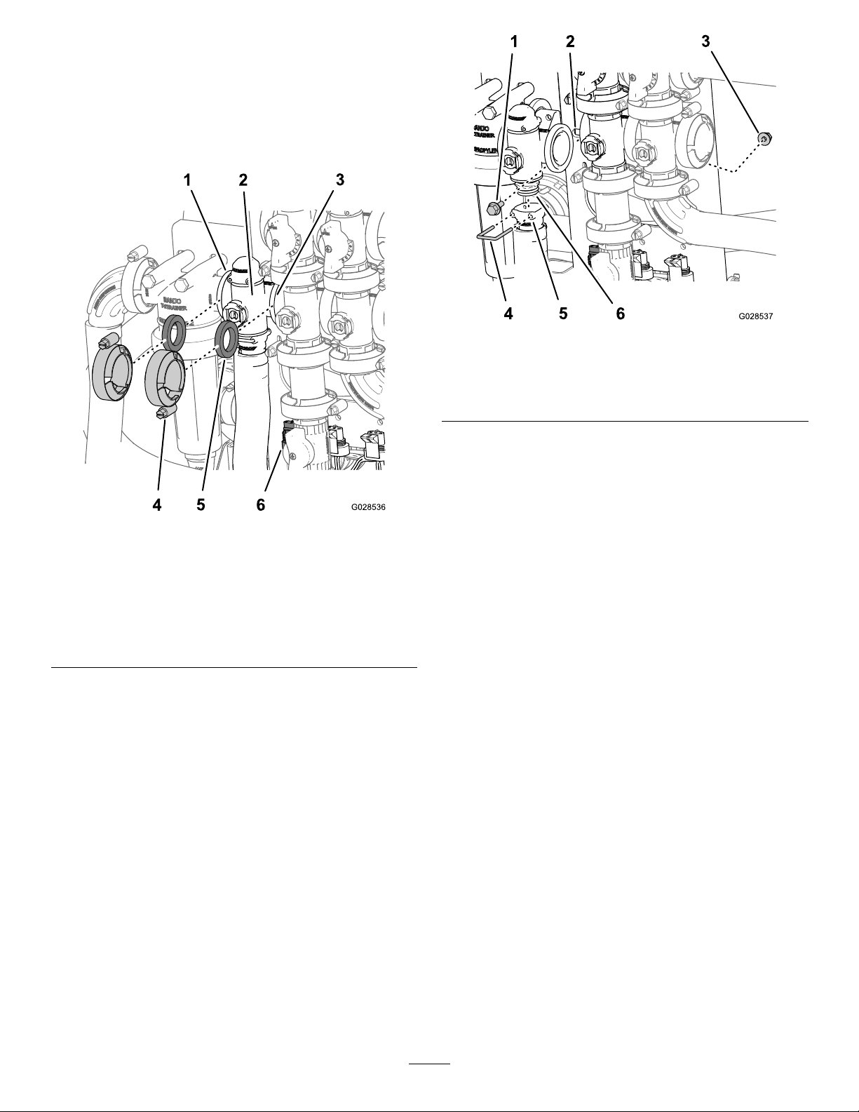
RemovingtheRateControlManifold
Valve
1.Removeclampsandgasketsthatsecurethemanifold
fortheratecontrolvalve(Figure48).
Note:Retaintheclamp(s)andgasket(s)forinstallation
inInstallingtheRateControlManifoldValve(page59).
Figure49
1.Flanged-headbolt4.Retainer
2.Valvemount
3.Flangedlocknut
5.Socket(outlettting)
6.Manifoldvalveassembly
3.Removethe2anged-headboltsand2anged
locknutsthatsecurestheratecontrolvalvetothe
valvemountandremovethevalvemanifoldfromthe
machine(Figure49).
Figure48
1.Flange(pressurelter
head)
2.Manifold(ratecontrol
valve)
3.Flange(agitationvalve)6.3-pinconnector(valve
4.Clamp
5.Gasket
actuator—ratecontrol
valve)
2.Removetheretainerthatsecuretheoutletttingtothe
manifoldfortheratecontrolvalve(Figure49).
Note:Ifnecessary,loosenedthemountinghardware
forthepressurelterheadtoeaseremovaloftherate
controlvalve..
RemovingtheAgitationManifoldValve
1.Removeclampsandgasketsthatsecurethemanifold
fortheagitationvalve(Figure50)totheagitation
bypassvalve,ratecontrolvalve,masterboomvalve,
andadaptertting(agitationthrottlevalve).
Note:Retaintheclamp(s)andgasket(s)forinstallation
inInstallingtheAgitationManifoldValve(page60).
54
Page 55
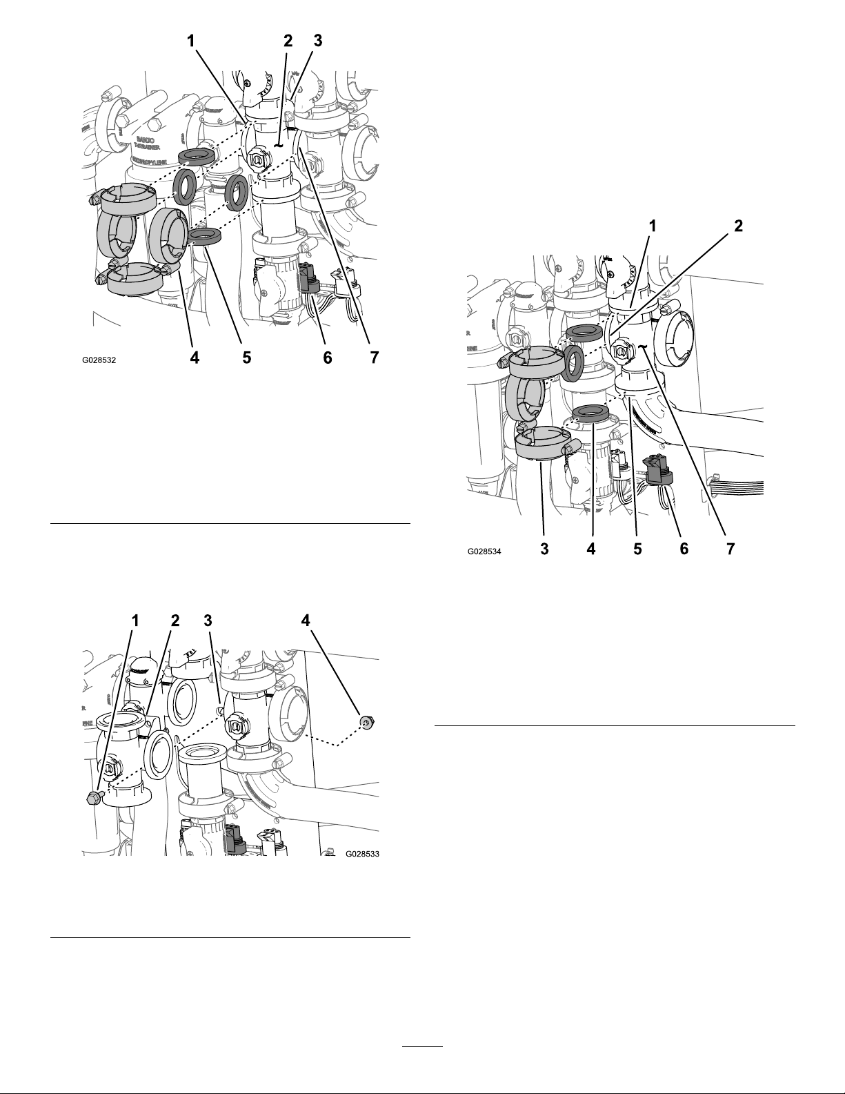
Figure50
RemovingtheMasterBoomManifold
Valve
1.Removeclampsandgasketsthatsecurethemanifold
forthemasterboomvalve(Figure52)tothemaster
boombypassvalve,agitationvalve,and90°anged
elbow(attheendofthehosefortheowmeter).
Note:Retaintheclamp(s)andgasket(s)forinstallation
inInstallingtheMasterBoomManifoldValve(page
61).
1.Flange(pressurelter
head)
2.Manifold(agitationvalve)6.3-pinconnector(valve
3.Flange(bypass
valve—agitationvalve)
4.Clamp
5.Gasket
actuator—agitationvalve)
7.Flange(masterboom
valve)
2.Removetheanged-headboltandangedlocknutthat
securestheagitationvalvetothevalvemountand
removethevalvemanifoldfromthemachine(Figure
51).
Figure52
1.Flange(bypass—master
boomvalve)
2.Flange(agitationvalve)6.3-pinconnector(valve
3.Clamp7.Manifold(masterboom
4.Gasket
5.90°angedelbow
actuator—masterboom
valve)
valve)
2.Removetheanged-headboltandangedlocknutthat
securesthemasterboomvalvetothevalvemountand
removethevalvemanifoldfromthemachine(Figure
53).
Figure51
1.Flanged-headbolt3.Valvemount
2.Manifold(agitationvalve)
4.Flangedlocknut
55
Page 56
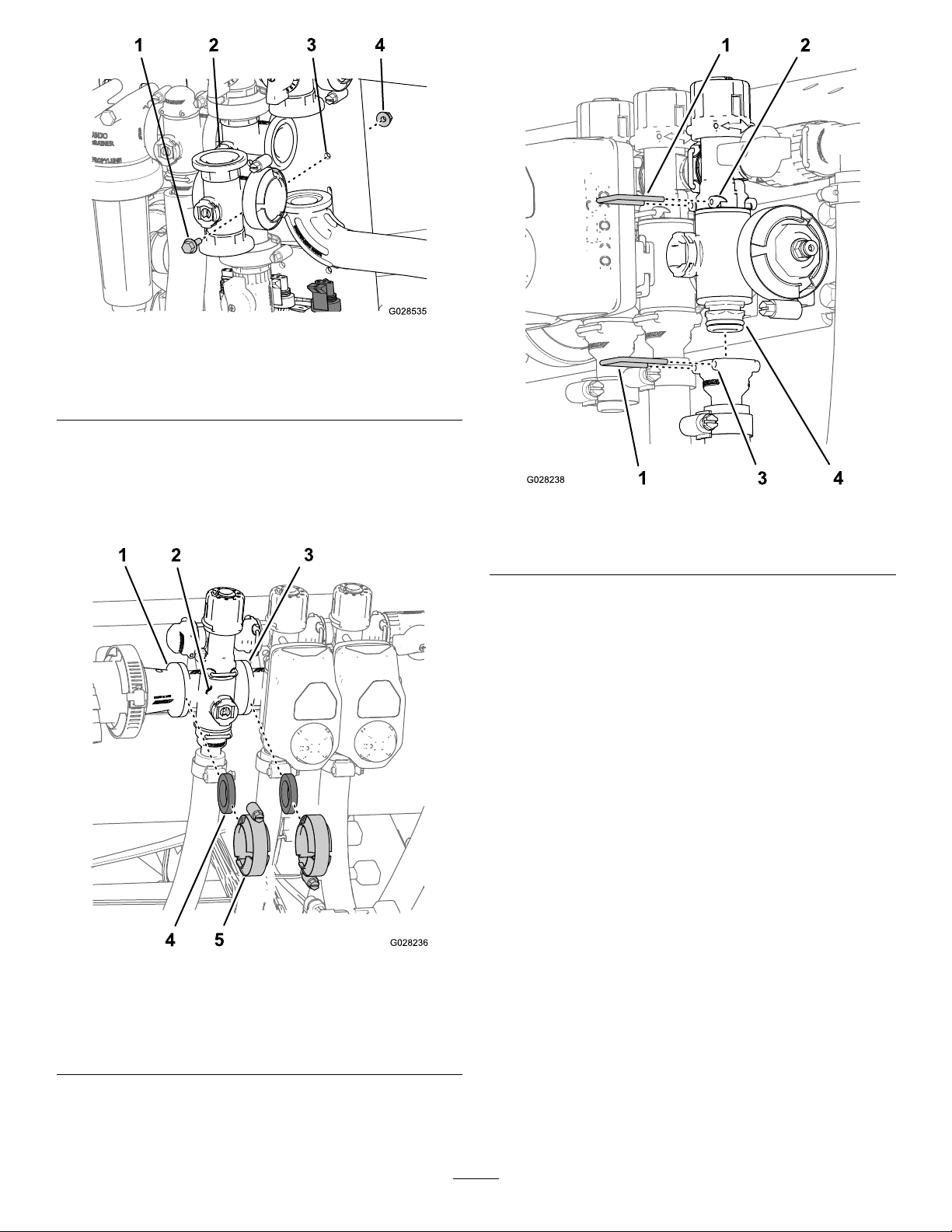
Figure53
1.Flanged-headbolt3.Valvemount
2.Manifold(masterboom
valve)
4.Flangedlocknut
RemovingtheSectionManifoldValve
1.Removeclampsandgasketsthatsecurethemanifold
forthesectionvalve(Figure54)totheadjacentsection
valve(ifleftsectionvalve,andthereducercoupling).
Figure55
1.Retainer
2.Socket(bypasstting)4.Manifoldvalveassembly
3.Socket(outlettting)
3.Fortheleftorrightboomsectionvalves,removethe
anged-headboltsandangedlocknutsthatsecures
thesectionvalve(s)tothevalvemountandremovethe
valvemanifold(s)fromthemachine;forthecenter
sectionvalve,removethesectionvalvemanifoldfrom
themachine(Figure56).
Figure54
1.Flange(reducercoupling)4.Gasket
2.Manifold(sectionvalve)
3.Flange(adjacentsection
valve)
5.Flangeclamp
2.Removetheretainersthatsecuretheoutletttingto
thesectionvalvemanifoldandthevalvemanifoldto
thebypasstting(Figure55).
56
Page 57
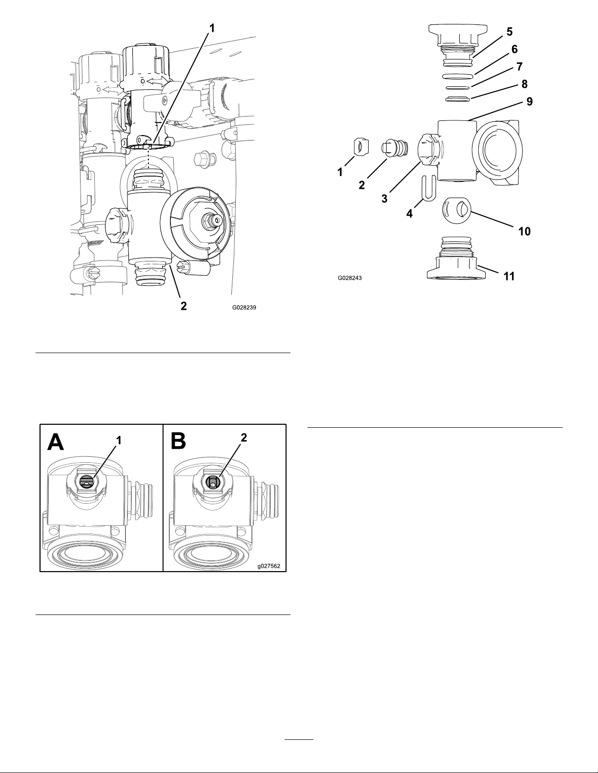
Figure56
1.Bypasstting2.Sectionvalvemanifold
CleaningtheManifoldValve
1.Positionthevalvestemsothatitisintheclosed
position(BofFigure57).
Figure58
AgitationValveManifold
1.Stemretainer7.BackseatingO-ring(0.676
2.Valvestem8.V alveseatring
3.Stemport9.Mainfoldbody
4.Stemcaptureretainer
5.Endcaptting11.Endcapttingassembly
6.EndcapsealO-ring(0.796
inch/0.139inch)
inch/0.07inch)
10.Ballvalve
Figure57
1.Valveopen2.Valveclosed
2.Removethe2endcapttingassemblyfromeachend
ofthemanifoldbody(Figure58andFigure59).
57
Page 58
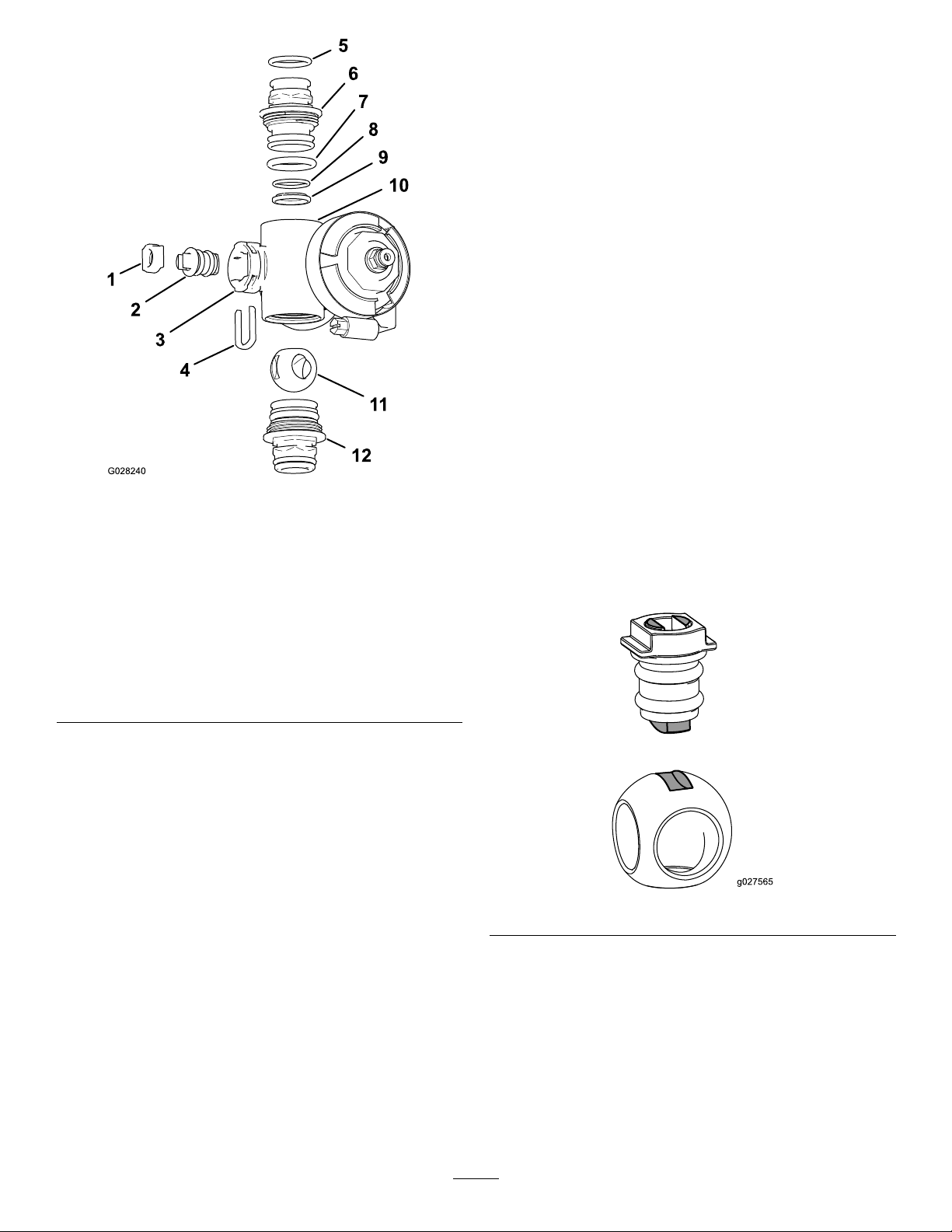
AssemblingtheManifoldValve
1.ChecktheconditionoftheoutletttingO-rings
(sectionvalvemanifoldonly),endcapO-rings,back
seatingO-rings,ballseatfordamageorwear(Figure58
andFigure59).
Note:ReplaceanydamagedorwornO-ringsorseats.
2.Applygreasetothevalvestemandinsertitintothe
valvestemseat(Figure58andFigure59).
3.Installthevalvestemandseatintothemanifoldand
securethestemandseatwiththestemretainer(Figure
58andFigure59).
4.EnsurethatthebackseatingO-ringandtheballseat
arealignedandseatedintotheendcaptting(Figure
58andFigure59)
5.Installtheendcapttingassemblyontothemanifold
bodyuntiltheangeoftheendcapttingtouchesthe
manifoldbody(Figure58andFigure59),thenturnthe
endcapttinganadditional1/8to1/4turn;torquethe
ttingto225to282N-cm(20to25in-lbs).
Figure59
SectionValveManifold
1.Valvestemseat
2.Valvestemassembly
3.Stemport
4.Stemretainer10.Mainfoldbody
5.OutletttingO-ring(0.737
inch/0.103inch)
6.Endcaptting12.Endcapttingassembly
7.EndcapO-ring(0.796inch
/0.139inch)
8.BackseatingO-ring(0.676
inch/0.07inch)
9.Ballseat
11.Ballvalve
3.Turnthevalvestemsothattheballisintheopen
position(AofFigure57).
Note:Thevalvestemwillbeparallelwiththevalve
owandtheballwillslideout.
4.Removethestemretainerfromtheslotsinthestem
portinthemanifold(Figure58andFigure59).
5.Removethestemretainerandvalvestemseatfromthe
manifold(Figure58andFigure59).
Note:Usecautionsoasnottodamagetheendof
thetting.
6.Inserttheballintothevalvebody(Figure60).
Note:Thevalvestemshouldtinsidetheballdrive
slot.Ifthevalvestemdoesnott,adjusttheposition
oftheball(Figure60).
Figure60
6.Reachintothemanifoldbodyandremovethevalve
stemassembly(Figure58andFigure59).
7.Cleantheinsideofthemanifoldandexteriorofthe
ballvalve,valvestemassembly ,stemcapture,andend
ttings.
7.Turnthevalvestemassemblysothatthevalveisclosed
(BofFigure57)
8.Repeatsteps4and5fortheotherendcaptting
assembly.
58
Page 59
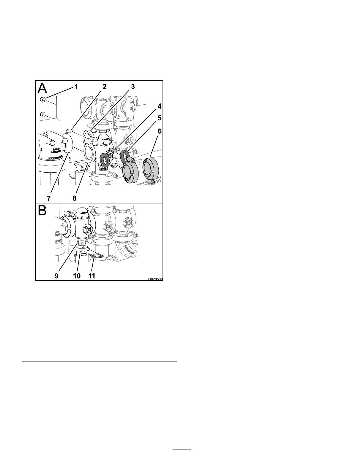
InstallingtheRateControlManifold
Valve
1.Aligna1gasketbetweentheangesoftheratecontrol
valvemanifoldandthepressurelterhead(AofFigure
61).
Note:Ifneeded,loosenthemountinghardwarefor
thepressurelterheadasneededtoprovideclearance.
5.Assembletheratecontrolvalvetothevalvemountwith
the2anged-headboltsand2angedlocknuts(Aof
Figure61)thatyouremovedinstep3ofRemovingthe
RateControlManifoldValve(page54)andtorquethe
nutandboltto1017to1243N-cm(90to110in-lb).
6.Assembletheoutletttingontothelowerendcap
ttingofthemanifoldvalve(BofFigure61).
7.Securetheendcapttingtotheoutletttingby
insertingaretainerintothesocketoftheoutlettting
(BofFigure61).
8.Ifyouloosenedthemountinghardwareforthe
pressurelterhead,tightenthenutandboltto1978to
2542N-cm(175to225in-lb).
Figure61
1.Locknut
2.Valvemount
3.Flange
(agitation
valve)
4.Flanged-head
bolt
5.Gasket9.Manifoldvalve
6.Clamp10.Socket(outlet
7.Flange
(pressurelter
head)
8.Flange(rate
controlvalve)
assembly
tting)
11.Retainer
2.Assembletheratecontrolvalvemanifold,gasket,and
pressurelterheadwithaclamptightenedhandtight
(AofFigure61).
3.Aligna1gasketbetweentheangesoftheratecontrol
valveandtheagitationvalvemanifold(AofFigure61)
4.Assembletheratecontrolvalvemanifold,gasket,and
agitationvalvemanifoldwithaclamptightenedhand
tight(AofFigure61).
59
Page 60
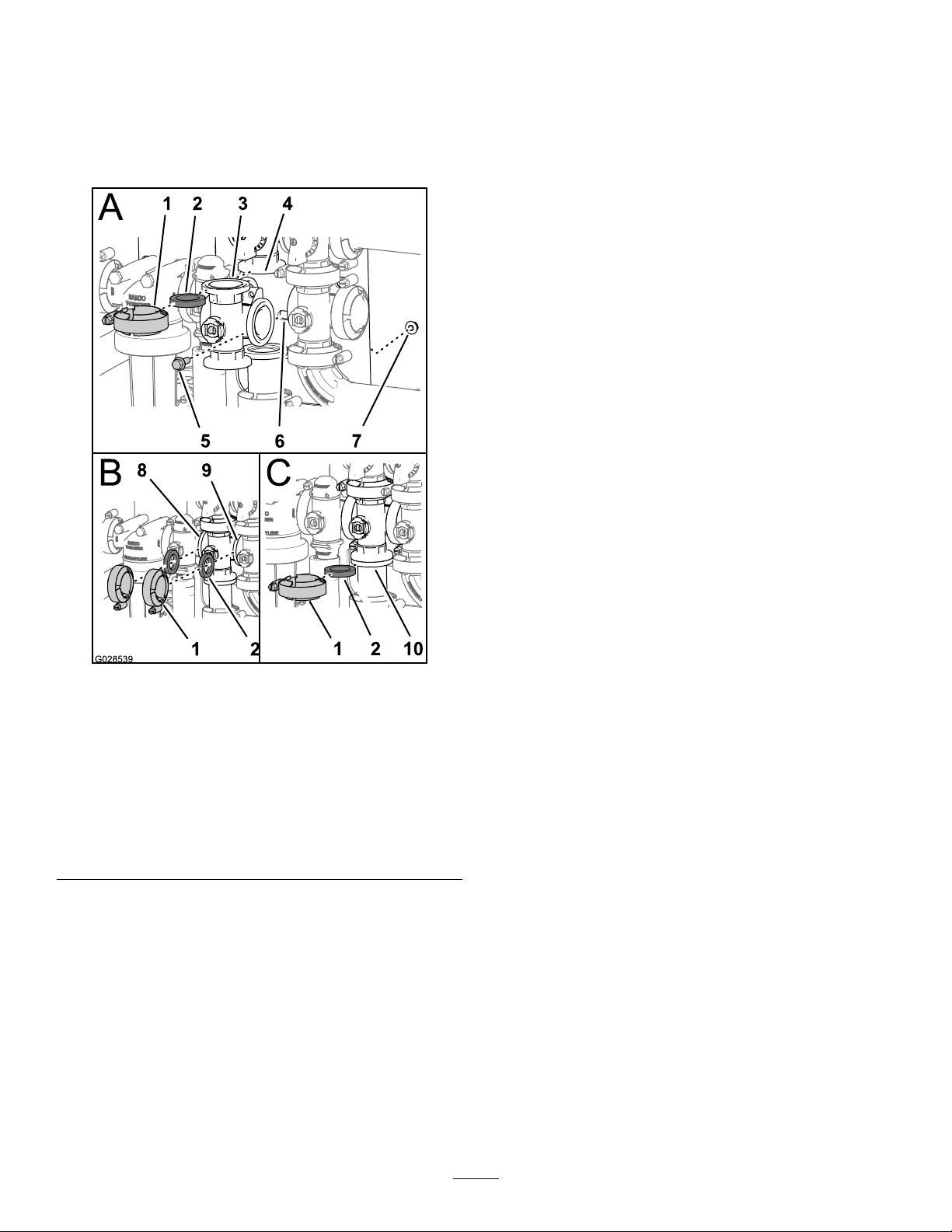
InstallingtheAgitationManifoldValve
1.Aligntheangeoftheagitationvalvemanifold,1
gasket,andtheangeoftheagitationbypassvalve(A
ofFigure62).
Note:Ifneeded,loosenthemountinghardwarefor
themasterboomvalveasneededtoprovideclearance.
6.Assembletheagitationvalvemanifold,gasket,and
masterboomvalvewithaclamptightenedhandtight
(BofFigure62).
7.Aligna1gasketbetweentheangesoftheagitation
valvemanifoldandtheadapterttingfortheagitation
throttlevalve(CofFigure62).
8.Assembletheagitationvalvemanifold,gasket,and
adapterttingwithaclamptightenedhandtight(Cof
Figure62).
9.Assembletheagitationvalvetothevalvemountwith
theanged-headboltandangedlocknutthatyou
removedinstep2ofRemovingtheAgitationManifold
Valve(page54)andtorquethenutandboltto1017to
1243N-cm(90to110in-lb).
10.Ifyouloosenedthemountinghardwareforthemaster
boomvalve,tightenthenutandboltto1978to2542
N-cm(175to225in-lb).
Figure62
1.Flangeclamp6.V alvemount
2.Gasket
3.Manifold(agitationvalve)8.Flange(ratecontrolvalve)
4.Flange
(manifold—agitation
bypassvalve)
5.Flanged-headbolt
7.Flangedlocknut
9.Flange(masterboom
valve)
10.Flange(adapter
tting—agitationthrottle
valve)
2.Assembletheagitationbypassvalve,gasket,and
agitationvalvemanifoldwithaclamptightenedhand
tight(AofFigure62).
3.Aligna1gasketbetweentheangesoftheratecontrol
valveandtheagitationvalvemanifold(BofFigure62).
4.Assembletheratecontrolvalve,gasket,andagitation
valvemanifoldwithaclamptightenedhandtight(Bof
Figure62).
5.Aligna1gasketbetweentheangesoftheagitation
valvemanifoldandthemasterboomvalve(BofFigure
62).
60
Page 61
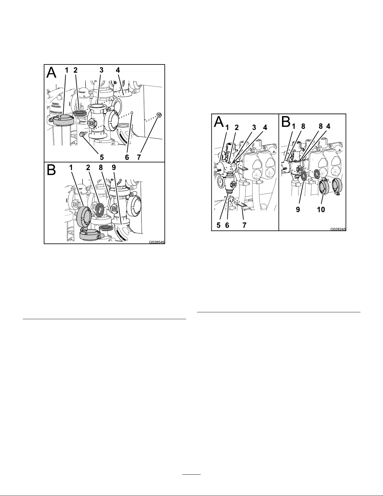
InstallingtheMasterBoomManifold
Valve
1.Aligntheangeofthemasterboomvalvemanifold,1
gasket,andtheangeofthemasterboombypassvalve
(AofFigure63).
7.Assembletheagitationvalvetothevalvemountwith
theanged-headboltandangedlocknutthatyou
removedinstep2ofRemovingtheMasterBoom
ManifoldValve(page55)andtorquethenutandboltto
1017to1243N-cm(90to110in-lb).
InstallingtheSectionManifoldValve
1.Inserttheupperendcapttingofthemanifoldvalve
intothebypasstting(AofFigure64).
Note:Ifneeded,loosenthemountinghardwarefor
thebypassttingasneededtoprovideclearance.
Figure63
1.Flangeclamp6.V alvemount
2.Gasket
3.Manifold(masterboom
valve)
4.Flange(bypass—master
boomvalve)
5.Flanged-headbolt
7.Flangedlocknut
8.Flange(agitationvalve)
9.90°angedelbow
2.Assemblethemasterboomvalvemanifold,gasket,and
masterboombypassvalvewithaclamptightenedhand
tight(AofFigure63).
3.Aligntheangeofthemasterboomvalvemanifold,1
gasket,andtheagitationvalvemanifold(BofFigure
63).
4.Assemblethemasterboomvalvemanifold,gasket,and
agitationvalvemanifoldwithaclamptightenedhand
tight(BofFigure63)
5.Aligntheangeofthemasterboomvalvemanifold,1
gasket,andthe90°angedelbow(attheendofthe
hosefortheowmeter;refertoBofFigure63).
6.Assemblethemasterboomvalvemanifold,gasket,and
90°angedelbowwithaclamptightenedhandtight
(BofFigure63).
Figure64
1.Flange(reducercoupling)6.Socket(outlettting)
2.Socket(bypasstting)
3.Bypasstting8.Flange(manifold—section
4.Flange(adjacent
manifold—agitationvalve)
5.Endcaptting(manifold
valveassembly)
7.Retainer
valve)
9.Gasket
10.Flangeclamp
2.Securetheendcapttingtothebypassttingby
insertingaretainerintothesocketofthebypasstting
(AofFigure64).
3.Assembletheoutletttingontothelowerendcap
ttingofthemanifoldvalve(AofFigure64).
4.Securetheendcapttingtotheoutletttingby
insertingaretainerintothesocketoftheoutlettting
(AofFigure64)
5.Aligna1gasketbetweentheangesofthereducer
couplingandthesectionvalvemanifold(BofFigure
64).
6.Assemblethereducercoupling,gasket,andsection
valvemanifoldwithaclamptightenedhandtight(Bof
Figure64).
7.Ifinstallingthe2leftmostsectionvalves,aligna1
gasketbetweentheangesofthe2adjacentsection
valvemanifolds(BofFigure64).
61
Page 62

8.Assembletheand2adjacentsectionvalvemanifolds
andgasketwithaclamptightenedhandtight(Bof
Figure64).
9.Fortheleftorrightboomsectionvalves,assemble
thevalvestothevalvemountwiththeanged-head
boltandangedlocknutthatyouremovedinstep3
ofRemovingtheSectionManifoldValve(page56)
andtorquethenutsandboltsto1017to1243N-cm
(90to110in-lb).
10.Ifyouloosenedthemountinghardwareforthebypass
tting,tightenthenutandboltto1017to1243N-cm
(90to110in-lb).
InstallingtheValveActuator
1.Aligntheactuatortothemanifoldvalveand(Figure
47).
2.Securetheactuatorandvalvewiththeretainerthatyou
removedinstep3ofRemovingtheValveActuator
(page53).
3.Connectthe3-pinconnectorofthevalveactuator
harnesstothe3-socketconnectorofthewiringharness
ofthesprayer
Storage
1.Positionthesprayeronalevelsurface,settheparking
brake,stopthepump,stoptheengine,andremovethe
ignitionkey .
2.Cleandirtandgrimefromtheentiremachine,including
theoutsideoftheenginecylinderheadnsandblower
housing.
Important:Youcanwashthemachinewithmild
detergentandwater.Donotusehigh-pressure
watertowashthemachine.Pressurewashing
maydamagetheelectricalsystemorwashaway
necessarygreaseatfrictionpoints.Avoidexcessive
useofwater,especiallynearthecontrolpanel,
lights,engine,andthebattery.
3.Cleanthespraysystem;refertotheCleaningthe
Sprayer(page27).
4.Cleanthepistonsinthevalveassembly;referto
CleaningtheSprayerValves(page53).
5.Conditionthesprayersystemasfollows:
A.Drainthefreshwatertank.
B.Drainthespraysystemascompletelyaspossible.
C.Preparerustinhibiting,non-alcoholbased,
RVantifreezesolutionperthemanufacturer's
instructions.
D.AddtheRVantifreezesolutiontothefreshwater
tankandthesprayertank.
E.Runthesprayerpumpforafewminutesto
circulatetheRVantifreezethroughoutthesprayer
systemandanyinstalledsprayaccessories.
F.Drainthefreshwatertankandspraysystemas
completelyaspossible.
6.Usetheboomliftswitchestoraisethebooms.Raise
theboomsuntiltheyhavemovedcompletelyinto
boomtransportcradleformingthe“X”transport
positionandtheboomcylindersarefullyretracted.
Makesuretheboomcylindersarefullyretractedto
preventactuatorroddamage.
7.Inspectthebrakes;refertoInspectingtheBrakes(page
46).
8.Servicetheaircleaner;refertoServicingtheAir
Cleaner(page39).
9.Greasethesprayer;refertotheLubrication(page38).
10.Changethecrankcaseoil;refertoChangingtheEngine
Oil(page40).
11.Checkthetirepressure;refertoCheckingtheTire
Pressure(page22).
12.Forstorageover30days,preparethefuelsystemas
follows:
A.Addapetroleumbasedstabilizer/conditionerto
fuelinthetank.
62
Page 63

Followmixinginstructionsfromstabilizer
manufacturer.Donotuseanalcoholbased
stabilizer(ethanolormethanol).
Note:Afuelstabilizer/conditionerismost
effectivewhenmixedwithfreshgasolineandused
atalltimes.
B.Runtheenginetodistributeconditionedfuel
throughthefuelsystem(5minutes).
C.Stoptheengine,allowittocool,anddrainthe
fueltank.
D.Restarttheengineandrunituntilitstops.
E.Choketheengine.
F.Startandruntheengineuntilitwillnotstartagain.
G.Disposeoffuelproperly.Recycleasperlocal
codes.
Important:Donotstore
stabilizer/conditionedgasolineover90
days
13.Removethesparkplugsandchecktheircondition;
refertoRemovingtheSparkPlug(page41).
23.Removetheignitionkeyandputitinasafeplaceout
ofthereachofchildren.
24.Coverthemachinetoprotectitandkeepitclean.
14.Withthesparkplugsremovedfromtheengine,pour
twotablespoonsofengineoilintothesparkplughole.
15.Usetheelectricstartertocranktheengineand
distributetheoilinsidethecylinder.
16.Installthesparkplugsandtightentorecommended
torque;refertoInstallingtheSparkPlugs(page41).
Note:Donotinstallthewireonthesparkplug(s).
17.Removethebatteryfromthechassis,checkthe
electrolytelevel,andchargeitfully;refertoServicing
theBattery(page43).
Note:Donotconnectthebatterycablestothebattery
postsduringstorage.
Important:Thebatterymustbefullychargedto
preventitfromfreezingandbeingdamagedat
temperaturesbelow0°C(32°F).Afullycharged
batterymaintainsitschargeforabout50days
attemperatureslowerthan4°C(40°F).Ifthe
temperatureswillbeabove4°C(40°F),checkthe
waterlevelinthebatteryandchargeitevery30
days.
18.Checkandtightenallbolts,nuts,andscrews.Repairor
replaceanypartthatisdamaged.
19.Checktheconditionofallsprayhoses,replacingany
thataredamagedorworn.
20.Tightenallhosettings.
21.Paintallscratchedorbaremetalsurfaces.Paintis
availablefromyourAuthorizedServiceDealer.
22.Storethemachineinaclean,drygarageorstoragearea.
63
Page 64

Troubleshooting
TroubleshootingtheEngineandVehicle
Problem
Thestarterdoesnotcrank.
Theenginecranks,butwillnotstart.
Theenginestarts,butdoesnotkeep
running.
PossibleCauseCorrectiveAction
1.Therangeselectorisinagearother
thanNeutral.
2.Theelectricalconnectionsare
corrodedorloose.
3.Afuseisblownorloose.3.Correctorreplacefuse.
4.Thebatteryisdischarged.
5.Thesafetyinterlocksystemis
malfunctioning.
6.Astarterorstartersolenoidisbroken.
7.Theinternalenginecomponentshave
seized.
1.Thefueltankisempty.1.Fillthetankwithfreshfuel.
2.Dirt,water,orstalefuelisinthefuel
system.
3.Thefuellineisclogged.3.Cleanorreplacethefuelsystem.
4.Thesparkplugleadisdisconnected.4.Reconnectthesparkplug.
5.Asparkplugisdamagedordirty.5.Replacethesparkplug.
6.Thekillrelayisnotenergized.
7.Theignitionisbroken.
1.Thefueltankventisrestricted.1.Replacethefuelcap.
2.Dirtorwaterisinthefuelsystem.2.Drainandushthefuelsystem;add
3.Thefuellterisclogged.3.Replacethefuellter.
4.Afuseisblownorloose.4.Correctorreplacethefuse.
5.Thefuelpumpisbroken.5.ContactyourAuthorizedService
6.Thecarburetorisbroken.
7.Thereareloosewiresorpoor
connections.
8.Thecylinderheadgasketisbroken.
1.Pressthebrakepedalandmovethe
rangeselectortotheNeutralposition.
2.Checktheelectricalconnectionsfor
goodcontact.
4.Chargeorreplacethebattery.
5.ContactyourAuthorizedService
Dealer.
6.ContactyourAuthorizedService
Dealer.
7.ContactyourAuthorizedService
Dealer.
2.Drainandushthefuelsystem;add
freshfuel.
6.ContactyourAuthorizedService
Dealer.
7.ContactyourAuthorizedService
Dealer.
freshfuel.
Dealer.
6.ContactyourAuthorizedService
Dealer.
7.Checkandtightenwireconnections.
8.ContactyourAuthorizedService
Dealer.
Theengineruns,butknocksormisses.
1.Dirt,water,orstalefuelisinthefuel
system.
2.Asparkplugleadisloose.2.Reconnectthesparkpluglead.
3.Asparkplugisbroken.3.Replacethesparkplug.
4.Thereareloosewiresorpoor
connections.
5.Theengineisoverheating.
1.Drainandushthefuelsystem;add
freshfuel.
4.Checkandtightenwireconnections.
5.See“Theengineoverheats”below.
64
Page 65

Problem
PossibleCauseCorrectiveAction
Theenginewillnotidle.
Theengineoverheats.
Theenginelosespower.
1.Thefueltankventisrestricted.1.Replacethefuelcap.
2.Dirt,water,orstalefuelisinthefuel
system.
3.Asparkplugisdamagedorbroken.3.Replacethesparkplug.
4.Carburetoridlepassagesareplugged.4.ContactyourAuthorizedService
5.Theidlespeedadjustingscrewis
incorrectlyset.
6.Thefuelpumpisbroken.6.ContactyourAuthorizedService
7.Thereislowcompression.
8.Theaircleanerelementisdirty.
1.Thecrankcaseoillevelisincorrect.
2.Thereisexcessiveloading.2.Reducetheload;uselowerground
3.Theairintakescreensaredirty.
4.Thecoolingnsandairpassages
undertheengineblowerhousing
and/ortherotatingairintakescreen
areplugged.
5.Thefuelmixtureislean.5.ContactyourAuthorizedService
1.Thecrankcaseoillevelisincorrect.
2.Theaircleanerelementisdirty.
3.Dirt,water,orstalefuelisinthefuel
system.
4.Theengineisoverheated.
5.Asparkplugisdamagedordirty.5.Replacethesparkplug.
6.Theventholeinthefueltankvent
ttingisplugged.
7.Thereislowcompression.
2.Drainandushthefuelsystem;add
freshfuel.
Dealer.
5.ContactyourAuthorizedService
Dealer.
Dealer.
7.ContactyourAuthorizedService
Dealer.
8.Cleanorreplacetheelement.
1.Fillordraintothefullmark.
speed.
3.Cleanwitheveryuse.
4.Cleanwitheveryuse.
Dealer.
1.Fillordraintothefullmark.
2.Cleanorreplace.
3.Drainandushthefuelsystem;add
freshfuel.
4.SeeEngineOverheats.
6.Replacethefuelcap.
7.ContactyourAuthorizedService
Dealer.
Themachinewillnotoperateorissluggish
ineitherdirectionbecausetheengine
bogsdownorstalls.
Themachinewillnotoperateineither
direction.
1.Theenginemountingboltsareloose.1.Tightentheenginemountingbolts. Thereisabnormalvibrationornoise.
2.Thereisaproblemwiththeengine.
1.Theparkingbrakeisset.1.Releasetheparkingbrake.
1.TherangeselectorisintheNeutral
position.
2.Theparkingbrakewasnotreleasedor
theparkingbrakeisnotreleasing.
3.Thetransmissionisbroken.
4.Thecontrollinkageneedsadjustment
orreplacement.
5.Thedriveshaftorwheelhubkeyhas
beendamaged.
2.ContactyourAuthorizedService
Dealer.
1.Pressthebrakeandshifttherange
selectorintoagear.
2.Releasetheparkingbrakeorcheck
thelinkage.
3.ContactyourAuthorizedService
Dealer.
4.ContactyourAuthorizedService
Dealer.
5.ContactyourAuthorizedService
Dealer.
65
Page 66

TroubleshootingtheSpraySystem
Problem
Aboomsectiondoesnotspray.
Aboomsectiondoesnotturnoff.
Aboomvalveisleaking.1.Asealiswornordamaged.1.Disassemblethevalveandreplace
Apressuredropoccurswhenyouturnon
aboom.
1.Theelectricalconnectionontheboom
valveisdirtyordisconnected.
2.Thereisablownfuse.2.Checkthefusesandreplacethemas
3.Thereisapinchedhose.3.Repairorreplacethehose.
4.Aboom-sectionbypassisimproperly
adjusted.
5.Therearedamagedboomvalve.
6.Theelectricalsystemisdamaged.
1.Theboom-sectionvalveisdamaged.1.Disassembletheboom-sectionvalve;
1.Theboombypassisimproperly
adjusted.
2.Thereisanobstructionintheboom
valvebody .
3.Anozzlelterisdamagedorclogged.
PossibleCauseCorrectiveAction
1.Turnthevalveoffmanually.Disconnect
theelectricalconnectoronthevalve
andcleanallleads,thenreconnectit.
necessary.
4.Adjusttheboom-sectionbypass.
5.ContactyourAuthorizedService
Dealer.
6.ContactyourAuthorizedService
Dealer.
refertothesectionCleaningthe
SprayerValves.Inspectalloftheparts
andreplaceanythataredamaged.
thesealsusingtheValveRepair
Kit;contactyourAuthorizedService
Dealer.
1.Adjusttheboombypass.
2.Removetheinletandoutlet
connectionstotheboomvalve
andremoveanyobstructions.
3.Removeandinspectallnozzles.
66
Page 67

InternationalDistributorList
Distributor:
AgrolancKft
BalamaPrimaEngineeringEquip.HongKong85221552163
B-RayCorporation
CascoSalesCompany
CeresS.A.CostaRica
CSSCTurfEquipment(pvt)Ltd.SriLanka
CyrilJohnston&Co.
CyrilJohnston&Co.RepublicofIreland
EquiverMexico525553995444ParklandProductsLtd.NewZealand6433493760
FemcoS.A.Guatemala
ForGarderOU
G.Y .K.CompanyLtd.
GeomechanikiofAthensGreece
GolfinternationalTurizm
GuandongGoldenStarChina
HakoGroundandGardenSweden
HakoGroundandGarden
HayterLimited(U.K.)
HydroturfInt.CoDubai
HydroturfEgyptLLC
IrrimacPortugal351212388260T oroEuropeNVBelgium3214562960
IrrigationProductsInt'lPvtLtd.India0091442449
JeanHeybroekb.v.Netherlands3130639461 1VictusEmakPoland48618238369
Country:
Hungary3627539640
Korea82325512076
PuertoRico7877888383
NorthernIreland442890813121
Estonia3723846060
Japan81726325861
Turkey902163365993Riversa
Norway4722907760
UnitedKingdom441279723444
UnitedArabEmirates97143479479T-MarktLogisticsLtd.Hungary3626525500
Egypt2025194308ToroAustraliaAustralia61395807355
PhoneNumber:Distributor:
5062391138
94112746100
442890813121
5024423277
30109350054
862087651338
4635100000
4387
Country:
MaquiverS.A.Colombia
MaruyamaMfg.Co.Inc.
Mountelda.s.CzechRepublic
Mountelda.s.Slovakia
MunditolS.A.
NormaGarden
OslingerTurfEquipmentSA
OyHakoGroundandGarden
Ab
Perfetto
PratoverdeSRL.
Prochaska&Cie
RTCohen2004Ltd.
LelyTurfcare
SolvertS.A.S.
SpyprosStavrinidesLimitedCyprus
SurgeSystemsIndiaLimited
ValtechMorocco21253766
Japan81332522285
Argentina541 14821
Russia74954116120
Ecuador59342396970
Finland35898700733
Poland48618208416
Italy390499128
Austria4312785100
Israel97298617979
Spain
Denmark4566109200
France331308177
India911292299901
Phone
Number:
5712364079
420255704
220
420255704
220
9999
128
34952837500
00
35722434131
3636
EuropeanPrivacyNotice
TheInformationT oroCollects
ToroWarrantyCompany(T oro)respectsyourprivacy .Inordertoprocessyourwarrantyclaimandcontactyouintheeventofaproductrecall,weaskyou
tosharecertainpersonalinformationwithus,eitherdirectlyorthroughyourlocalT orocompanyordealer.
TheT orowarrantysystemishostedonserverslocatedwithintheUnitedStateswhereprivacylawmaynotprovidethesameprotectionasapplies
inyourcountry.
BYSHARINGYOURPERSONALINFORMATIONWITHUS,YOUARECONSENTINGTOTHEPROCESSINGOFYOURPERSONALINFORMATION
ASDESCRIBEDINTHISPRIV ACYNOTICE.
TheWayT oroUsesInformation
Toromayuseyourpersonalinformationtoprocesswarrantyclaims,tocontactyouintheeventofaproductrecallandforanyotherpurposewhichwetell
youabout.ToromayshareyourinformationwithT oro'safliates,dealersorotherbusinesspartnersinconnectionwithanyoftheseactivities.Wewillnot
sellyourpersonalinformationtoanyothercompany.Wereservetherighttodisclosepersonalinformationinordertocomplywithapplicablelawsand
withrequestsbytheappropriateauthorities,tooperateoursystemsproperlyorforourownprotectionorthatofotherusers.
RetentionofyourPersonalInformation
Wewillkeepyourpersonalinformationaslongasweneeditforthepurposesforwhichitwasoriginallycollectedorforotherlegitimatepurposes
(suchasregulatorycompliance),orasrequiredbyapplicablelaw .
Toro'sCommitmenttoSecurityofY ourPersonalInformation
Wetakereasonableprecautionsinordertoprotectthesecurityofyourpersonalinformation.Wealsotakestepstomaintaintheaccuracyandcurrent
statusofpersonalinformation.
AccessandCorrectionofyourPersonalInformation
Ifyouwouldliketorevieworcorrectyourpersonalinformation,[email protected].
AustralianConsumerLaw
AustraliancustomerswillnddetailsrelatingtotheAustralianConsumerLaweitherinsidetheboxoratyourlocalT oroDealer.
374-0269RevH
Page 68

ToroGeneralCommercialProductWarranty
ATwo-YearLimitedWarranty
ConditionsandProductsCovered
TheToroCompanyanditsafliate,ToroWarrantyCompany,pursuant
toanagreementbetweenthem,jointlywarrantyourT oroCommercial
product(“Product”)tobefreefromdefectsinmaterialsorworkmanship
fortwoyearsor1500operationalhours*,whicheveroccursrst.This
warrantyisapplicabletoallproductswiththeexceptionofAerators
(refertoseparatewarrantystatementsfortheseproducts).Wherea
warrantableconditionexists,wewillrepairtheProductatnocosttoyou
includingdiagnostics,labor,parts,andtransportation.Thiswarranty
beginsonthedatetheProductisdeliveredtotheoriginalretailpurchaser.
*Productequippedwithanhourmeter.
InstructionsforObtainingWarrantyService
YouareresponsiblefornotifyingtheCommercialProductsDistributoror
AuthorizedCommercialProductsDealerfromwhomyoupurchasedthe
Productassoonasyoubelieveawarrantableconditionexists.Ifyouneed
helplocatingaCommercialProductsDistributororAuthorizedDealer,or
ifyouhavequestionsregardingyourwarrantyrightsorresponsibilities,
youmaycontactusat:
ToroCommercialProductsServiceDepartment
ToroWarrantyCompany
811 1LyndaleAvenueSouth
Bloomington,MN55420-1196
952–888–8801or800–952–2740
E-mail:[email protected]
OwnerResponsibilities
AstheProductowner,youareresponsibleforrequiredmaintenanceand
adjustmentsstatedinyourOperator'sManual.Failuretoperformrequired
maintenanceandadjustmentscanbegroundsfordisallowingawarranty
claim.
ItemsandConditionsNotCovered
Notallproductfailuresormalfunctionsthatoccurduringthewarranty
periodaredefectsinmaterialsorworkmanship.Thiswarrantydoesnot
coverthefollowing:
•Productfailureswhichresultfromtheuseofnon-T ororeplacement
parts,orfrominstallationanduseofadd-on,ormodiednon-Toro
brandedaccessoriesandproducts.Aseparatewarrantymaybe
providedbythemanufactureroftheseitems.
•Productfailureswhichresultfromfailuretoperformrecommended
maintenanceand/oradjustments.Failuretoproperlymaintainyour
ToroproductpertheRecommendedMaintenancelistedinthe
Operator’sManualcanresultinclaimsforwarrantybeingdenied.
•ProductfailureswhichresultfromoperatingtheProductinanabusive,
negligent,orrecklessmanner.
•Partssubjecttoconsumptionthroughuseunlessfoundtobedefective.
Examplesofpartswhichareconsumed,orusedup,duringnormal
Productoperationinclude,butarenotlimitedto,brakepadsand
linings,clutchlinings,blades,reels,rollersandbearings(sealedor
greasable),bedknives,sparkplugs,castorwheelsandbearings,tires,
lters,belts,andcertainsprayercomponentssuchasdiaphragms,
nozzles,andcheckvalves,etc.
•Failurescausedbyoutsideinuence.Conditionsconsideredtobe
outsideinuenceinclude,butarenotlimitedto,weather,storage
practices,contamination,useofunapprovedfuels,coolants,lubricants,
additives,fertilizers,water,orchemicals,etc.
•Failureorperformanceissuesduetotheuseoffuels(e.g.gasoline,
diesel,orbiodiesel)thatdonotconformtotheirrespectiveindustry
standards.
•Normalnoise,vibration,wearandtear ,anddeterioration.
•Normal“wearandtear”includes,butisnotlimitedto,damagetoseats
duetowearorabrasion,wornpaintedsurfaces,scratcheddecalsor
windows,etc.
Parts
Partsscheduledforreplacementasrequiredmaintenancearewarranted
fortheperiodoftimeuptothescheduledreplacementtimeforthatpart.
Partsreplacedunderthiswarrantyarecoveredforthedurationofthe
originalproductwarrantyandbecomethepropertyofT oro.T orowillmake
thenaldecisionwhethertorepairanyexistingpartorassemblyorreplace
it.T oromayuseremanufacturedpartsforwarrantyrepairs.
DeepCycleandLithium-IonBatteryWarranty:
DeepcycleandLithium-Ionbatterieshaveaspeciedtotalnumberof
kilowatt-hourstheycandeliverduringtheirlifetime.Operating,recharging,
andmaintenancetechniquescanextendorreducetotalbatterylife.Asthe
batteriesinthisproductareconsumed,theamountofusefulworkbetween
chargingintervalswillslowlydecreaseuntilthebatteryiscompletelyworn
out.Replacementofwornoutbatteries,duetonormalconsumption,
istheresponsibilityoftheproductowner.Batteryreplacementmaybe
requiredduringthenormalproductwarrantyperiodatowner’sexpense.
Note:(Lithium-Ionbatteryonly):ALithium-Ionbatteryhasapartonly
proratedwarrantybeginningyear3throughyear5basedonthetime
inserviceandkilowatthoursused.RefertotheOperator'sManualfor
additionalinformation.
MaintenanceisatOwner’sExpense
Enginetune-up,lubrication,cleaningandpolishing,replacementoflters,
coolant,andcompletingrecommendedmaintenancearesomeofthe
normalservicesT oroproductsrequirethatareattheowner’sexpense.
GeneralConditions
RepairbyanAuthorizedToroDistributororDealerisyoursoleremedy
underthiswarranty.
NeitherTheToroCompanynorToroWarrantyCompanyisliablefor
indirect,incidentalorconsequentialdamagesinconnectionwiththe
useoftheToroProductscoveredbythiswarranty,includingany
costorexpenseofprovidingsubstituteequipmentorserviceduring
reasonableperiodsofmalfunctionornon-usependingcompletion
ofrepairsunderthiswarranty.ExceptfortheEmissionswarranty
referencedbelow,ifapplicable,thereisnootherexpresswarranty.All
impliedwarrantiesofmerchantabilityandtnessforusearelimitedto
thedurationofthisexpresswarranty.
Somestatesdonotallowexclusionsofincidentalorconsequential
damages,orlimitationsonhowlonganimpliedwarrantylasts,sotheabove
exclusionsandlimitationsmaynotapplytoyou.Thiswarrantygivesyou
speciclegalrights,andyoumayalsohaveotherrightswhichvaryfrom
statetostate.
Noteregardingenginewarranty:
TheEmissionsControlSystemonyourProductmaybecoveredby
aseparatewarrantymeetingrequirementsestablishedbytheU.S.
EnvironmentalProtectionAgency(EP A)and/ortheCaliforniaAirResources
Board(CARB).Thehourlimitationssetforthabovedonotapplytothe
EmissionsControlSystemWarranty.RefertotheEngineEmissionControl
WarrantyStatementsuppliedwithyourproductorcontainedintheengine
manufacturer’sdocumentationfordetails
CountriesOtherthantheUnitedStatesorCanada
CustomerswhohavepurchasedT oroproductsexportedfromtheUnitedStatesorCanadashouldcontacttheirT oroDistributor(Dealer)toobtain
guaranteepoliciesforyourcountry ,province,orstate.IfforanyreasonyouaredissatisedwithyourDistributor'sserviceorhavedifcultyobtaining
guaranteeinformation,contacttheT oroimporter.
374-0253RevC
 Loading...