

Page 1
© 2014 Toro Australia Pty Ltd
Micro-Master Touch User Guide
Micro-Master
®
Series
Page 2

Page 3

Micro-Master Series by Toro
Micro-Master Touch User Guide
by Toro Australia Pty Ltd
Congratulations on purchasing a Micro-Master Touch Irrigation Controller.
The Micro-Master Touch Controller represents a significant change in the
capabilities of irrigation controllers.
Some of the Micro-Master Touch features include
Touch Screen Control
Modular Construction for ease of expansion and repair
Life Support
Powerful Rules capability
Multiple Pump Sets
Multiple Filter Banks
In-field upgrades
Extensive connectivity options
Direct communications
USB, RS232, RS485
Modems
Analog,
GSM
Internet
GPRS Modem
Ethernet,
Wireless LAN
Toro Australia Pty Ltd
53 Howards Road
Beverley SA 5009
A.B.N. 47 001 310 443
Customer Service Phone: 1300 130 898
Fax: 08 8234 2940
Page 4

All rights reserved. No parts of this work may be reproduced in any form or by any means - graphic,
electronic, or mechanical, including photocopying, recording, taping, or information storage and retrieval
systems - without the written permission of the publisher.
Products that are referred to in this document may be either trademarks and/or registered trademarks of the
respective owners. The publisher and the author make no claim to these trademarks.
While every precaution has been taken in the preparation of this document, the publisher and the author
assume no responsibility for errors or omissions, or for damages resulting from the use of information
contained in this document or from the use of programs and source code that may accompany it. In no
event shall the publisher and the author be liable for any loss of profit or any other commercial damage
caused or alleged to have been caused directly or indirectly by this document.
Digital copies of this manual in various formats are available for download from
http://www.tdssoftware.com.au/manuals/
Printed: June 2014 in Australia.
Technical support for the Micro-Master Touch Controller can be obtained from:
Toro Technical Services
53 Howards Road
Beverley SA 5009
A.B.N. 47 001 310 443
Customer Service Phone: 1300 130 898
Fax: 08 8234 2940
For service or repair, contact:
TDS Software Solutions Pty Ltd
Unit 11 / 78 Morrow Rd,
Lonsdale
South Australia, 5160
Phone: +61 8 8383 6851
Mobile: 0414 645 171
Email: david@tdssoftware.com.au
Web: www.tdssoftware.com.au
Micro-Master Forum: forum.tdssoftware.com.au
Micro-Master Touch User Guide
© 2014 Toro Australia Pty Ltd
Page 5

Micro-Master Touch User Guide
i
© 2014 Toro Australia Pty Ltd Ver 1.2, June 2014
Table of Contents
Foreword
0
1 Introduction
1
................................................................................................................................... 1
1.1
Controller Capabilites
................................................................................................................................... 2
1.2
Do's & Dont's
2 About This Manual
3
3 Controller Part Numbers
4
4 Installation Instructions
7
................................................................................................................................... 7
4.1
Wall Mount Installation
................................................................................................................................... 7
4.2
Module Installation
................................................................................................................................... 9
4.3
Master/Remote selection
................................................................................................................................... 10
4.4
Connecting Valve Wire
................................................................................................................................... 11
4.5
Earth Stake
................................................................................................................................... 11
4.6
Standby Battery
................................................................................................................................... 11
4.7
12 Volt DC Operation
5 Controller Setup and Configuration
13
................................................................................................................................... 13
5.1
Overview
................................................................................................................................... 15
5.2
Setup Selection
................................................................................................................................... 17
5.3
System Setup and Upgrade
................................................................................................................................... 18
5.4
Unit Configuration
................................................................................................................................... 19
5.5
Expansion Module Configuration
................................................................................................................................... 21
5.6
Radio-Master for Touch Field Modules
................................................................................................................................... 26
5.7
Communication Module Options
................................................................................................................................... 28
5.8
PIN Number Setup
................................................................................................................................... 28
5.9
Commissioning Table
................................................................................................................................... 30
5.10
Global Setup
6 Micro-Master Touch Screen Introduction
32
7 Home Screen
35
8 Status Screen
37
9 Multi Station Programs
38
................................................................................................................................... 38
9.1
Overview and Operation
................................................................................................................................... 43
9.2
Program Edit Screens
.......................................................................................................................................................... 43
Program List 9.2.1
.......................................................................................................................................................... 44
Program Edit - Sequential 9.2.2
.......................................................................................................................................................... 46
Program Edit - Grouping 9.2.3
Page 6

Micro-Master Touch User Guide
ii
© 2014 Toro Australia Pty Ltd Ver 1.2, June 2014
.......................................................................................................................................................... 47
Chemical Edit 9.2.4
.......................................................................................................................................................... 48
Irrigation, Cycles and Start Times 9.2.5
.......................................................................................................................................................... 49
Program Mode and Units 9.2.6
.......................................................................................................................................................... 50
Program Delays 9.2.7
.......................................................................................................................................................... 51
Control Inputs 9.2.8
.......................................................................................................................................................... 52
Pumps, Filters and Flow Meters 9.2.9
.......................................................................................................................................................... 53
Program Status and Totals 9.2.10
10 Single Station Programs
54
................................................................................................................................... 54
10.1
Overview and Operation
................................................................................................................................... 56
10.2
Station List
................................................................................................................................... 58
10.3
Station Edit
................................................................................................................................... 59
10.4
Station Advanced Parameters
11 Pump Sets
64
................................................................................................................................... 64
11.1
Overview and Operation
................................................................................................................................... 66
11.2
Pump Set List
................................................................................................................................... 67
11.3
Pump Set Edit
................................................................................................................................... 68
11.4
Pump Set Advanced Parameters
12 Filter Banks
71
................................................................................................................................... 71
12.1
Overview and Operation
................................................................................................................................... 73
12.2
Filter Bank List
................................................................................................................................... 74
12.3
Filter Bank Edit
................................................................................................................................... 75
12.4
Filter Bank Advanced Parameters
13 Chemicals
77
................................................................................................................................... 77
13.1
Overview and Operation
................................................................................................................................... 79
13.2
Chemical List
................................................................................................................................... 80
13.3
Chemical Edit
................................................................................................................................... 81
13.4
Chemical Advanced Parameters
14 Control Sensors
82
................................................................................................................................... 82
14.1
Overview and Operation
................................................................................................................................... 83
14.2
Sensor Selection
................................................................................................................................... 84
14.3
Rules
.......................................................................................................................................................... 84
Overview and Operation 14.3.1
.......................................................................................................................................................... 86
Rules List 14.3.2
.......................................................................................................................................................... 87
Rules Edit 14.3.3
.......................................................................................................................................................... 88
Rule Status and Totals 14.3.4
................................................................................................................................... 88
14.4
Flow Meters
.......................................................................................................................................................... 88
Overview and Operation 14.4.1
.......................................................................................................................................................... 91
Flow Meter List 14.4.2
.......................................................................................................................................................... 92
Flow Meter Edit 14.4.3
.......................................................................................................................................................... 94
Flow Meter Status and Totals 14.4.4
................................................................................................................................... 94
14.5
Aggregate Flow Meters
.......................................................................................................................................................... 94
Overview and Operation 14.5.1
Page 7

Micro-Master Touch User Guide
iii
© 2014 Toro Australia Pty Ltd Ver 1.2, June 2014
.......................................................................................................................................................... 96
Aggregate Flow Meter List 14.5.2
.......................................................................................................................................................... 97
Aggregate Flow Meter Edit 14.5.3
.......................................................................................................................................................... 98
Aggregate Status and Totals 14.5.4
................................................................................................................................... 99
14.6
Digital Sensors
.......................................................................................................................................................... 99
Overview and Operation 14.6.1
.......................................................................................................................................................... 100
Digital List 14.6.2
.......................................................................................................................................................... 101
Digital Edit 14.6.3
.......................................................................................................................................................... 102
Digital Status and Totals 14.6.4
................................................................................................................................... 102
14.7
Rain Bucket
.......................................................................................................................................................... 102
Overview and Operation 14.7.1
.......................................................................................................................................................... 104
Rain Bucket Edit 14.7.2
................................................................................................................................... 105
14.8
Analogue Sensors
.......................................................................................................................................................... 105
Overview and Operation 14.8.1
.......................................................................................................................................................... 107
Analogue List 14.8.2
.......................................................................................................................................................... 108
Analogue Edit 14.8.3
.......................................................................................................................................................... 110
Analogue Status and Totals 14.8.4
................................................................................................................................... 110
14.9
Switch Sensors
.......................................................................................................................................................... 110
Overview and Operation 14.9.1
.......................................................................................................................................................... 112
Switch Sensor List 14.9.2
.......................................................................................................................................................... 113
Switch Sensor Edit 14.9.3
.......................................................................................................................................................... 114
Switch Input Status and Totals 14.9.4
15 Manual Spot Watering
115
................................................................................................................................... 115
15.1
Overview and Operation
................................................................................................................................... 115
15.2
Manual Operation
16 Reports
118
................................................................................................................................... 118
16.1
Overview
................................................................................................................................... 118
16.2
Report Selection
................................................................................................................................... 119
16.3
Report List
................................................................................................................................... 120
16.4
Report Edit
................................................................................................................................... 121
16.5
Report Settings
17 Life Support
123
................................................................................................................................... 123
17.1
Overview
................................................................................................................................... 124
17.2
Life Support Screen
18 Generic Edit Screens
126
................................................................................................................................... 126
18.1
Text Edit
................................................................................................................................... 126
18.2
Number Edit
................................................................................................................................... 127
18.3
Time Edit
................................................................................................................................... 128
18.4
Group Edit
................................................................................................................................... 128
18.5
Allocated Station Edit
................................................................................................................................... 129
18.6
Control / Sensor Selection
................................................................................................................................... 130
18.7
Log View
19 TMR1 Series Remote
131
Page 8

Micro-Master Touch User Guide
iv
© 2014 Toro Australia Pty Ltd Ver 1.2, June 2014
20 Technical Specifications
132
21 Fault Finding
135
................................................................................................................................... 135
21.1
Overview
................................................................................................................................... 136
21.2
Fault Finding Flow Chart
................................................................................................................................... 136
21.3
Fault Finding - Possible Cause
................................................................................................................................... 137
21.4
Diagnostics
................................................................................................................................... 138
21.5
Checking Field Wiring and Valve Currents
................................................................................................................................... 139
21.6
Voltage On Unused Pins
22 Copyright Notice
141
23 Glossary of Terms
142
Page 9

Micro-Master Touch User Guide
1
© 2014 Toro Australia Pty Ltd Ver 1.2, June 2014
1 Introduction
The Micro-Master Touch Irrigation Controller is the latest in a long line of reliable Australian designed
and built controllers brought to you by Toro. It uses the latest in microprocessor technology, including
a full colour, touch screen LCD display.
Each controller consists of a Master Unit, and up to 4 Remote Units.
The Master Unit is supplied with one 8 Station Module, and can be expanded with 8 Station Modules
up to a total of 32 Stations.
Remote Units are supplied with one 8 Station Module, and can be expanded with 8 Station Modules
up to a total of 32 Stations.
It is not necessary to expand each unit before another Remote Unit is added to the controller. Since
each Remote Unit has it's own power supply and is physically separate from the Master Unit, Remote
Units can be placed in different locations to the Master Unit. For example, the Master Unit could be
located in the main office, and an Expansion Unit could be located in the pump shed, and used to
control the pumps, filters and chemical injection system.
1.1
Controller Capabilites
The Micro-Master Touch controller supports various expansion and communication cards.
Expansion Modules include 8 station modules, digital input modules, and analogue input modules.
Communication cards include RS232 modules, Analogue/GSM/GPRS Modem interface modules,
RS485 modules, USB modules, and Ethernet interface cards.
Each Micro-Master Touch controller can be expanded out to 160 stations using additional Remote
controller units (up to 4 units). Communication between units is achieved by RS485 communication
modules or through the addition of the Radio-Master for Touch range of wireless modules.
The Touch Controller supports 32 individual irrigation programs. Each program operates
independently and can be in sequential or grouping mode. Irrigation Programs can be independently
Enabled, (Rain Switched). There are two levels of globally enabling irrigation programs. A global
enable and rain switch stops all idle programs from starting but allows currently active programs to
complete. Individual programs can be set to ignore the rain switch control.
Programs have the following capabilities:
· Irrigation Units can be seconds, minutes or volumetric,
· Chemical Injection Units can be set independently of the main program. Each chemical has it's
own units and may be seconds, minutes, or volumetric.
· 14 day daytable. Each day can have different number of cycles, and include or exclude chemical
injection,
· Up to 8 start times,
· 4 chemicals per group or station,
· Up to 48 groups with up to 40 Stations per group,
· Water budget percentage, 0 to 250%,
· Individual external inputs for starting, stopping, holding and skipping groups/stations,
· Individual Flow Meters for each program, pump, and chemical,
· Staggered programs, where the completion of one program can start another,
· Filter bank support,
· Pump set support.
The chemical system supports up to eight chemicals.
Each chemical has individual prewet/mixing times and can be assigned to any station outputs in the
Page 10

Micro-Master Touch User Guide
2
© 2014 Toro Australia Pty Ltd Ver 1.2, June 2014
controller.
Any four of the eight chemicals can be associated with each program.
The Filter Bank system supports up to eight separate banks of filters.
Each filter bank may contain up to eight filters, and each filter can be assigned to any station output
in the controller.
The Pump Set system supports up to eight separate sets of pumps.
Each pump set may contain up to four pumps, and each pump can be assigned to any station output
in the controller.
Each pump set supports runtime levelling, priority, and can support a VFD as pump 1.
1.2
Do's & Dont's
The Micro-Master Touch controller will give you many years of faithful service, as do all Micro-Master
products, but there are certain requirements that should be observed when using the controller, as
with all electrical equipment.
· Don't leave the door open when you have finished with the controller. Water entering into the
controller via an open door is not covered by your warranty. A burst pipe in a pump shed, for
example, can do a lot of damage.
· Do ensure that all wiring holes in the case are sealed. Ants, mice and slugs can also destroy the
unit if they are allowed entry and will not be covered by your warranty.
· Don't use metal objects to select icons on the LCD screen. You can destroy the touch pad. A
finger, eraser tipped pencil or wand is all that is needed.
· Don't mount the unit where it is exposed to full sun during the day. Temperatures within the unit
may become excessive causing it to fail. Always supply some shade from the elements.
· Do install a backup battery. This will support the unit during any minor power outages.
· Don't use any chemical products to clean the LCD display. A slightly moist clean cloth is all that is
required to lightly wipe away any marks.
· Do use an earthed power source as this will supply greater protection for the unit.
· Don't open up the 240v AC side of the controller. These voltages can be lethal, particularly
if water has entered the case. Always use a licensed support person or return the unit for repair.
· In areas with known voltage fluctuations, or frequent 'brownouts', we recommend that the controller
be connected to a UPS and surge protection device.
Page 11
Micro-Master Touch User Guide
3
© 2014 Toro Australia Pty Ltd Ver 1.2, June 2014
2 About This Manual
Digital interactive copies of this manual in various formats are available for download from http://
www.tdssoftware.com.au/manuals/
This manual (in digital form) has been designed to be context sensitive, and includes many topic links
and image hotspots.
Clicking a button in an image will, where possible, cause a jump to the same screen as if the button
were clicked on the physical Touch controller.
Where not possible or appropriate, the hotspot links to a paragraph explaining the purpose of the
button.
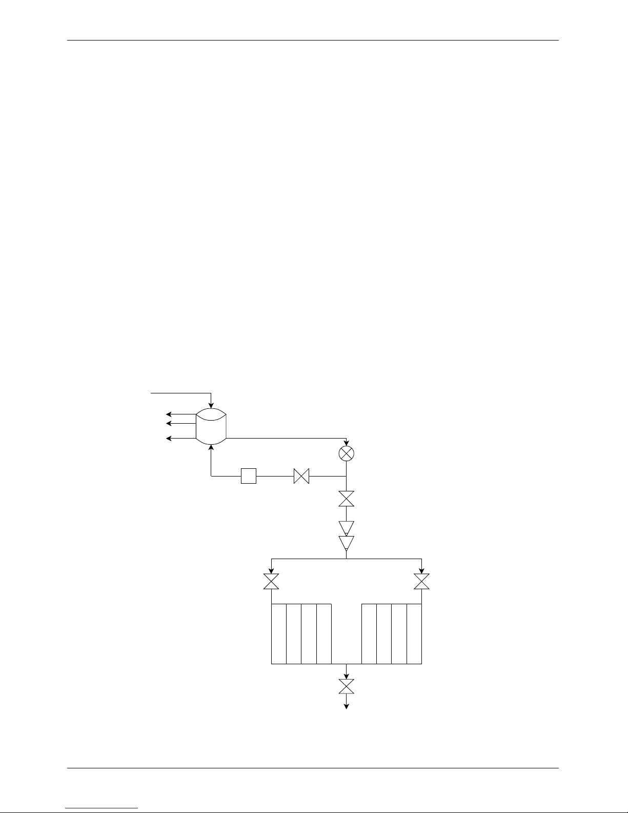
Where appropriate, examples in this manual have been drawn from a real world example.
In this example, a treelot is irrigated using recycled water from a storage tank. There are two zones
in the treelot, allocated to Stations 1 and 2, and a flushing valve (station 4) is connected to both
zones to drain solids from the line after irrigation. The treelot irrigation program operates in grouping
mode. The storage tank is circulated with a five minute on, five minute off cycle repeating 6 times
each shift, running four times every day. Two master valves are connected to the irrigation (station
5) and circulation (station 6) mainlines A pump is connected to station 7, an ozone generator is
connected to station 11, and two filters in a single bank are connected to stations 9 and 10. Chemical
injection is performed each treelot irrigation. Three level sensors detect when the tank is empty,
almost full, and full. The empty and full sensors control the treelot irrigation, and the almost full
sensor stops the ozone generator, and stops the circulation program.
A diagram of the real world example is shown below.
1 2
5
6
7
9
10
11
4
Tank Full
Tank Empty
Almost Full
(Circulation Stop)
Treelot
Zone 1
Treelot
Zone 2
Figure 1 - Real World Example Schematic
Page 12

Micro-Master Touch User Guide
4
© 2014 Toro Australia Pty Ltd Ver 1.2, June 2014
3 Controller Part Numbers
The Micro-Master Touch controller is a modular design.
The Master Unit is supplied as a minimum, with one 8 Station Module, and can be expanded with 8
Station Modules up to a total of 32 Stations.
Remote Units are supplied as a minimum, with one 8 Station Module, and can be expanded with 8
Station Modules up to a total of 32 Stations.
It is not necessary to expand each unit before another Remote Unit is added to the controller. Since
each Remote Unit has it's own power supply and is physically separate from the Master Unit, Remote
Units can be placed in different locations to the Master Unit. For example, the Master Unit could be
located in the main office with one 8 Station Module, and an Expansion Unit could be located in the
pump shed, and used to control the pumps, filters and chemical injection system with multiple 8
Station Modules.
Product Description
MMTOUCH-MST8 / 16 / 24 / 32 Micro-Master Touch Master Unit, 8, 16, 24, 32 station variants
MMTOUCH-REM8 / 16 / 24 / 32 Micro-Master Touch Remote Unit, 8, 16, 24, 32 station
variants
MMTOUCH-STN Micro-Master Touch 8 Station Relay Module
MMTOUCH-DIG Micro-Master Touch 8 Input Digital Input Module
MMTOUCH-ANL Micro-Master Touch 8 Input Analogue Input Module
MMTOUCH-485E Micro-Master Touch RS485 Remote Communication Module
MMTOUCH-485C Micro-Master Touch RS485 Master Communication Module
MMTOUCH-USB Micro-Master Touch USB Communication Module
MMTOUCH-ETH Micro-Master Touch Ethernet Communication Module
MMTOUCH-232 Micro-Master Touch RS232 Communication Module
MMTOUCH-MDM Micro-Master Touch Modem Communication Module
MMTOUCH-WIF Micro-Master Touch WiFi Communication Module
RMT200 Radio-Master for Touch Radio Expansion Module
RMT100 Radio-Master for Touch PC Radio
RMT800 Radio-Master for Touch 8 Station Field Module
RMT440A Radio-Master for Touch 4 Station, 4 Analog Input Field
Module
RMT440D Radio-Master for Touch 4 Station, 4 Digital Input Field Module
RMT-ANT Radio-Master for Touch Antenna
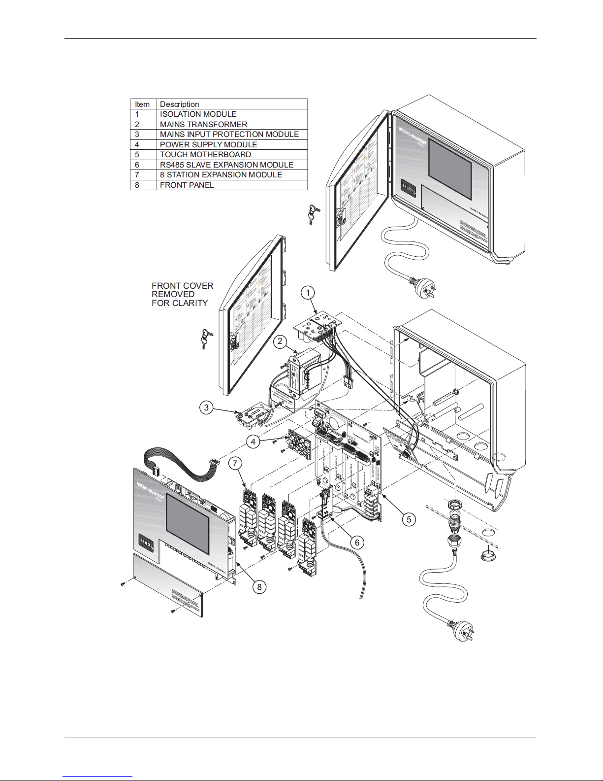
Spare Parts Description
(refer Exploded Diagrams Figs 2 & 3)
MMTOUCH-FP Micro-Master Touch Front Panel
MMTOUCH-MTH Micro-Master Touch Motherboard
MMTOUCH-POW Micro-Master Touch Power Supply
MMTOUCH-TRN Micro-Master Touch Mains Transformer
MMTOUCH-MIP Micro-Master Touch Mains Input Protection Module
MMTOUCH-ISO Micro-Master Touch Isolation Module
Page 13
Micro-Master Touch User Guide
5
© 2014 Toro Australia Pty Ltd Ver 1.2, June 2014
The diagram below shows the breakdown of a Micro-Master Touch Master Unit.
Figure 2 - Micro-Master Touch Master Unit - Exploded Diagram
Page 14
Micro-Master Touch User Guide
6
© 2014 Toro Australia Pty Ltd Ver 1.2, June 2014
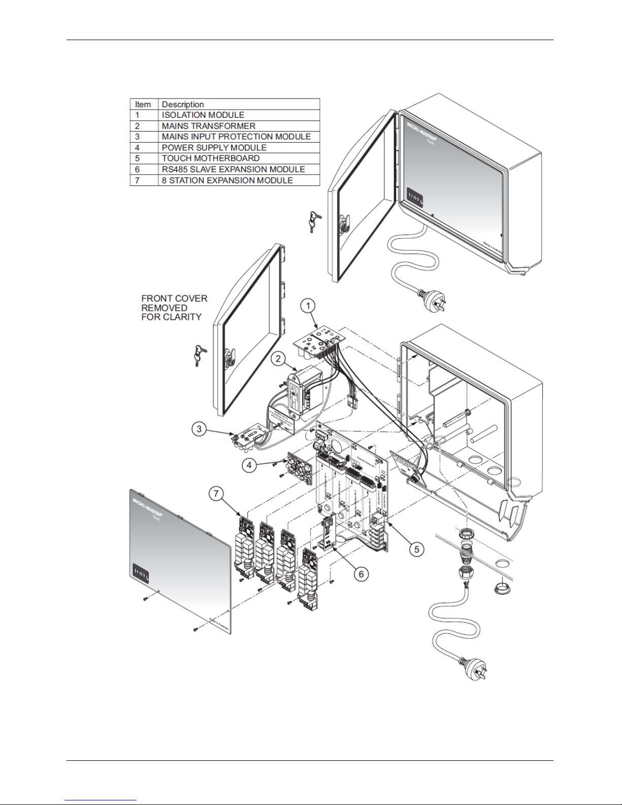
The diagram below shows the breakdown of a Micro-Master Touch Remote Unit.
Figure 3 - Micro-Master Touch Remote Unit - Exploded Diagram
Page 15
Micro-Master Touch User Guide
7
© 2014 Toro Australia Pty Ltd Ver 1.2, June 2014
4 Installation Instructions
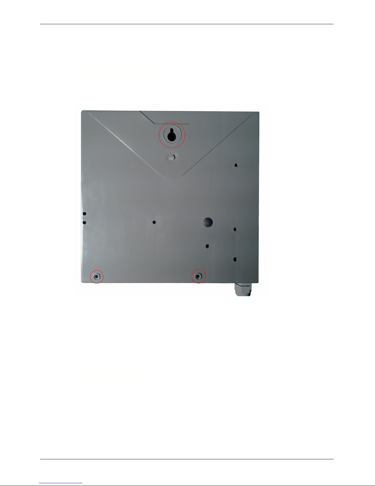
4.1 Wall Mount Installation
On the back of the controller is a “keyhole” shaped mounting slot as well as 2 mounting holes along
the bottom edge. These mounting holes are shown circled red in the next picture. Access to the 2
mounting holes is from the front behind the bottom cover plate.
Figure 4 - Back of Micro-Master Touch Controller
When attaching to wall studs use a No. 10 self tapping screw and leave approx. 6mm of the head
exposed to slip into the “keyhole” slot. To secure and stabilise the controller, drive additional screws
through the bottom mounting holes.
NOTE: When mounting the controller to a sheet metal wall, it is essential to mount timber mounts to
the wall first and then mount the controller to the timber. This prevents high temperatures being
conducted to the controller.
4.2
Module Installation
The Touch controller uses various modules installed into "slots" on both the motherboard and
processor boards to increase its versatility or capacity.
A wide range of modules are available for both the communication slots on the processor board and
expansion slots on the motherboard. Both employ a similar method of mounting and are easy to
install or remove.
Page 16

Micro-Master Touch User Guide
8
© 2014 Toro Australia Pty Ltd Ver 1.2, June 2014
NOTE:
Before any installation or removal of a module occurs,
all power to the unit MUST
be removed
, including the backup battery. Never install or remove a module with power
applied. Damage to the module may occur and this is NOT covered by your warranty.
NOTE:
Two screws are used to provide power and to secure the Expansion Modules.
All
screws must be installed
for the Expansion Module to operate correctly.
The motherboard, which is at the bottom of the case, holds all of the field wiring modules, along with
a power supply module and Radio-Master for Touch RMT200 module, if fitted.
The Power module (already fitted) and Expansion Slots number 5, 6 & 7 use screws to hold the
module in place and are connected to the controller via 8 pins.
Expansion slots 1 to 4 are for the Station(Valve) relay modules, Analogue Input and Digital Input
modules. Each of these modules is connected to the controller by a 20 way edge connector and held
in place by 2 screws. The screw connection points supply 24V AC and GND to the modules, for the
field wiring. Installing a module in slots 1 to 4 is achieved by inserting the tongue of the expansion
module into the edge connector until the 2 screw holes align and then fitting the screws.
The tongue of the module is the slightly smaller end that has stripes down the edge, on both the top
and bottom sides.
Expansion modules 5 & 6 are fitted on edge. Ensure that all the gold pins enter the header connector
on the module and the screw mount aligns with the bracket, then insert the screw. Typically, this is
where the RS485 modules would reside, when other remote units are connected using wire.
Expansion module 7 requires the pins to come through the board into the header and 4 screws to
hold the module in place.
Remember, no power should be present when installing or removing modules. You may also find a
magnetic screw driver of help when trying to install or remove screws.
The processor (or logic) board is the top board in the controller with the LCD screen attached. This
board has 2 slots on the right hand side for various types of communication modules to be installed.
These modules are shorter than the motherboard expansion modules and should never be
interchanged. The connection of the module is achieved by an edge connector and a single screw to
hold the module in place. Once again, slide the tongue of the module into the edge connector until
the screw hole aligns and then insert the screw.
When you restart the controller, navigate to the Expansion Module Configuration page and initiate a
scan by clicking the scan button.
The controller will perform a scan to determine what modules are fitted to the unit and update its
configuration.
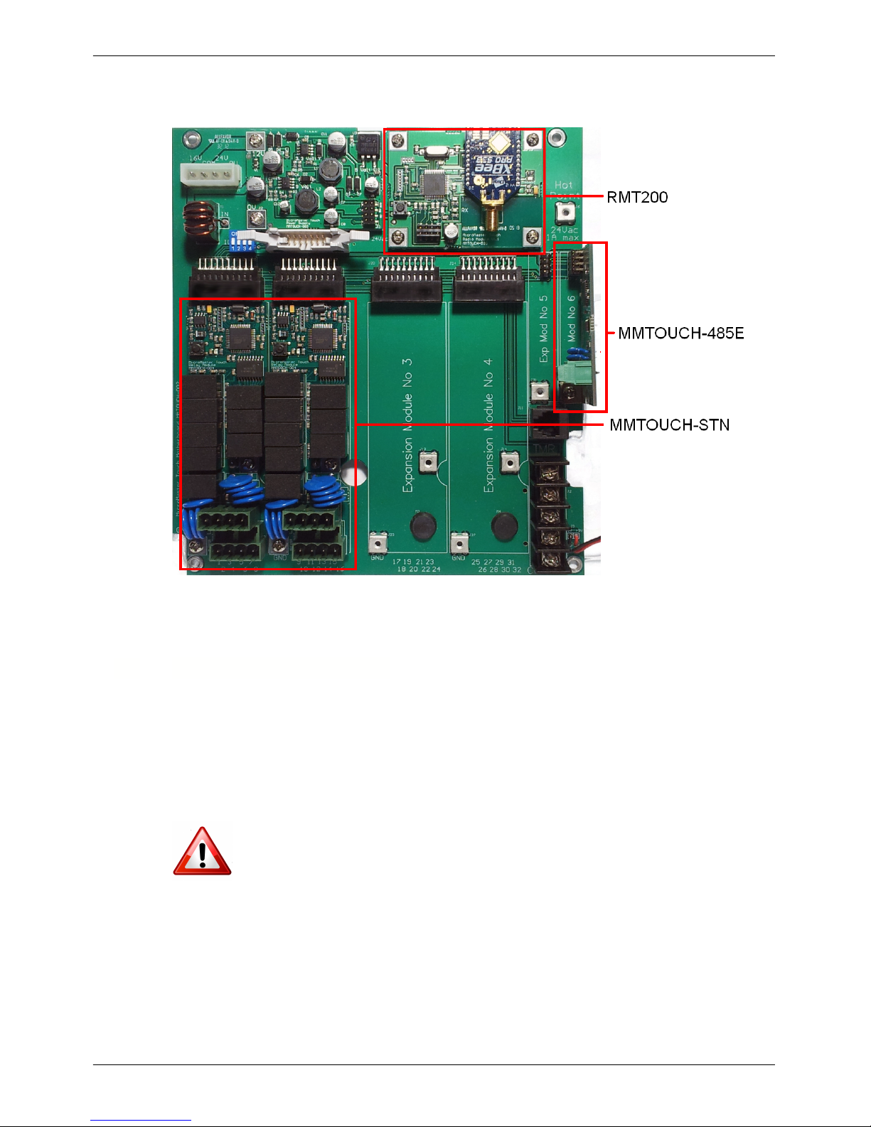
An example of a motherboard is shown in Figure 5. This motherboard has been populated with 2 8
Station Relay Modules (MMTOUCH-STN) in Expansion Module numbers 1 and 2, an RS485 Remote
Expansion Module (MMTOUCH-485E) in Expansion Module number 6 and a Radio-Master for Touch
Page 17
Micro-Master Touch User Guide
9
© 2014 Toro Australia Pty Ltd Ver 1.2, June 2014
Radio Expansion Module (RMT200) in Expansion Module number 7.
Figure 5 - Touch Motherboard with 2 MMTOUCH-STN,
RMT200 and MMTOUCH-485E modules
4.3
Master/Remote selection
The Micro-Master Touch controller can support up to a total of 160 station outputs. This is dependant
on the number of remote units connected and the expansion modules fitted. One Micro-Master
Touch Master Unit can support up to four Touch Remote Units, each fitted with a variety of expansion
modules.
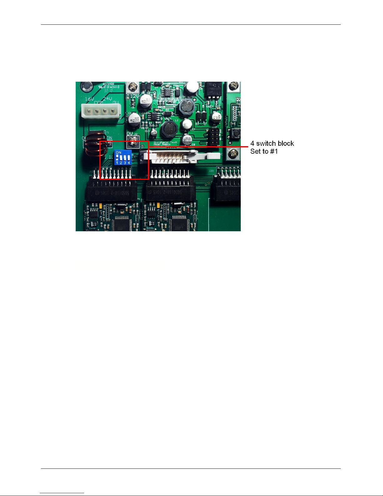
Configuration of a Touch Unit as either a Master Unit or Remote Unit is performed via a four switch
block, numbered 1 to 4, on the motherboard, next to the ribbon cable connector and above
Expansion Module number 1.
When configuring units, all power to the unit MUST be removed, including the backup
battery.
To designate a unit as the Master, all switches on the block should be in the OFF position.
For Remote Unit number 1, the number 1 switch should be ON, all others OFF.
For Remote Unit number 2, the number 2 switch should be ON, all others OFF.
For Remote Unit number 3, the number 3 switch should be ON, all others OFF.
Page 18
Micro-Master Touch User Guide
10
© 2014 Toro Australia Pty Ltd Ver 1.2, June 2014
For Remote Unit number 4, the number 4 switch should be ON, all others OFF.
There can only be one Master controller and one of each of the remotes connected as a group.
In the example below, a unit has been configured as Remote Unit number 1.
Figure 6 - Master / Remote Selection Switch
4.4
Connecting Valve Wire
1. Remove bottom cover.
2. Route 1 wire from each valve though one of the three holes in the bottom of the
controller case. Insert each lead into the appropriate terminal on the connector.
For ease of wiring the connector heads can be removed if required.
3. The common wire for each valve should be attached to a single “Common” wire.
Connect this Common wire to one of the terminals labeled COMMON.
4. When all valve wires have been connected, ensure that all holes and spaces
between valve wires are sealed with a silicone sealant or similar. This ensures
that insects, ants and vermin cannot enter the controller.
Page 19
Micro-Master Touch User Guide
11
© 2014 Toro Australia Pty Ltd Ver 1.2, June 2014
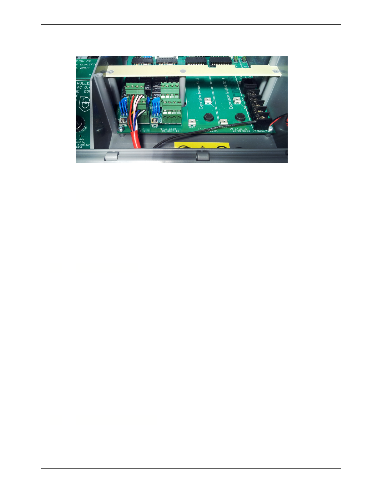
An example of correctly terminated valve wiring is shown below.
Figure 7 - Wiring Terminal Blocks
4.5
Earth Stake
The Micro-Master Touch controllers have a high level of field surge protection (4500 amp 20usec).
For this to work effectively, a good low resistance earth path must be provided to shunt the surges. A
resistance value <10 ohms is acceptable. A resistance value between 10-30 ohms is marginal. A
resistancevalue higher than 30 ohms is not acceptable. In severe lightning areas a 2 metre earth
stake connected to one of the GND terminals can be used ( Use multi-strand 4-6mm wire ).
Ensure soil around the earth stake is kept moist to create a good earth.
4.6
Standby Battery
The Standby Battery is a 9V alkaline MN1604 miniature Battery. This will give several hours of
standby time. The alkaline battery is essential in high temperature conditions as they have a shelf
life of approximately 5 years at 40 degrees Celsius. In the long term, an alkaline battery will be more
reliable and cheaper than an equivalent NiCad battery. They are replaced every 1 to 2 years
depending on the number of power failures in the area.
Note: For extreme conditions with many power failures, a battery holder with (6 AA alkaline cells) will
give an increased Standby time.
NI-Cad (Nickel Cadmium ) batteries should not be used for 2 reasons.
1. For a Ni-cad to be efficient, the operating cycle should be fully charged, then fully discharged.
This is not the case for a Standby battery in an irrigation controller.
2. Poor operation in a high temperature environment. The capacity is only 20% of an alkaline cell
and this is further reduced in high temperature environment.
The 216 standard carbon zinc battery should not be used because of very poor high temperature
performance and low capacity.
4.7
12 Volt DC Operation
The Touch Series controllers can be easily changed to operate on 12VDC. It should only be used
with caution as valves must be fitted locally as wires carrying DC current should not be installed
under ground because of electrolysis. Ideal installation when hydraulic valves are used.
Page 20

Micro-Master Touch User Guide
12
© 2014 Toro Australia Pty Ltd Ver 1.2, June 2014
1. Remove the 4 way connector from the motherboard.
2. Plug in the 12VDC adaptor plug supplied with the controller.
3. Connect the RED lead to +12VDC.
4. Connect the BLACK lead 0VDC.
5. Connect Earth stake as described in the Earth Stake installation instructions.
Page 21

Micro-Master Touch User Guide
13
© 2014 Toro Australia Pty Ltd Ver 1.2, June 2014
5 Controller Setup and Configuration
5.1 Overview
The Micro-Master Touch contains a large number of setup and configuration options.
The various options are described below.
System Setup
The controller setup supports multiple controller ID's within the one installation. To prevent confusion
each controller must be assigned a unique controller identification number. Numbers do not need to
be sequential.
A system wide date/time subsystem keeps track of day and time. The day and time is used to tag
events within the controller.
The controller serial number is a unique factory assigned number.
The controller version displays the current revision of the firmware. The firmware number is in the
form xx,yy,zz. Major revisions ( denoted by xx ) may not be compatible with earlier versions of the
software or hardware. Minor revision numbers ( denoted by yy ) and indicate updated or added
functionality in the firmware. All minor revisions are compatible within a major revision. For
example, minor revision 1.4.z is compatible with revisions 1.0.z through 1.3.z. Minor changes to
controller firmware are denoted by zz.
Changing the firmware is possible by loading a compatible firmware on to a USB flash storage device
and installing the USB device in the front panel USB connector. Selecting the revision in the System
Setup window and clicking the Edit icon will request confirmation. If approved, the controller will
reboot and attempt to update the firmware from the file on the USB device. If a compatible file is not
found, the controller will abort the firmware upgrade and restart.
Global Setup
The controller supports several functions for upgrading, or controller maintenance. The Global Setup
screen supports backup of all controller configuration and totals to a connected USB storage device.
This file can be used to restore the controller to a known state in the event that the front panel needs
to be replaced, or the controller is inadvertently reset.
Options exist to clear the controller totals and logs only, or clear the entire controller configuration to
the factory defaults.
For maintenance purposes the controller has two levels of program control. A Global Enable
prevents all programs from starting. A rain switch enable prevents programs from starting, unless the
program has the Ignore Rain Switch option ticked. By default, all programs obey the rain switch.
It is recommended that after the controller has been installed and configured, a backup of the
controller be performed and the USB backup file stored in a safe location.
Unit Configuration
Each Unit can be assigned a name and individually be enabled or disabled. Each Remote Unit can
be accessed using RS485 or RMT200 expansion modules. Selecting the Comms item and selecting
edit will display a list of available Radio-Master for Touch radio addresses or RS485 addresses.
Selecting the scan option on the radio address screen will search the controller network for all
Radio-Master for Touch or RS485 based modules.
Page 22

Micro-Master Touch User Guide
14
© 2014 Toro Australia Pty Ltd Ver 1.2, June 2014
Expansion Module Configuration
Each expansion module in the Master Unit (except expansion module 1) or a Remote Unit can be
replaced in the field by a Radio-Master for Touch Field Module. The Expansion Module configuration
screen allows selection of the expansion module. Selecting edit will display a list of available
Radio-Master for Touch addresses. Selecting the scan option on the address screen will search the
controller network for all Radio-Master for Touch Field Modules.
Selecting a radio designates the selected field module as a replacement for the expansion module. If
an expansion module has been replaced by a field module, the expansion module in the master or
remote unit becomes inoperable. If an Expansion Module in position 1 is replaced by a field module,
no communication with a Remote Unit will be possible. Hence it is possible to have up to four radio
expansion modules forming a virtual remote unit, without the need for a physical Remote Unit. When
Radio-Master for Touch Field Modules are added to a controller, it is recommended that field
modules remain separate from Remote Units. For example, if an installation has a Master Unit and 1
Remote Unit (Unit 1), then Field Modules should be added as Unit 2/Module 1 etc.
Access PIN Numbers
The controller supports two options for restricting access to levels of functionality in the controller.
Once entered, a valid PIN is active for a user configurable time period. The default time period is 60
minutes. If a PIN is required, the user is directed to the PIN Entry screen.
Limited access allows users to view the status of the various subsystems in the controller, and to
control single station and programs.
Full access allows users access to all areas of the controller. Only users with full access can change
the PIN numbers.
If a PIN number is forgotten, please contact Toro Technical Services for assistance.
Communication Options
The controller supports a number of communication options for connection to outside computing
resources. These options are USB, RS232, RS485, Ethernet, WiFi, and GPRS/GSM/Analogue
Modems.
Depending on the communication module option installed will determine the parameters available for
configuration.
The Ethernet and WiFi communication modules support DHCP address resolution. The WiFi module
supports WPA, WEP, and WPA2 encryption.
Diagnostics
The Micro-Master Touch controller contains a variety of diagnostic tools, for isolating faults in the
front panel. The ability to produce a log file on an attached USB flash storage device can provide
important information regarding the current operation of the controller.
Page 23
Micro-Master Touch User Guide
15
© 2014 Toro Australia Pty Ltd Ver 1.2, June 2014
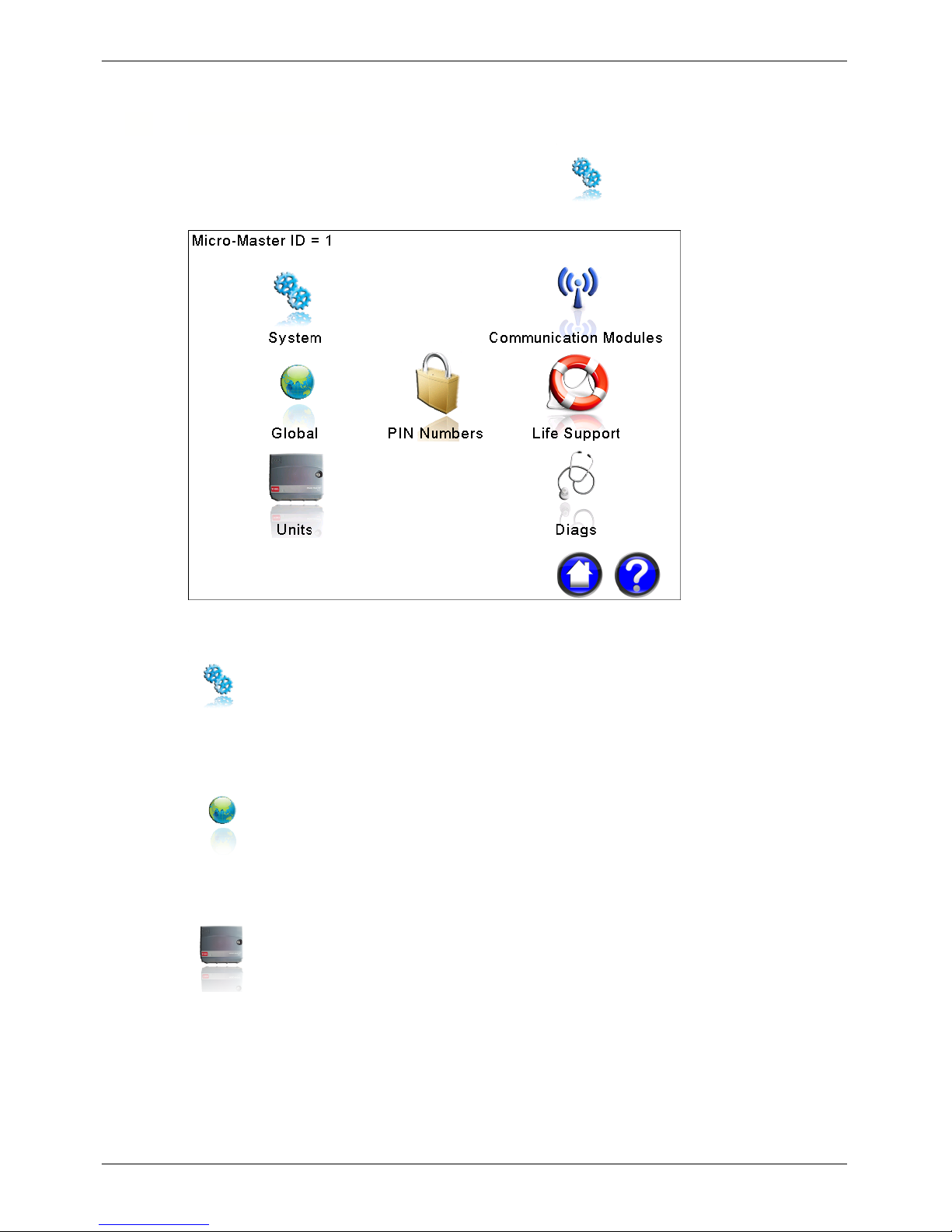
5.2
Setup Selection
The Setup Selection screen is displayed by pressing the icon on the Home Screen.
Figure 8 - Setup Selection Screen
System Setup and Configuration
Pressing this icon displays the System Setup screen to allow edit and control of the Controller ID,
System Date and Time and allow in-field upgrade of the controller firmware.
Global Setup and Configuration
Pressing this icon displays the Global Setup screen to allow reset of the controller memories, and for
setting controller global enable/disable control.
Unit Setup and Configuration
Pressing this icon displays the Unit Setup screen to allow configuration of Units and Expansion
Modules.
Page 24
Micro-Master Touch User Guide
16
© 2014 Toro Australia Pty Ltd Ver 1.2, June 2014
PIN number lock
Pressing this icon displays the PIN Number Setup screen to allow configuration of the controller PIN
security.
Communication Modules
Pressing this icon displays the Communication Module Status screen to show the communication
status and allow modification of available controller communication module options.
Life Support Setup and Configuration
Pressing this icon displays the Life Support Setup screen to allow edit and control of the Life Support
features of the Controller. Life Support provides two levels of limited controller functionality in the
event that the main control panel is inoperable.
Diagnostic Setup and Configuration
Pressing this icon displays the Diagnostics screen to allow diagnostic testing of the controller front
panel.
Help
Pressing this icon displays a help screen explaining the options available.
Page 25
Micro-Master Touch User Guide
17
© 2014 Toro Australia Pty Ltd Ver 1.2, June 2014
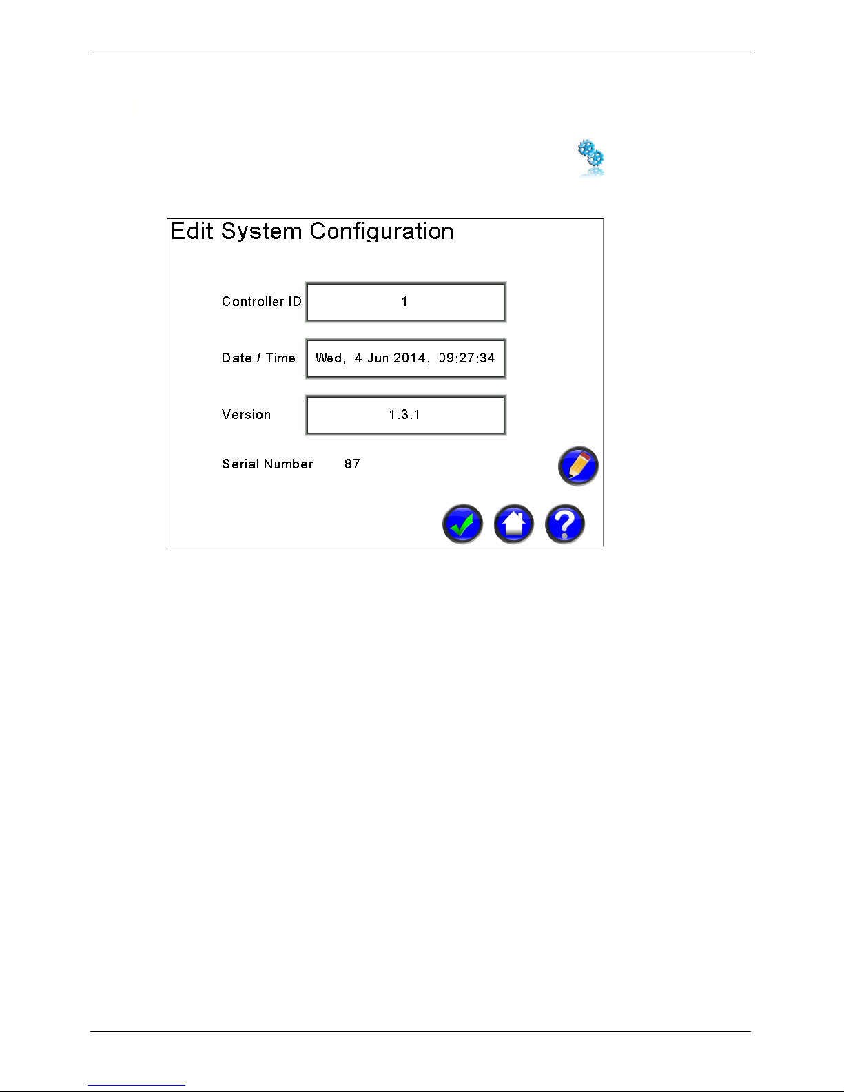
5.3
System Setup and Upgrade
The System Configuration Setup screen is displayed by pressing the icon on the Setup
Selection screen.
Figure 9 - System Configuration
Controller Identification Number
Clicking on the Controller ID will select the item, changing the background to light blue. Selecting the
Controller ID then clicking Edit will display the Number Edit screen, allowing the controller ID to be
changed.
Date Time
Clicking on the Date and Time will select the item, changing the background to light blue. Selecting
the Date/Time then clicking Edit will display the Time Edit screen, allowing the controller date and
time to be changed.
Version
This item displays the current version number of the controller firmware. Clicking on the version item
will select the item, changing the background to light blue. Selecting version and then clicking Edit
will display a confirmation screen. If confirmed, the controller will reset and update the controller
from an upgrade file on the USB flash storage device if one is present.
The firmware update process does not perform any checks for operating programs or input
conditions. The user must ensure that all controller programs are stopped before attempting a
firmware upgrade.
Page 26
Micro-Master Touch User Guide
18
© 2014 Toro Australia Pty Ltd Ver 1.2, June 2014
Controller Serial Number
The Controller Serial Number is a unique factory assigned number and is not configurable.
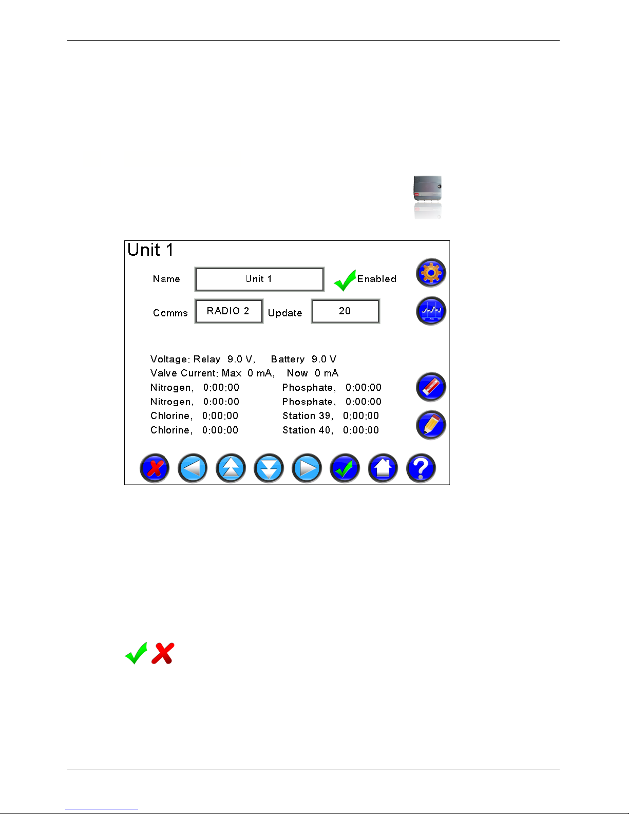
5.4
Unit Configuration
The Unit Configuration Setup screen is displayed by pressing the icon on the Setup
Selection screen.
Figure 10 - Controller Unit Configuration
In the example screen shown in Figure 10, Remote Unit 1 has the default name of Unit 1, and is
connected to the network using Radio Module number 2. The status for the unit is updated every 20
seconds, and the current runtime status is shown. The status shown is dependant on the type of
modules in the remote unit. For analogue sensors, the current value of the sensor is shown, and for
digital modules, the open/closed status is shown.
Unit Name
Each Unit can be assigned a name. Names are limited to 20 characters. Selecting the name button
and clicking Edit will display the Text Edit screen.
Unit Enabled
Remote Units can be enabled or disabled. Disabling an Remote Unit prevents stations on that
Remote Unit from being operated for example, to allow maintenance to occur. Clicking on the tick
(cross) will change the Unit to disabled (enabled).
Page 27
Micro-Master Touch User Guide
19
© 2014 Toro Australia Pty Ltd Ver 1.2, June 2014
Unit Update Rate
Clicking on the update item will select the item, changing the background of the selected item to light
blue. Selecting the update item and clicking Edit will display the Number Edit screen.
The Unit Update Rate is the number of seconds between updates and defines how often the Master
Unit communicates with Remote Units to gather status information. Changing the Unit Update Rate
to a shorter time means the status of units is checked more often. Care should be taken to not set
this rate too low, as it could delay the operation of stations being turned on or off. A value of 10
seconds is considered an absolute minimum without severely impacting station operations.
Unit Module Status
This area displays the current status of the unit expansion modules.
Unit Communication Method
Clicking on the Comms item will select the item, changing the background of the selected item to
light blue. Selecting an item and then clicking Edit will display the Control Select screen to allow
selection of available communication devices.
5.5 Expansion Module Configuration
The Unit Expansion Module Configuration screen is displayed by pressing the icon on the Unit
Configuration screen.
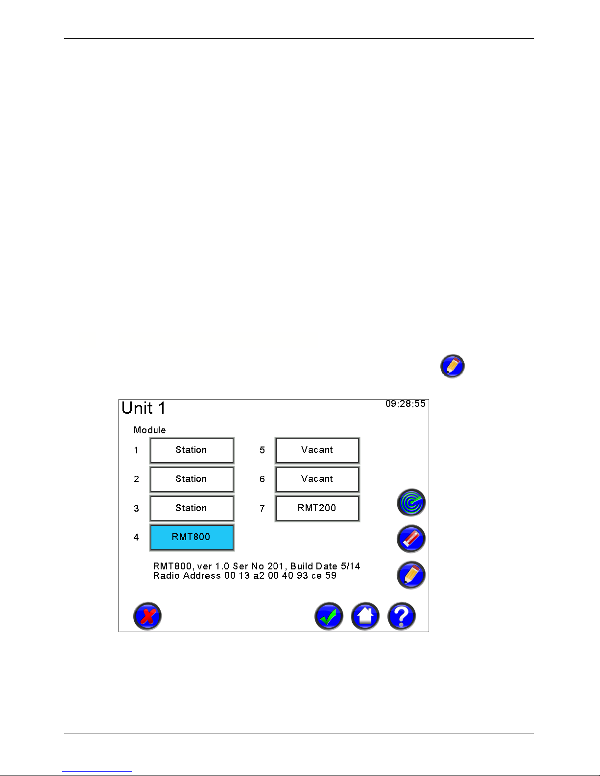
Figure 11 - Controller Expansion Module Configuration
In the example screen shown above, Expansion Module 4 in the Remote Unit 1 has been replaced by
a Radio-Master for Touch RMT800 Field Module with radio address 00 13 a2 00 40 93 ce 59. The
module is version 1.0, serial number 201 and was manufactured in May 2014.
Page 28

Micro-Master Touch User Guide
20
© 2014 Toro Australia Pty Ltd Ver 1.2, June 2014
Module Identification and Version
Clicking on the Expansion Module will select the item, changing the background to light blue. It will
also show the build date, serial number and communication method for the selected expansion
module.
Scan Expansion Modules
This icon will cause a scan of the selected Remote Unit to determine the current configuration of
each expansion module in the Remote Unit.
Page 29
Micro-Master Touch User Guide
21
© 2014 Toro Australia Pty Ltd Ver 1.2, June 2014
5.6
Radio-Master for Touch Field Modules
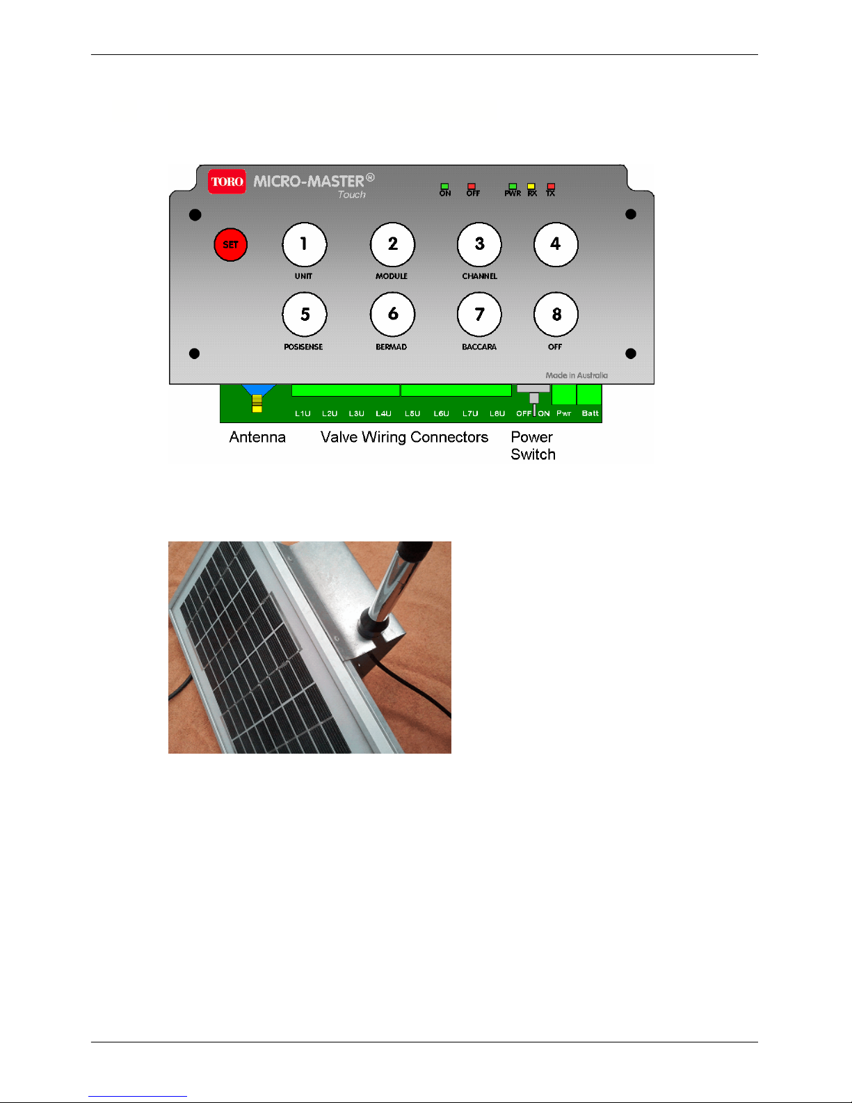
RMT Field Module Installation
Figure 12 - RMT800 Panel with connector positions
Aerial Installation
Figure 13 - Aerial mounted on Solar Panel
Note: Depending on the particular installation environment it may be easier to install the antenna
prior to mounting the Solar Panel assembly onto the mast. Remember, the higher the antenna, the
better the coverage.
Loosen the nut on the base of the antenna and slide the antenna into the slot located on the top edge
of the Solar Panel Mounting Plate.
Retighten the nut on the base of the antenna.
Solar Panel Mounting Bracket Installation
The Solar Panel Mounting Plate has been designed to maximise the average available solar power
whilst reducing wind resistance and providing ease of assembly. The angle of the Solar Panel has
Page 30

Micro-Master Touch User Guide
22
© 2014 Toro Australia Pty Ltd Ver 1.2, June 2014
been optimised for locations near the latitude of Sydney, Adelaide, and Perth, but will provide good
operation over most of Australia.
The Solar Panel Mounting Plate kit is supplied with 4 saddle clamps. Both 2” (50mm) and 1” (25mm)
water pipe saddle clamps are supplied to allow several mounting options. Only two saddle clamps
are required to mount the Solar Panel Mounting Plate.
Attach the Solar Panel Mounting plate to the mast using two saddle clamps and 3/16” bolts and nuts.
Orientate the Solar Panel Mounting Plate so that the dark face of the Solar Panel is facing the
direction of the midday sun. This is approximately North and maximises the Solar Panel output.
Tighten the 3/16” nuts.
Route the Solar Panel power cable and antenna cable to the RMT Field Module. Secure the cables
using cable ties or other appropriate means.
RMT Field Module Installation
NOTE: It is important for the correct and continued reliable operation of the RMT Field Modules that
cables and wires are not subjected to deformation or damage during installation or normal use.
During installation, ensure that cables and wires are not positioned or routed such that deformation of
cables or wires could occur. Routing of the antenna cable should not result in a bend radius of less
than 75mm.
Using appropriate fasteners, attach the RM106 Module Mounting Plate in the desired position using
the two ¼” holes located at the top and bottom of the Module Mounting Plate. Using the 3/16” bolts
and nuts attach the RMT Field Module to the Module Mounting Plate and tighten.
Remove the front cover of the Radio-Master for Touch Field Module.
Connect the antenna cable by passing the gold coloured cable connector through the left hand cable
gland on the bottom of the RMT Field Module. Route the antenna cable such that a Rain drip loop is
formed. The apex of the loop should hang below the bottom edge of the RMT Field Module case.
Take the antenna cable connector and gently screw it onto the gold antenna connection protruding
from under the keyboard panel. Ensuring that the cable is not under stress tighten the gland to
exclude water and pests. Damage caused by water and pests (ants, slugs, mice, etc.) is not covered
under your warranty.
Connecting the Solar Panel Cable
Loosen the right hand cable gland nut and insert the Solar Panel power wires.
Strip 5mm of insulation from the Solar Panel wires.
Connect the red Solar Panel wire to the Connector Block Pwr position labelled”+” and connect the
blue or black Solar Panel wire to the Connector Block Pwr position labelled “-“.
Tighten the cable gland nut.
Connecting the Battery Cable
The battery connector which was unplugged for shipment should now be connected to the Batt
position on the right hand side of the RMT Field Module board, next to the Pwr connector. This must
be done in order for the unit to function correctly.
Powering the RMT Field Module from a RM101 Plug Pack
Ensure the RM101 Plug Pack is not plugged into the 240V mains wall socket. Remove the connector
from the cable by cutting the 2.1mm plug from the RM101 Plug Pack cable.
Page 31

Micro-Master Touch User Guide
23
© 2014 Toro Australia Pty Ltd Ver 1.2, June 2014
Loosen the right hand cable gland nut and insert the plug pack wires.
Separate the plug pack wire into the two conductors and strip 5mm of insulation from each wire.
Connect the wire with the white stripe to the Connector Block Pwr position labelled ”+” and connect
the other wire to the Connector Block Pwr position labelled “-“.
Plug the RM01 Plug Pack into a 240V mains wall socket and switch on. Using a voltmeter on at least
a 20V DC range, confirm that a nominal 12Vdc is present across the Connector Block Pwr position.
Tighten the cable gland nut.
Connecting Valve Wire, All Radio-Master for Touch Modules
The RMT Field Module is designed for 2 wire solenoid operation; 12V is momentarily applied across
the connector block positions labelled “L” and “U” for each valve when commanded on or off by a
Micro-Master Touch controller.
Loosen an appropriate cable gland nut and insert the solenoid wires.
Strip 5mm of insulation from the solenoid wires.
Connect the solenoid latch wire to the Connector Block positions marked “L” for the appropriate valve
number. For a Bermad S985 solenoid the Latch Wire is White. For a Baccara 2 wire latching solenoid
the Latch wire is Green.
Connect the solenoid unlatch wire to the Connector Block positions marked “U” for the appropriate
valve number as shown in the previous picture. For a Bermad S985 solenoid the Unlatch Wire is
Red. The Black wire is unused. For a Baccara 2 wire latching solenoid the Unlatch wire is Black.
Tighten the cable gland nut.
To prevent insect infestation, any gaps should be eliminated, by tightening the cable glands securely,
or filling the gaps with a suitable all weather sealant.
Connecting Digital Sensors, RMT440D Field Modules
The RMT440D is designed to accept four digital pulse sensors. The RMT440D inputs accept voltage
free contact closures. The sensor wiring positions are on the left hand side connectors and marked 1
to 4 with + and – positions. The – position goes to ground, and the + position to the sensor output as
shown in Figure 14.
RMT440D Inputs
1 2 3 4
+ - + - + - + -
Figure 14 - RMT440D Connection Schematic
Page 32

Micro-Master Touch User Guide
24
© 2014 Toro Australia Pty Ltd Ver 1.2, June 2014
Connecting Analogue Sensors, RMT440A Field Modules
The RMT440A is designed to accept four 4-20mA Analogue sensors. The sensor wiring positions are
on the left hand side connectors and marked 1 to 4 with + and – positions. The RMT440A supplies
24VDC to the + terminal to power sensors. A typical sensor connection is shown in Figure 15. Refer
to the sensor manufacturers manual for correct connection of the sensor.
GND
+
O/P
GND
+
O/P
GND
+
O/P
GND
+
O/P
RMT440A Inputs
1 2 3 4
+ - + - + - + -
Figure 15 - RMT440A Connection Schematic
Interfacing the RMT Field Module module with a Micro-Master Touch
Master
The Valve outputs of each RMT Field Module are numbered 1 to 8. Each RMT Field Module module
will replace 1 Expansion Module from slot 2 to 4 in the Master unit, or, any or all Expansion Modules
in a Remote Unit. This means that you can have a mix of a Master, Remotes and RMT Field Module’
s, or a Master and all RMT Field Module’s. This allows maximum flexibility when designing and using
the system. The only condition is that slot 1 in the Master must always be a Station Module.
The radio system in the Touch controllers allows use on up to 8 separate channels. By default, the
radio channel is set to channel 1. If multiple Touch systems have been installed in the surrounding
area it may be necessary to select another channel. The channel of the Master Unit dictates the
channel to be used in the RMT Field Modules. If the channel is set to 2 in the Master, then the
channel must be set to 2 in all Remote Units and RMT Field Modules that you wish to use with that
Master Unit. This only needs to be done if you are not going to use the default settings.
Once setup and turned on, the RMT Field Module will automatically announce and configure itself in
to the Touch Master Unit.
Resetting the Module back to Factory settings
Resetting the module back to the factory settings can be achieved easily. Ensure that the unit is
turned off. Press and hold the SET key then turn the unit on. This will reset the module to Channel =
1, PosiSense = off, Unit = 0, Module = 0. All LEDs will flash 3 times.
Setting the Channel Number
By default, the channel number is set to 1. Figure 12 shows the front panel of the RMT Field Module.
It can be seen that many of the keys have multiple functions.
To set a new channel number, ensure that the unit is turned on, then, in order, one button at a time,
press SET, CHANNEL and the number of the new channel to use (1 to 8). You will have 5 seconds
Page 33

Micro-Master Touch User Guide
25
© 2014 Toro Australia Pty Ltd Ver 1.2, June 2014
between each key press. If you take longer than 5 seconds between each key the command
sequence will abort and no change will be effected. Once entered correctly the module will flash the
ON LED 3 times.
Setting the Unit Number and Expansion Module Slot Number
The RMT Field Module is capable of being a member of the Master Unit (Expansion Modules 2-4) or
any Remote Unit ( Expansion Modules 1 to 4). Use the guide below to set the relevant unit and
module ID.
To join the Master Unit press, SET, UNIT, SET. ie. press SET followed by UNIT(1) followed by SET.
The ON LED will flash 3 times.
To be part of Remote Unit 1 press, SET, UNIT, 1.
To be part of Remote Unit 2 press, SET, UNIT, 2.
To be part of Remote Unit 3 press, SET, UNIT, 3.
To be part of Remote Unit 4 press, SET, UNIT, 4.
Then select the Expansion Module position this module is to occupy by pressing, SET, MODULE,
followed by 1, 2, 3, or 4. The ON LED will flash 3 times.
Remember only 2 to 4 is valid for the Master Unit and ensure the module position is vacant, as a
RMT Field Module will take priority over an installed expansion module.
Setting PosiSense
The RMT Field Module is capable of supporting non-PosiSense and PosiSense solenoids in any mix
across the valve positions. Setting PosiSense is achieved in a similar manner as described above.
The ON LED will flash 3 times on a successful command.
For example, pressing SET, PosiSense, BERMAD, 2 will set output 2 as a Bermad solenoid.
Pressing SET, PosiSense, BACCARA, 7 will set output 7 as a Baccara solenoid.
Pressing SET, PosiSense, OFF, 1 will turn off PosiSense on output 1. PosiSense should be turned
off if an RM401 Pump Start Relay is connected to the output.
Any option selected without an output number at the end will have the effect of a blanket change on
all outputs.
For example, pressing SET, PosiSense, BERMAD (with no number keyed for 5 seconds), will set all
outputs for a Bermad solenoid.
Pressing SET, PosiSense, OFF (with no number keyed for 5 seconds) wil turn PosiSense OFF for all
outputs.
LED Indicators
The RMT Field Module has 5 LED lights across the right hand top of the keyboard panel. These are
marked as ON, OFF, PWR, RX & TX and behave as follows:
ON – flashes when a valve is turned on by pressing a valve key on the keyboard.
It is also used to show the valid entry of a setup command via the keyboard.
OFF – flashes when a valve is turned off by pressing a valve key on the keyboard.
PWR – Shows power to the module and the state of the radio connection. A solid ON or OFF
indicates a power issue, or a radio issue with the radio being unable to join the radio network. A
Page 34

Micro-Master Touch User Guide
26
© 2014 Toro Australia Pty Ltd Ver 1.2, June 2014
double flash approximately every 5 seconds indicates a successful network connection.
RX – flashes when data is received by the module.
TX – flashes when data is transmitted by the module.
Turning Valves On & OFF manually
To turn a valve ON & OFF press the relevant button numbered 1 to 8 on the keyboard. When the key
is pressed the ON LED will flash to show the valve is turning on, or, the OFF LED will flash is the
valve is being turned off. Repeated pressing of the selected valve will turn the valve on and off.
5.7
Communication Module Options
The Communication Option screens are displayed by pressing the icon on the Setup
Selection screen.
Figure 16 - Communication Module Parameters
Page 35

Micro-Master Touch User Guide
27
© 2014 Toro Australia Pty Ltd Ver 1.2, June 2014
Figure 17 - Communication Module Configuration Parameters
In the example screen shown above, an ethernet communication module has been installed in
position 2, and has been assigned an IP address of 192.168.1.10 by a DHCP server on address
192.168.1.1
Communication Module Selection
Clicking on a Communication Module item will select the item, changing the background of the item
to light blue. Selecting the button and then clicking Edit will display an appropriate screen to allow
modification of available communication parameters for the selected communication module.
Communication Module Status
This area displays the current status for the communication modules.
Communication Module Parameters
This area displays available communication module parameters. The type of parameters available
depends on the selected communication module. Clicking on an item will select the item, changing
the background of the item to light blue. Selecting the button and then clicking Edit will display an
appropriate screen to allow modification of the selected communication parameter.
Page 36

Micro-Master Touch User Guide
28
© 2014 Toro Australia Pty Ltd Ver 1.2, June 2014
5.8
PIN Number Setup
The PIN Number Setup screen is displayed by pressing the icon on the Setup Selection
screen.
Figure 18 - PIN Number Setup
Limited Access PIN
Clicking on the Limited Access PIN item will select the item, changing the background of the item to
light blue. Selecting the button and then clicking Edit will display the Number Edit screen.
Full Access PIN
Clicking on the Full Access item will select the item, changing the background of the item to light
blue. Selecting the button and then clicking Edit will display the Number Edit screen.
PIN Timeout
Clicking on the PIN Timeout item will select the item, changing the background of the item to light
blue. Selecting the button and then clicking Edit will display the Number Edit screen.
Lost PIN
If a Full Access PIN number is forgotten, no access to any function is possible. Please contact Toro
Technical Services for assistance.
5.9
Commissioning Table
Use the Commissioning Sheet (Table 1) on the next page to fill in commissioning data for later
reference.
Print 1 sheet for each Unit.
Page 37

Micro-Master Touch User Guide
29
© 2014 Toro Australia Pty Ltd Ver 1.2, June 2014
Micro-Master Touch Controller Output Commissioning Sheet
Unit No.
Station
Number
Valve Location
Valve
Current
Wire Colour /
Radio
Address
Comments
1
2
3
4
5
6
7
8
9
10
11
12
13
14
15
16
17
18
19
20
21
22
23
24
25
26
27
28
29
30
31
32
Table 1 - Output Commissioning Sheet
Page 38

Micro-Master Touch User Guide
30
© 2014 Toro Australia Pty Ltd Ver 1.2, June 2014
5.10
Global Setup
The Global Setup screen is displayed by pressing the icon on the Setup Selection screen.
Figure 19 - Global System Configuration
Reset Controller
Clicking on Reset Controller will select the item, changing the background to light blue. Selecting
Reset Controller and then clicking Edit will display a confirmation screen. If confirmed, the controller
will reset the controller to the factory default condition.
Reset Totals / Logs
Clicking on Reset Total / Logs will select the item, changing the background to light blue. Selecting
Reset Totals / Logs and then clicking Edit will display a confirmation screen. If confirmed, the
controller will reset the controller totals and logs to zero. This option does not erase the configuration
of programs, sensors etc.
Backup Controller
Clicking on Backup Controller will select the item, changing the background to light blue. Selecting
Backup Controller and then clicking Edit will display a confirmation screen. If confirmed, and a USB
flash storage device is connected, the controller will backup the controller configuration and totals to
the USB flash storage device.
Restore Controller
Clicking on Restore Controller will select the item, changing the background to light blue. Selecting
Restore Controller and then clicking Edit will display a confirmation screen. If confirmed, and a USB
flash storage device with a valid backup file is connected, the controller will restore the controller to a
previously saved controller configuration.
Page 39

Micro-Master Touch User Guide
31
© 2014 Toro Australia Pty Ltd Ver 1.2, June 2014
Global Program Enable
A tick indicates that all controller programs are able to start. A cross indicates that all controller
programs will not start. Clicking the tick (cross) will disable (enable) the programs.
Rain Switch
A tick indicates that the controller is in a rain switch condition. Only programs that have been
configured to Ignore Rain Switch will start. Clicking the tick (cross) will disable (enable) the
programs.
Page 40

Micro-Master Touch User Guide
32
© 2014 Toro Australia Pty Ltd Ver 1.2, June 2014
6 Micro-Master Touch Screen Introduction
Each screen in the Micro-Master Touch controller has been designed to follow a common layout
whenever possible. This serves to simplify the familiarity process and greatly ease the operation of
the controller.
Generally, from the Home Screen, each major function area shows a list of eight function entries, eg
a list of programs, list of pumps etc. If there are more than eight entries in the function area, a row of
four navigation buttons along the bottom of the screen allows access to the next list of eight entries.
When necessary, the labels of the four buttons changes to allow access to further entries.
The right hand side of the screen contains action buttons. Depending on the function area, these
buttons will initiate commands on the selected entry, or allow access to the editing functions for the
selected entry.
On the edit screens, buttons in the navigation area allow the user to accept, or cancel any changes to
the function parameters, or navigate to the next entry in the function. A home button returns the user
directly to the main menu, without saving any changes to the function. A help button shows
information relating to the function.
On the right hand of the edit screen, a number of action buttons allow further modification of the
functions parameters. As far as possible, these buttons will have similar affects on each screen they
are displayed.
For example, consider the Pump Set Edit Screen as shown in Figure 20, where the Action,
Navigation, and Function Parameter areas are shown.
Figure 20 - Touch Screen Layout
In the Action Area, icons represent various actions that will be applicable for the currently displayed
function. Not all icons will be displayed for all functions.
The advanced parameter edit button will display more advanced parameters, including
parameters that are unlikely to change frequently, and status and totaliser data for the function.
The log button displays a graphical log of parameters appropriate to the function. In most
cases, this will be a graph of the associated flow meter.
Page 41

Micro-Master Touch User Guide
33
© 2014 Toro Australia Pty Ltd Ver 1.2, June 2014
The copy button prompts the user for a number using the number edit screen, and if accepted,
copies the current function parameters into the new function subsystem. This allows users to copy
complete function setups from one function to another. An example of this includes a number of
programs that are identical except for different water budgets or prestart delays.
The delete/erase button erases the selected function parameters to factory defined default
values. If this button is clicked when the name parameter is selected, the user is prompted to confirm
the reset of all function parameters to factory defined default values.
The edit button edits the selected function set or parameter depending on the type of page
displayed. The screen displayed depends on the type of parameter to be changed.
In the Navigation Area, icons represent actions to move between function sets, or between pages of
information for the current function set.
The accept button accepts changes to the function set and returns the screen to the function
set list. This button must be pressed to save any changes the function configuration. If the screen
timeout occurs before the accept button is pressed, all current modifications will be lost.
The cancel button cancels all changes, including changes in the advanced edit screens, and
returns the screen to the function set list.
The home button cancels any changes to the function set and displays the Home Screen.
The help button shows the help screen, containing appropriate help information for the
currently displayed screen.
Clicking a page selection button will display the eight function sets listed under the button. This
type of button is used when lists of function sets are displayed. If there are more than 32 function
sets for the function, clicking the first or last page selection button will change the function sets listed
under the buttons.
The and buttons are used when editing a function set. Clicking one of the buttons will
accept any changes to the function set and displays the previous or next function set. In the
advanced parameters edit screens, clicking these buttons show the previous and next advanced
parameters edit screens.
The and buttons displays more information for the current function set. For example,
when editing a program, clicking this button will display the previous or next 4 groups. The display
wraps at the start and end of the groups, hence if the first 4 groups are displayed, clicking this button
will display the last 4 groups.
Page 42

Micro-Master Touch User Guide
34
© 2014 Toro Australia Pty Ltd Ver 1.2, June 2014
The navigation is shown graphically in the following diagram, using the Pump Set subsystem as an
example.
Home Screen
ÛÛ
Ü
Pump Set List
ÛÛ
Ü
Previous Pump Set Pump Set Edit Next Pump Set
ÛÛ
Ü
Previous Advanced Pump
Parameters pages for the current
Pump Set
Advanced Pump
Parameters
Next Advanced Pump Parameters
page for the current Pump Set
Page 43

Micro-Master Touch User Guide
35
© 2014 Toro Australia Pty Ltd Ver 1.2, June 2014
7 Home Screen
The Main Screen is shown at startup. The display will return to this screen after 60 seconds of
inactivity on any other screen.
After 60 seconds of no selection being made on this screen, the screen will be blanked to conserve
power and extend the LCD lifespan. If the screen is blanked, pressing anywhere on the screen for 2
seconds and releasing will reactivate the screen and display this Home Screen.
Each major function of the controller is accessed from this menu.
Figure 21 - Home Screen
Programs
Pressing this icon displays the programs list to edit and control programs.
Stations
Pressing this icon displays the stations list to edit and control stations.
Pumps
Pressing this icon displays the pump set list to edit and control pump sets.
Page 44

Micro-Master Touch User Guide
36
© 2014 Toro Australia Pty Ltd Ver 1.2, June 2014
Filters
Pressing this icon displays the filter bank list to edit and control filter banks.
Chemical
Pressing this icon displays the chemical list to edit and control chemicals.
Sensors
Pressing this icon displays the sensors list to edit and control sensors.
Manual
Pressing this icon displays the manual control screen.
Reports
Pressing this icon displays the reports screen.
Setup
Pressing this icon displays the setup selection screen.
Help
Pressing this icon displays a help screen explaining the options available from the Home Screen.
Irrigation Status
Pressing this icon displays the current status of running programs and other controller subsystems.
Page 45

Micro-Master Touch User Guide
37
© 2014 Toro Australia Pty Ltd Ver 1.2, June 2014
8 Status Screen
The Status Screen is displayed by pressing the icon on the Home Screen.
The Status Screen shows the current status of controller programs and subsystems and updates
every 5 seconds.
If there are any programs currently running, the status screen displays the current shift, and the time
remaining for the shift. The status screen displays a list of programs that are scheduled to start. This
list shows the earliest scheduled program first. The status screen also displays active inputs, outputs,
filters, and chemicals.
A number of lines are provided in each section. The lines will scroll if there are more lines to be
displayed.
For example, if there are 10 active programs, the lines will scroll up every 5 seconds to show the next
active program.
Figure 22 - Status Screen
In the example screen shown above, the Treelot Irrigation program is active and is irrigating group1,
with 1minute 59 seconds remaining. The Chlorine chemical associated with group 1 is active and has
53 seconds remaining. The filter pressure differential switch input is closed, and Filter Bank 1 is
active.
The 'Next Programs to Start' list show that the Circulation program will commence on Saturday at
1:00am
Page 46

Micro-Master Touch User Guide
38
© 2014 Toro Australia Pty Ltd Ver 1.2, June 2014
9 Multi Station Programs
9.1 Overview and Operation
The Micro-Master Touch controller supports 32 independent multi-station programs. All programs
operate independently of each other, hence programs can operate concurrently or overlapped if
required. Overlapping programs allows programs to control different areas or to perform different
functionality without affecting other programs. For example, one program can be used for irrigation,
whilst another program might be controlling security lights.
Irrigation Programs can be set up in two different modes
1. Sequential Irrigation
2. Group Irrigation.
Program Operation
When the Micro-Master Touch controller is powered on, all enabled programs are in the Idle state.
When a program is due to start according to the Day Table and Start Times, or the Start Control Input
is closed, the program will decide whether to execute a Prestart Delay or continue to Starting. If a
PreStart Delay has been set, the program starts the Pump Set, then counts down the set PreStart
Delay. At the conclusion of the delay, the program starts the first group in the program. If an
InterStation Delay has been set, the delay is inserted between each station in the group. The
program then moves to the Active state.
In the Active state, the program counts down the runtime, while monitoring the Control Sensor Inputs.
If a Control Sensor input becomes valid, the appropriate action is executed. When the group runtime
expires, the program determines the next valid group and moves to the Change Group state. The
program attempts to maintain a consistent number of active stations while changing groups. If there
are no delays, stations on the same Expansion Unit are turned on and off at the same time. If there
is an InterStation Delay, but no Group Delay, the controller will turn off one station in the current
group and turn on one station in the next group, before delaying for the InterStation Delay time. If
there is a Group Delay time set, then all of the stations in the current group are turned off (with an
InterStation Delay, if set), the program delays for the Group Delay time and the stations in the next
group are turned on (with an InterStation Delay if set).
For example. A program has stations 1, 2, 3 in group 1, and stations 3, 4, 5 in group 2, and has an
InterStation Delay, and no Group Delay. When group 1 completes, the controller will turn off station
1 and turn on station 4 at the same time. The controller will then delay for the InterStation Delay
time. Then the controller will turn off station 2 and turn on station 5 at the same time. Station 3
continues to operate through the group change.
When all programmed groups have run, the program stops the pump set, and filter bank. If a Cycle
Delay is set, and more than one cycle is programmed, the program enters the Cycle Delay state. At
the expiration of the Cycle Delay, the program will restart the irrigation, using a PreStart Delay if one
is set.
After all cycles have completed, the program stops the pump set and filter bank, starts the next
program is one has been set, and enters the Idle state, ready to run the process again when required.
The Irrigation Program operation is shown in Figure 23.
Page 47

Micro-Master Touch User Guide
39
© 2014 Toro Australia Pty Ltd Ver 1.2, June 2014
Idle
- wait for
next start time
- monitor control
sensors
PreDelay
- start pump set
Starting
- turn on valves
in first group
- start pump set
- start filter set
Active
- count down
runtime
Change
Group
Holding
- turn off valves
in current group
Unholding
- turn on valves
incurrent group
Stopping
- turn off valves
- stop pump set
- stop filter set
Group
Runtime
expired
Irrigation complete
HOLD
Cycle
Complete
PreStart Delay
> 0
PreStart Delay = 0
InterGroup
Delay
Cycle
Delay
Cycle Delay Complete
and PreStart DElay > 0
more cycles
Irrigation
Held
Cycle Delay
Complete
UNHOLD
Figure 23 - Multi Station Irrigation Program Schematic
Page 48

Micro-Master Touch User Guide
40
© 2014 Toro Australia Pty Ltd Ver 1.2, June 2014
Sequential Programs
Sequential Programs have a runtime allocated to each individual station output. Irrigation will begin
at station 1 and end at the last station programmed. This is a simple way of programming if only one
station at a time is being irrigated. Stations with a runtime of zero are skipped.
Grouping Programs
A Grouping Program can have up to 48 groups of up to 40 stations. Due to electrical limitations only
eight valves per master/remote unit are allowed. Each group has an individual group runtime. Each
group can have up to four chemicals assigned. The same four chemicals are used in all groups of a
program, however the runtime for each chemical in each group can be different.
Any station can be in one or any number of groups. A group may contain no stations. i.e. As a
program delay.
If several pumps are used during a program, the pumps can simply be loaded into the groups with the
stations. When the group of stations is switched on, the pump will be switched on at the same time.
Use Program 1 Config
Each program, by default, shares some configuration parameters with Program 1. These parameters
include modes and units, delays, control sensors, pump sets, filter banks and flow meters. These
parameters are shown with a '*' next to the name on the display during edit functions. Changing a
shared parameter will change the parameter for all programs that have 'Use Program 1 Config'
enabled. When 'Use Program 1 Config' is disabled for a particular program, the shared parameters
are copied from Program 1 to the particular program and then are specific to that program.
In this way the majority of situations will only have to set basic irrigation parameters once.
Complicated and specialised programs can then be individually programmed.
Water Budget
Each program has a water budget. Water budgets can be set from 0% to 250% in increments of 1%.
Enabled Programs and Rain Switch
Each program can be enabled or disabled. In conjunction with program enabling, a global rain switch
is available. A program must be enabled and the global rain switch must be off for the program to
run. An option to force the program to ignore the global rain switch is available in the Advanced
Parameters pages.
Irrigation Units
Group or station runtimes are entered as a number of units. The available units are hours:minutes,
minutes:seconds, or volumetric. If the selected Irrigation Unit is volumetric, the units used for
irrigation are the same as the units of the allocated flow meter.
For example, if flow meter 1 has been set with units of kilolitres, and program 1 irrigation unit is
volumetric and uses flow meter 1, then the values entered for each group of station in program 1 will
be kilolitres.
Injection Units
Units for chemical injection can be either hours:minutes, minutes:seconds, or volumetric. If the
selected Injection Unit is volumetric, the actual units used are the same as the units for the flow
meter allocated to the chemical.
Page 49

Micro-Master Touch User Guide
41
© 2014 Toro Australia Pty Ltd Ver 1.2, June 2014
Next Program
Each program has an option to start another program when the program completes. This option
allows staggered programs without manually adjusting start times when runtimes are modified. An
example where this feature could be used is a situation where, in order to prevent nozzle blockage or
the formation of algal booms, a cleansing flush of clean water is sent through the lines after dirty or
recycled water has been used.
Day Table and Cycles
Each program has its own day table and cycle counts. Irrigation is based around a 14 day cycle.
For each day, three options can be selected.
1. No Irrigation
2. Irrigation Only
3. Irrigation with Chemical Injection
For each day, the required number of cycles can be set to between 1 and 99 cycles.
Eight starts times are available.
If a program is started manually (ie without a start time), the program will use the day table and cycle
counts to determine the required irrigation. If Irrigation Only, or Irrigation with Chemical Injection are
selected for the current day, then that mode will be used. If No Irrigation is selected for the current
day, the program will run irrigation only. If a number of cycles more than 0 is entered, the program
will run the entered number of cycles. If the number of cycles entered is zero, the program will run
once.
Program Delays
The Micro-Master Touch controller has 4 different delays.
PreStart Delay
If set, a PreStart Delay begins at the set start time, or when start is pressed, or the Start Sensor input
is valid. If allocated, the program's Pump Set is started during the PreStart Delay. A PreStart Delay
is designed to allow systems which require pressurisation, or some other delay before the main
irrigation starts. An example would be a tank filling phase at the beginning of irrigation.
Station Delay
If set, a Station Delay is inserted between each station in a sequential program. In a grouping
program, the station delay is inserted between each station in the group. The Micro-MasterTouch
Controller attempts to maintain flow during a group change. If a Station Delay is set, the controller
will turn off 1 station from the current group, and turn on 1 station from the next group at the same
time. For example, if group 3 contains stations 1, 2, 3, and group 4 contains stations 7, 8, 9 and the
station delay is 5 seconds, at the conclusion of the runtime for group 3, the controller will turn off 1,
turn on 7, then delay 5 seconds, then turn off 2, turn on 8, delay another 5 seconds, and finally turn
off 3, turn on 9.
Group Delay
If a Group Delay is set, a delay is inserted between each group in the program.
Cycle Delay
If a Cycle Delay is set, and the irrigation requires more than 1 cycle, a delay is inserted between the
conclusion of the last station group and the commencement of the first station group in the next
Page 50

Micro-Master Touch User Guide
42
© 2014 Toro Australia Pty Ltd Ver 1.2, June 2014
cycle. If the PreStart Delay is set, the PreSet Delay is executed for each cycle.
Control Inputs
The Micro-Master Touch controller includes a large array of control sensor inputs to control irrigation.
The available inputs include switch inputs, analogue 4-20mA sensors, flow meters (analogue, pulse,
or aggregate), and rules.
Switch inputs are considered valid when closed.
Analogue Sensors are considered valid when the measured value exceeds the set alarm value for
the sensor.
Analogue, Pulse, and Aggregate Flow Meters are considered valid when the measured flow exceeds
the set alarm value for the flow meter.
Rules are considered valid when all of the input conditions for the rule are met.
Start Sensor
The Start Sensor will start irrigation when valid.
Stop Sensor
The Stop Sensor stops the current irrigation when valid.
Hold Sensor
The Hold Sensor will hold (pause) the current irrigation for the time the hold sensor is valid.
Skip Sensor
If the Skip Sensor becomes valid, the current program will stop the current group or station and
progress (skip) to the next group or station. The program will continue to skip while the Skip Sensor
is valid. If the number of skips exceeds the Skip Count, the irrigation is stopped.
Pump Set
Each program can have it's own Pump Set. Pumps Sets can be either a Pump Set from the Pump
system, a single station program, or an output on the front panel.
Filter Bank
Each program can have it's own Filter Bank.
Flow Meter
Each program can have it's own Flow Meter.
Page 51

Micro-Master Touch User Guide
43
© 2014 Toro Australia Pty Ltd Ver 1.2, June 2014
9.2
Program Edit Screens
9.2.1 Program List
The Program List screen is displayed by pressing the icon on the Home Screen.
Figure 24 - Programs List
In the example screen shown in Figure 24, 3 programs have been entered in the controller. Treelot
Irrigation is currently irrigating cycle number 1 or 1 repeat, as indicated by the green icon. The
Circulation program is currently idle (blue icon) and will start at 1:00am with a water budget of 100%.
Program 3 is a Valve Test program, but does not have start times, hence can only be run manually.
All other programs shown are empty.
Program Names and Status
Each line in this list displays the name of the Program (if assigned) and the current status of the
Program. Clicking on a name will select the Program, changing the background of the selected
Program to light blue. Selecting a Program and then clicking Edit will display the Group Program Edit
or Sequential Program Edit screen.
Program Status Icons
The status of each Program is shown graphically using different icons.
Indicates a Program is empty or is disabled. An empty Program displays "**
Empty **", a disabled Program displays the name of the Program.
Indicates a Program is enabled but is idle (not running).
Indicates a Program is running.
Page 52

Micro-Master Touch User Guide
44
© 2014 Toro Australia Pty Ltd Ver 1.2, June 2014
Program Start
Pressing this icon in the action area will start the selected program.
Program Stop
Pressing this icon in the action area will stop the selected program.
Program Hold
Pressing this icon in the action area will hold the selected program if it is running. If the program is
currently held, pressing this icon will resume program operation.
Program Skip
Pressing this icon in the action area will skip the selected program from the current group to the next
group.
9.2.2 Program Edit - Sequential
The Program Edit screen is displayed by pressing the icon on the Programs List screen.
Figure 25 - Program Sequential Edit
In the example screen shown in Figure 25, Stations 1 to 4 will operate for 1 minute each. In this
example, this program has been designed to test each valve individually as a maintenance operation.
Page 53

Micro-Master Touch User Guide
45
© 2014 Toro Australia Pty Ltd Ver 1.2, June 2014
Program Name
Each Program can be assigned a name. Names are limited to 20 characters. Selecting the name
button and clicking Edit will display the Text Edit screen.
Water Budget
The Water Budget for this Sequential Program. Selecting the button and clicking Edit will display the
Number Edit screen.
Day Table and Start Times
The Day Table, Start Times, and Cycle Counts for this Program. Selecting the button and clicking
Edit will display the Day Table Edit screen.
Station Runtime
The runtimes for each station in the program. Selecting the button and clicking Edit will display the
Time Edit screen.
Station Chemical Runtimes
The runtimes for each chemical in the program. Selecting the button and clicking Edit will display
the Chemical Edit screen.
Program Enabled
Programs can be enabled or disabled. The icon shows the current enabled state of the Program.
Clicking on the tick (cross) will change the Program to disabled (enabled).
Page 54

Micro-Master Touch User Guide
46
© 2014 Toro Australia Pty Ltd Ver 1.2, June 2014
9.2.3 Program Edit - Grouping
The Program Edit screen is displayed by pressing the icon on the Programs List screen.
Figure 26 - Program Grouping Edit
In the example screen shown in Figure 26, there are four groups. Each group shows the valves
allocated to that group. In this situation, A1 (Master Unit, Station 1) and A5 (Master Unit, Station 5)
will operate for 5 minutes, before a 1 minute line flushing cycle is performed. Groups 3 and 4 repeat
the shift on a second treelot, again adding a 1 minute line flushing cycle.
Program Name
Each Program can be assigned a name. Names are limited to 20 characters. Selecting the name
button and clicking Edit will display the Text Edit screen.
Program Water budget
The Water Budget for this Grouping Program. Selecting the button and clicking Edit will display the
Number Edit screen.
Day Table and Start Times
The Day Table, Start Times, and Cycle Counts for this Program. Selecting the button and clicking
Edit will display the Day Table Edit screen.
Group Runtime
The runtimes for each group in the program. Selecting the button and clicking Edit will display the
Time Edit screen.
Group Stations
The stations assigned to each group in the program. Selecting the button and clicking Edit will
Page 55

Micro-Master Touch User Guide
47
© 2014 Toro Australia Pty Ltd Ver 1.2, June 2014
display the Group Edit screen.
Group Chemical Runtimes
The runtimes for each chemical group in the program. Selecting the button and clicking Edit will
display the Chemical Edit screen.
Program Enabled
Programs can be enabled or disabled. The icon shows the current enabled state of the Program.
Clicking on the tick (cross) will change the Program to disabled (enabled).
9.2.4 Chemical Edit
The Chemical Edit screen is displayed by pressing the icon on the Program Edit - Sequential
or Program Edit - Grouping screen.
Figure 27 - Program Chemical Edit
In the example screen shown in Figure 27, only one chemical is used in this irrigation, and operates
for 1 minute in group 1.
Chemical Type
Each program can have up to four chemicals assigned. Only the same four chemicals can be used
for all groups in the current program, but each program can have different chemicals. Selecting the
chemical type button and clicking Edit will display the Chemical Selection screen.
Chemical Runtime
The runtime for this chemical for this program group. Selecting the button and clicking Edit will
Page 56

Micro-Master Touch User Guide
48
© 2014 Toro Australia Pty Ltd Ver 1.2, June 2014
display the Time Edit screen.
9.2.5 Irrigation, Cycles and Start Times
The Program Edit screen is displayed by selecting the Day Table and Start Time parameter and
pressing the icon on the Program Edit - Sequential or Program Edit - Grouping screen.
Figure 28 - Program Start Times Edit
Action
Clicking on an Action button cycles the irrigation action through the available options. The irrigation
actions available are None, Irrig and Irr/Ch. Irrig is irrigation only. Irr/Ch is irrigation with chemical
injection.
Cycles
Clicking on a Cycles button displays the Number Edit screen, allowing modification of the number of
cycles for the selected day.
Start Times
Clicking on a Start Times button displays the Time Edit screen, allowing modification of the start
times for the program. Setting a time of 0:00 disables the selected start time.
Week 1/ Week 2
Irrigation cycles are based on a 14 day cycle. Selecting Week 1 or Week 2 displays the irrigation
action and cycles for Week 1 or Week 2. Note that Start Times are identical for both Week 1 and
Week 2.
Page 57

Micro-Master Touch User Guide
49
© 2014 Toro Australia Pty Ltd Ver 1.2, June 2014
9.2.6 Program Mode and Units
The Program Mode and Units screen is the first page of Advanced Program Parameters and is
displayed by pressing the icon on the Program Edit - Sequential or Program Edit - Grouping
screen.
Figure 29 - Program Advanced Parameters Edit - Page 1
In the example screen shown in Figure 29, the Circulation program is operating in Grouping mode,
with time units of hours and minutes. When this program finishes, no other program will be started.
This program is not using the configuration of Program #1. By default, all programs use the same
configuration as Program #1, as this will be the most common situation. Parameters shared with
Program #1 are indicated by the * next to the parameter. For flexibility, individual programs can use
their own configuration.
Use Program 1 Config
When ticked, this program will share parameters from Program #1. Parameters shared with Program
#1 are shown with an asterisk following the name.
When changed from a tick to a cross, the shared parameters from Program #1 are copied into this
program. When this parameter is ticked, changes to a shared parameter are saved in Program #1.
By default, this option is enabled, therefore all programs share parameters with Program #1. Any
changes to shared parameters will affect all programs.
Program Mode
The program mode for this program. Selecting the button and clicking Edit will change the mode
between Grouping and Sequential.
Irrigation Units
The units of irrigation for this program. Selecting the button and clicking Edit will cycle the Irrigation
Page 58

Micro-Master Touch User Guide
50
© 2014 Toro Australia Pty Ltd Ver 1.2, June 2014
Units through the options hours:minutes, minutes:seconds and volumetric. If volumetric is selected
the units shown are the units of the allocated flow meter. If no flow meter is allocated the units are
kilolitres.
Next Program
This parameter selects the program to run at the completion of this program. Selecting the button
and clicking Edit will display the Program List screen.
9.2.7 Program Delays
The Program Delays screen is the second page of Advanced Program Parameters and is displayed
by pressing the icon on the Program Edit - Sequential or Program Edit - Grouping screen and
selecting the next page by pressing the icon.
Figure 30 - Program Advanced Parameters Edit - Page 2
In the example screen shown in Figure 30, no delays have been entered.
Program Delays
Clicking on a delay will select the item, changing the background of the item to light blue. Selecting
the button and then clicking Edit will display the Number Edit screen.
Page 59

Micro-Master Touch User Guide
51
© 2014 Toro Australia Pty Ltd Ver 1.2, June 2014
9.2.8 Control Inputs
The Control Inputs screen is the third page of Advanced Program Parameters and is displayed by
pressing the icon on the Program Edit - Sequential or Program Edit - Grouping screen and
selecting the page by pressing the icon twice.
Figure 31 - Program Advanced Parameters Edit - Page 3
In the example screen shown in Figure 31, the Treelot irrigation will be started by the Tank Full
Sensor.
Program Control Sensors
Clicking on a control sensor will select the item, changing the background of the item to light blue.
Selecting the button and then clicking Edit will display the Control Select screen.
Page 60

Micro-Master Touch User Guide
52
© 2014 Toro Australia Pty Ltd Ver 1.2, June 2014
9.2.9 Pumps, Filters and Flow Meters
The Pumps, Filters and Flow Meters screen is the fourth page of Advanced Program Parameters and
is displayed by pressing the icon on the Program Edit - Sequential or Program Edit - Grouping
screen and selecting the page by pressing the icon three times.
Figure 32 - Program Advanced Parameters Edit - Page 4
In the example screen shown in Figure 32, The Pump Set and Filter Set have been allocated, but no
flow meter has been allocated. Flow Meters can be allocated to programs, chemicals, and pumps
and will display in the status screens of those systems.
Program Pump Set
Clicking on the Pump Set item will select the item, changing the background of the item to light blue.
Selecting the button and then clicking Edit will display the Control Select screen.
Program Filter Set
Clicking on the Filter Set item will select the item, changing the background of the item to light blue.
Selecting the button and then clicking Edit will display the Control Select screen.
Program Flow Meter
Clicking on the Flow Meter item will select the item, changing the background of the item to light
blue. Selecting the button and then clicking Edit will display the Control Select screen.
Ignore Rain Switch
Programs can be set to ignore the global rain switch setting. This would be the case if a program is
used to control non-irrigation equipment. The icon shows the current state of the setting. Clicking on
the tick (cross) will change the setting to disabled (enabled).
Page 61

Micro-Master Touch User Guide
53
© 2014 Toro Australia Pty Ltd Ver 1.2, June 2014
9.2.10 Program Status and Totals
The Program Status and Totals screen is the fifth page of Advanced Program Parameters and is
displayed by pressing the icon on the Program Edit - Sequential or Program Edit - Grouping
screen and selecting the next page by pressing the icon four times.
Figure 33 - Program Advanced Parameters Edit - Page 5
Program Status
This section shows the current status for the selected program including remaining runtime for the
current program state.
Program Totals
This section shows the current totals for the program. Clicking the clear button will clear the totals.
Page 62

Micro-Master Touch User Guide
54
© 2014 Toro Australia Pty Ltd Ver 1.2, June 2014
10 Single Station Programs
10.1 Overview and Operation
Each Station in the Micro-Master Touch controller can have it's own independent program. Each
Station program can be enabled or disabled. Station programs can be time or volumetric based.
Stations can be assigned Pump Sets, Filter Banks, and Control Inputs, and has it's own Day Table. If
desired, a Station Program can use the same parameters as Station 1.
Station Operation
When a Station program starts, the assigned pump set is also started. If a PreStart Delay has been
set, the Station is not started until the PreStart Delay has expired. When the PreStart Delay
completes, the Station is started for the specified runtime. If the irrigation units are volumetric the
volume units are the same as the allocated Flow Meter. When active, the Station program can be
held by an allocated Hold Input, or held by a keyboard hold. Irrigation will recommence when neither
a keyboard, of control input hold is active. When the runtime is complete, and more than 1 repeat
cycle has been specified, the Station enters a Cycle Delay. When the Cycle Delay expires, the
Station will begin the PreStart Delay (if set), or start the Station. When all repeat cycles have run,
the Station stops.
The station operation is shown in Figure 34.
Idle
PreStart
Delay
Starting
Active
Held by
Input
Stopping
Cycle
Delay
Held by
Key
Hold
off
Input
Hold on
Key
Hold on
Hold
off
more
cycles
Key Hold on
Input Hold on
complete
complete
Delay
complete
Delay
complete
Figure 34 - Single Station Operation Schematic
Page 63

Micro-Master Touch User Guide
55
© 2014 Toro Australia Pty Ltd Ver 1.2, June 2014
Station Parameters
Station Name
Each Station can be assigned a name. Names are limited to 20 characters.
Station Water budget
The Water Budget for this Station.
Station Day Table
The Day Table, Start Times, and Cycle Count for this Station. If a PreStart Delay is specified, the
Start Time is the starting time of the PreStart Delay.
Station runtime
The runtime for this Station.
Use Station 1 Config
This option sets the Station to use the same configuration units as Station 1. When enabled,
changing the parameters in this Station will change the parameters for all Stations with this option
enabled.
Irrigation Units
Station programs can use irrigation units of hours:minutes, minutes:seconds, or volumetric. If
volumetric, the units are the same as the allocated Flow Meter.
Next Program
When a Station program completes, it is possible to automatically start another Station or Irrigation
Program. This allows staggered program starts.
PreStart Delay
A PreStart Delay starts the allocated Pump Set before the Station operates. This provides time for
pumps to pressurise lines if necessary.
Start Sensor
An allocated Start Sensor will start the Station program when the sensor is closed or triggered. A
Start Sensor could be a Switch Input, Digital Input, Analogue Input, Flow Meter or Rule. If the Start
Sensor is closed or triggered when a Station program completes, the program will immediately
recommence.
Stop Sensor
An allocated Stop Sensor will stop the Station program when the sensor is closed or triggered. A
Reset Sensor could be a Switch Input, Digital Input, Analogue Input, Flow Meter or Rule. The Stop
Sensor stops the Station program at any stage of the Station program.
Hold Sensor
An allocated Hold Sensor will pause the Station program when the sensor is closed or triggered. A
Hold Sensor could be a Switch Input, Digital Input, Analogue Input, Flow Meter or Rule.
Page 64

Micro-Master Touch User Guide
56
© 2014 Toro Australia Pty Ltd Ver 1.2, June 2014
Pump Set
If allocated, the Pump Set is started when the Station program commences. A Pump Set can be any
one of a pump set, station, or output on the main screen panel.
Filter Set
If allocated, a Filter Set is started when the Station program commences.
Flow Meter
If no Flow Meter is allocated, the irrigation units must be time based. The allocated Flow Meter can
be either a Flow Meter or an Aggregate Flow Meter.
If a Flow Meter is allocated, the flow will be logged.
Ignore Rain Switch
This option sets the Station to ignore the Global Rain Switch. For example, if this Station program is
controlling lights or gate access, and the Ignore Rain Switch is active, the station will continue to
operate under Rain Switch conditions.
Ignore Water Budget Adjust
This option sets the Station to ignore any Global Water Budget Adjustment commands.
10.2
Station List
The Station List screen is displayed by pressing the icon on the Home Screen.
Figure 35 - Station Program List
Page 65

Micro-Master Touch User Guide
57
© 2014 Toro Australia Pty Ltd Ver 1.2, June 2014
Station Names and Status
Each line in this list displays the name of the Station (if assigned) and the current status of the
Station. Clicking on a name will select the Station, changing the background of the selected Station
to light blue. Selecting a Station and then clicking Edit will display the Station Edit screen.
Station Status Icons
The status of each Station is shown graphically using different icons.
Indicates a Station is empty or is disabled. An empty Station displays "** Empty
**", a disabled Station displays the name of the Station.
Indicates a Station is idle. A Station is idle when the input conditions have not
been met.
Indicates a Station is triggered. A Station is triggered when the Station conditions
have been met.
Station Start
Pressing this icon in the action area will start the selected station.
Station Stop
Pressing this icon in the action area will stop the selected station.
Station Hold
Pressing this icon in the action area will hold the selected station if it is running. If the station is
currently held, pressing this icon will resume station operation.
Page 66

Micro-Master Touch User Guide
58
© 2014 Toro Australia Pty Ltd Ver 1.2, June 2014
10.3
Station Edit
The Station Edit screen is displayed by pressing the icon on the Stations List screen.
Figure 36 - Station Program Edit
Station Name
Each Station can be assigned a name. Names are limited to 20 characters. Selecting the name
button and clicking Edit will display the Text Edit screen.
Station Water budget
The Water Budget for this Station. Selecting the button and clicking Edit will display the Number Edit
screen.
Station Day Table
The Day Table, Start Times, and Cycle Count for this Station. Selecting the button and clicking Edit
will display the Day Table Edit screen.
Station runtime
The runtime for this Station. Selecting the button and clicking Edit will display the Time Edit screen.
Station Enabled
Stations can be enabled or disabled. Clicking on the tick (cross) will change the Station to disabled
(enabled).
Page 67

Micro-Master Touch User Guide
59
© 2014 Toro Australia Pty Ltd Ver 1.2, June 2014
10.4
Station Advanced Parameters
There are five advanced setting pages for each Station Program. Page 1 sets the Irrigation Units and
the Next Program. Page 2 sets the PreStart and Cycle Delays. Page 3 selects Control Sensors to
Start, Stop and Hold the Station program. Page 4 allocates the Pump Set, Filter Bank, and Flow
Meter for the Station. Page 5 shows the current status and totals for the Station.
Units and Next Program
The Units, and Next Program screen is the first page of Advanced Station Parameters and is
displayed by pressing the icon on the Station Edit screen.
Figure 37 - Station Advanced Parameters - Page 1
Use Station 1 Config
This option sets the Station to use the same configuration units as Station 1. When enabled,
changing the parameters in this Station will change the parameters for all Stations with this option
enabled. Clicking on the tick (cross) will change the option to disabled (enabled). When enabled,
parameters that are the same as Station 1 are appended with an *.
Irrigation Units
Clicking on Irrigation Units will select the item, changing the background of the item to light blue.
Selecting the button and then clicking Edit will cycle through the available irrigation units.
Next Program
Clicking on Next Program will select the item, changing the background of the item to light blue.
Selecting the button and then clicking Edit will display the Program and Station Selection screen.
Page 68

Micro-Master Touch User Guide
60
© 2014 Toro Australia Pty Ltd Ver 1.2, June 2014
Station Delays
The Station Delays screen is the second page of Advanced Station Parameters and is displayed by
pressing the icon on the Station Edit screen and pressing the icon.
Figure 38 - Station Advanced Parameters - Page 2
PreStart Delay
Clicking on PreStart Delay will select the item, changing the background of the item to light blue.
Selecting the button and then clicking Edit will display the Number Edit screen.
Cycle Delay
Clicking on Cycle Delay will select the item, changing the background of the item to light blue.
Selecting the button and then clicking Edit will display the Number Edit screen.
Page 69

Micro-Master Touch User Guide
61
© 2014 Toro Australia Pty Ltd Ver 1.2, June 2014
Control Sensors
The Control Sensors screen is the third page of Advanced Station Parameters and is displayed by
pressing the icon on the Station Edit screen and selecting the page by pressing the icon
twice.
Figure 39 - Station Advanced Parameters - Page 3
Start Sensor
Clicking on Start Sensor will select the item, changing the background of the item to light blue.
Selecting the button and then clicking Edit will display the Control Selection screen.
Stop Sensor
Clicking on Stop Sensor will select the item, changing the background of the item to light blue.
Selecting the button and then clicking Edit will display the Control Selection screen.
Hold Sensor
Clicking on Hold Sensor will select the item, changing the background of the item to light blue.
Selecting the button and then clicking Edit will display the Control Selection screen.
Page 70

Micro-Master Touch User Guide
62
© 2014 Toro Australia Pty Ltd Ver 1.2, June 2014
Pumps, Filters, Flow Meters
The Pumps, Filters, and Flow Meters screen is the fourth page of Advanced Station Parameters and
is displayed by pressing the icon on the Station Edit screen and selecting the page by pressing
the icon three times.
Figure 40 - Station Advanced Parameters - Page 4
Pump Set
Clicking on Pump Set will select the item, changing the background of the item to light blue.
Selecting the button and then clicking Edit will display the Control Selection screen.
Filter Set
Clicking on Filter Set will select the item, changing the background of the item to light blue. Selecting
the button and then clicking Edit will display the Control Selection screen.
Flow Meter
Clicking on Flow Meter will select the item, changing the background of the item to light blue.
Selecting the button and then clicking Edit will display the Control Selection screen.
Ignore Rain Switch
This option sets the Station to ignore the Global Rain Switch setting in the Setup Global screen.
Clicking on the tick (cross) will change the option to disabled (enabled).
Station Status and Totals
The Status and Totals screen is the fifth page of Advanced Station Parameters and is displayed by
Page 71

Micro-Master Touch User Guide
63
© 2014 Toro Australia Pty Ltd Ver 1.2, June 2014
pressing the icon on the Station Edit screen and selecting the page by pressing the icon
four times.
Figure 41 - Station Advanced Parameters - Page 5
Station Status
This section shows the current status of the station and remaining run or delay time, depending on
the current station status.
Station Totals
This section shows the totals for the Station. Clicking the clear button will clear the totals.
Page 72

Micro-Master Touch User Guide
64
© 2014 Toro Australia Pty Ltd Ver 1.2, June 2014
11 Pump Sets
11.1 Overview and Operation
The Micro-Master Touch controller supports up to eight pump sets. Each individual pump set can
consist of up to four pumps. Each of the four pumps can allocated to any station output in the
controller. Each pump set can be enabled or disabled. Additionally, each of the four pumps can be
individually enabled or disabled, have a priority assigned, and a pump capacity. If installed, a pump
set can be allocated a flow meter. Each program, or single station program can use one of the pump
sets.
Pump Set Operation
When a program or single station program starts, the assigned pump set is also started. If a pump on
delay is set, the pumps are delayed by the set time. Depending on the parameters for the pump set,
one or more of the pumps will start.
If no flow meter is allocated, all allocated pumps will start at the same time, or with a delay set by the
inter pump delay setting.
If a flow meter is allocated, further pumps will be started or stopped as required based on the flow
rate from the flow meter.
If the VFD pump setting is ticked, pump 1 will always be the first pump started. If the runtime
levelling setting is ticked, the next pump to be started will be pump with the lowest total run time. If
the runtime levelling setting is not ticked, the next pump to start is determined by the pump priority. If
any pump priorities are the same, the first pump in numerical order is started. The VFD setting has
precedence over runtime levelling, which has precedence of the pump priority.
When the flow rate reduces sufficiently, pumps will be turned off in the reverse order in which they
were turned on. When a program stops, and a pump off delay is set, the pump set will continue to
run for the set time. At the end of the pump off delay, any running pumps are stopped. If an inter
pump delay is set, the pumps are turned off using the inter pump delay.
The pump set operation is shown in Figure 42.
Idle
DelayOn
Active
DelayOff
Program
Start
Delay
Complete
Program
Stop
Delay
Complete
Figure 42 - Pump Set Operation Schematic
Page 73

Micro-Master Touch User Guide
65
© 2014 Toro Australia Pty Ltd Ver 1.2, June 2014
Pump Set Parameters
Allocated Output
Each pump can be connected on any station output in the Touch controller units. Each allocated
output can be a station on any Remote Unit, or it can be an output (OUT 1 to OUT 4) on the control
panel. Allocated outputs do not have to be on the same Remote Unit or Expansion Module.
Priority
Pump priority can be used to change the running order of each of the pumps.
Capacity
If a Flow Meter is allocated to the pump set the capacity is used to determine which pumps should be
started, based on the measured flow.
Pump On Delay
The Pump On Delay can be used to stop pumps starting for a set period of time after a program has
started.
Inter Pump Delay
The Inter Pump Delay can be used to ramp up the pump set from idle to full pump operation. For
example, where no Flow Meter is allocated, all enabled pumps would normally start together. A delay
between pump starts may reduce the electrical power required at pump start, and prevent hydraulic
shock to the system water pipes.
Pump Off Delay
The Pump Off Delay can be used to keep pumps running for a set period of time after a program has
stopped. For example, this may be required to maintain pressure in the system until all valves have
closed.
VFD Pumps
If a VFD pump is utilised, it must be entered as pump 1. If enabled, a VFD pump is always started
first.
Runtime Levelling
Runtime Levelling allows multiple pumps to be cycled so that the total run time for each pump can be
approximately the same. The pump with the lowest total run time is selected before others. Runtime
levelling helps to maintain consistent wear between pumps and can assist in scheduling preventative
maintenance for the pump set.
Pump Priority
Pump priority can be used to change the running order of each pump.
Allocated Flow Meter
If required, a pump set can automatically switch on and off pumps according to a measured flow. If
no Flow Meter is allocated, all enabled pumps will operate according to the pump set parameters.
The allocated Flow Meter can be either a Flow Meter or an Aggregate Flow Meter.
Page 74

Micro-Master Touch User Guide
66
© 2014 Toro Australia Pty Ltd Ver 1.2, June 2014
Flow Meter Delay
When a pump set is running it will periodically check an allocated Flow Meter. Depending on the
hydraulics of the irrigation system and the pump set capabilities a delay may be required to allow the
system to stabilise before automatically adjusting the pumps for the measured flow. This delay can
be set in this setting.
11.2
Pump Set List
The Pump Set List screen is displayed by pressing the icon on the Home Screen.
Figure 43 - Pump Set List
Pump Set Names and Status
Each line in this list displays the name of the Pump Set (if assigned) and the current status of the
Pump Set. Clicking on a name will select the Pump Set, changing the background of the selected
Pump Set to light blue. Selecting a Pump Set and then clicking Edit will display the Pump Set Edit
screen.
Pump Set Status Icons
The status of each Pump Set is shown graphically using different icons.
Indicates a Pump Set is empty or is disabled. An empty Pump Set displays "**
Empty **", a disabled Pump Set displays the name of the Pump Set.
Indicates a Pump Set is not operating.
Indicates a Pump Set is operating.
Page 75

Micro-Master Touch User Guide
67
© 2014 Toro Australia Pty Ltd Ver 1.2, June 2014
11.3
Pump Set Edit
The Pump Set Edit screen is displayed by pressing the icon on the Pump Set List screen.
Figure 44 - Pump Set Edit
In the example screen shown in Figure 44, four pumps have been allocated to this pump set. Each
pump has 1000lpm capacity and have been assigned different priorities, and all pumps are enabled.
By changing the pump priority and advanced parameters, the running order of the pumps can be
varied according to desired operating scenarios.
Pump Set Name
Each Filter can be assigned a name. Names are limited to 20 characters. Selecting the name button
and clicking Edit will display the Text Edit screen.
Pump Station Output
Clicking on a pump station will select the station, changing the background of the selected item to
light blue. Selecting a station and then clicking Edit will display the Allocated Station Selection
screen.
Pump Station Priority
Clicking on a pump station priority will select the priority, changing the background of the selected
item to light blue. Selecting a priority and then clicking Edit will display the Number Edit screen.
Pump Station Capacity
Clicking on a pump station capacity will select the capacity, changing the background of the selected
item to light blue. Selecting a capacity and then clicking Edit will display the Number Edit screen.
Page 76

Micro-Master Touch User Guide
68
© 2014 Toro Australia Pty Ltd Ver 1.2, June 2014
Pump Set Enable
Pump Sets can be enabled or disabled. Clicking on the tick (cross) will change the Pump Set to
disabled (enabled).
Pump Station Enable
Individual Pump Stations can be enabled or disabled. Clicking on the tick (cross) will change the
Pump Station to disabled (enabled).
11.4
Pump Set Advanced Parameters
There are three advanced setting pages for each pump set. Page 1 sets the pump delays. Page 2
allocates a flow meter for the pump. The flow meter does not have to be different for each pump set.
The same flow meter can be used for any, or all programs, chemicals, and pump sets Page 3 shows
the current status and totals for the pump set.
Pump Set Delays
The Delays screen is the first page of Advanced Pump Set Parameters and is displayed by pressing
the icon on the Pump Set Edit screen.
Figure 45 - Pump Set Advanced Parameters Edit - Page 1
Delay Times
Clicking on a pump delay item will select the item, changing the background of the selected item to
light blue. Selecting an item and then clicking Edit will display the Number Edit screen.
Page 77

Micro-Master Touch User Guide
69
© 2014 Toro Australia Pty Ltd Ver 1.2, June 2014
Pump Set Runtime Level
This option enables the Pump Set Runtime Levelling functionality. Clicking on the tick (cross) will
change the Runtime Level to disabled (enabled).
Pump 1 is VFD
This option sets Pump 1 as a Variable Frequency Drive. Clicking on the tick (cross) will change the
VFD option to disabled (enabled).
Pump Set Flow Meters
The Flow Meters screen is the second page of Advanced Pump Set Parameters and is displayed by
pressing the icon on the Pump Set Edit screen and pressing the icon.
Figure 46 - Pump Set Advanced Parameters Edit - Page 2
Allocated Flow Meter
Clicking on Allocated Flow Meter will select the item, changing the background of the item to light
blue. Selecting the Allocated Input and then clicking Edit will display the Control Selection screen.
Flow Meter Delay
Clicking on Flow Meter Delay will select the item, changing the background of the item to light blue.
Selecting the Flow Meter Delay and then clicking Edit will display the Number Edit screen.
Page 78

Micro-Master Touch User Guide
70
© 2014 Toro Australia Pty Ltd Ver 1.2, June 2014
Pump Set Status and Totals
The Status and Totals screen is the third page of Advanced Pump Set Parameters and is displayed
by pressing the icon on the Pump Set Edit screen and selecting the page by pressing the
icon twice.
Figure 47 - Pump Set Advanced Parameters Edit - Page 3
Pump Set Status
This section shows the current status of the pump and remaining run or delay time, depending on the
current pump set status.
Pump Set Totals
This section shows the current status of each individual pump in the pump set and the totals for each
pump. Clicking the clear button will clear the totals.
Page 79

Micro-Master Touch User Guide
71
© 2014 Toro Australia Pty Ltd Ver 1.2, June 2014
12 Filter Banks
12.1 Overview and Operation
The Micro-Master Touch supports up to eight independently controlled filter banks. Each filter bank
can be used to control back-washing for up to eight separate filters, each with individual runtimes. A
filter bank can be activated in response to a pressure differential actuation or a regular time interval.
Each filter within the filter bank can be assigned to any station output located in any Remote Unit, or
to any of the four outputs on the front panel.
Each filter bank can be named and can be enabled or disabled for maintenance.
Filter Bank Operation
When a program starts, the allocated filter bank enters an Initial PD Delay. During this delay any
changes on the PD Input are ignored. This allows a period of time for the system to stabilise before
filter washing may be initiated. Following the Initial PD Delay, the filter bank enters a PD Backup
Delay. During this delay, a switch closure on the PD Input will start a filter back-wash cycle. If the
PD switch fails, the delay ensures that filter cycle will occur at regular intervals. When a filter cycle is
started, the filter bank will cycle through allocated filters, running each filter for the specified time. If
an Inter Filter Delay is specified, a delay is inserted between each filter activation. When all
allocated filters have been run, a filter cycle delay is started. During this delay, any switch closures
on the PD Input are ignored. This delay ensures that filter back-washing does occur continuously in
the event a short circuit develops in the PD Input wiring.
The filter bank operation is shown in Figure 48.
Idle
Initial
PD
Delay
Active
PD
Backup
Delay
Cyc
Delay
Program
Start
Program
Stop
Filter
Complete
Delay
Complete
Delay
Complete
PD Close
or Delay Complete
Figure 48 - Filter Bank Operation Schematic
Page 80

Micro-Master Touch User Guide
72
© 2014 Toro Australia Pty Ltd Ver 1.2, June 2014
Filter Bank Parameters
Chemical Injection Pause
Each filter bank has an option to suspend chemical injection when a filter backwashing cycle is in
progress. This can be useful to prevent the emission of chemicals in the filter waste water outlet.
Initial Pressure Differential Delay
Delay before the controller will look at the PD Sensor
When an irrigation cycle commences, the Initial PD Delay is an adjustable time period before the
controller looks at the PD switch to see if a filter cycle is requested. This is to allow the system
sufficient time to stabilize before a flushing cycle commences, as further initial de-stabilization may
result from a premature filter cycle actuation immediately after pump start. The contacts from the PD
switch must remain closed for the duration of Delay 1 Time specified in the switch sensor. This is to
prevent false filter operation during irrigation when the pressure may vary during station change over.
Filter Cycle Delay
Minimum Time between Filter Flushing Cycles.
This is the delay time between filter back-flush cycles. It acts in conjunction with the PD switch and
effectively delays a Pressure Differential induced flushing sequence for a period of time to allow
system stabilization after the completion of a back-flush Cycle. A typical minimum delay might be 5
minutes when a PD switch is used.
P.D. Switch Backup Delay
Max. Time between Filter Flushing Cycles.
A filter program cycle is started if an unusually long time has elapsed between Pressure Differential
initiated back-flush cycles.
Each Filter Bank has a backup timer which will actuate in the event of PD switch failure. If a filter
backwash cycle is required on a regular time interval, then the time between the end of one filter
cycle and the start of the next is given by the sum of the Filter Cycle Delay and the PD Switch
Backup Delay.
Filter Inter-Station Delay
This is the time delay between a filter station switching off and the next filter station switching on. A
time between 0 to 99 seconds may be entered. This allows time for the system to stabilize before
back-flushing the next filter.
The interaction between the delays described above is shown in the next diagram.
Page 81

Micro-Master Touch User Guide
73
© 2014 Toro Australia Pty Ltd Ver 1.2, June 2014
Figure 49 - Filter Delay Schematic
12.2 Filter Bank List
The Filter Bank List screen is displayed by pressing the icon on the Home Screen.
Figure 50 - Filter Bank List
Filter Bank Names and Status
Each line in this list displays the name of the Filter Bank (if assigned) and the current status of the
Filter Bank. Clicking on a name will select the Filter Bank, changing the background of the selected
Filter Bank to light blue. Selecting a Filter Bank and then clicking Edit will display the Filter Bank Edit
screen.
Page 82

Micro-Master Touch User Guide
74
© 2014 Toro Australia Pty Ltd Ver 1.2, June 2014
Filter Bank Status Icons
The status of each Filter Bank is shown graphically using different icons.
Indicates a Filter Bank is empty or is disabled. An empty Filter Bank displays "**
Empty **", a disabled Filter Bank displays the name of the Filter Bank.
Indicates a Filter Bank is idle. A Filter Bank is idle when the Filter Bank is open.
Indicates a Filter Bank is active. A Filter Bank is active when the Filter Bank is
closed.
12.3
Filter Bank Edit
The Filter Bank Edit screen is displayed by pressing the icon on the Filter Bank List screen.
Figure 51 - Filter Bank Edit
In the example screen shown in Figure 51, two filters on stations A9 and A10 (Master Unit, stations 9
and 10) have been allocated to run 25 seconds each.
Filter Bank Name
Each Filter Bank can be assigned a name. Names are limited to 20 characters. Selecting the name
button and clicking Edit will display the Text Edit screen.
Filter Station Output
Clicking on a filter station item will select the station, changing the background of the selected item to
Page 83

Micro-Master Touch User Guide
75
© 2014 Toro Australia Pty Ltd Ver 1.2, June 2014
light blue. Selecting a station and then clicking Edit will display the Allocated Station Selection
screen.
Filter Station Runtime
Clicking on a filter station runtime item will select the runtime, changing the background of the
selected item to light blue. Selecting a runtime and then clicking Edit will display the Time Edit
screen.
Filter Bank Enabled
Filter Banks can be enabled or disabled. Clicking on the tick (cross) will change the Filter Bank to
disabled (enabled).
12.4
Filter Bank Advanced Parameters
Filter Parameters
The Filter Parameters screen is the first page of Advanced Filter Bank Parameters and is displayed
by pressing the icon on the Filter Bank Edit screen.
Figure 52 - Filter Bank Advanced Parameters Edit - Page 1
In the example screen shown in Figure 52, the filter will ignore PD inputs for 20 seconds at the start
of irrigation and group changes. When the Filter PD input closes, the filter will operate for the run
times specified. At the end of the filter cycle, Filter PD inputs will be ignored for 10 minutes, to
prevent continuous filter operation. If a Filter PD input does not occur for 120 minutes during a single
irrigation, a filter cycle will commence. This prevents filter clogging due to faulty PD switches.
Page 84

Micro-Master Touch User Guide
76
© 2014 Toro Australia Pty Ltd Ver 1.2, June 2014
Pressure Differential Input
Clicking on PD Input will select the item, changing the background of the item to light blue. Selecting
the PD Input and then clicking Edit will display the Control Selection screen.
Delay Times
Clicking on a filter delay item will select the item, changing the background of the selected item to
light blue. Selecting an item and then clicking Edit will display the Time Edit screen.
Pause Chemical Injection
This option allows chemical injection to be paused during a filtration event. Clicking on the tick
(cross) will change the Filter Bank to disabled (enabled).
Filter Bank Status and Totals
The Status and Totals screen is the second page of Advanced Filter Bank Parameters and is
displayed by pressing the icon on the Filter Bank Edit screen and pressing the icon.
Figure 53 - Filter Bank Advanced Parameters Edit - Page 2
Filter Bank Status
This section shows the current status of the filters and remaining run or delay time, depending on the
current filter bank status.
Filter Bank Totals
This section shows the current totals for each individual filter in the filter set. Clicking the clear button
will clear the totals.
Page 85

Micro-Master Touch User Guide
77
© 2014 Toro Australia Pty Ltd Ver 1.2, June 2014
13 Chemicals
13.1 Overview and Operation
The Micro-Master Touch supports up to eight independent chemicals.
Each Chemical can be named and can be enabled or disabled.
Each chemical can be assigned to one station output located in any Remote Unit, or to one of the
four outputs on the front panel. Each chemical may have its own flow meter or may use the same
flow meter as the irrigation program. Chemicals may have different irrigation units, either hours and
minutes, minutes and seconds or volumetric. If volumetric irrigation is selected, a flow meter must
be assigned and the units will be the defined by the selected flow meter.
Chemicals may have pre-wet or mixing times, and can be selected to continue mixing during
injection. The delay between program start and the commencement of injection is to allow sufficient
time for agitation of dissolved chemicals and a degree of soil pre-wetting to aid in the dispersal and
penetration of the chemical into the soil. The Pre-wet / Mixing time is always in minutes and
seconds.
Chemical Injection Operation
When chemical injection is required by an irrigation program, the chemical injection begins the
prewet/mixing time delay. If this delay is zero, chemical injection begins immediately. If a delay is
set, and no station output is assigned to the preset/mixing station parameter, the delay time still
activates. When the delay times out, the allocated station is activated for the time specified by the
irrigation program. When the time completes or irrigation volume is reached, chemical injection is
stopped and the chemical returns to idle.
If the irrigation program enters a hold condition during injection, the chemical is also held. If 'mix
during injection' is enabled, the mixing station output will remain activated during hold. If the hold
condition is activated during the prewet/mixing delay, the mixing station output will remain activated,
but the delay will continue until completion, when the chemical will immediately be put on hold.
The chemical injection operation is shown in Figure 54.
Idle
Prewet
Delay
Active Held
Delay
Complete
Program Unhold
Program Hold
Finish
Start
Figure 54 - Chemical Injection Operation Schematic
Page 86

Micro-Master Touch User Guide
78
© 2014 Toro Australia Pty Ltd Ver 1.2, June 2014
Chemical Injection Parameters
Allocated Chemical Station
The allocated station can be any station in the controller, or an output on the main screen panel.
Chemical Injection Units
Chemical Injection Units are independent of the irrigation program, and may be hours and minutes, or
minutes and seconds, or volumetric. If volumetric, the units are the same as the allocated flow
meter.
Prewet / Mixing Station
The allocated station can be any station in the controller, or an output on the main screen panel.
Prewet / Mixing Runtime
The initial delay before chemical injection to allow sufficient prewet and/or mixing time for the
chemical.
Mix During Irrigation
If enabled, the mixing station output will remain activated during irrigation.
Allocated Flow Meter
The allocated Flow Meter can be either a Flow Meter or an Aggregate Flow Meter. The allocated flow
meter can be the same flow meter as the irrigation program.
Page 87

Micro-Master Touch User Guide
79
© 2014 Toro Australia Pty Ltd Ver 1.2, June 2014
13.2
Chemical List
The Chemical List screen is displayed by pressing the icon on the Home Screen.
Figure 55 - Chemical Injection List
Chemical Names and Status
Each line in this list displays the name of the Chemical (if assigned) and the current status of the
Chemical. Clicking on a name will select the Chemical, changing the background of the selected
Chemical to light blue. Selecting a Chemical and then clicking Edit will display the Chemical Edit
screen.
Chemical Status Icons
The status of each Chemical is shown graphically using different icons.
Indicates a Chemical is empty or is disabled. An empty Chemical displays "**
Empty **", a disabled Chemical displays the name of the Chemical.
Indicates a Chemical is idle. A Chemical is idle when the Chemical conditions
have not been met.
Indicates a Chemical is active. A Chemical is triggered when the Chemical
conditions have been met.
Page 88

Micro-Master Touch User Guide
80
© 2014 Toro Australia Pty Ltd Ver 1.2, June 2014
13.3
Chemical Edit
The Chemical Edit screen is displayed by pressing the icon on the Chemical List screen.
Figure 56 - Chemical Injection Edit
In the example screen shown in Figure 56, Nitrogen is added as a chemical, through station B2
(Remote Unit 1, Station 2). A premix pump B1 (Remote Unit 1, Station 1) runs for 10 seconds before
nitrogen is added, but the mixing pump does not continue during the injection runtime.
Chemical Name
Each Chemical can be assigned a name. Names are limited to 20 characters. Selecting the name
button and clicking Edit will display the Text Edit screen.
Chemical Enabled
Chemicals can be enabled or disabled. Clicking on the tick (cross) will change the Chemical to
disabled (enabled).
Chemical Station
Clicking on a pump delay item will select the item, changing the background of the selected item to
light blue. Selecting an item and then clicking Edit will display the Number Edit screen.
Premix / Prewet Station and Runtime
Clicking on the item will select the item, changing the background of the selected item to light blue.
Selecting an item and then clicking Edit will display the Number Edit or Allocated Station screen.
Allocated Flow Meter
Clicking on Allocated Flow Meter will select the item, changing the background of the item to light
Page 89

Micro-Master Touch User Guide
81
© 2014 Toro Australia Pty Ltd Ver 1.2, June 2014
blue. Selecting the Allocated Flow Meter and then clicking Edit will display the Control Selection
screen.
Mix During Irrig.
When enabled, the mix/prewet station (if assigned) will remain on while injection is operating. When
disabled, the mix/prewet station will stop when injection commences.
13.4
Chemical Advanced Parameters
The Status and Totals screen is the only page of Advanced Chemical Parameters and is displayed by
pressing the icon on the Chemical Edit screen.
Figure 57 - Chemical Injection Advanced Parameters Edit - Page 1
Chemical Injection Status
This section shows the current status of the Chemical Injection.
Chemical Injection Totals
This section shows the current totals for the Chemical Injection. Clicking the clear button will clear
the totals.
Page 90

Micro-Master Touch User Guide
82
© 2014 Toro Australia Pty Ltd Ver 1.2, June 2014
14 Control Sensors
14.1 Overview and Operation
The Micro-Master Touch supports a variety of control sensors. These sensors include Rules,
Aggregate Flow Meters, Flow Meters, Switch Inputs, Digital Sensors, Analogue Sensors, and Rain
Bucket Sensor.
Rules allow a number of sensors to be combined to produce logical outputs to allow sophisticated
control scenarios to be implemented.
Aggregate Flow Meters are an arithmetic combination of up to four flow meters.
Flow Meters are independent flow meters, which may use one of the Switch Sensors on the main
screen panel, or one of the Digital or Analogue Sensors located in one of the Expansion Module
positions.
Switch Sensors are the eight inputs located on the main screen panel.
Digital Sensors can be located in one of the Expansion Module positions and can be used as general
purpose inputs for use as a parameter in rules, or as a pulse flow meter.
Analogue Sensors can be located in one of the Expansion Module positions and can be used as
general purpose inputs for use as a parameter in rules or as an analogue flow meter.
Control Sensor Operation
Generally, each control sensor has similar action. With slight variations, a control sensor can either
be Idle (or Open), Active (or Closed), or Triggered. For example, a switch input and digital input will
be either open, or closed. Analogue Sensors, Aggregate Flow Meters and Flow Meters can be Idle (0
flow or value), Active when flow is detected, or triggered when a adjustable trigger point is reached.
Rules use a variety of inputs to produce an output that is either Idle, or Triggered. Inputs to rules can
be any other sensor, program, station, or system parameter. When all of the input conditions are
met, the rule is triggered. A triggered rule can be used as a control input start, reset, hold, or skip any
program or station. Rules can also be used to control various system parameters.
Page 91

Micro-Master Touch User Guide
83
© 2014 Toro Australia Pty Ltd Ver 1.2, June 2014
14.2
Sensor Selection
The Sensor Selection screen is displayed by pressing the icon on the Home Screen.
Figure 58 - Sensor Selection Screen
Sensor Rules
Pressing this icon displays the Sensor Rule list to edit and control Sensor Rules.
Flow Meters
Pressing this icon displays the Flow Meter list to edit and control Flow Meters.
Aggregate Flow Meters
Pressing this icon displays the Aggregate Flow Meter list to edit and control Aggregate Flow Meters.
Rain Bucket
Pressing this icon displays the Rain Bucket Edit screen to edit and control the Rain Bucket Sensor.
Page 92

Micro-Master Touch User Guide
84
© 2014 Toro Australia Pty Ltd Ver 1.2, June 2014
Switch Sensors
Pressing this icon displays the Switch Sensors list to edit and control Switch sensors.
Digital Input Sensors
Pressing this icon displays the Digital Input list to edit and control Digital Input sensors.
Analogue Input Sensors
Pressing this icon displays the Analogue Input list to edit and control Analogue Input sensors.
14.3 Rules
14.3.1 Overview and Operation
The Micro-Master Touch supports up to thirty two independently controlled rules. Although each rule
is independently controllable, rules can be used as inputs to other rules, allowing a sophisticated
nested rule structure.
Each rule can have four inputs. Each input can be sourced from various sources. It could be the
active status of a program, station, filter, chemical, or pump. It could be the state of any control
sensor in the control sensor system, including the output from another rule. Obviously, care needs to
be taken to ensure circular rules do not occur, where a change in state of one rule does not directly
change the inputs to the same rule, causing the rule to continuously change the output of itself.
Rule Operation
When a rule is Enabled, the rule checks the condition of it's input control sensors every second. If all
of the conditions for the input control sensors are met, the rule is considered to be triggered, or
active. When any one of the input control sensor conditions are not met, the rule becomes idle, or
untriggered.
The rule operation is shown in Figure 59.
Idle
Active /
Triggered
rule conditions met
rule conditions not met
Figure 59 - Rule Operation Schematic
Page 93

Micro-Master Touch User Guide
85
© 2014 Toro Australia Pty Ltd Ver 1.2, June 2014
Rule Parameters
Rule Name
Each rule can be assigned a name. Names are limited to 20 characters. Naming a rule clarifies the
reporting of rules.
Rule Enabled
Rules can be enabled or disabled.
Rule Details
Rule setting follows a simple process.
If an IF rule option is left blank it is ignored. The IS option can be True or False. The logic box must
be either
AND
or OR. Mixing of True and False statements is allowed. Once AND or OR is selected
it applies to all statements in the rule. i.e. Condition 1
AND
Condition 2
AND
Condition 3
AND
Condition 4 ...or conversely Condition 1 OR Condition 2 OR Condition 3 OR Condition 4.
If "
Something
" is True
AND
the next "
Something
" is
TRUE
.........
Then
Do(
Start,Stop Hold,etc
) a
Target(
Program, Station, etc
) is a simple example.
Also remember that a Rule can also be used to trigger another rule. This allows multiple rules to be
used to monitor complex requirements.
When creating rules always check if once a rule is in action, that the action will stop at some point in
time. If not, create a rule to force a stop when a set limit is reached.
Case 1 example:
A dam and tank both have float sensors that close when the dam or tank is empty. Program 1 is a
program that irrigates from the tank. Program 2 runs a transfer program to move water from the dam
to the tank. When the tank is empty we want to hold Program 1, while the tank transfer program
runs.
Therefore a rule that would encompass this scenario would be, "If Tank IS True (Empty) AND Dam IS
False (not Empty), START Program 2 (Tank Transfer)". The Hold Sensor input for Program 1
(Irrigation) can be set to Program 2.
This rule would work in the following way. If the tank becomes empty, and the dam is not empty, the
rule would become active and start the tank transfer program. As program 2 is now active, and it is
the hold sensor input for the irrigation program, the irrigation program will hold for the duration of the
tank transfer program. When the tank transfer program completes, it will become idle, and the
irrigation program will resume operation.
Case Example 2, Nested Rules.
Three sensors are connected to inputs on the front panel from weather monitoring instruments.
Sensor 1 closes when temperature reaches a set point, Sensor 2 closes when the wind reaches a
certain velocity, and Sensor 3 closes when the soil moisture reaches a critically low threshold.
We want to set up a set of rules to irrigate a heat program if the temperature is high, but it is not too
windy. However, if the soil moisture is critically low, we want to irrigate irrespective of the
temperature or wind conditions.
In this scenario, Rule 1 would be "If Sensor 1 IS True AND Sensor 2 IS False".
Rule 2 would be "If Rule 1 IS True OR Sensor 3 IS True, START Heat Program"
Page 94

Micro-Master Touch User Guide
86
© 2014 Toro Australia Pty Ltd Ver 1.2, June 2014
This will cause the Heat Program to start if it is hot and not windy, or the soil moisture is low.
14.3.2 Rules List
The Rule List screen is displayed by pressing the icon on the Sensor Selection screen.
Figure 60 - Rule List
Rule Names and Status
Each line in this list displays the name of the rule (if assigned) and the current status of the rule.
Clicking on a name will select the Rule, changing the background of the selected Rule to light blue.
Selecting a Rule and then clicking Edit will display the Rule Edit screen.
Rule Status Icons
The status of each rule is shown graphically using different icons.
Indicates a rule is empty or is disabled. An empty rule displays "** Empty **", a
disabled rule displays the name of the rule.
Indicates a rule is idle. A rule is idle when the input conditions have not been met.
Indicates a rule is triggered. A rule is triggered when the rule conditions have
been met.
Page 95

Micro-Master Touch User Guide
87
© 2014 Toro Australia Pty Ltd Ver 1.2, June 2014
14.3.3 Rules Edit
The Rule Edit screen is displayed by pressing the icon on the Rule List screen.
Figure 61 - Rule Edit
In the example screen shown in Figure 61, the rule will become active if the 'Treelot Irrigation'
program is active (true), and the 'Circ Reset Inp' input is closed (true). This rule can be used to then
target a particular program from within the rule system. The rule can also be used as an input to any
control sensor input in any system. In our real world example, this rule would be used as the reset
input for the Circulation program.
Rule Name
Each rule can be assigned a name. Names are limited to 20 characters. Selecting the name button
and clicking Edit will display the Text Edit screen.
Rule Enabled
Rules can be enabled or disabled. Clicking on the tick (cross) will change the rule to disabled
(enabled).
Rule Conditions
The Rule Condition items select the condition part of the rule structure (if
conditions
then do this to
target). Selecting the condition item and clicking Edit will display the Control Sensor selection
screen.
Rule Condition Combinations
The Rule Condition Combination items select the combination and truth part of the rule structure (if
condition1
and not
condition2 then do this to target). Selecting the item and clicking Edit will change
the option from AND to OR or from T(rue) to F(alse) as appropriate.
Page 96

Micro-Master Touch User Guide
88
© 2014 Toro Australia Pty Ltd Ver 1.2, June 2014
Rule Target
The Rule Target items select the
this
and
target
parts of the rule structure (if conditions then do
this
to
target
). Selecting the item and clicking Edit will display the Control Sensor selection screen.
14.3.4 Rule Status and Totals
The Status and Totals screen is the only page of Advanced Rule Parameters and is displayed by
pressing the icon on the Rule Edit screen.
Figure 62 - Rule Status and Totals
Rule Status
This section shows the current status of the rule.
Rule Totals
This section shows the current totals for the rule. Clicking the clear button will clear the totals.
14.4
Flow Meters
14.4.1 Overview and Operation
The Micro-Master Touch supports up to thirty two independent aggregate flow meters. Flow meters
can use any one of the main screen panel switch inputs as the pulse input and supports flow meters
that provide 1 or more pulses per litre, 10 litres, 100 litres or kilolitres.
Each flow meter can be named and can be enabled or disabled without modifying the inputs.
Page 97

Micro-Master Touch User Guide
89
© 2014 Toro Australia Pty Ltd Ver 1.2, June 2014
Flow Meter Operation
When a flow meter is enabled, it is always monitoring the allocated input to calculate the current flow
rate. If the flow meter detects flow, the flow meter is active. If the detected flow exceeds the
adjustable trigger value, the flow meter is triggered. When the current flow rate falls below the trigger
value, the flow meter becomes active, or untriggered. When the current flow rate becomes zero, the
flow meter is idle.
The flow meter uses an average, limits and time to calculate the current flow rate. When a pulse is
received on the allocated input, the flow meter calculates the exact flow rate. If this flow rate is within
the limits specified, the flow is averaged over the number of samples specified. This smoothes small
changes in the period between pulses. If the exact flow rate is outside the limits specified, the current
flow rate is set immediately to the new value. This may occur at a program's shift/group change, or
when programs start. When the flow stops, no more pulses will be received. The flow meter
calculates a decreasing current flow rate based on the time elapsed since the last pulse occurred.
When the elapsed time increases to a value greater than 5 times the last pulse period, the current
flow is set to zero. Using the average, limits and time to calculate the current flow rate produces a
flow rate measurement that is responsive to large changes in flow, without excessive fluctuations in
the displayed flow during flows of relative uniformity.
The flow meter operation is shown in Figure 63.
Idle Active
Current flow > 0
Current flow = 0
Triggered
Current flow > trigger value
Current flow < trigger value
Figure 63 - Flow Meter Operation Schematic
Flow Meter Parameters
Flow Meter Units
Flow units for a flow meter can be 'Litres', 'Litres x 10', 'Litres x 100', 'Kilolitres'.
Calibration
The calibration for a Flow Meter depends on the type of Flow Meter attached to the controller. For a
pulse Flow Meter, the calibration is defined as the number of pulses for each unit of volume, and is
specified by the Flow Meter manufacturer. For an 4-20mA Flow Meter the calibration is defined as
the number of units of flow at 20mA. The number of pulses per unit flow can be set to any value up
to 255. The total flow is updated every pulse by an amount calculated by units/calibration.
For example, if a pulse flow meter has a specified output of 1 pulse per kilolitre, the Flow Meter Units
should be set to 'Kilolitres', and the Flow Meter Calibration should be set to 1.
Note that it is possible to mix calibration units between the flow meter and the controller. For
example, if a pulse Flow Meter has a specified output of 1 pulse per 100 litres, the Flow Meter Units
could be set to 'Kilolitres', and the Flow Meter Calibration could be set to 10. This may assist in
setting runtime units for volumetric programs.
Page 98

Micro-Master Touch User Guide
90
© 2014 Toro Australia Pty Ltd Ver 1.2, June 2014
Average and Limit
Sudden changes in the flow rate and closely spaced pulses can cause wide variations in the
calculated flow rate.
Averaging the flow over a number of samples reduces the large variations. Together with the
average setting, the limit value affects the way the calculated flow rate is determined. If the flow just
calculated is outside the limits specified, the current flow rate is updated immediately to the new
value, without averaging.
Together, the flow meter uses the average, limit and time to calculate the current flow.
Trigger Value
The setting adjusts the flow rate (in l/m) at which the flow meter will become triggered.
Allocated Flow Meter
Any switch input on the main screen panel or digital input module in an Expansion Module position
can be selected as the input for the flow meter.
Update Rate
This setting only affects flow meters using a digital sensor as an input. Flow Meters using a switch
input on the main screen are updated every second and pulse. This setting adjusts the period of time
between updates to the calculated flow rate.
Total Flow and Current Flow Rate
The total and current items show the real time total flow and current flow rate for the flow meter.
They are updated every second for any change. These values are shown on the edit screen for quick
reference and ease of operation.
Note that the total flow and current flow rate use the current saved values for the flow meter. For
example, if the calibration value is changed, the change will not be reflected in the total flow or
current flow rate until the accept button is pressed.
Page 99

Micro-Master Touch User Guide
91
© 2014 Toro Australia Pty Ltd Ver 1.2, June 2014
14.4.2 Flow Meter List
The Flow Meter List screen is displayed by pressing the icon on the Sensor Selection screen.
Figure 64 - Flow Meter List
In the example screen shown in Figure 64, the treelot irrigation flow meter is showing a flow of 122
litres per minute.
Flow Meter Names and Status
Each line in this list displays the name of the Flow Meter (if assigned) and the current status of the
Flow Meter. Clicking on a name will select the Flow Meter, changing the background of the selected
Flow Meter to light blue. Selecting a Flow Meter and then clicking Edit will display the Flow Meter
Edit screen.
Flow Meter Status Icons
The status of each Flow Meter is shown graphically using different icons.
Indicates a Flow Meter is empty or is disabled. An empty Flow Meter displays "**
Empty **", a disabled Flow Meter displays the name of the Flow Meter.
Indicates a Flow Meter is idle. A Flow Meter is idle when no flow is detected.
Indicates a Flow Meter is active. A Flow Meter is active when flow is detected.
Indicates a Flow Meter is triggered. A Flow Meter is triggered when the flow is
greater than the trigger level set in the Flow Meter Edit screen.
Page 100

Micro-Master Touch User Guide
92
© 2014 Toro Australia Pty Ltd Ver 1.2, June 2014
14.4.3 Flow Meter Edit
The Flow Meter Edit screen is displayed by pressing the icon on the Flow Meter List screen.
Figure 65 - Flow Meter Edit
In the example screen shown in Figure 65, the Treelot flow meter is showing 122 litres per minute,
and has a total flow of 1410 litres. The calibration of the flow meter is 1 pulse per 10 litres, and the
flow is averaged over three samples. The +/-20% limits define a variation that could be expected
during normal operation. A measured flow more than 20% from the last flow value is assumed to be
a changed flow and is set as the current flow. If the flow increases above 1700 litres per minute, the
flow meter becomes triggered, and could be used as a trigger to stop irrigation.
Flow Meter Name
Each Flow Meter can be assigned a name. Names are limited to 20 characters. Selecting the name
button and clicking Edit will display the Text Edit screen.
Flow Meter Units
Shows the flow units for the flow meter. Selecting the button and clicking Edit will cycle the units
through 'Litres', 'Litresx10', 'Litresx100', 'Kilolitres'.
Calibration
Shows the calibration, or number of pulses per unit, for the flow meter. Selecting the calibration
button and clicking Edit will display the Number Edit screen.
Average
This setting adjusts the number of samples over which the flow meter averages the current flow.
Selecting the average button and clicking Edit will display the Number Edit screen.
 Loading...