

Page 1

Part No. 13200SL
Service Manual
Preface
The purpose of this publication is to provide the service
technician with information for troubleshooting, testing
and repair of major systems and components on the
Workman MDX--D.
REFER TO THE OPERA T OR’S MANUAL FOR OPERATING, MAINTENANCE AND ADJUSTMENT INSTRUCTIONS. For reference, insert a copy of the
Operator’s Manual and Parts Catalog for your machine
into Chapter 2 of this service manual. Additional copies
of the Operator’s Manual and Parts Catalog are available on the internet at www.Toro.com.
The Toro Company reserves the right to change product
specifications or this publication without notice.
Workman
This safety symbol means DANGER, WARNING,
or CAUTION, PERSONAL SAFETY INSTRUCTION. When you see this symbol, carefully read
the instructions that follow. Failure to obey the
instructions may result in personal injury.
NOTE: A NOTE will give general information about the
correct operation, maintenance, service, testing or repair of the machine.
IMPORTANT: The IMPORTANT notice will give im portant instructionswhich must be followed to prevent damage to systems or components on the
machine.
MDX--D
R
E The Toro Company -- 2013
Page 2

This page is intentionally blank.
Workman MDX--D
Page 3

Table Of Contents
Chapter 1 -- Safety
Safety Instructions 1 -- 2..........................
Jacking and Other Instructions 1 -- 4...............
Safety and Instruction Decals 1 -- 6................
Chapter 2 -- Product Records and Maintenance
Product Records 2 -- 1...........................
Maintenance 2 -- 1...............................
Equivalents and Conversions 2 -- 2................
Torque Specifications 2 -- 3.......................
Chapter 3 -- Diesel Engine
Specifications 3 -- 2..............................
General Information 3 -- 3........................
Adjustments 3 -- 5...............................
Service and Repairs 3 -- 6........................
KUBOTA WORKSHOP MANUAL, DIESEL ENGINE,
SM--E3B SERIES
Chapter 4 -- Drive Train
Specifications 4 -- 2..............................
General Information 4 -- 3........................
Drive Train Operation 4 -- 4.......................
Special Tools 4 -- 7..............................
Troubleshooting 4 -- 8............................
Adjustments 4 -- 9...............................
Service and Repairs 4 -- 10.......................
Chapter 5 -- Electrical System
General Information 5 -- 2........................
Special Tools 5 -- 3..............................
Troubleshooting 5 -- 5............................
Electrical System Quick Checks 5 -- 7..............
Component Testing 5 -- 8.........................
Service and Repairs 5 -- 23.......................
Chapter 6 -- Chassis
Specifications 6 -- 2..............................
General Information 6 -- 3........................
Special Tools 6 -- 4..............................
Troubleshooting 6 -- 5............................
Adjustments 6 -- 8...............................
Service and Repairs 6 -- 11.......................
Chapter 7 -- Electrical Drawings
Electrical Schematic 7 -- 3........................
Circuit Diagrams 7 -- 4...........................
Electrical Harness Drawings 7 -- 8.................
SafetyProduct Records
Diesel
Drive TrainElectrical
and Maintenance
Engine
System
Workman MDX--D
Chassis
Electrical
Drawings
Page 4

This page is intentionally blank.
Workman MDX--D
Page 5

Table of Contents
SAFETY INSTRUCTIONS 2......................
Supervisor’s Responsibilities 2.................
Before Operating 2............................
While Operating 3............................
Maintenance and Service 3....................
JACKING AND OTHER INSTRUCTIONS 4........
Jack Vehicle 4................................
Transport Vehicle 4...........................
Tow Vehicle 4................................
Transaxle Neutral Position 5...................
SAFETY AND INSTRUCTION DECALS 6..........
Chapter 1
Safety
Safety
Workman MDX--D Page 1 -- 1 Safety
Page 6

Safety Instructions
Workman MDX--D vehicles are designed and tested to
offer safe service when operated and maintained properly. Although hazard control and accident prevention
partially are dependent upon the design and configuration of the machine, these factors are also dependent
upon the awareness, concern and proper training of the
personnel involved in the operation, transport, maintenance and storage of the machine. Improper use or
maintenance of the machine can result in injury or
death.
Read and understand the contents of the Operator’s
Manual before starting and operating the machine. Become familiar with all controls and know how to stop it
quickly. Additional copies of the Operator ’s Manual are
available on the internet at www.Toro.com.
Supervisor’s Responsibilities
The safety alert symbol means
CAUTION, WARNING or DANGER —
“personal safety instruction”. Read
and understand the instruction because it has to
do with safety. Failure to comply with the instruction may result in personal injury.
WARNING
To reduce the potential for injury or death, comply with the following safety instructions.
WARNING
The Workman is an off--h ighway vehicle only. It is
not designed, equipped or manufactured for use
on public streets, roads or highways.
1. Make sure operators are thoroughly trained and familiar with the Operator’s Manual and all labels on the
vehicle.
Before Operating
1. Read and understand the contents of the Operator’s
Manual and Operator’s DVD before starting and operating the vehicle. Become familiar with the controls and
know how to stop the vehicle and engine quickly. Additional copies of the Operator’s Manual are available on
the internet at www.Toro.com.
2. Keep all shields, safety devices and decals in place.
If a shield, safety device or decal is defective, illegible or
damaged, repair or replace it before operating the vehicle. Also, tighten any loose nuts, bolts or screws to ensure vehicle is in safe operating condition.
2. Be sure to establish your own special procedures
and work rules for unusual operating conditions (e.g.
slopes too steep for vehicle operation).
3. Since diesel fuel used in your Workman MDX--D
vehicle is flammable, handle it carefully:
A. Store fuel in containers specifically designed for
this purpose.
B. Do not r emove vehicle fuel tank cap while engine
is hot or running.
C. Do not smoke while handling fuel.
D. Fill fuel tank outdoors and only to within an inch of
the top of the tank, not the filler neck. Do not overfill
the fuel tank.
E. Cleanupanyspilledfuel.
Workman MDX--DPage 1 -- 2Safety
Page 7

While Operating
1. Sit on the operator seat when starting and operating
the vehicle.
2. Before starting the engine:
A. Sit on o perator’sseat and depress the brake pedal. Make sure that the parking brake is released.
B. Turn ignition switch to the ON position. When the
glow plug indicator goes off, the engine is ready to
start.
C. Turn ignition switch to the START position. Release switch to the ON position once the engine
starts.
3. Do not run engine in a confined area without adequate ventilation. Exhaust fumes are hazardous and
could possibly be deadly.
Maintenance and Service
1. Before servicing or making adjustments, turn all accessories off, stop the engine, set parking brake and remove key from the ignition switch.
4. Do not touch engine, radiator, exhaust system or
transaxle while engine is running or soon after it is
stopped. These areas could be hot enough to cause
burns.
5. Before getting off the seat:
A. Stop movement of the vehicle.
B. Turn ignition switch to OFF and wait for all movement to stop.
C. Apply parking brake.
D. Remove key from ignition switch.
E. Do not park on slopes unless wheels are chocked
or blocked.
10.Battery acid is poisonous and can cause burns.
Avoid contact with skin, eyes and clothing. Protect your
face, eyes and clothing when working with a battery.
Safety
2. Make sure vehicle is in safe operating condition by
keeping all nuts, bolts and screws tight.
3. Never work under a raised bed without placing the
bed on the fully extended prop rod.
4. Never store the vehicle or fuel container inside
where there is an open flame, such as near a water heater or furnace.
5. To reduce potential fire hazard, keep engine area
free of excessive grease, grass, leaves and dirt.
6. If engine must be running to perform maintenance or
an adjustment, keep clothing, hands, feet and other
parts of the body away from moving parts. Keep bystanders away.
7. Do not overspeed the engine by changing governor
setting. To assure safety and accuracy, check maximum
engine speed. Maximum engine speed is 3470 RPM.
8. Shut engine off before checking or adding oil to the
engine crankcase.
9. Disconnect battery before servicing the vehicle. Disconnect negative (--) battery cable first and positive (+)
cable last. If battery voltage is required for troubleshooting or test procedures, temporarily connect the battery.
Attach positive (+) cable first and negative (--) cable last.
11.Battery gases can explode. Keep cigarettes, sparks
and flames away from the battery.
12.If major repairs are ever needed or assistance is desired, contact an Authorized Toro Distributor.
13.To assure optimum performance and continued
safety of the vehicle, use genuine Toro replacement
parts and accessories. Replacement parts and accessories made by other manufacturers may result in nonconformance with safety standards, and the warranty
may be voided.
14.When raising the vehicle to change tires or to perform other service, use correct blocks, hoists and jacks.
Make sure vehicle is parked on a solid level surface such
as a concrete floor. Prior to raising the vehicle, remove
any attachments that may interfere with the safe and
proper raising of the vehicle. Always chock or block
wheels. Use appropriate jack stands to support the
raised vehicle. If the vehicle is not properly supported by
jack stands, the vehicle may move or fall, which may result in personal injury (see Jack Vehicle in this section).
15.Make sure to dispose of potentially harmful waste
(e.g. fuel, oil, engine coolant, filters, battery) in an environmentally safe manner. Follow a ll local codes and regulations when recycling or disposing of waste.
Workman MDX--D Page 1 -- 3 Safety
Page 8

Jacking and Other Instructions
Jack Vehicle
DANGER
POTENTIAL HAZARD
A vehicle that is not properly supported
may become unstable.
WHAT CAN HAPPEN
The vehicle may move or fall. Personal
injury or damage to the machine may result.
HOW TO AVOID THE HAZARD
Make sure vehicle is parked on a solid level
surface, such as a concrete floor.
Make sure engine is off and key is removed
from the ignition switch before getting off
the vehicle.
Before raising the vehicle, remove any
attachments that may interfere with the safe
and proper raising of the vehicle.
Always chock or block wheels to prevent
the vehicle from rolling.
Do not start vehicle while it is on jack
stands without placing transaxle in neutral.
Make sure proper hoists, jacks and jack
stands are used to raise and support the
vehicle.
1
Figure 1
1. Front frame 2. Towing tongue
2
2
1
Jacking Locations
1. Jack front of the vehicle on the front of the frame and
behind the towing tongue (Fig. 1).
2. Jack rear of the vehicle under each rear axle tube. Do
not jack vehicle below the transaxle case (Fig. 2).
Transport Vehicle
When moving the vehicle long distances, use a trailer or
flatbed truck. Make sure vehicle is secured to the trailer
properly. Refer to Operator’s Manual for transport information.
Tow Vehicle
IMPORTANT: Frequent or long distance towing of
the Workman MDX--D is not recommended.
In case of emergency, the vehicle can be towed for a
short distance. Refer to Operator’s Manual for towing
information.
Figure 2
1. Transaxle case 2. Axle tube
IMPORTANT: If vehicle is towed, make sure that
ignition switch is in the OFF position and key is removed from switch.
Workman MDX--DPage 1 -- 4Safety
Page 9

Transaxle Neutral Position
When performing routine maintenance and/or engine
testing, the transaxle must be shifted into the neutral
position.
1. Park machine on a level surface, stop engine, set
parking brake and remove key from the ignition switch.
2
Safety
2. Move shift lever to the neutral position (Fig. 3).
3. Make sure transaxle is in the neutral position by rotating the driven clutch. The tires should not rotate when
the transaxle is in the neutral position. If tire rotation
does occur, see Adjust Shift Cables in the Adjustments
section of Chapter 4 -- Drive Train.
3
1. Shift lever (in neutral)
2. Forward position
1
Figure 3
3. Reverse position
Workman MDX--D Page 1 -- 5 Safety
Page 10

Safety and Instruction Decals
Numerous safety and instruction decals are affixed to
your Workman. If any decal becomes illegible or damaged, install a new decal. Part numbers are listed in the
Parts Catalog. Order replacement decals from your Authorized Toro Distributor.
Workman MDX--DPage 1 -- 6Safety
Page 11

Product Records and Maintenance
Table of Contents
PRODUCT RECORDS 1.........................
MAINTENANCE 1..............................
EQUIVALENTS AND CONVERSIONS 2...........
Decimal and Millimeter Equivalents 2............
U.S. to Metric Conversions 2...................
TORQUE SPECIFICATIONS 3...................
Fastener Identification 3.......................
Standard Torque for Dry, Zinc Plated and
Steel Fasteners (Inch Series). 4...............
Standard Torque for Dry, Zinc Plated and
Steel Fasteners (Metric Fasteners). 5..........
Other Torque Specifications 6..................
Conversion Factors 6.........................
Product Records
Chapter 2
and Maintenance
Product Records
Insert Operator’s Manual and Parts Catalog for your
Workman at the end of this chapter. Additionally, if any
optional equipment or accessories have been installed
to your machine, insert the Installation Instructions, Operator’s Manuals and Parts Catalogs for those options
at the end of this chapter.
Maintenance
Maintenance procedures and recommended service intervals for your Workman are covered in the Operator’s
Manual. Refer to that publication when performing regular equipment maintenance.
Workman MDX--D Page 2 -- 1 Product Records and Maintenance
Page 12

Equivalents and Conversions
0.09375
Workman MDX--DPage 2 -- 2Product Records and Maintenance
Page 13

Torque Specifications
Recommended fastener torque values are listed in the
following tables. For critical applications, as determined
by Toro, either the recommended torque or a torque that
is unique to the application is clearly identified and specified in this Service Manual.
These Torque Specifications for the installation and
tightening of fasteners shall apply to all fasteners which
do not have a specific requirement identified in this Service Manual. The following factors shall be considered
when applying torque: cleanliness of the fastener, use
of a thread sealant (e.g. Loctite), degree of lubrication
on the fastener, presence of a prevailing torque feature,
hardness of the surface underneath the fastener’s head
or similar condition which affects the installation.
Fastener Identification
As noted in the following tables, torque values should be
reduced by 25% for lubricated fasteners to achieve
the similar stress as a dry fastener. Torque values may
also have to be reduced when the fastener is threaded
into aluminum or brass. The specific torque value
should be determined based on the aluminum or brass
material strength, fastener size, length of thread engagement, etc.
The standard method of verifying torque shall be performed by marking a line on the fastener (head or nut)
and mating part, then back off fastener 1/4 of a turn.
Measure the torque required to tighten the fastener until
thelinesmatchup.
and Maintenance
Product Records
Grade 1 Grade 5 Grade 8
Inch Series Bolts and Screws
Figure 1
Class 8.8 Class 10.9
Metric Bolts and Screws
Figure 2
Workman MDX--D Page 2 -- 3 Product Records and Maintenance
Page 14

Standard Torque for Dry, Zinc Plated and Steel Fasteners (Inch Series)
Thread Size
#6--32UNC
#6--40UNF 17 + 2 192 + 23 25 + 3 282 + 34
#8--32UNC
#8--36UNF 31 + 4 350 + 45 43 + 5 486 + 56
#10--24UNC
#10--32UNF 48 + 5 542 + 56 68 + 7 768 + 79
1/4 -- 20 UNC 48 + 7 53 + 7 599 + 79 100 + 10 1130 + 11 3 140 + 15 1582 + 169
1/4 -- 28 UNF 53 + 7 65 + 10 734 + 113 115 + 12 1299 + 136 160 + 17 1808 + 192
5/16 -- 18 UNC 115 + 15 105 + 15 1186 + 169 200 + 25 2260 + 282 300 + 30 3390 + 339
5/16 -- 24 UNF 138 + 17 128 + 17 1446 + 192 225 + 25 2542 + 282 325 + 33 3672 + 373
3/8 -- 16 UNC 16 + 2 16 + 2 22 + 3 30 + 3 41 + 4 43 + 5 58 + 7
Grade 1, 5 &
8withThin
Height Nuts
in-- lb in--lb N--cm in-- lb N--cm in --lb N--cm
10 + 2 13 + 2 147 + 23
13 + 2 25 + 5 282 + 30
18 + 2 30 + 5 339 + 56
ft-- lb ft-- lb N--m ft-- lb N--m ft-- lb N--m
SAE Grade 1 Bolts, Screws, Studs &
Sems with Regular Height Nuts
(SAE J995 Grade 2 or Stronger Nuts)
SAE Grade 5 Bolts, Screws, Studs &
Sems with Regular Height Nuts
(SAE J995 Grade 2 or Stronger Nuts)
15 + 2 169 + 23 23 + 3 262 + 34
29 + 3 328 + 34 41 + 5 463 + 56
42 + 5 475 + 56 60 + 6 678 + 68
SAE Grade 8 Bolts, Screws, Studs &
Sems with Regular Height Nuts
(SAE J995 Grade 5 or Stronger Nuts)
3/8 -- 24 UNF 17 + 2 18 + 2 24 + 3 35 + 4 47 + 5 50 + 6 68 + 8
7/16 -- 14 UNC 27 + 3 27 + 3 37 + 4 50 + 5 68 + 7 70 + 7 95 + 9
7/16 -- 20 UNF 29 + 3 29 + 3 39 + 4 55 + 6 75 + 8 77 + 8 104 + 11
1/2 -- 13 UNC 30 + 3 48 + 7 65 + 9 75 + 8 102 + 11 105 + 11 142 + 15
1/2 -- 20 UNF 32 + 4 53 + 7 72 + 9 85 + 9 115 + 12 120 + 12 163 + 16
5/8 -- 11 UNC 65 + 10 88 + 12 119 + 16 150 + 15 203 + 20 210 + 21 285 + 28
5/8 -- 18 UNF 75 + 10 95 + 15 129 + 20 170 + 18 230 + 24 240 + 24 325 + 33
3/4 -- 10 UNC 93 + 12 140 + 20 190 + 27 265 + 27 359 + 37 375 + 38 508 + 52
3/4 -- 16 UNF 115 + 15 165 + 25 224 + 34 300 + 30 407 + 41 420 + 43 569 + 58
7/8 -- 9 UNC 140 + 20 225 + 25 305 + 34 430 + 45 583 + 61 600 + 60 813 + 81
7/8 -- 14 UNF 155 + 25 260 + 30 353 + 41 475 + 48 644 + 65 667 + 66 904 + 89
NOTE: Reduce torque values listed in the table above
by 25% for lubricated fasteners. Lubricated fasteners
are defined as threads coated with a lubricant such as
engine oil or thread sealant such as Loctite.
NOTE: The nominal torque values listed above for
Grade 5 and 8 fasteners are based on 75% of the minimum proof load specified in SAE J429. The tolerance is
approximately +
10% of the nominal torque value. Thin
height nuts include jam nuts.
NOTE: Torque values may have to be reduced when
installing fasteners into threaded aluminum or brass.
The specific torque value should be determined based
on the fastener size, the aluminum or base material
strength, length of thread engagement, etc.
Workman MDX--DPage 2 -- 4Product Records and Maintenance
Page 15

Standard Torque for Dry, Zinc Plated and Steel Fasteners (Metric Series)
Class 8.8 Bolts, Screws and Studs with
Thread Size
M5 X 0.8 57 + 6in--lb 644 + 68 N--cm 78 + 8in--lb 881 + 90 N --cm
M6 X 1.0 96 + 10 in--lb 1085 + 113 N - -cm 133 + 14 in--lb 1503 + 158 N--cm
M8 X 1.25 19 + 2ft--lb 26 + 3N--m 28 + 3ft--lb 38 + 4N--m
M10 X 1.5 38 + 4ft--lb 52 + 5N--m 54 + 6ft--lb 73 + 8N--m
M12 X 1.75 66 + 7ft--lb 90 + 10 N--m 93 + 10 ft-- lb 126 + 14 N--m
M16 X 2.0 166 + 17 ft--lb 225 + 23 N--m 229 + 23 ft--lb 310 + 31 N--m
M20 X 2.5 325 + 33 ft--lb 440 + 45 N--m 450 + 46 ft-- lb 610 + 62 N--m
NOTE: Reduce torque values listed in the table above
by 25% for lubricated fasteners. Lubricated fasteners
are defined as threads coated with a lubricant such as
engine oil or thread sealant such as Loctite.
NOTE: Torque values may have to be reduced when
installing fasteners into threaded aluminum or brass.
The specific torque value should be determined based
on the fastener size, the aluminum or base material
strength, length of thread engagement, etc.
Regular Height Nuts
(Class 8 or Stronger Nuts)
NOTE: The nominal torque values listed above are
based on 75% of the minimum proof load specified in
SAE J1199. The tolerance is approximately +
nominal torque value.
Class 10.9 Bolts, Screws and Studs with
Regular Height Nuts
(Class 10 or Stronger Nuts)
10% of the
and Maintenance
Product Records
Workman MDX--D Page 2 -- 5 Product Records and Maintenance
Page 16

Other Torque Specifications
SAE Grade 8 Steel Set Screws
Recommended Torque
Thread Size
Square Head Hex Socket
1/4 -- 20 UNC 140 + 20 in--lb 73 + 12 in--lb
5/16 -- 18 UNC 215 + 35 in--lb 145 + 20 in--lb
3/8 -- 16 UNC 35 + 10 ft--lb 18 + 3ft--lb
1/2 -- 13 UNC 75 + 15 ft--lb 50 + 10 ft--lb
Thread Cutting Screws
(Zinc Plated Steel)
Type 1, Type 23 or Type F
Thread Size Baseline Torque*
No. 6 -- 32 UNC 20 + 5in--lb
Wheel Bolts and Lug Nuts
Thread Size
7/16 -- 20 UNF
Grade 5
1/2 -- 20 UNF
Grade 5
M12 X 1.25
Class 8.8
M12 X 1.5
Class 8.8
** For steel wheels and non--lubricated fasteners.
Thread Cutting Screws
(Zinc Plated Steel)
Thread
Size
No. 6 18 20 20 + 5in--lb
Threads per Inch
Typ e A Type B
Recommended Torque**
65 + 10 ft--lb 88 + 14 N--m
80 + 10 ft--lb 108 + 14 N--m
80 + 10 ft--lb 108 + 14 N--m
80 + 10 ft--lb 108 + 14 N--m
Baseline Torque*
No. 8 -- 32 UNC 30 + 5in--lb
No. 10 -- 24 UNC 38 + 7in--lb
1/4 -- 20 UNC 85 + 15 in--lb
5/16 -- 18 UNC 11 0 + 20 in--lb
3/8 -- 16 UNC 200 + 100 in--lb
Conversion Factors
in--lb X 11.2985 = N--cm N--cm X 0.08851 = in--lb
ft-- lb X 1.3558 = N--m N-- m X 0.7376 = ft--lb
No. 8 15 18 30 + 5in--lb
No. 10 12 16 38 + 7in--lb
No. 12 11 14 85 + 15 in--lb
* Hole size, material strength, material thickness and fin-
ish must be considered when determining specific
torque values. All torque values are based on non--lubri-
cated fasteners.
Workman MDX--DPage 2 -- 6Product Records and Maintenance
Page 17

Table of Contents
SPECIFICATIONS 2............................
GENERAL INFORMATION 3.....................
Operator’s Manual 3..........................
ADJUSTMENTS 5..............................
Adjust Throttle Cable 5........................
SERVICE AND REPAIRS 6......................
Air Cleaner 6.................................
Exhaust System 8............................
Fuel Tank 10.................................
Radiator 12..................................
Engine 14....................................
Engine Removal 15..........................
Engine Installation 16........................
Engine Clutch Adapter 18......................
KUBOTA WORKSHOP MANUAL, DIESEL ENGINE,
SM--E3B SERIES
Chapter 3
Diesel Engine
Diesel
Engine
Workman MDX--D Page 3 -- 1 Diesel Engine
Page 18

Specifications
Item Description
Make / Designation Kubota water--cooled, Diesel,
Number of Cylinders 2
Bore x Stroke 2.83” x 2.9” (72mm x 73.6mm)
Total Displacement 36.55 in3(599 c c)
Compression Ratio 24.0:1
Firing Order 1 (closest to gear case end) -- 2 (closest to flywheel end)
Direction of Rotation Counterclockwise (viewed from flywheel)
Fuel Diesel Fuel with Low or
Fuel Injector Pump Bosch MD Type Mini
Fuel Injection Nozzle Bosch Throttle Type
Fuel Capacity 6.5 U.S. gallons (24.6 liters)
Governor Mechanical
Model Z602--E3B
Ultra Low Sulfur Content
Low Idle (no load) 1300 + 70 RPM
High Idle (no load) 3470 + 50 RPM
Engine Oil API CH--4, CI--4, CJ--4 or higher
Engine Oil Viscosity See Operator’s Manual
Oil Pump Gear Driven Trochoid Type
Crankcase Oil Capacity 2.6 U.S. quarts (2.5 liters) with filter
Cooling System Capacity (including reserve tank) 3.0 U.S. quarts (2.8 liters)
Starter 12 VDC 0.95 KW
Alternator/Regulator 12 VDC 40 AMP
Dry Weight (approximate) 132 lbs (60 kg)
Workman MDX--DPage 3 -- 2Diesel Engine
Page 19

General Information
This Chapter gives information about specifications,
maintenance, troubleshooting, testing and repair of the
dieselengineusedintheWorkmanMDX--D.
Most repairs and adjustments require tools which are
commonly available in many service shops. Special
tools a re described in the Kubota Workshop Manual,
Diesel Engine, SM--E3B Series. The use of some specialized test equipment is explained. However, the cost
Operator’s Manual
The Operator’s Manual provides information regarding
the operation, general maintenance and maintenance
intervals for your Workman MDX--D vehicle. Refer to the
Operator’s Manual for additional information when servicing the machine.
of the test equipment and the specialized nature of
some repairs may dictate that the work be done at an engine repair facility.
Service and repair parts for the Kubota engine in your
Workman are supplied through your local Toro distributor. If no parts list is available, be sure to provide your
distributor with the Toro model and serial number.
Diesel
Engine
Workman MDX--D Page 3 -- 3 Diesel Engine
Page 20

This page is intentionally blank.
Workman MDX--DPage 3 -- 4Diesel Engine
Page 21

Adjustments
Adjust Throttle Cable
Proper throttle operation is dependent upon proper adjustment of throttle control. Make sure throttle control is
operating properly.
NOTE: The shoulder bolt that secures the throttle cable
to the engine speed control lever should be positioned
inthelowestholeinthelever.
1. Fully depress throttle pedal to position engine speed
control lever in the high speed position.
2. Check position of the engine speed control lever on
the fuel injection pump (Fig. 1). The speed control lever
should contact the high speed screw when the throttle
pedal is fully depressed.
3. If necessary, throttle control can be adjusted by loosening cable jam nuts and repositioning throttle cable until speed control lever contacts high speed screw when
the throttle pedal is fully depressed (Fig. 2). Tighten
cable jam nuts after adjustment has been completed.
3
1
1. High speed screw
2. Speed control lever
2
Figure 1
3. Engine run solenoid
Diesel
Engine
4. Release throttle pedal and make sure that cable is
loose enough to allow engine speed control lever to return to the idle position.
2
5
1. Diesel engine
2. Throttle cable
3. Shoulder bolt
1
3
4
Figure 2
4. Flange nut
5. Throttle cable mount
Workman MDX--D Page 3 -- 5 Diesel Engine
Page 22

Service and Repairs
Air Cleaner
8
10
5
3
1
7
2
4
9
11
6
1. Air cleaner assembly
2. Carriage screw (2 used)
3. Air intake hose
4. Air cleaner mounting bracket
Figure 3
5. Air inlet hood
6. Flange nut (2 used)
7. Hose clamp (2 used)
8. Throttle cable
FRONT
RIGHT
9. Shoulder bolt
10. Throttle cable mount
11. Fla nge nut
Workman MDX--DPage 3 -- 6Diesel Engine
Page 23

Air Cleaner Removal (Fig. 3)
1. Park machine on a level surface, stop the engine, engage parking brake and remove the key from the ignition
switch.
1
5
2
2. Raise and support cargo bed to access air cleaner.
3. Remove air cleaner components as needed using
Figure 3 as a guide.
4. Check air cleaner hose (item 3 in Fig. 3) for damage
or wear. Replace hose if damage is found.
5. Disassemble air cleaner as necessary (Fig. 4).
6. Check air cleaner housing and cover for damage that
could cause possible air leaks.
Air Cleaner Installation (Fig. 3)
IMPORTANT: Any leaks in the air cleaner system
will allow dirt into engine and will cause serious engine damage. Make sure that all air cleaner components are in good condition and are properly
secured during assembly.
1. Assemble air cleaner system using Figures 3 and 4
as guides.
A. If plug (item 5 in Fig. 4) was removed from air
cleaner housing, apply sealant to threads of plug beforeassembly.Torqueplugto30 in-- lb (3.4 N--m).
B. Make sure that vacuator valve on air cleaner assembly is pointed down after assembly.
30 in--lb
(3.4 N--m)
1. Housing
2. Filter element
3. Cover
2
Figure 4
4. Vacuator valve
5. Plug
6. Gasket
0.180” (4.6 mm)
3
1
4
Maximum
6
3
Diesel
Engine
C. Make sure that clearance between air intake
hose and air inlet hood is less than 0.180” (4.6 mm)
(Fig. 5). If this clearance is excessive, the intake
hose may contact secondary clutch during suspension movement. Rotate intake hose to modify clearance as needed.
2. Lower and secure cargo bed.
1. Air cleaner assembly
2. Air inlet hood
Figure 5
3. Air intake hose
Workman MDX--D Page 3 -- 7 Diesel Engine
Page 24

Exhaust System
RIGHT
FRONT
1
7
9
6
1. Engine
2. Exhaust header
3. Coupler spring (2 used)
3
2
4. Flange nut (4 used)
5. Muffler
6. Hex nut (4 used)
4
Figure 6
5
4
3
8
7. Exhaust gasket
8. Flange head screw (4 used)
9. Lock washer (4 used)
Workman MDX--DPage 3 -- 8Diesel Engine
Page 25

Exhaust System Removal (Fig. 6)
Exhaust System Installation (Fig. 6)
1. Park machine on a level surface, stop the engine, engage parking brake and remove the key from the ignition
switch.
2. Raise and support cargo bed to access exhaust system.
CAUTION
The muffler and exhaust pipe may be hot. To
avoid possible burns, allow the engine and exhaust system to cool before working on the muffler.
3. Remove exhaust system components as needed using Figure 6 as a guide.
1. Make sure the engine is off.
IMPORTANT: If exhaust studs were removed from
engine cylinder head, thoroughly clean threads in
head and apply Loctite #277 (or equivalent) to stud
threads before installing studs into head.
NOTE: Make sure exhaust header flange and engine
exhaust manifold sealing surfaces are free of debris or
damage that may prevent a tight seal.
2. If exhaust gasket (item 7) was removed, place new
exhaust gasket on the engine exhaust manifold.
NOTE: To ensure proper exhaust system sealing,
mount all exhaust system components loosely before
fully tightening any fastener.
3. Assemble all removed exhaust system components
usingFigure6asaguide.
4. After all exhaust components have been assembled,
make sure that all fasteners are properly tightened.
Also, make sure that all electrical wires and control
cables are not contacted by exhaust components.
Diesel
Engine
5. Lower and secure cargo bed.
Workman MDX--D Page 3 -- 9 Diesel Engine
Page 26

Fuel Tank
RIGHT
FRONT
1
9
10
5
3
4
2
6
8
7
1. Seat
2. Fuel tank
3. Fuel hose (to fuel separator)
4. Fuel hose (return from engine)
Figure 7
5. Seat base
6. Web strapping
7. Hex head flange screw (8 used)
8. Flat washer (8 used)
9. Parking brake support
10. Shift bracket
Workman MDX--DPage 3 -- 10Diesel Engine
Page 27

Fuel Tank Removal (Fig. 7)
17
CAUTION
Read safety precautions for handling fuel before
working on the fuel system (see Safety Instructions in Chapter 1 -- Safety).
1. Remove seat base from the frame (see Seat Base in
the Service and Repairs section of Chapter 6 -- Chassis).
2. Use f uel transfer pump to remove fuel from fuel tank.
3. Loosen hose clamp and disconnect fuel return hose
(item 13 in Figure 8) from elbow fitting in fuel tank.
4. Loosen hose clamp and disconnect fuel supply hose
(item 17 in Figure 8) from the fuel pump.
5. Disconnect fuel pump electrical connector from
vehiclewireharness.
6. Release tank strap that secures fuel tank to frame.
Do not remove strap from floor plate and frame cross
member. Lift fuel tank assembly from frame.
7. Remove fuel tank components as needed using Figure 8 as a guide.
12
15
12
1. Fuel tank
2. Fuel cap
3. Rollover valve
4. Bushing
5. Grommet
6. Stand pipe
7. Elbow fitting
8. Fuel gauge
9. Grommet
14
13
1
16
12
11
4
Figure 8
10. Vent hose
11. Hose clam p
12. Hose clamp
13. Fuel return hose
14. Fuel pump
15. Fuel pump holder
16. Fuel supply hose
17. Fuel supply hose
10
8
11
3
6
7
5
9
2
Diesel
Engine
8. Clean fuel tank before installing it back on vehicle.
Fuel Tank Installation (Fig. 7)
1. Install all removed fuel tank components using Figure 8 as a guide.
2. Position fuel tank to frame. Secure tank to frame and
cross member with tank strap.
3. Connect fuel supply hose (item 17 in Figure 8) to the
fuel pump and fuel return hose (item 13 in Figure 8) to
the elbow fitting. Secure hoses with hose clamps.
4. Connect fuel pump electrical connector to vehicle
wire harness.
5. Install seat base to the frame (see Seat Base in the
Service and Repairs section of Chapter 6 -- Chassis).
6. Fill fuel tank.
Workman MDX--D Page 3 -- 11 Diesel Engine
Page 28

Radiator
13
3
13
RIGHT
2
16
15
23
21
23
4
18
14
14
20
5
22
1
12
7
20
10
12
19
17
19
12
5
12
9
6
23
8
12
11
FRONT
1. Surge tank
2. Tank cap
3. Radiator
4. Washer head screw (2 used)
5. Flange nut (3 used)
6. Cap
7. Cap decal
8. Filler neck
9. Lower radiator hose
10. Upper radiator hose
11. Straight hose
12. Hose clamp (6 used)
13. Carriage screw (3 used)
14. Flange nut (3 used)
15. Cap
16. Hose clamp
CAUTION
DO NOT open radiator cap or drain coolant if the
engine or radiator is hot. Pressurized hot coolant
can escape and cause burns.
Ethylene--glycol antifreeze is poisonous. Dispose of it properly or store it in a properly labeled
container away from children and pets.
Figure 9
17. Lower radiator shroud
18. Upper radiator shroud
19. Speed nut (4 used)
20. Washer head screw (4 used)
21. Coolant hose
22. Coolant hose
23. Hose clamp (4 used)
Radiator Removal (Fig. 9)
1. Park machine on a level surface, stop the engine, en-
gage parking brake and remove the key from the ignition
switch.
2. Raise and support cargo bed to access radiator.
3. Remove knob that secures radiator screen to right
side of rear frame (Fig. 10). Lift screen to separate tabs
on screen from slots in frame and then remove screen
from vehicle.
Workman MDX--DPage 3 -- 12Diesel Engine
Page 29

4. Remove caps (items 2 and 6) from surge tank and radiator filler neck to allow complete draining of cooling
system.
5. Drain radiator into a suitable container by disconnecting lower radiator hose from the radiator.
6. Disconnect upper radiator hose from the radiator.
7. Disconnect the coolant hose (item 22) from the fitting
located on the lower r adiator tube.
8. Remove four (4) washer head screws (item 20) and
three (3) flange nuts (item 14) that secure the radiator
shrouds. Also, disconnect wire harness clips from upper
radiator shroud. Carefully remove upper r adiator shroud
from vehicle.
9. Position lower radiator shroud away from the radiator.
IMPORTANT: Use a 50/50 mix of ethylene--glycol
and water when filling cooling system.
7. Fill cooling system with coolant as follows (Fig. 11):
A. Make sure that surge tank cap is installed on
surge tank.
B. Remove cap on radiator filler neck and fill cooling
system with coolant.
C. Install cap into radiator filler neck and tighten.
D. Remove surge tank cap and fill surge tank to the
bottom of the filler neck. Install surge tank cap.
8. Check radiator, surge tank, hoses and all connections for leaks.
9. Lower and secure cargo bed.
10.Remove three (3) carriage head screws (item 13)
and flange nuts (item 14) that secure the radiator to the
rear frame.
11. Carefully remove radiator from vehicle.
Radiator Installation (Fig. 9)
1. Make sure that lower radiator shroud is positioned
under the engine fan.
2. Carefully position radiator to the rear frame. Secure
radiator to frame with three (3) carriage head screws
(item 13) and flange nuts (item 14).
3. Position upper and lower radiator shrouds around
the fan and to the radiator. Secure shrouds together with
four (4) washer head screws (item 20). Then, secure
shrouds to frame with three (3) flange nuts (item 14).
Make sure that equal clearance exists between shrouds
and fan at all points.
4. Connect upper and lower radiator hoses to radiator
and secure with hose clamps.
5. Connect coolant hose (item 22) to the fitting located
on the lower radiator tube and s ecure with hose clamp.
Make sure that hose is not kinked at any point after installation.
1. Rear frame
2. Radiator screen
1
4
Figure 10
3. Knob
4. Slot
Diesel
Engine
1
4
2
3
2
6. Install radiator screen to rear frame and secure with
knob (Fig. 10).
Figure 11
1. Filler neck cap 2. Surge tank cap
Workman MDX--D Page 3 -- 13 Diesel Engine
Page 30

Engine
17
1
11
2
9
10
8
7
4
3
6
16
15
5
7
RIGHT
14
FRONT
13
12
1. Engine
2. Engine wire harness connector
3. Hex nut
4. Negative battery cable
5. Engine wire harness connector
6. Lock washer
Figure 12
7. Flange head screw (8 used)
8. Hex nut (4 used)
9. Lock washer (4 used)
10. Exhaust header
11. Flange nut (4 used)
12. Cap screw (4 used)
13. Snubbing washer (4 used)
14. Spacer (4 used)
15. Engine mount (4 used)
16. Engine bracket (front shown)
17. Drive belt
Workman MDX--DPage 3 -- 14Diesel Engine
Page 31

Engine Removal (Fig. 12)
1. Park machine on a level surface, stop engine, engage parking brake and remove key from the ignition
switch.
CAUTION
The engine, radiator and exhaust system may be
hot. To avoid possible injury, allow machine to
cool before working on the engine.
2
3
5
1
2. Disconnect negative (black) cable from the battery.
Then, disconnect positive (red) cable from the battery.
3. Remove cargo b ox to gain access to the engine (see
Cargo Box in the Service and Repairs s ection of Chapter
6--Chassis).
4. Carefully remove drive belt from drive clutch.
5. Depending on needed engine repairs, it may be easier to drain oil from engine before engine removal.
IMPORTANT: To prevent contaminants from enter ing the engine and fuel system, make sure all hoses
and engine openings are c overed or plugged after
disconnecting.
6. Drain radiator into a suitable container by disconnecting lower radiator hose from the radiator. Then, remove upper radiator hose from the radiator.
7. Remove air intake hose from the air cleaner and engine intake (see Air Cleaner in this section).
8. Remove muffler and exhaust header from the
vehicle (see Exhaust System in this section).
9. Remove shoulder bolt and flange nut that secure the
throttle cable end to injector pump speed control lever
(Fig. 13). Loosen nuts that secure throttle cable to cable
mount. Position throttle cable away from e ngine.
1. Diesel engine
2. Throttle cable
3. Shoulder bolt
2
1
1. Alternator
2. Temperature switch
2
Figure 13
Figure 14
2
4
4. Flange nut
5. Throttle cable mount
4
3
3. Glow plug bus
4. Engine run solenoid
Diesel
Engine
3
CAUTION
Read safety precautions for handling fuel before
working on the fuel system (see Safety Instructions in Chapter 1 -- Safety).
10.Disconnect fuel supply hose from the injector pump
and fuel return hose from the #2 injector. Drain any fuel
trapped in the hoses into a suitable container. Plug
hoses and position them away from engine assembly.
1. Flange nut (8 used)
2. Flange screw (8 used)
1
Figure 15
3. Engine mount (4 used)
Workman MDX--D Page 3 -- 15 Diesel Engine
1
Page 32

11. Disconnect electrical connections from the following
engine components:
A. Disconnect main wire harness connections to
glow plug bus, temperature sender and engine run
solenoid (Fig. 14).
B. Disconnect main wire harness connection to fusible link harness.
C. Disconnect engine wire harness connector from
themainwireharness.Theenginewireharnessincludes connectors for the alternator, oil pressure
switch, starter solenoid and engine ground.
D. Remove flange head screw from front engine
mount that secures negative battery cable and engine ground connector. Make sure to note location of
lock washer when removing screw. Position negative battery cable away from engine.
12.Remove four (4) flange nuts, spacers, snubbing
washers and cap screws that secure the engine to the
engine mounts.
1
4
Figure 16
1. Front engine bracket
2. Rubber bumper
Engine Installation (Fig. 12)
1. Install all removed mounts, components and attach-
ments to the engine.
3. Lock nut (3 used)
4. Carriage screw (3 used)
2
3
CAUTION
Make sure that hoist or lift used t o remove engine
can properly support engine. Engine assembly
weighs approximately 170 pounds (77 kg). Also,
one person should operate the hoist while a
second person guides the engine out of the
vehicle.
13.Remove engine from the vehicle.
A. Attach a short section of chain between both engine lift tabs.
B. Connect hoist to center of chain.
IMPORTANT: Make sure to not damage the engine, fuel hoses, electrical harness or other parts
while removing the engine.
C. Carefully move the engine assembly away from
the r adiator and when the engine has cleared the radiator shrouds, carefully raise the engine from the
vehicle.
14.Remove engine brackets, components and attachments a s necessary to repair the engine.
15.Inspect engine mounts (Fig. 15) and bumper assembly (Fig. 16) for wear or damage and replace components if necessary.
CAUTION
Make sure that hoist or lift u sed to install engine
can properly support engine. Engine assembly
weighs approximately 170 pounds (77 kg). Also,
one person should operate the hoist while a
second person guides the engine into the
vehicle.
2. Install engine to the vehicle.
A. Attach a short section of chain between both engine lift tabs.
B. Connect a hoist at the center of the short section
of chain.
IMPORTANT: Make sure to not damage engine,
fuel lines, electrical harness or other parts while
installing the engine.
C. Carefully lower engine assembly into the engine
area of the vehicle. Align holes in engine brackets
with engine mounts attached to frame.
3. Secure engine to engine mounts with four (4) cap
screws, snubbing washers, spacers and flange nuts.
Workman MDX--DPage 3 -- 16Diesel Engine
Page 33

4. Connect the following electrical components:
A. Connect main wire harness connections to glow
plug bus, temperature sender and engine run solenoid (Fig. 14).
8. Install exhaust header and muffler to the vehicle (see
Exhaust System in this section).
9. Install air intake hose to the air cleaner and engine
intake (see Air Cleaner in this section).
B. Connect main wire harness connection to fusible
link harness.
C. Connect engine wire harness connector to the
main wire harness.
D. Secure negative battery cable and engine ground
connector to front engine mount with flange head
screw. The order of assembly should be lock washer,
negative battery cable, engine ground connector
and then flange head screw. Coat connectors with
skin over grease or terminal protector (see Special
Tools in Chapter 5 -- Electrical System) after assembly.
5. Install drive belt to drive clutch.
IMPORTANT: Make sure to remove all plugs and
covers that were placed on hose and engine openings during engine removal.
6. Connect fuel supply hose to the injector pump and
fuel return hose to the #2 injector.
7. Position throttle cable to engine. Secure the throttle
cable end to injector pump speed control lever with
shoulder bolt and flange nut. Tighten cable nuts to secure cable to cable mount (Fig. 13). Check throttle cable
adjustment (see Adjust Throttle Cable in the Adjustments section of this chapter).
10.Connecting lower and upper radiator hoses to t he radiator. Fill cooling system with coolant (see Radiator in
this section). Check radiator and hoses for leaks.
11.Make sure that alternator belt tension is properly adjusted.
12.Check that the gap between the rubber bumper and
front engine bracket is 0.090” (2.2 mm) (Fig.16).Ifgap
is incorrect, loosen three (3) lock nuts and adjust bumper to provide correct gap. Tighten lock nuts to secure
bumper after adjustment.
13.Make sure engine oil level is correct.
14.Install cargo box to the frame (see Cargo Box in the
Service and Repairs section of Chapter 6 -- Chassis).
15.Connect positive (red) cable to the battery. Then,
connect negative (black) cable to the battery.
Diesel
Engine
Workman MDX--D Page 3 -- 17 Diesel Engine
Page 34

Engine Clutch Adapter
7
17 to 22 ft--lb
6
1
Loctite #242
3
(23to29N--m)
5
RIGHT
FRONT
1. Drive belt
2. Cap screw
3. Flange washer
4. Drive clutch
5. Cap screw (5 used)
Removal (Fig. 17)
1. Park machine on a level surface, stop the engine, engage parking brake and remove the key from the ignition
switch.
2. Raise and support cargo bed to access engine.
3. Carefully remove drive belt from drive clutch.
4. Remove drive clutch from clutch adapter on engine
(see Drive Clutch in the Service and Repairs section of
Chapter 4 -- Drive Train).
2
4
Figure 17
6. Clutch adapter
7. Engine assembly
Installation (Fig. 17)
1. Position clutch adapter to engine flywheel and se-
cure with five (5) cap screws.
2. Secure drive clutch to clutch adapter on engine (see
Drive Clutch in the Service and Repairs section of
Chapter 4 -- Drive Train).
3. Install drive belt to drive clutch.
4. Lower and secure cargo bed.
5. Remove five (5) cap screws that secure clutch
adapter to engine flywheel. Remove clutch adapter from
engine.
Workman MDX--DPage 3 -- 18Diesel Engine
Page 35

Table of Contents
SPECIFICATIONS 2............................
GENERAL INFORMATION 3.....................
Operator’s Manual 3..........................
DRIVE TRAIN OPERATION 4....................
Clutch System Operation 4.....................
Drive Clutch Operation 5.......................
Driven Clutch Operation 6.....................
SPECIAL TOOLS 7.............................
TROUBLESHOOTING 8.........................
Clutch 8.....................................
ADJUSTMENTS 9..............................
Adjust Shift Cables 9..........................
SERVICE AND REPAIRS 10.....................
Drive Clutch 10...............................
Drive Clutch Service 12........................
Driven Clutch 14..............................
Driven Clutch Service 15.......................
Transaxle 16.................................
Removal 17................................
Installation 18...............................
Transaxle Service 20..........................
Transaxle Disassembly and Inspection 21......
Transaxle Assembly 32......................
Chapter 4
Drive Train
Drive Train
Workman MDX--D Drive TrainPage 4 -- 1
Page 36

Specifications
Item Description
Transaxle
Transaxle Fluid Capacity 1.5 quarts (1.4 liters)
Transaxle Fluid SAE 10W--30 Motor Oil
Transaxle Dry Weight 73 pounds (33 kilograms)
Clutch System Continuously variable transmission type, torque convertor
Drive Clutch Speed sensing with mechanical fly weights
Driven Clutch Torque sensing with spring loaded cam
Workman MDX--DPage 4 -- 2Drive Train
Page 37

General Information
Operator’s Manual
The Operator’s Manual provides information regarding
the operation, general maintenance and maintenance
intervals for your Workman MDX--D vehicle. Refer to the
Operator’s Manual for additional information when servicing the machine.
Drive Train
Workman MDX--D Drive TrainPage 4 -- 3
Page 38

Drive Train Operation
v
Clutch System Operation
LOW ENGINE SPEED
LIGHT LOAD
3
FULL ENGINE SPEED
DECREASING LOAD
4
1
FULL ENGINE SPEED
INCREASING LOAD
6
7
1. Drive clutch
2. Driven clutch
3. Moveable sheave (drive clutch)
8
5
4. Fixed sheave (drive clutch)
5. Moveable sheave (driven clutch)
6. Spring
Power is transferred from t he engine to the transaxle by
a variable clutch system that consists of two (2) clutches
connected by a drive belt. The drive clutch responds to
engine speed and is mounted to the engine crankshaft.
The driven clutch responds to changes in load to the rear
axle and is mounted to the transaxle input shaft.
2
Figure 1
7. Fixed sheave (driven clutch)
8. CVT drive belt
The two (2) clutches work together to automatically up-shift and back--shift as changes in load and speed occur.
This shifting changes the turning ratio between the drive
and driven clutches and allows the engine to operate at
optimum efficiency.
Workman MDX--DPage 4 -- 4Drive Train
Page 39

Drive Clutch Operation
The operation of the drive clutch is affected by engine
shaft speed. With the engine not turning, the CVT drive
belt rests low within the drive clutch sheaves as the pressure of the spring holds the sheaves apart. As the engine increases in speed, the clutch weights attached to
the moveable sheave move outward as they spin about
the engine driveshaft. The outward movement of the
clutch weights presses against the rollers and overcomes spring pressure through the spider assembly, which
forces the moveable sheave closer to the fixed sheave.
This inward movement of the sheave engages the drive
belttodrivethedrivenclutch.
With increasing engine speed, the moveable sheave
continues to move inward, which forces the drive belt to
ride towards the outer diameter of the clutch sheaves.
When engine speed is decreased, the clutch weights
exert less force on the rollers and thus the spring. The
spring pressure overcomes the force of the clutch
weights and shifts the moveable sheave away from the
fixed sheave. The drive belt disengages from the clutch
sheaves at a point where the force of the spring is greater than that of the clutch weights.
1
1. Fixed sheave
2. Moveable sheave
3. Spider assembly
4. Cover
2
5
Figure 2
3
5. Clutch weight (3 used)
6. Roller (3 used)
7. Spring
4
7
6
Drive Train
Workman MDX--D Drive TrainPage 4 -- 5
Page 40

Driven Clutch Operation
Theoperationofthedrivenclutchisaffectedbytransaxle load. When the vehicle is stopped, the drive belt is
held at the outer diameter of the driven clutch sheaves
from the pressure of the spring pushing the moveable
sheave against the fixed sheave and away from the
fixed cam.
Once the drive belt starts rotating, the driven clutch also
starts to rotate. With increasing speed of the drive clutch
on the engine, the drive belt begins to climb to the outer
diameter of the drive clutch sheaves. This increases the
tension on the drive belt and forces the moveable
sheave of the driven clutch to move away from the fixed
sheave against the pressure of the driven clutch spring.
As the belt tightens and the driven clutch sheaves open
up, the drive belt rides lower in the driven clutch
sheaves.
With increased load to the transaxle, the driven clutch
fixed cam resists forward movement relative to the
moveable sheave and drive belt. Torque from the drive
belt along with spring pressure moves the moveable
sheave up the ramp of the fixed cam. The drive belt becomes positioned closer to the outer diameter of the
driven clutch sheaves.
2
1. Moveable sheave
2. Fixed sheave
3
1
Figure 3
3. Spring
The fixed cam on the driven clutch moveable sheave rotates on a pair of rollers in the fixed sheave base to allow
low friction movement of the moveable sheave (Fig. 3).
Workman MDX--DPage 4 -- 6Drive Train
Page 41

Special Tools
Order special tools from your Toro Distributor.
Drive Clutch Removal Tool
This tool is required to remove the drive clutch from the
tapered drive shaft of the engine. It is placed in the
threaded hole of the fixed clutch sheave after the clutch
retaining screw is removed.
Toro Part Number: TOR6014
Figure 4
Drive Train
Workman MDX--D Drive TrainPage 4 -- 7
Page 42

Troubleshooting
Clutch
Problem Possible Cause
Poor upshifting. Governed engine speed is adjusted too low.
Driveand/ordrivenclutchassemblieshaveaccumulationofdirtor
debris.
Drive belt is worn.
Clutch sheaves are worn or damaged.
Poor downshifting. Driveand/ordrivenclutchassembly has accumulation of dirt or
debris.
Drive belt is worn.
Clutch sheaves are worn or damaged.
Vehicle creeps at idle. Engine idle speed is too high.
Drive clutch has accumulation of dirt or debris preventing full backshifting.
Drive and driven clutches are not aligned.
Rough clutch engagement. Engine idle speed is too low.
Drive clutch assembly has accumulation of dirt or debris.
Drive belt is worn.
Drive clutch sheaves are worn or damaged.
Noisy clutch operation. Engine idle speed is too low causing excess shaking.
Worn drive clutch roller or weight bushings.
Worn drive clutch spider slides (drive clutch replacement necessary
if found).
Workman MDX--DPage 4 -- 8Drive Train
Page 43

Adjustments
Adjust Shift Cables
1. Park machine on a level surface, stop engine, set
parking brake and remove key from the ignition switch.
Raise and support cargo box.
2. Set the shift lever into the Neutral position. Rotate
driven clutch to insure transmission is in neutral.
3. The transaxle select lever assembly should be in a
level position and parallel to the cable mounting bracket.
4. While holding the cable below the lever, tighten the
lock nut on one of the shift cables to allow 0.030” to
0.060” (0.8 to 1.5 mm) freeplay in the cable (Fig. 6).
5. Repeat process for other shift cable.
6. Pull up on each shift cable to make sure that freeplay
is correct. If necessary, readjust nut (Fig. 6).
7. Start engine and verify transaxle engagement in forward, reverse and neutral as the shift lever is moved.
8. Finally, check vehicle operation in forward, reverse
and neutral. Readjust shift cables if needed for correct
operation.
2
1
3
1. Select lever assembly
2. Lock nut location
Figure 5
3. Shift cable
2
3
Drive Train
9. Lower and secure cargo box.
2
3
1. Select lever
2. Cable pull direction
0.030” to 0.060”
(0.8 to 1.5 mm)
1
Figure 6
3. Cable boot
Workman MDX--D Drive TrainPage 4 -- 9
Page 44

Service and Repairs
v
Drive Clutch
1
4
RIGHT
FRONT
1. Engine
2. Clutch adapter
3. Cap screw (5 used)
2
4. Drive belt
5. Drive clutch
5
Loctite #242
3
6
17 to 22 ft--lb
(23 to 29 N--m)
7
Figure 7
6. Flange washer
7. Cap screw
Workman MDX--DPage 4 -- 10Drive Train
Page 45

Drive Clutch Removal (Fig. 7 )
Drive Clutch Installation (Fig. 7)
1. Park machine on a level surface, stop engine, set
parking brake and remove key from the ignition switch.
Raise and support cargo box.
2. Carefully remove drive belt from the drive clutch.
3. Remove cap screw (item 7) and flange washer (item
6) securing the drive clutch to the clutch adapter.
IMPORTANT: Lightly grease end of clutch removal
tool to prevent wear or damage to removal tool and
clutch adapter. Prevent damage to clutch threads;
thread tool into clutch only enough to remove the
clutch.
4. Use drive clutch removal tool (see Special Tools in
this chapter) to remove drive clutch from the tapered
clutch adapter.
5. Inspect the tapered ends of the clutch adapter and
fixed sheave of drive clutch. If e ither is severely damaged, replace component as damage to the taper will allow loosening of the clutch during operation.
1. Thoroughly clean the tapered surfaces of the clutch
adapter and drive clutch.
2. Slide drive clutch onto the clutch adapter.
3. Apply Loctite #242 (or equivalent) to the threads of
the cap screw (item 7).
4. Secure clutch to clutch adapter with cap screw (item
7) and flange washer (item 6). Torque cap screw from 17
to 22 ft--lb (23 to 29 N--m).
5. Install drive belt to the drive clutch.
6. Lower and secure cargo box.
Drive Train
Workman MDX--D Drive TrainPage 4 -- 11
Page 46

Drive Clutch Service
v
11
6
10
40 to 50 in--lb
(4.6 to 5.6 N-- m)
1. Flange head screw (6 used)
2. Cover
3. Compression spring
4. Limiter shim
Disassembly (Fig. 8)
7
9
8
5
3
105 to 120 in--lb
(12to13.5N--m)
4
2
1
Figure 8
5. Shoulder screw (3 used)
6. Lock nut (3 used)
7. Clutch weight (3 used)
8. Spider
9. Shim
10. Moveable sheave
11. Fixed sheave
IMPORTANT: Make note of the “X” mark cast into
the cover and spider before clutch disassembly.
These marks must be aligned during assembly for
proper clutch operation.
1. Make note of the “X” mark cast into the cover and spider before clutch disassembly (Fig. 9). These marks
must be aligned during assembly for proper clutch operation.
CAUTION
Loosen the flange head screws that secure cover
slowly. The cover is under pressure from the
compression spring.
2. Using a crossing pattern, loosen and remove six (6)
flange head screws (item 1) that secure the cover to the
movable sheave.
3. Carefully remove cover, compression spring and limiter shim from clutch.
2
1
Figure 9
1. Spider 2. Cover
4. Remove lock nut (item 6) from each of the shoulder
screws (item 5). Discard lock nuts after removal.
Workman MDX--DPage 4 -- 12Drive Train
Page 47

5. Slide shoulder screw from each of the clutch weights
(item 7) and then remove weights from clutch.
6. Clean all dust and debris from clutch components
with a soft bristle brush. If necessary, use water to remove dirt and dry immediately with compressed air to
remove all dirt and water. Remove any remaining debris
with a fast drying contact or brake parts cleaner. Focus
debris removal on and around moving clutch components.
Inspection
NOTE: Ifdriveclutchwearordamageoccurs,clutchre-
placement may be necessary. Refer to your parts catalog to identify individual drive clutch components that
are available.
3. Position limiter shim, compression spring and cover
to clutch. Make sure that the “X” mark cast into the cover
and spider are aligned.
4. Secure cover to the movable sheave with six (6)
flange head screws in a crossing pattern and in three (3)
steps. Final torque on screws should be from 105 to 120
in--lb (12 to 13.5 N--m).
2
1
1. Inspect the tapered ends of the engine crankshaft
and fixed sheave of drive clutch. If either is severely
damaged, replace component as damage to the taper
will allow loosening of the clutch during operation.
2. Inspect the compression spring (item 3) and replace
if damaged or fatigued.
3. Clean and inspect shoulder screws (item 5). If the
shoulder area of the screws is worn or if the threads are
damaged, replace the screws.
4. Check the contact surface of the clutch weights (Fig.
10). If surface is worn or damaged, replace all three (3)
clutch weights as a set.
5. Check the rollers in the spider assembly for binding
or wear (Fig. 11). If binding or uneven wear is found, replace clutch assembly.
6. Check the belt contact surfaces of the movable and
fixed sheaves. Remove any belt material from sheave
faces with a fine abrasive pad or fine steel wool. If
sheave surfaces are worn, replace clutch assembly.
Assembly (Fig. 8)
Figure 10
1. Clutch weight 2. Contact surface
2
3
1
Figure 11
1. Roller
2. Weight contact surface
2
3. Roller uneven wear
1
Drive Train
2
IMPORTANT: For proper drive clutch operation, DO
NOT lubricate drive clutch components.
IMPORTANT: To maintain the balance of the clutch,
all shoulder screws must be installed with their
threads pointing in a clockwise direction (Fig. 12).
1. Position clutch weights to moveable sheave and
slide shoulder screw into sheave and weight. Make sure
that shoulder screw threads are pointing in a clockwise
direction.
2. Install new lock nuts on the shoulder screws. DO
NOT reuse removed lock nuts. Tighten nuts until they
contact screw shoulder and then torque nuts from 40 to
50 in--lb (4.6 to 5.6 N--m).
Workman MDX--D Drive TrainPage 4 -- 13
1
2
Figure 12
1. Shoulder screw head 2. Lock nut
1
Page 48

Driven Clutch
Driven Clutch Removal (Fig. 13)
1. Park machine on a level surface, stop engine, set
parking brake and remove key from the ignition switch.
Raise and support cargo box.
2. Remove muffler from the vehicle (see Exhaust System in the Service and Repairs section of Chapter 3 -Diesel Engine).
3. Carefully remove drive belt from the driven clutch.
4. Remove cap screw and stepped washer securing
the driven clutch to the input shaft of the transaxle.
5. Slide driven clutch from the transaxle input shaft.
Driven Clutch Installation (Fig. 13)
3
4
2
1
1. Coat transaxle input shaft with antiseize lubricant.
2. Position driven clutch to the input shaft. Make sure
pulley side of the clutch is next to the transaxle case.
3. Secure driven clutch to the transaxle input shaft with
cap screw and stepped washer. Torque cap screw from
39 to 47 ft--lb (53 to 63 N--m).
4. Install drive belt to the driven clutch.
5. Install muffler to the vehicle (see Exhaust System in
the Service and Repairs section of Chapter 3 -- Diesel
Engine).
6. Lower and secure cargo box.
Antiseize
Lubricant
1. Cap screw
2. Stepped washer
39 to 47 ft--lb
(53 to 63 N--m)
Figure 13
3. Driven clutch
4. Input shaft (transaxle)
Workman MDX--DPage 4 -- 14Drive Train
Page 49

Driven Clutch Service
1. Use a suitable press to compress the clutch spring
enough t o allow removal of the retaining ring.
2. Remove retaining ring.
2
3
3. Carefully, allow the spring to extend fully.
4. Remove outer spring retainer, spring and inner
spring retainer from clutch.
5. Make note of the “X” mark cast into the fixed sheave
and moveable sheave before removing the moveable
sheave. These marks must be aligned during assembly
for proper clutch operation.
6. Separate the clutch sheaves. Locate and retrieve
thrust washer.
7. Clean and inspect driven clutch components:
A. Clean all dust and debris from clutch components. If necessary, use contact or brake cleaner to
remove any oil or other lubricants from clutch components.
B. Inspect the spring and replace if damaged or fatigued.
C. Check the rollers in the fixed sheave for binding or
wear. If binding or uneven wear is found, replace
driven clutch assembly.
1
1. Fixed sheave
2. Thrust washer
3. Moveable sheave
4. Inner spring retainer
4
6
7
5
Figure 14
5. Spring
6. Outer spring retainer
7. Retaining ring
Drive Train
D. Check the contact surface of the sheaves for
wear and/or fraying. If wear or damage is found, replacedrivenclutchassembly.
8. Assemble the driven clutch in the reverse order of
disassembly. Make sure that the “X” mark cast into the
fixed and moveable sheaves are aligned. Also, make
sure that the retaining ring is fully seated in groove after
installation.
Workman MDX--D Drive TrainPage 4 -- 15
Page 50

Transaxle
v
13
Loctite #242
18
Antiseize
Lubricant
15
4
23
10
Antiseize
Lubricant
39 to 47 ft--lb
(53to63N--m)
2
12
14
7
17
1
27
6
8
120 ft--lb
(162 N--m)
5
24
7
3
20
9
28
26
25
19
Antiseize
21
Lubricant
16
RIGHT
FRONT
1. Transaxle assembly
2. Driven clutch
3. Parking brake cable (2 used)
4. Shift cable (2 used)
5. Hardened washer (4 used)
6. Stepped washer
7. Flange nut (4 used)
8. Cap screw
9. Brake drum (2 used)
10. Cap screw (4 used)
11
80 to 90 ft-- lb
(109 to 122 N--m)
Figure 15
11. Cap screw (4 used)
12. Flat washer (2 used)
13. Swing arm
14. Lock nut (2 used)
15. Flat washer
16. Skid plate
17. R--clamp
18. Lock nut
19. Washer (2 used)
20. Spring washer (2 used)
29
22
21. Slotted hex nut (2 used)
22. Cotter pin (2 used)
23. Select lever
24. Wheel hub (2 used)
25. Wheel stud (5 used per hub)
26. Brake assembly (LH shown)
27. Rear brake line
28. Rear wheel assembly (2 used)
29. Lug nut (5 used per wheel)
Workman MDX--DPage 4 -- 16Drive Train
Page 51

Removal ( Fig. 15)
7. Support the transaxle to prevent it from shifting.
1. Park machine on a level surface, stop engine, set
parking brake and remove key from the ignition switch.
2. Raise and support cargo box.
3. Carefully remove drive belt from the driven clutch on
transaxle.
4. Separate shift cables from transaxle:
A. Loosen jam nuts securing both shift cables to the
cable bracket on the transaxle (Fig. 16).
B. Remove lock nut and flat washer that secures the
select lever to the transaxle selector shaft (Fig. 17).
C. Separate select lever and shift cable assembly
from the transaxle.
D. Remove cap screw (item 11 in Fig. 15) and flange
nut (item 7 in Fig. 15) that secure r--clamp (item 17 in
Fig. 15) to skid plate.
E. Note routing of shift cables for assembly purposes. Position select lever with attached shift
cables away from transaxle assembly.
8. Remove four (4) cap screws (item 10) and flat washers (item 5) that secure the transaxle to the swing arm.
IMPORTANT: Take care to not damage the
transaxle, brake hoses, electrical harness, cables or
other parts while lowering the transaxle assembly
from the vehicle.
9. Carefully lower transaxle assembly and remove it
from the rear of the vehicle.
1
4
2
2
WARNING
Before jacking up the machine, review and follow
Jacking Instructions in Chapter 1 -- Safety.
5. Jack up both sides of the frame enough to remove
rear wheels.
A. Chock the front and rear of both front tires to prevent the vehicle from moving.
B. Support both sides of the frame with appropriate
jack stands positioned just in front of the transaxle
tubes.
6. Remove both rear wheels and brake assemblies
from the transaxle (see Rear Wheels and Brakes in the
Service and Repairs section of Chapter 6 -- Chassis).
CAUTION
To prevent personal injury, make sure that
transaxle is properly supported as it is removed
from the machine. Transaxle weighs approxi mately 73 pounds (33 kg).
3
1. Select lever assembly
2. Cable jam nut location
5
4
Loctite #242
1. Transaxle assembly
2. Selector shaft
3. Select lever
Figure 16
3. Shift cable
4. Cable bracket
2
3
Figure 17
3
4. Flat washer
5. Lock nut
Drive Train
1
Workman MDX--D Drive TrainPage 4 -- 17
Page 52

Installation (Fig. 15)
1. Position transaxle assembly under the vehicle swing
arm.
CAUTION
To prevent personal injury, make sure that
transaxle is properly supported as it is installed
into the machine. Transaxle weighs approximately 73 pounds (33 kg).
IMPORTANT: Take care to not damage the
transaxle, brake hoses, electrical harness, cables or
other parts while raising the transaxle assembly
into the vehicle.
B. Slide select lever with attached shift cables onto
transaxle selector shaft.
C. Apply Loctite #242 (or equivalent) to threads of
lock nut (item 18). Secure select lever assembly to
the selector shaft with flat washer (item 15) and lock
nut (item 18).
D. Secure both shift cables to the cable bracket with
jam nuts.
E. Secure r--clamp (item 17) with shift cables to skid
plate with cap screw (item 11) and flange nut (item 7).
F. Check shift cable adjustment and make necessary cable adjustments (see Shift Cable Adjustment
in the Adjustments section of this chapter).
5. Install drive belt to the driven clutch.
2. Carefully raise transaxle assembly and align it with
swing arm mounting points.
3. Secure the transaxle to the swing arm with four (4)
cap screws (item 10) and flat washers (item 5).
4. Secure shift cables to transaxle:
A. Position select lever with attached shift cables to
transaxle assembly. Use notes taken before removal
to properly route cables around transaxle.
6. Install both brake assemblies and wheels to the
transaxle (see Rear Wheels and Brakes in the Service
and Repairs section of Chapter 6 -- Chassis). Make sure
that brakes are bled and parking brake is adjusted.
7. Lower vehicle to the ground.
8. Make sure transaxle oil level is correct.
9. Lower and secure cargo box.
10.Check brakes for proper operation.
Workman MDX--DPage 4 -- 18Drive Train
Page 53

This page is intentionally blank.
Drive Train
Workman MDX--D Drive TrainPage 4 -- 19
Page 54

Transaxle Service
16
55
52
55
57
25 to 31 ft --lb
(34 to 42 N -- m)
18
50
35
29
17
53
8
15
56
13
3
4
5
58
6
2
24
20
11
10
12
26
9
26
27
38
39
47
1
38
40
28
41
40 to 45 ft --lb
7
46
43
42
48
(54 to 61 N-- m)
49
45
44
42
43
36
30
59
31
32
25
23
33
34
33
37
21
22
7
51
19
59
12
11
17
35
25 to 31 ft --lb
(34to42N--m)
14
56
57
10
16
55
9
15
54
8
55
Figure 18
52
Workman MDX--DPage 4 -- 20Drive Train
Page 55

1. Case (LH)
2. Oil seal
3. Oil seal
4. Snap ring
5. Spacer
6. Selector shaft
7. Oil seal (2 used)
8. Flange bolt (4 used)
9. Oil check plug (2 used)
10. Gasket (2 used)
11. Oil drain plug (2 used)
12. Gasket (2 used)
13. Oil filler plug
14. Case (RH)
15. Axle bracket (2 used)
16. Collar (2 used)
17. Flange bolt (4 used)
18. Flange bolt (6 used)
19. Gasket
20. Input shaft
Transaxle Disassembly and Inspection
1. Disassemble case (LH and RH)
Figure 18 (Continued)
21. Bolt
22. Gasket
23. Spring
24. Ball bearing
25. Steel ball
26. Ball bearing (2 used)
27. Spacer
28. Gear 55
29. Cable bracket
30. Pin clutch
31. Center shaft
32. Gear 47
33. Collar (2 used)
34. Gear
35. Flange bolt (6 used)
36. Ball bearing
37. Ball bearing
38. Spacer (2 used)
39. Gear 34
40. Counter shaft
41. Differential case
42. Side gear (2 used)
43. Pinion gear (2 used)
44. Pinion shaft
45. Spring pin
46. Ball bearing
47. Needle bearing
48. Gear 62
49. Bolt (6 used)
50. Axle shaft (LH)
51. Axle shaft (RH)
52. Ball bearing (4 used)
53. Axle case (LH)
54. Axle case (RH)
55. Snap ring (4 used)
56. Flange nut (10 used)
57. Snap ring (2 used)
58. Shift shaft
59. Pipe knock (2 used)
2
1. Drain plug & gasket 2. Case (LH)
CAUTION
Make sure transaxle case is not hot prior to draining oil to prevent getting burned.
Figure 19
15 to 18 ft --lb
1
(21to25N--m)
A. Remove drain plug. Drain oil completely from
transaxle. Replace drain plug gasket if damaged.
B. Reinstall drain plug to transaxle case. Torque
plug from 15 to 18 ft--lb (21 to 25 N--m).
Drive Train
Workman MDX--D Drive TrainPage 4 -- 21
Page 56

Figure 20
1. Bolt (steel ball, spring & gasket) 2. Selector shaft
C. Remove bolt near the selector shaft. Remove
spring and steel ball. Replace gasket if damaged.
2
1
Figure 21
1. Input shaft 2. Oil seal
D. Wrap vinyl tape around the splined portion of the
input shaft. This should protect the oil seal from being
damaged.
2
1
Workman MDX--DPage 4 -- 22Drive Train
Page 57

3
Figure 22
1. Flange bolts (3 used)
2. Axle bracket
E. Remove three (3) flange bolts securing the axle
bracket and axle case to each case. Separate bracket from each axle case.
1
2
3. Axle case
2
1
Figure 23
1. Flange bolt (10 used) 2. Flange nut
F. With the input shaft side down, loosen and remove flange bolts and nuts securing the case (RH)
and case (LH) together. Note location of cable bracket for assembly purposes.
Drive Train
Workman MDX--D Drive TrainPage 4 -- 23
Page 58
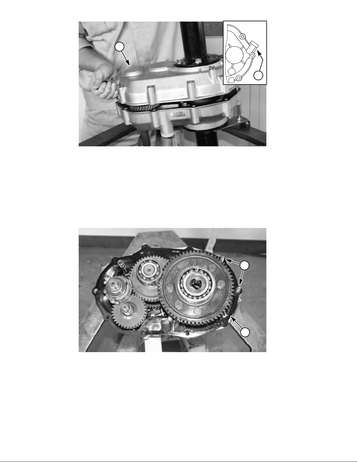
1
Figure 24
1. Case (RH) 2. Governor boss
2
IMPORTANT: Make sure to not hit the governor
boss too hard when separating the cases, the boss
may get damaged. Do not pry open the two cases
with a screw driver, damage may result to the sealing surfaces.
2. Remove input shaft, center shaft and differential a ssemblies.
G. Hold the case (RH) and lift up while lightly tapping
the governor boss with a plastic hammer.
2
1
1. Gasket 2. Pipe knock
A. Remove gasket and pipe knocks.
Figure 25
Workman MDX--DPage 4 -- 24Drive Train
Page 59

4
1
Figure 26
1. Counter shaft
2. Spacer (2 used)
B. Pull out counter shaft. Remove spacer, needle
bearing, gear 34 and spacer.
3
2
3. Needle bearing
4. Gear 34
Drive Train
2
1
Figure 27
1. Counter shaft
2. Spacer (2 used)
C. Replace counter shaft if it has abnormal wear,
cracks or damage.
D. Replace spacer if either one is cracked or bent.
3
2
4
3. Needle bearing
4. Gear 34
E. Replace needle bearing if needles are bent, do
not rotate freely or do not remain in the bearing cage.
F. Replace gear 34 if worn or damaged. Cracked,
broken, missing or chipped gear teeth are not acceptable.
Workman MDX--D Drive TrainPage 4 -- 25
Page 60

4
2
1. Differential assembly
2. Input shaft assembly
3
1
Figure 28
3. Center shaft assembly
4. Shift shaft
IMPORTANT: Make sure to not damage the oil seal
when removing the input shaft.
NOTE: If any of the assemblies can not be pulled out by
hand, hold the assembly while gently tapping the case
with a plastic hammer. Make sure to tap equally around
the case.
3. Remove axle case from case (RH and LH).
1
G. Lift up differential assembly, center shaft assembly and input shaft assembly at the same time. First,
remove input shaft assembly. Then, remove center
shaft assembly with the shift shaft and differential assembly.
2
3
Figure 29
1. Flange bolt
2. Axle case
A. Remove remaining two (2) flange bolts securing
each axle case to the case. Remove axle case from
the transaxle case.
3. Transaxle case
Workman MDX--DPage 4 -- 26Drive Train
Page 61

2
4
Figure 30
1. Snap ring
2. Axle case
IMPORTANT: Do not reuse snap ring. Discard and
replace ring with new one.
B. Remove snap ring from the axle case. Remove
axle shaft from case.
IMPORTANT: When replacing ball bearings, both
ball bearings must be replaced as a set.
4. Disassemble input shaft assembly.
1
3. Axle shaft
4. Ball bearing
3
C. Ball bearing r oller balls must be free of deformation and scoring. Ball bearing must spin freely and
have minimum axial play. Replace ball bearing as
necessary.
1
Drive Train
Figure 31
1. Ball bearing 2. Input shaft
IMPORTANT: Do not reuse ball bearings that have
been removed.
Workman MDX--D Drive TrainPage 4 -- 27
2
A. Remove ball bearing from the input shaft with a
bearing puller.
Page 62

1
2
Figure 32
1. Input shaft 2. Ball bearing
B. Replace input shaft if worn or damaged. Gear
teeth that are cracked, broken, chipped or missing
are not acceptable.
5. Disassemble center shaft assembly .
2
C. Ball bearing roller balls must be free of deformation and scoring. Ball bearing must spin freely and
have minimum axial play. Replace ball bearing as
necessary.
1
Figure 33
1. Ball bearing 2. Ball bearing
IMPORTANT: Do not reuse ball bearings that have
been removed.
A. Remove ball bearings from the center shaft assembly. Discard removed bearings.
Workman MDX--DPage 4 -- 28Drive Train
Page 63

5
8
83
2
7
4
6
1
Figure 34
1. Gear 55
2. Gear 47
3. Gear (small)
4. Ball bearing
5. Ball bearing
B. Remove gears, pin clutch, collars and spacer
from the input shaft.
C. Replace gears if worn or damaged. Cracked, broken, missing or chipped gear teeth are not acceptable.
9
6. Pin clutch
7. Center shaft
8. Collar (2 used)
9. Spacer
D. Replace center shaft if worn or damaged. Splines
that are cracked, broken, chipped or missing are not
acceptable.
E. Replace pin clutch if cracked or bent.
F. Replace collars or spacer if excessively worn or
damaged. Replace both collars as a set.
Drive Train
Workman MDX--D Drive TrainPage 4 -- 29
Page 64

6. Disassemble differential case assembly.
1
1. Bolt (6 used)
2. Gear 62
A. Remove six (6) bolts securing gear 62 to the differential c ase.
2
3
Figure 35
3. Differential case
4
3
2
Figure 36
1. Spring pin
2. Differential case
NOTE: The spring pin can be punched out from the hole
on the opposite side of gear 62.
B. Remove spring pin from the differential case. Discard pin and replace it with new spring pin.
4
1
3. Pinion shaft
4. Pinion gear
C. Remove pinion shaft and gears from the case.
Separate gears from shaft.
Workman MDX--DPage 4 -- 30Drive Train
Page 65

5
4
3
6
2
8
1
Figure 37
1. Side gear (2 used)
2. Pinion gear (2 used)
3. Gear 34
4. Ball bearing
D. Replace gears if worn or damaged. Cracked, broken, missing or chipped gear teeth are not acceptable.
E. Ball bearing roller balls must be free of deformation and scoring. Ball bearing must spin freely and
have minimum axial play. Replace ball bearing as
necessary.
7
5. Differential case
6. Pinion shaft
7. Spring pin
8. Bolt (6 used)
F. Replace case if machined areas where the side
and pinion gears mesh are scored or if the pinion
shaft fits loosely in its bore.
G. Replacepinionshaftifcrackedorbent.
H. Replace oil seal if cracked, nicked or distorted
such that it would not hold a proper seal.
Drive Train
Workman MDX--D Drive TrainPage 4 -- 31
Page 66

Transaxle Assembly
1. Assemble input shaft assembly.
1
2
Figure 38
1. Ball bearing 2. Input shaft
IMPORTANT: Make sure to press ball bearing at the
inner race to prevent damaging the ball bearing.
A. Press ball bearing onto the input shaft.
Workman MDX--DPage 4 -- 32Drive Train
Page 67

2. Assemble the center shaft assembly.
4
7
9
3
1
6
5
8
5
2
5.386” to 5.398”
(136.8 to 137.1 mm)
Figure 39
1. Pin clutch
2. Center shaft
3. Gear 47
4. Gear 55
5. Collar
NOTE: Before assembling, apply molybdenum disul-
fide grease to the inside of gears 47 and 55.
6. Gear (small)
7. Bearing
8. Bearing
9. Spacer
A. Slide pin clutch onto the centershaft. Install gears
47 and 55 onto shaft noting correct orientation of
gears. Slide collars, small gear and spacer onto the
center shaft.
1
Drive Train
2
Figure 40
1. Ball bearing 2. Ball bearing
B. Press ball bearings onto the center shaft using a
bearing press.
Workman MDX--D Drive TrainPage 4 -- 33
C. Make sure distance from one ball bearing outer
edge to the other ball bearing outer edge is 5.386” to
5.398” (136.8 to 137.1 mm) (Fig. 39).
Page 68
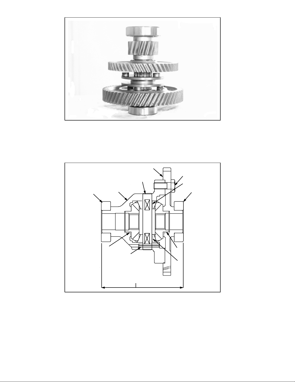
D. The center shaft should appear as above when
assembled.
3. Assemble differential assembly.
8
4
Figure 41
2
5
6
1
9
3
7
4.854” to 4.882”
(123.3 to 124.0 mm)
Figure 42
1. Pinion gear (greased surface)
2. Pinion shaft
3. Side gear (greased surface)
4. Differential case
5. Gear 62
A. Apply molybdenum disulfide grease to the inside
of both pinion gears where they contact the pinion
shaft. Apply molybdenum disulfide grease to the outside of both side gears where they contact the differential case and gear 62.
3
1
6. Bolt
7. Spring pin
8. Ball bearing
9. Ball bearing
Workman MDX--DPage 4 -- 34Drive Train
Page 69

1
Figure 43
1. Side gear
2. Pinion gear
B. Install side gear, both pinion gears and pinion
shaft into the differential case.
4
3
2
3. Pinion shaft
4. Differential case
2
Figure 44
1. Spring pin
2. Differential case
C. Align pinion shaft hole and install new spring pin
through the differential case and pinion shaft.
1
3
3. Pinion shaft
Drive Train
Workman MDX--D Drive TrainPage 4 -- 35
Page 70

3
1
2
4
Figure 45
1. Side gear
2. Pinion gear
3. Gear 62
4. Differential case
D. Install remaining side gear to the pinion gears. E. Secure gear 62 to the differential case with six (6)
bolts. Torque bolts in a crossing pattern from 40 to 45
ft--lb (54 to 61 N--m).
40 to 45 ft--lb
(54to61N--m)
Figure 46
IMPORTANT: The length from the outer most side of
each ball bearing must be from 4.854” to 4.882”
(123.3 to 124.0 mm) (Fig. 42).
F. If ball bearings were removed, press new ball
bearings onto differential case and gear 62.
G. The differential assembly should appear as
above when assembled.
Workman MDX--DPage 4 -- 36Drive Train
Page 71
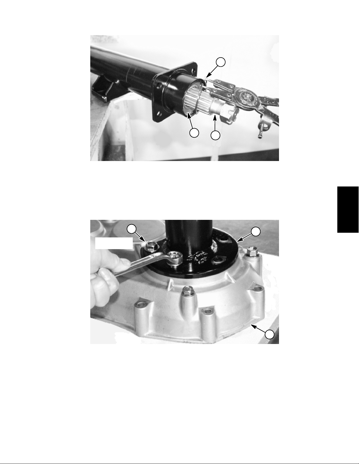
4. Installaxlecasetocase(RHandLH).
2
Figure 47
1. Axle shaft
2. Snap ring
IMPORTANT: Do not reuse snap ring. Replace snap
ring with new one.
3
25 to 31 ft --lb
(34to42N--m)
3
3. Ball bearing
1
A. Insert axle shaft with snap rings, collar and ball
bearings into the axle case. Install snap ring to the
axle case.
1
Drive Train
Figure 48
1. Axle case
2. Case
3. Flange bolt
IMPORTANT: Make sure to install the axle case to
the proper side of the case. The right side of the
case takes the short axle case, and the left side
takes the long axle case.
IMPORTANT: Make sure to not damage the oil seal
when installing the axle case to the case.
Workman MDX--D Drive TrainPage 4 -- 37
2
B. Install axle case to the case. Secure each axle
case to the case with flange bolts. Torque bolts from
25 to 31 ft--lb (34 to 42 N--m).
Page 72

5. Install input shaft, center shaft and differential assemblies to the case.
2
Figure 49
1. Shift shaft 2. Clutch groove
A. Insert fork of the shift shaft to the clutch groove of
the center shaft assembly.
3
2
1
1
4
Figure 50
1. Center shaft assembly
2. Shift shaft
B. Replace oil seals for the input and selector shafts
on the case (LH) if cracked, nicked or distorted such
that they would not hold a proper seal.
IMPORTANT: Make sure to not damage the oil seal
when installing the input shaft.
3. Input shaft
4. Differential assembly
C. Install center shaft assembly with shift shaft and
differential assembly. Then, install input shaft assembly. Lower differential assembly, center shaft assembly and input shaft assembly into the case at the
same time.
Workman MDX--DPage 4 -- 38Drive Train
Page 73

Figure 51
1. Fork (selector shaft) 2. Pin (shift shaft)
D. Make sure the selector shaft fork is contacting the
pinontheshiftshaft.
1
2
Drive Train
1
2
Figure 52
1. Spacer 2. Boss (counter shaft)
E. Place spacer on the counter shaft boss of the
case (LH) so the oil groove faces up.
Workman MDX--D Drive TrainPage 4 -- 39
Page 74

1. Gear 34
2. Counter shaft
2
3
1
Figure 53
3. Spacer
F. Apply molybdenum disulfide grease to the inside
of gear 34 and the contact surface between the case
and the counter shaft.
6. Assemble case (LH and RH).
1
G. Place gear 34 onto the spacer. Make sure not to
drop the spacer. Insert needle bearing into gear. Insert counter shaft with remaining spacer through the
needle bearing, gear 34 and into the spacer and
case.
2
Figure 54
1. Case (sealing surface) 2. Pipe knock
A. Make sure gasket sealing surfaces of both cases
are clean. Install gasket to case.
B. Install both pipe knocks to the c ase (LH).
Workman MDX--DPage 4 -- 40Drive Train
Page 75

1
Figure 55
1. Cable bracket 2. Flange bolt
15 to 18 ft--lb
2
(21 to 25 N--m)
NOTE: Keep the gasket sealing surfaces of the cases
as horizontal to each other as possible. If the sealing
surfaces do not join to each other, tap the case lightly
with a plastic hammer.
C. Install case (RH) so each shaft fits properly into
the case.
D. Position cable bracket to transaxle cases.
E. Secure case (RH) to case (LH) with flange bolts
and nuts. Torque bolts from 15 to 18 ft--lb (21 to 25
N--m).
25 to 31 ft--lb
(34to42N--m)
Drive Train
2
1
Figure 56
1. Axle bracket 2. Flange bolt
F. Position axle bracket to each axle case. Secure
axle bracket to each axle case with flange bolts.
Torque bolts from 25 to 31 ft--lb (34 to 42 N--m).
Workman MDX--D Drive TrainPage 4 -- 41
Page 76

12 to 15 ft--lb
(16 to 20 N--m)
2
1
Figure 57
1. Cable bracket 2. Bolt (steel ball, spring & gasket)
G. Install steel ball, spring, gasket and bolt. Torque
bolt from 12 to 15 ft--lb (16 to 20 N--m).
H. Fill transaxle with 1.5 quarts (1.4 liters) of new
SAE 10W--30 motor oil.
Workman MDX--DPage 4 -- 42Drive Train
Page 77

Table of Contents
Chapter 5
Electrical System
GENERAL INFORMATION 2.....................
Operator’s Manual 2..........................
Electrical Drawings 2..........................
SPECIAL TOOLS 3.............................
TROUBLESHOOTING 5.........................
Starting Problems 5...........................
General Run Problems 6......................
ELECTRICAL SYSTEM QUICK CHECKS 7........
Battery Test 7................................
Charging System Test 7.......................
Glow Plug Test 7.............................
COMPONENT TESTING 8.......................
Ignition Switch 8..............................
Indicator Lights 9.............................
Fuse Blocks 10...............................
Fusible Links 11...............................
Hour Meter 12................................
Headlight Switch 12...........................
Brake Switch 13..............................
Main Power and Glow Relays 14................
Start Relay 15................................
Glow Plug Controller 16.......................
Engine Run Solenoid 17.......................
Over Temperature Switch 18...................
Fuel Pump 19................................
Oil Pressure Switch 20........................
Backup Alarm (Optional Kit) 21.................
BackupSwitch(OptionalKit) 22................
SERVICE AND REPAIRS 23.....................
Battery Service 23............................
Battery Removal 23..........................
Battery Inspection and Maintenance 24........
Battery Installation 24........................
Battery Testing 25...........................
Battery Charging 26.........................
Battery Storage 26..........................
Electrical
System
Workman MDX--D Electrical SystemPage 5 -- 1
Page 78

General Information
Operator’s Manual
The Operator’s Manual provides information regarding
the operation, general maintenance and maintenance
intervals for your Workman vehicle. Refer to the Operator’s Manual for additional information when servicing
the machine.
Electrical Drawings
The electrical schematic and other electrical drawings
for the Workman MDX--D are located in Chapter 7 -Electrical Drawings.
Electrical System
Page 5 -- 2
Workman MDX--D
Page 79

Special Tools
Order special tools from your Toro Distributor. Some
tools may also be available from a local supplier.
Multimeter
The meter can test electrical components and circuits
for current, resistance or voltage.
NOTE: Toro recommends the use of a DIGITAL Volt-Ohm--Amp multimeter when testing electrical circuits.
The high impedance (internal resistance) of a digital meter in the voltage mode will make sure that excess current is not allowed through the meter. This excess
current can cause damage to circuits not designed to
carry it.
Figure 1
Skin--Over Grease
Special non--conductive grease which forms a light protective skin which helps waterproof electrical switches
and contacts.
Toro Part Number: TOR50547
Battery Terminal Protector
Aerosol spray that should be used on battery terminals
to reduce corrosion problems. Apply terminal protector
after the battery cable has been secured to the battery
terminal.
Toro Part Number: 107--0392
Figure 2
Electrical
System
Workman MDX--D Electrical SystemPage 5 -- 3
Figure 3
Page 80

Dielectric Lubricant/Sealant
Dielectric lubricant should be used to prevent corrosion
of non--sealed connection terminals. To ensure complete coating of terminals, liberally apply lubricant to
both component and wire harness connector, plug connector to component, unplug connector, reapply lubricant to both surfaces and reconnect harness connector
to component. Connectors should be thoroughly
packed with lubricant for effective results.
Toro Part Number: 107--0342
Battery Hydrometer
Use the Battery Hydrometer when measuring specific
gravity of battery electrolyte. Obtain this tool locally.
Figure 4
Figure 5
Electrical System
Page 5 -- 4
Workman MDX--D
Page 81

Troubleshooting
For effective troubleshooting and repairs, you must
CAUTION
Remove all jewelry, especially rings and
watches, before doing any electrical troubleshooting or testing. Disconnect the battery
cables unless the test requires battery voltage.
Starting Problems
Problem Possible Causes
Starter solenoid clicks, but starter will not crank. Battery is discharged.
have a good understanding of the electrical circuits and
components used on this vehicle (see electrical drawings in Chapter 7 -- Electrical Drawings).
If the vehicle has any interlock switches by--passed,
they must be reconnected for proper troubleshooting
and safety.
Battery cables are loose or corroded.
Battery ground to frame is loose or corroded.
Wiring at starter is faulty.
Starter solenoid is faulty.
Starter is faulty and causing an incomplete circuit for
the starter solenoid.
Nothing happens when start attempt is made. Brake pedal is not depressed.
Battery is discharged.
In--line primary fuse (10 ampere) is loose or faulty.
Battery cables are loose or corroded.
Battery ground to frame is loose or corroded.
Wiring to the start circuit components is loose,
corroded or damaged (see electrical drawings in
Chapter 7 -- Electrical Drawings).
Brake pedal switch is out of adjustment or faulty.
Start relay or circuit wiring is faulty.
The ignition switch or circuit wiring is faulty.
Fuseblockisfaulty.
Fusible link harness at the engine starter motor has
faulty link(s) so battery power is not available to vehicle
electrical system.
Electrical
System
Starter solenoid or circuit wiring is faulty.
Workman MDX--D Electrical SystemPage 5 -- 5
Page 82

Starting Problems (Continued)
Problem Possible Causes
Engine cranks, but does not start. Fuel tank is empty.
Wiring to start circuits is loose, corroded or damaged
(see electrical drawings in Chapter 7 -- Electrical
Drawings).
Engine or fuel system is malfunctioning (see Chapter 3
-- Diesel Engine).
15 ampere fuse in fuse block is faulty.
Fuel pump or circuit wiring is faulty.
Glow plugs, glow relay or glow plug controller are
faulty.
Wire harness fusible link to run solenoid pull coil is
faulty.
Engine and fuel may be too cold.
Run solenoid is faulty.
General Run Problems
Problem Possible Causes
Battery does not charge. Wiring to the charging circuit components is loose,
corroded or damaged (see electrical drawings in
Chapter 7 -- Electrical Drawings).
Alternator or circuit wiring is faulty.
Battery is faulty.
Engine stops during operation. Wiring to the run circuit components became broken or
disconnected (see electrical drawings in Chapter 7 -Electrical Drawings).
Engine or fuel system is malfunctioning (see Chapter 3
-- Diesel Engine).
Electrical System
Page 5 -- 6
Workman MDX--D
Page 83

Electrical System Quick Checks
Battery Test
Use a multimeter to measure the voltage between the
battery terminals.
Set the multimeter to the DC volts setting. The battery
should be at a temperature of 60
C). The ignition key should be off and all accessories
turned off. Connect the positive (+) meter lead to the
positive battery post and the negative (--) meter lead to
the negative battery post.
NOTE: This test provides a relative condition of the battery. Load testing of the battery will provide additional
and more accurate information.
o
to 100oF(16oto 38
Charging System Test
This is a simple test used to determine if a charging system is functioning. It will tell you if the charging system
has an output, but not its capacity.
Remove battery cover to gain access to battery. Use a
digital multimeter set to DC volts. Connect the positive
(+) multimeter lead to the positive battery post and the
negative (--) multimeter lead to the negative battery
post. Keep the test leads connected to t he battery posts
and record the battery voltage.
NOTE: When starting the engine, the battery voltage
will drop and then should increase once the engine is
running.
NOTE: Depending upon the condition of the battery
charge and battery temperature, the battery voltage will
increase at different rates as the battery charges.
Voltage Measured
12.68 V (or higher) Fully charged (100%)
o
Make sure the shift lever is in the neutral position and the
parking brake is applied. Start the engine and run engine at high idle (above 3000 RPM). Maintain engine
speed to allow the battery to charge for at least three (3)
minutes. Record the battery voltage.
After running the engine for at least three (3) minutes,
battery voltage should be at least 0.50 volt higher than
initial battery voltage.
An example of a charging system that is functioning:
At least 0.50 volt over initial battery voltage.
Initial Battery Voltage = 12.30 v
Battery Voltage after 3 Minute Charge = 12.95 v
Difference =+0.65v
12.45 V 75% charged
12.24 V 50% charged
12.06 V 25% charged
11.89 V 0% charged
Battery Charge Level
Electrical
System
Glow Plug Test
This is a fast, simple test that can help to determine the
integrity and operation of your Workman MDX--D glow
plug system. The test should be run anytime hard starting (cold engine) is encountered on a diesel engine
equipped with a glow plug system.
Use a digital multimeter and/or inductive Ammeter (AC/
DC Current Transducer). Properly connect the ammeter
to the digital multimeter (refer to manufacturers’ instructions) and set the multimeter to the correct scale. With
the ignition switch in the OFF position, place the
Workman MDX--D Electrical SystemPage 5 -- 7
ammeter pickup around the main glow plug power supply wire and read the meter prior to activating the glow
plug system. Adjust the meter t o read zero (if applicable). Activate the glow plug system by turning the ignition switch to ON and record the multimeter results.
The Workman MDX--D glow plug system should have a
reading of approximately nine (9) amps per glow plug
(18 amps total). If low current reading is observed, one
(or more) of the glow plugs is faulty.
Page 84

Component Testing
For accurate resistance and/or continuity checks, electrically disconnect the component being tested from the
circuit (e.g. unplug the ignition switch connector before
doing a continuity check on the switch).
NOTE: See the Kubota Workshop Manual, Diesel Engine, SM--E3B Series for engine component testing information.
Ignition Switch
The ignition (key) switch has three positions (OFF, ON
andSTART).Theignitionswitchislocatedonthedash
panel (Fig. 6).
Testing
The switch terminals are identified as shown in Figure
7. The circuit wiring of the ignition switch is shown in the
chart below. With the use of a multimeter (ohms setting),
the switch functions may be t ested to determine whether
continuity exists between the various switch terminals
for each switch position. Disconnect wire harness connector from key switch and verify continuity between
switch terminals in the different switch positions.
POSITION
OFF NONE
ON B+C+F, D+E
STAR T A+B+C
CIRCUITS
CAUTION
When testing electrical components for continuity with a multimeter (ohms setting), make sure
that power to the circuit has been disconnected.
1
2
Figure 6
1. Dash panel 2. Ignition switch
RUN
OFF
45
o
45
o
START
After testing is completed, connect wire harness connector to ignition switch.
Electrical System
Page 5 -- 8
FRONT VIEW
Figure 7
A
B
C
REAR VIEW
Workman MDX--D
F
E
D
Page 85

Indicator Lights
Charge Indicator Light
The charge indicator light should come on when the ignition switch is in the ON position with the engine not running. Also, it should illuminate with an improperly
operating charging circuit while the engine is running.
Engine Oil Pressure Light
The engine oil pressure light should come on when the
ignition switch is in the ON position with the engine not
running. Also, it should illuminate with the engine running if the engine oil pressure drops to an unsafe level.
2
1
3
4
IMPORTANT: If the oil pressure indicator light is illuminated with the engine running, shut off the engine immediately.
To test the oil pressure light and circuit wiring, ground the
wire attached to oil pressure switch located on the engine near the oil filter. Turn ignition switch to the ON position; the engine oil pressure light should come on
indicating correct operation of the indicator light and circuit wiring.
Engine Temperature Light
If the engine coolant temperature reaches 230
o
C) (approximate), the engine temperature light will
(110
o
come on.
To test the engine t emperature light and circuit wiring,
turn ignition switch to the ON position and ground the
wire attached to over temperature switch located on the
engine water pump housing (see Over Temperature
Switch in this section). The engine temperature light
should illuminate while the wire is grounded.
Glow Plug Indicator Light
Figure 8
1. Charge Indicator
2. Engine oil pressure
3. Engine temperature
4. Glow plug indicator
5
2
F
1
1B (--)
6
1A (+)
3
4
System
Electrical
2A (+)2B (--)
The glow plug light should come on when the ignition
switch is placed in the ON position prior to placing the
ignition switch in START. The light should stay lit for
approximately six (6) seconds while the ignition switch
is left in the ON position.
Testing Indicator Lights
1. Apply 12 VDC to indicator light terminals 1A and 2A
(Fig. 9).
2. Ground indicator light terminals 1B and 2B (Fig. 9).
3. Both indicator lights should illuminate.
Workman MDX--D Electrical SystemPage 5 -- 9
1. Charge indicator
2. Engine oil pressure
3. Engine temperature
Figure 9
4. Glow plug indicator
5. Indicator light front
6. Indicator light back
Page 86

Fuse Blocks
The fuse block on Workman MDX--D vehicles is located
beneath the dash panel.
In addition to the fuses in the fuse block, an in--line 10
amp fuse is included in the wire harness. This fuse protects the ignition switch circuits and also provides protection for the optional brake and signal light kit. The
in-- line fuse resides in a fuse holder under the dash panel near the fuse blocks (Fig. 11).
Fuse Identification and Function
Use F igure 10 to identify each individual fuse in the fuse
block.
The upper row of fuses protect circuits as follows:
1. The extreme left 10 ampere fuse protects the power
point circuit. This fuse also protects the circuit for the optional backup alarm (if equipped).
2. The middle left 10 ampere fuse protects the engine
start circuit.
3. The middle right 10 ampere fuse protects the light
circuit.
2
1. Fuse blocks
2. Fuse decal
3
4
1
Figure 10
3. Upper fuses
4. Lower fuses
4. The extreme right 15 ampere fuse protects the circuits for engine electrical components and also dash indicators (hour meter and indicator lights).
The lower row of fuses protect circuits as follows:
1. The extreme left fuse position is not used.
2. Themiddleleft15amperefuseprotectsthecircuitfor
the optional cargo box lift.
3. The middle right 15 ampere fuse protects the circuit
for the optional rear lift kit.
4. The extreme right 30 ampere fuse protects the circuit
for the horn (if equipped).
Fuse Testing
Make sure that ignition switch is OFF and key is removed from switch. Remove fuses from the fuse block
for testing. A fuse in usable condition should have continuity between the fuse terminals. A faulty fuse will not
have continuity between the fuse terminals.
1
2
Figure 11
1. In--line fuse 2. Fuse block
Electrical System
Page 5 -- 10
Workman MDX--D
Page 87

Fusible Links
The Workman MDX--D uses four (4) fusible links for circuit protection. Three (3) of these fusible links are included in a wire harness that connects the starter B+
terminal to the vehicle wire harness (Fig. 12). The remaining fusible link is included in the engine wire harness and connects the starter G terminal to the engine
run solenoid pull coil. If any of these links should fail, current to the protected circuit will cease. Refer to the electrical schematic and wire harness drawings in Chapter
7 -- Electrical Drawings for additional circuit information.
Testing
Make sure that ignition switch is OFF. Disconnect negative battery cable from battery terminal and then disconnect positive cable from battery (see Battery Service in
the Service and Repairs section of this chapter). Locate
and unplug fusible link connector. Use a multimeter to
make sure that continuity exists between the fusible link
terminals. If a fusible link is open, replace the link.
After testing is complete, make sure that fusible link is
securely attached to engine component and wire harness. Connect positive battery cable to battery terminal
first and then connect negative cable to battery.
FUSIBLE LINK
FUSIBLE LINK
FUSIBLE LINK
Figure 12
Electrical
System
Workman MDX--D Electrical SystemPage 5 -- 11
Page 88

Hour Meter
Testing
IMPORTANT: Make sure to observe polarity on the
hour meter terminals when testing. Damage to the
meter may result from an improper connection.
1. Unplug wire harness connector from hour meter.
2. Connect positive (+) terminal of a 12 VDC source to
the positive terminal of the hour meter.
3. Connect negative (--) terminal of the voltage source
to the other terminal of the hour meter.
4. The hour meter should move 1/10 of an hour in six
(6) minutes.
5. Disconnect voltage source from the hour meter. Reconnect wire harness connector to hour meter.
Headlight Switch
The headlight switch is located on the dash panel (Fig.
14). This rocker switch allows the headlights to b e
turned on and off.
QUARTZ
1
00000
HOURS
1/10 WHEEL: WHITE W/BLACK NUMBERS
HOUR WHEELS: BLACK W/WHITE NUMBERS
--
10
RUNNING: INDICATOR
WINDOW
Figure 13
2
1
Testing
The switch terminals are marked as shown in Figure 15.
The circuitry of the headlight switch is shown in the chart
below. With the use of a multimeter (ohms setting), the
switch functions may be tested to determine whether
continuity exists between the various terminals for each
position. Verify continuity between switch terminals.
SWITCH
POSITION
NORMAL
CIRCUITS
OTHER
CIRCUITS
ON 2+3 5+6
OFF 1+2 4+5
Figure 14
1. Dash panel 2. Headlight switch
BACK OF SWITCH
Figure 15
Electrical System
Page 5 -- 12
Workman MDX--D
Page 89

Brake Switch
The brake switch is a normally closed switch that opens
when the brake pedal is not applied. When the brake
pedal is applied, the brake pedal moves away from the
switch plunger to allow the switch to be in its normally
closed state. The brake switch is attached to the pedal
support frame under the dash panel (Fig. 16).
Testing
1
1. Park vehicle on a level surface, stop engine, apply
parking brake and remove key from ignition switch.
2. Locate brake switch for testing. Disconnect vehicle
wire harness electrical connector from the brake switch.
3. Check the continuity of the switch by connecting a
multimeter (ohms setting) across the connector terminals.
4. When the switch plunger is extended (brake pedal is
applied), there should be continuity (closed) between
the switch terminals.
5. When the switch p lunger is depressed (brake pedal
is not applied), there should not be continuity (open) between the switch terminals.
6. Replace brake switch if testing determines that it is
faulty. When installing switch, make sure that the brake
pedal does not bottom switch when the pedal is released.
7. If the brake switch tests correctly and a circuit problem still exists, check wire harness (see Electrical
Schematic and Circuit Drawings in Chapter 7 -- Electrical Drawings).
Figure 16
1. Brake pedal assembly 2. Brake switch
2
System
Electrical
8. When switch testing is completed, connect switch
connector to vehicle wire harness.
Workman MDX--D Electrical SystemPage 5 -- 13
Page 90

Main Power and Glow Relays
The Workman MDX--D main and glow relays are attached to the front of the dash bracket and can be accessed by raising the hood (Fig. 17). The vehicle wire
harness is attached to the main and glow relays with four
(4) wire connectors. Relays can be identified by a tag on
thewireharness.
The main power relay is used to provide current to the
fuse blocks. When the ignition switch is in the ON or
START position, the main power relay is energized.
The glow relay is used to provide current to the engine
glow plugs when the relay is energized by the glow plug
controller.
2
1
Testing
1. Park vehicle on a level surface, stop engine, apply
parking brake and remove key from ignition switch.
Open and support hood to access relays.
2. Make sure ignition switch is in the OFF position. Disconnect wire harness electrical connector from relay
that is to be tested. Remove relay from dash bracket for
easier testing.
NOTE: Prior to taking small resistance readings with a
digital multimeter, short the meter test leads together.
The meter will display a small resistance value (usually
0.5 ohms or less). This resistance is due to the internal
resistance of the meter and test leads. Subtract this value from the measured value of the relay being testing.
3. Verify coil resistance between terminals 85 and 86
with a multimeter (ohms setting). Resistance should be
approximately 72 ohms.
4. Connect multimeter (ohms setting) leads to relay terminals 30 and 87. Ground terminal 86 and apply +12
VDC to terminal 85. The relay should make and break
continuity between terminals 30 and 87 as +12 VDC is
applied and removed from terminal 85.
Figure 17
1. Main power relay 2. Glow relay
30
85 86
87
86 87
85 30
Figure 18
5. Disconnect voltage and leads from the relay terminals. Replace relay if testing determines that it is faulty.
6. Secure relay to dash bracket and connect wire harness electrical connector to relay after testing is completed.
7. Close and secure hood.
Electrical System
Page 5 -- 14
Workman MDX--D
Page 91

Start Relay
The Workman MDX--D start relay provides electrical
current to the engine starter solenoid when energized.
The relay is energized when the ignition switch is in the
START position and the brake pedal is depressed
(brake switch closed). The start relay is attached to the
front of the dash bracket and can be accessed by raising
the hood (Fig. 19). The vehicle wire harness is attached
to the start relay with a five (5) wire connector. The relay
canbeidentifiedbyatagonthewireharness.
Testing
1. Park vehicle on a level surface, stop engine, apply
parking brake and remove key from ignition switch.
Open and support hood to access start relay.
2. Locate start relay and disconnect the machine wire
harness connector from the relay. Remove relay from
from dash bracket for easier testing.
NOTE: Prior to taking small resistance readings with a
digital multimeter, short the meter test leads together.
The meter will display a small resistance value (usually
0.5 ohms or less). This resistance is due to the internal
resistance of the meter and test leads. Subtract this value from the measured value of the relay being testing.
3. Using a multimeter (ohms setting), measure coil resistance between terminals 85 and 86 (Fig. 20). Resistance should be between 70 and 90 ohms.
4. Connect multimeter (ohms setting) leads to relay terminals 30 and 87. Ground terminal 86 and apply +12
VDC t o terminal 85. The relay terminals 30 and 87
should have continuity as +12 VDC is applied to terminal
85. The relay terminals 30 and 87 should not have continuity as +12 VDC is removed from terminal 85.
1
Figure 19
1. Start relay 2. Wire harness
1
868587A 87
3
30
1
Figure 20
1. Coil terminal
2. Common terminal
3. Normally closed term.
4. Normally open term.
2
4
2
System
Electrical
5. Disconnect voltage from terminal 85 and multimeter
lead from terminal 87.
6. Connect multimeter (ohms setting) leads to relay terminals 30 and 87A. With terminal 86 grounded, apply
+12 VDC to terminal 85. The relay terminals 30 and 87A
should not have continuity as +12 VDC is applied to terminal 85. The relay terminals 30 and 87A should have
continuity as +12 VDC is removed from terminal 85.
7. When relay testing is completed, disconnect voltage
and multimeter leads from the relay terminals. Replace
relay if testing determines that it is faulty.
8. Secure relay to machine and connect machine wire
harness connector to relay.
9. Lower and secure hood.
Workman MDX--D Electrical SystemPage 5 -- 15
Page 92

Glow Plug Controller
The glow plug controller is attached to the front of the
dash bracket and can be accessed by raising the hood
(Fig. 21).
NOTE: When troubleshooting the glow controller, refer
to electrical drawings in Chapter 7 -- Electrical Drawings.
Glow Plug Controller Operation
1. When the ignition switch is initially placed in the ON
position, the glow plug controller energizes the glow
plugs for six (6) seconds. The console glow plug indicator light will also be illuminated for six (6) seconds.
2. When the ignition switch is turned to the START position, the glow plugs will energize as long as the switch
is held in START. The console glow plug indicator light
will not be illuminated.
3. When the ignition switch is released from the START
to the ON position, the glow plugs will de--energize and
the console glow plug indicator light will remain off.
Glow Plug Controller Checks
1. Make sure there is electrical power from the battery.
5. If any of the conditions in Step 3 are not met or electrical power to controller terminal 1 exists and any of the
other conditions in Step 4 are not met:
A. Verify continuity of the circuitry from the battery to
the glow relay and glow plugs (see Chapter 7 -- Electrical Drawings).
B. Verify continuity of the circuitry from the battery to
ignition switch, glow plug controller, glow plug indicator light, glow relay and ground (see Chapter 7 -Electrical Drawings).
C. Repair or replace components as necessary.
6. After testing is completed, connect wire harness
electrical connector to the engine run solenoid.
1
2. Disconnect the wire harness electrical connector
from the engine run solenoid to prevent the engine from
starting (see Engine Run Solenoid in this section).
3. Place ignition s witch in the ON position. Verifythe following while in the ON position:
A. Glow plug indicator light is illuminated.
B. Glow relay is energized.
C. Glow plugs are energized.
D. Glow plug indicator light goes out and glow plugs
de--energize after approximately six (6) seconds.
4. PlaceignitionswitchintheSTARTposition.Verify
thefollowingwhileintheSTARTposition:
A. Glow plug indicator light is not illuminated.
B. Glow relay is energized.
C. Glow plugs are energized.
D. Electrical power exists at terminal 1 of the glow
plug controller.
NOTE: If there is no electrical power at terminal 1 of the
glow plug controller, verify continuity of the circuitry from
the ignition switch to the controller and perform Step 4
again (see Chapter 7 -- Electrical Drawings).
Electrical System
Page 5 -- 16
Figure 21
1. Glow plug controller 2. Wire harness
3
2
1
1
VIOLET
ORANGE
PINK
CONTROLLER
CONNECTIONS
1
START
LAMP
2
+12V
3
TEMP (not used)
4
GLOW
5
GROUND
6
GRAY
BLACK
Figure 22
1. Controller top view 2. Controller end view
Workman MDX--D
2
6
5
4
2
Page 93

Engine Run Solenoid
The engine run solenoid used on Workman MDX--D
vehicles must be energized for the diesel engine to run.
The run solenoid is mounted totheinjectionpumponthe
engine (Fig. 23). The run solenoid is energized when the
ignition switch is in either the ON or START position.
The engine run solenoid includes two (2) coils for operation: the pull coil and the hold coil. When the ignition
switch is turned to START, the fuel solenoid pull coil is
energized and the solenoid plunger retracts. Once the
plunger is retracted, the hold coil will keep it retracted for
continued engine operation. When the solenoid is de-energized, the plunger extends to shut off fuel supply to
theenginecausingtheenginetostoprunning.
NOTE: A fusible link in the engine wire harness protects
the engine run solenoid pull coil circuit. If this link should
fail, the run solenoid will not function and the engine will
not run. Refer to electrical drawings in Chapter 7 -- Electrical Drawings when troubleshooting the run solenoid.
NOTE: See Kubota Workshop Manual, Diesel Engine,
SM--E3B Series for information regarding engine run
solenoid testing procedure.
1
2
Figure 23
1. Engine assembly 2. Engine run solenoid
Electrical
System
Workman MDX--D Electrical SystemPage 5 -- 17
Page 94

Over Temperature Switch
The over temperature switch is located on the engine
thermostat housing near the alternator (Fig. 24). If the
engine coolant temperature reaches 230
(approximate), the over temperature switch closes
which causes the dash panel engine temperature light
to come on. The over temperature switch has a gray wire
connected to it.
Switch Testing
o
F(110oC)
CAUTION
Make sure engine is cool before removing the
temperature switch.
1. Park vehicle on a level surface, stop engine, apply
parking brake and remove key from ignition switch.
Raise and support cargo box to allow access to engine.
2. Lower coolant level in the engine and remove the
over temperature switch.
2
1
Figure 24
1. Thermostat housing 2. Temperature switch
3. Put switch in a container of oil with a thermometer
and slowly heat the oil (Fig. 25).
CAUTION
Handle the hot oil with extreme care to prevent
personal injury or fire.
4. Check continuity of the switch with a multimeter
(ohms setting). The over temperature switch is normally
open and should close between 225
o
C).
113
5. Replace switch if necessary.
6. After testing, install over temperature switch to the
engine housing.
A. Clean threads of housing and switch thoroughly.
Apply thread sealant to the threads of the switch.
B. Thread temperature switch into the housing and
tighten.
o
to 235oF(107oto
Figure 25
C. Connect wire harness connector to over temperature switch.
7. Fill engine cooling system. Lower and secure cargo
bed.
Electrical System
Page 5 -- 18
Workman MDX--D
Page 95

Fuel Pump
The MDX--D fuel pump is secured in a cavity in the top
of the fuel tank (Fig. 26). Electrical current is available
for the fuel pump when the ignition switch is in either the
ON or START position.
IMPORTANT: When testing fuel pump, make sure
that pump is not operated without fuel.
DANGER
Because diesel fuel is flammable, use caution
when handling it. Do not smoke while testing the
fuel pump. Do not test fuel pump while engine is
hot. Make sure that there is adequate ventilation
when testing. Always wipe up any spilled fuel before starting the engine.
Fuel Pump Capacity Test
1. Park vehicle on a level surface, stop engine, apply
parking brake and remove key from ignition switch.
Raise and support cargo box.
2. Disconnect wire harness electrical connector from
the engine run solenoid to prevent the engine from starting (see Engine Run Solenoid in this section).
3. Disconnect fuel hose (fuel pump discharge) from the
fuel/water separator inlet fitting (Fig. 27).
9. Install fuel hose to the fuel/water separator. Make
sure to secure fuel hos e with hose clamp.
10.Connect wire harness electrical connector to the engine run solenoid.
11. Bleed the fuel system.
12.Lower and secure cargo box.
1
3
2
Figure 26
1. Fuel tank
2. Fuel pump
3. Fuel hose to filter
4. Make sure fuel hoses attached to the fuel pump and
fuel tank suction tube screen are free of obstructions.
5. Place disconnected fuel hose into a large, graduated
cylinder sufficient enough to collect 1 quart (0.95 liter).
IMPORTANT: When testing the fuel pump, DO NOT
turn ignition switch to START.
6. Collect fuel in the graduated cylinder by turning ignition switch to the ON position. Allow pump to run for fifteen (15) seconds, then turn ignition switch to OFF.
7. Fuel collected in the graduated cylinder should be
approximately 16 fl oz (475 ml) after fifteen (15) s econds.
8. Replace fuel pump if testing determines that it is
faulty. Remove seat base to access fuel pump (see Seat
Base in the Service and Repairs section of Chapter 6 -Chassis).
1
Figure 27
1. Fuel/water separator 2. Pump discharge hose
Fuel Pump Specifications
Pump Capacity
Pressure 7PSI(48.3kPa)
Current Draw 2.0 amp
64 fl oz/min (1.9 l/min)
2
Electrical
System
Workman MDX--D Electrical SystemPage 5 -- 19
Page 96

Oil Pressure Switch
The engine oil pressure switch is located on the engine
near the oil filter (Fig. 28). The oil pressure switch is a
normally closed switch that opens with pressure.
The oil pressure switch should open at approximately 8
2
PSI (0.56 kg/cm
).
Switch Testing
NOTE: Refer to Kubota Workshop Manual, Diesel En-
gine, SM--E3B Series for information regarding engine
lubrication system and testing.
1. Turn the ignition switch to the ON position. The oil
pressure indicator light on the dash panel should b e illuminated.
2. If the indicator light is not illuminated, raise and support cargo box to gain access to engine.
3. Locate oil pressure switch on engine and disconnect
the wire harness connector from the switch.
4. With the ignition switch in the ON position, ground
the disconnected wire to the engine block.
5. If the indicator light comes on, the oil pressure switch
is faulty. Replace oil pressure switch.
6. If the indicator light does not come on after step 5,
check the oil pressure indicator light and circuit wiring
(see Indicator Lights in this section).
2
1
Figure 28
1. Oil filter 2. Oil pressure switch
7. After testing is completed, connect the wire harness
connector to the oil pressure switch. Lower and secure
cargo box.
Electrical System
Page 5 -- 20
Workman MDX--D
Page 97

Backup Alarm (Optional Kit)
When the shift lever is placed in the reverse position, the
backup alarm should sound. The alarm is attached beneath the cargo box to a bracket on the right side of the
frame.
Alarm Testing
1. Park vehicle on a level surface, stop engine, apply
parking brake and remove key from ignition switch.
Make sure that vehicle shift lever is in the NEUTRAL
position.
2. Raise and support cargo box to allow access to
backup alarm.
IMPORTANT: Make sure to observe polarity on the
alarm terminals when testing. Damage to the alarm
may result from an improper connection.
3. Disconnect wire harness connector from backup
alarm. Correctly connect 12VDC source to the terminals
(Fig. 29). Alarm should sound.
4. Remove voltage source from the alarm. Replace
alarm if testing determines that it is faulty. Connect wire
harness connector to alarm.
1
1. Alarm top view
2. Alarm bottom view
4
3
2
Figure 29
3. Positive (+) terminal
4. Negative (--) terminal
5. Lower and secure cargo box.
Electrical
System
Workman MDX--D Electrical SystemPage 5 -- 21
Page 98

Backup Switch (Optional Kit)
The optional backup switch is a four (4) terminal, two (2)
circuit switch that is used to energize the backup alarm
when the shift lever is in the reverse position. The normally open switch circuit is used while the normally
closed switch circuit is not used. If equipped, this switch
is attached to the shift bracket in the seat base (Fig. 30).
Switch Testing
1. Position vehicle on a level surface, set parking
brake, turn ignition switch OFF and remove key from
switch. Make sure that vehicle shift lever is in the NEUTRAL position.
4
3
2. Remove four (4) screws and carefully slide shift
bracket assembly from front of seat base to gain access
to backup switch.
3. Unplug vehicle wire harness connector from backup
switch.
4. With the use of a multimeter (ohms setting), check
that the normally open switch contacts (Fig. 31) do not
have continuity when the switch plunger is extended.
The contacts should have continuity when the switch
plunger is fully depressed.
5. When testing is complete, connect wire harness connector to backup switch. Slide shift bracket into seat
base and secure with four (4) screws.
2
1
Figure 30
1. Seat base
2. Screw (4 used)
3. Shifter plate
4. Backup switch
1
2
2
Figure 31
1. Backup switch 2. Normally open contact
Electrical System
Page 5 -- 22
Workman MDX--D
Page 99

Service and Repairs
NOTE: For information on engine electrical compon-
ents, see the Kubota Workshop Manual, Diesel Engine,
SM--E3B Series.
Battery Service
The battery is the heart of the electrical system. With
regular and proper service, battery life can be extended.
Additionally, battery and electrical component failure
canbeprevented.
WARNING
POTENTIAL HAZARD:
Either the battery terminals or metal tools could
short against metal vehicle components.
WHAT CAN HAPPEN:
Sparks can cause the battery gasses to explode.
Damaged cables could short against metal ve-
hicle components and cause sparks.
HOW TO AVOID THE HAZARD:
When removing or installing the battery, do not
allow the battery terminals to touch any metal
parts of the vehicle.
Always DISCONNECT the negative (black) bat-
tery cable before disconnecting the positive
(red) cable.
Always CONNECT the positive (red) battery
cable before connecting the negative (black)
cable.
Do not allow metal tools to short between the
battery terminals and metal parts of the vehicle.
Always keep the battery retaining components
secure to protect the battery.
2. Remove battery cover.
3. Disconnect negative (black) cable from battery first
to prevent short circuiting the battery, other components
or operator’s hands. Then disconnect positive ( red)
cable.
4. Remove battery retainer that secures battery to battery tray.
5. Make sure that battery filler caps are on tightly.
6. Remove battery from chassis to a service area. This
will minimize possible battery damage and allow better
access for battery inspection and service.
4
7
8
FRONT
6
10
9
2
3
1
Electrical
System
Battery Specifications
BCI Group Size 26
o
540 Amp Cranking Performance at 0
80 Minutes Reserve Capacity at 80
F(--18oC)
o
F(27oC)
Electrolyte Specific Gravity
Fully charged: 1.265 corrected to 80
o
F(27oC)
Discharged: less than 1.240
Battery Removal (Fig. 32)
IMPORTANT: Be careful to not damage terminal
posts or cable connectors when removing the battery cables.
1. Position vehicle on a level surface, set parking
brake, turn ignition switch OFF and remove key.
Workman MDX--D Electrical SystemPage 5 -- 23
5
Figure 32
1. Battery tray
2. Carriage screw (4 used)
3. Flange nut (4 used)
4. Battery cover
5. Carriage screw
6. Battery
7. Positive cable (red)
8. Negative cable (black)
9. Battery retainer
10. Flange nut
Page 100

Battery Inspection and Maintenance
WARNING
CAP TUBES
FILLER CAPS
POTENTIAL HAZARD:
Battery electrolyte contains sulfuric acid which
is a deadly poison and it causes severe
burns.
WHAT CAN HAPPEN:
If you carelessly drink electrolyte you could die
or if it gets onto your skin you will be burned.
HOW TO AVOID THE HAZARD:
Do not drink electrolyte and avoid contact with
skin, eyes or clothing. Wear safety glasses to
shield your eyes and rubber gloves to protect
your hands.
Fill the battery where clean water is always
available for flushing the skin. Always RECONNECT the positive (red) battery cable before reconnecting the negative (black) cable.
Follow all instructions and comply with all safe-
ty messages on the electrolyte container.
1. Check for cracks caused by overly tight or loose hold
down rod. Replace battery if cracked and leaking.
2. Check battery terminal posts for corrosion. Use a terminal brush or steel wool to clean corrosion from the battery terminal posts.
IMPORTANT: Before cleaning the battery, tape or
block the vent holes to the filler caps and make sure
the caps are on tightly.
3. Check for signs of wetness or leakage on the top of
the battery which might indicate a loose or missing filler
cap, overcharging, loose terminal post or overfilling.
Also, check the battery case for dirt and oil. Clean the
battery with a solution of baking soda and water, then
rinse it with clean water.
CORRECT
ELECTROLYTE
LEVEL
COVER
SEAL
Figure 33
Battery Installation (Fig. 32)
IMPORTANT: To prevent possible electrical problems, install only a fully charged battery.
1. Make sure the ignition switch and all accessories are
off.
2. Make sure the battery tray is clean and repainted if
necessary.
3. Make sure battery cables, battery connections and
the battery hold down components are in good condition.
4. Set battery on the battery base with its posts toward
the right side of the vehicle.
5. Secure positive cable (red) to positive battery post .
6. Secure battery with retainer and fasteners.
7. Connect a digital multimeter (set to amps) between
the negative battery post and the negative cable (black)
connector. The reading should be less than 0.1 amp. If
the reading is 0.1 amp or more, the vehicle’s electrical
system should be tested and repaired.
4. Check that the cover seal is not broken away. Replace the battery if the seal is broken or leaking.
5. If battery caps can be removed, check the electrolyte
level in each cell. If the level is below the tops of the
plates in any cell, fill all cells with distilled water to the
bottom of the cap tubes (or fill line). Charge at 15 to 25
amps for 15 minutes to allow sufficient mixing of the
electrolyte.
Electrical System
Page 5 -- 24
8. Secure negative cable (black) to negative battery
post with flange screw and flange nut.
9. Apply battery terminal protector (see Special Tools in
this chapter) on battery posts and cable connectors to
reduce corrosion after connections are made.
10.Install battery cover.
Workman MDX--D
 Loading...