

Page 1

FormNo.3407-540RevB
MBTX2500TrackedMudBuggy
ModelNo.68138—SerialNo.400000000andUp
ModelNo.68138G—SerialNo.400000000andUp
Registeratwww.T oro.com.
OriginalInstructions(EN)
*3407-540*B
Page 2

WARNING
CALIFORNIA
Proposition65Warning
Thisproductcontainsachemicalorchemicals
knowntotheStateofCaliforniatocausecancer,
birthdefects,orreproductiveharm.
Theengineexhaustfromthisproduct
containschemicalsknowntotheStateof
Californiatocausecancer,birthdefects,
orotherreproductiveharm.
Becauseinsomeareastherearelocal,state,orfederal
regulationsrequiringthatasparkarresterbeusedonthe
engineofthismachine,asparkarresterisavailableas
anoption.Ifyourequireasparkarrester,contactyour
AuthorizedToroServiceDealer.
GenuineT orosparkarrestersareapprovedbytheUSDA
ForestryService.
CustomerServiceandhavethemodelandserialnumbersof
yourproductready.Figure1identiesthelocationofthe
modelandserialnumbersontheproduct.Writethenumbers
inthespaceprovided.
g185889
Figure1
1.Modelandserialnumberlocation
ItisaviolationofCaliforniaPublicResourceCode
Section4442or4443touseoroperatetheengineonany
forest-covered,brush-covered,orgrass-coveredlandunless
theengineisequippedwithasparkarrester,asdenedin
Section4442,maintainedineffectiveworkingorderorthe
engineisconstructed,equipped,andmaintainedforthe
preventionofre.
ThissparkignitionsystemcomplieswithCanadianICES-002
Theenclosedengineowner'smanualissuppliedfor
informationregardingtheUSEnvironmentalProtection
Agency(EPA)andtheCaliforniaEmissionControl
Regulationofemissionsystems,maintenance,and
warranty.Replacementsmaybeorderedthroughtheengine
manufacturer.
Introduction
Thismachineisintendedtobeusedbyprofessional,hired
operatorsincommercialapplications.Thismachineisa
stable,reliable,andproductivemachineforcarryingand
movingmaterialsforanyjobsite.Itisprimarilydesignedto
moveconcrete,mortar,gravel,dirt,ordebrisaroundjobsites.
ModelNo.
SerialNo.
Thismanualidentiespotentialhazardsandhassafety
messagesidentiedbythesafety-alertsymbol(Figure2),
whichsignalsahazardthatmaycauseseriousinjuryordeath
ifyoudonotfollowtherecommendedprecautions.
g000502
Figure2
1.Safety-alertsymbol
Thismanualuses2wordstohighlightinformation.
Importantcallsattentiontospecialmechanicalinformation
andNoteemphasizesgeneralinformationworthyofspecial
attention.
Readthisinformationcarefullytolearnhowtooperateand
maintainyourproductproperlyandtoavoidinjuryand
productdamage.Youareresponsibleforoperatingthe
productproperlyandsafely.
YoumaycontactTorodirectlyatwww .Toro.comforproduct
safetyandoperationtrainingmaterials,accessoryinformation,
helpndingadealer,ortoregisteryourproduct.
Wheneveryouneedservice,genuineToroparts,oradditional
information,contactanAuthorizedServiceDealerorToro
©2017—TheToro®Company
8111LyndaleAvenueSouth
Bloomington,MN55420
Contactusatwww.Toro.com.
2
PrintedintheUSA
AllRightsReserved
Page 3

Contents
Safety...........................................................................4
SafeOperatingPractices...........................................4
SafetyandInstructionalDecals.................................6
ProductOverview..........................................................9
Controls................................................................9
Specications.........................................................9
Operation....................................................................10
ThinkSafetyFirst...................................................10
AddingFuel...........................................................10
PerformingDailyMaintenance.................................11
OperatingtheParkingBrake....................................12
OperatingtheThrottle............................................12
OperatingtheChoke..............................................12
StartingtheEngine.................................................13
ShuttingOfftheEngine..........................................13
OperatingtheHopper.............................................13
RemovingDebrisfromtheMachine..........................14
LoweringtheHopperwithoutPower.........................14
TransportingtheMachine........................................14
LiftingtheMachine................................................15
Maintenance.................................................................16
RecommendedMaintenanceSchedule(s)......................16
Pre-MaintenanceProcedures......................................17
ReleasingtheCushionforRearAccess.......................17
UsingtheCylinderLock..........................................17
Lubrication...............................................................18
GreasingtheMachine.............................................18
EngineMaintenance..................................................18
ServicingtheAirCleaner.........................................18
CheckingtheEngine-OilLevel.................................19
ChangingtheEngineOilandFilter...........................20
ServicingtheSparkPlugs.........................................21
CleaningtheBlowerHousing...................................22
FuelSystemMaintenance...........................................22
ReplacingtheFuelFilter..........................................22
DrainingtheFuelTank...........................................23
RemovingtheFuelTank..........................................23
ElectricalSystemMaintenance....................................24
ServicingtheBattery...............................................24
ServicingtheFuses.................................................25
DriveSystemMaintenance.........................................26
ServicingtheTracks................................................26
ServicingtheDriveBelt...........................................27
ControlsSystemMaintenance.....................................28
AdjustingtheMotion-ControlLevers........................28
BrakeMaintenance.................................................29
HydraulicSystemMaintenance....................................30
ServicingtheHydraulicDriveSystem........................30
ServicingtheHydraulicLiftSystem...........................32
CheckingtheHydraulicLines...................................34
Cleaning...................................................................35
RemovingDebrisfromtheMachine..........................35
Storage........................................................................35
3
Page 4

Safety
Improperuseormaintenanceofthemachinecanresult
ininjury.T oreducethepotentialforinjury,complywith
thesesafetyinstructionsandalwayspayattentiontothe
safety-alertsymbol,whichmeans
or
Danger
complywiththeinstructionmayresultinpersonalinjury
ordeath.
—personalsafetyinstruction.Failureto
SafeOperatingPractices
WARNING
Engineexhaustcontainscarbonmonoxide,an
odorless,deadlypoisonthatcankillyou.
Donotruntheengineindoorsorinanenclosed
area.
Training
•ReadtheOperator'sManualandothertrainingmaterial.If
theoperator(s)ormechanic(s)cannotreadEnglish,itis
theowner'sresponsibilitytoexplainthismaterialtothem.
•Becomefamiliarwiththesafeoperationoftheequipment,
operatorcontrols,andsafetysigns.
•Alloperatorsandmechanicsshouldbetrained.The
ownerisresponsiblefortrainingtheusers.
•Neverletchildrenoruntrainedpeopleoperateorservice
theequipment.Localregulationsmayrestricttheageof
theoperator.
•Theowner/usercanpreventandisresponsiblefor
accidentsorinjuriesoccurringtohimselforherself,other
peopleorproperty.
Preparation
•Wearappropriateclothingincludinghardhat,eye
protection,longpants,substantial,slip-resistantfootwear,
andhearingprotection.Tiebacklonghair.Donotwear
jewelry.
•Inspecttheareawheretheequipmentistobeusedand
ensurethatallobjectsareremovedfromthemachine
beforeuse.
•Useextracarewhenhandlingfuels.Theyareammable
andvaporsareexplosive.
–Useonlyanapprovedcontainer.
–Neverremovethefuelcaporaddfuelwhilethe
engineisrunning.Allowtheenginetocoolbefore
refueling.Donotsmoke.
–Neverfuelordrainthemachineindoors.
–Neverstorethemachineorfuelcontainerinside
wherethereisanopename,suchasnearawater
heaterorfurnace.
–Neverllacontainerwhileitisinsideavehicle,trunk,
pick-upbed,oranysurfaceotherthantheground.
Caution
,
W ar ning
–Keepcontainernozzleincontactwiththetankduring
lling.
•Checkthattheoperator'spresencecontrols,safety
switches,andshieldsareattachedandfunctioning
properly.Donotoperateunlesstheyarefunctioning
,
properly.
Operation
•Neverrunanengineinanenclosedarea.
•Onlyoperateingoodlight,keepingawayfromholesand
hiddenhazards.
•Besurealldrivesareinneutralbeforestartingtheengine.
Onlystarttheenginefromtheoperator'sposition.
•Neveroperatewiththeguardsnotsecurelyinplace.Be
sureallinterlocksareattached,adjustedproperly,and
functioningproperly.
•Donotchangetheenginegovernorsettingoroverspeed
theengine.
•Stopthemachineonlevelground,lowerthehopper,and
shutofftheenginebeforeleavingtheoperator'sposition
foranyreason.
•Nevercarrypassengersandkeeppetsandbystanders
away.
•Slowdownandusecautionwhenmakingturnsand
crossingroadsandsidewalks.
•Donotoperatethemachinewhileill,tired,orunderthe
inuenceofalcoholordrugs.
•Usecarewhenloadingorunloadingthemachineintoa
trailerortruck.
•Usecarewhenapproachingblindcorners,shrubs,trees,
orotherobjectsthatmayobscurevision.
•Ensurethattheareaisclearofotherpeoplebefore
operatingthemachine.Shutoffthemachineifanyone
entersthearea.
•Neverleavearunningmachineunattended.
•Donotexceedtheratedoperatingcapacity ,asthe
machinemaybecomeunstablewhichmayresultinloss
ofcontrol.
•Neverjerkthecontrols;useasteadymotion.
•Watchfortrafcwhenoperatingnearorcrossing
roadways.
•Donottouchpartswhichmaybehotfromoperation.
Allowthemtocoolbeforeattemptingtomaintain,adjust,
orservice.
•Checkforoverheadclearances(i.e.,branches,doorways,
electricalwires)beforedrivingunderanyobjectsanddo
notcontactthem.
•Ensurethatyouoperatethemachineinareaswhere
therearenoobstaclesincloseproximitytotheoperator.
Failuretomaintainadequatedistancefromtrees,walls,
andotherbarriersmayresultininjuryasthemachine
backsupduringoperationiftheoperatorisnotattentive
tothesurroundings.Onlyoperatetheunitinareaswhere
4
Page 5

thereissufcientclearancefortheoperatortosafely
maneuvertheproduct.
•Locatethepinchpointareasmarkedonthemachineand
keephandsandfeetawayfromtheseareas.
•Lightningcancausesevereinjuryordeath.Iflightning
isseenorthunderisheardinthearea,donotoperate
themachine;seekshelter.
•Donotoverloadthehopperandalwayskeeptheload
levelwhenoperatingthemachine.
SlopeOperation
MaintenanceandStorage
•Lettheenginecoolbeforestoringanddonotstorethe
machinenearanopename.
•Engagetheparkingbrake,shutofftheengine,andwait
forallmovementtostopbeforeadjusting,cleaning,or
repairingthemachine.
•Cleandebrisfromdrives,mufers,andtheenginetohelp
preventres.Cleanupoilorfuelspills.
•Donotstorefuelnearamesordrainindoors.
•Parkthemachineonlevelground.Neverallowuntrained
personneltoservicethemachine.
Slopesareamajorfactorrelatedtoloss-of-controland
tip-overaccidents,whichcanresultinsevereinjuryordeath.
Allslopesrequireextracaution.
•Operateupanddownslopeswiththeheavyendof
themachineuphill.Weightdistributionchanges.An
emptyhoppermakestherearofthemachinetheheavy
end,andafullhoppermakesthefrontofthemachine
theheavyend.
•Raisingthehopperonaslopewillaffectthestabilityof
themachine.Keepthehopperintheloweredposition
whenonslopes.
•Removeobstaclessuchasrocks,treelimbs,etc.fromthe
workarea.Watchforholes,ruts,orbumps,asuneven
terraincouldoverturnthemachine.Tallgrasscanhide
obstacles.
•Keepallmovementsonslopesslowandgradual.Donot
makesuddenchangesinspeedordirection.
•Avoidstartingorstoppingonaslope.Ifthemachine
losestraction,proceedslowly,straightdowntheslope.
•Avoidturningonslopes.Ifyoumustturn,turnslowly
andkeeptheheavyendofthemachineuphill.
•Donotoperateneardrop-offs,ditches,orembankments.
Themachinecouldsuddenlyturnoverifatrackgoes
overtheedgeofaclifforditch,orifanedgecavesin.
•Usecautionwhenoperatingonwetsurfaces.Reduced
tractioncouldcausesliding.
•Donotparkthemachineonahillsideorslopewithout
loweringtheattachmenttothegroundandengagingthe
parkingbrake.
•Usejackstandstosupportcomponentswhenrequired.
•Carefullyreleasepressurefromcomponentswithstored
energy.
•Disconnectthebattery,negativeterminalrstandpositive
terminallast,beforemakinganyrepairs.Connectthe
batterypositiveterminalrstandnegativeterminallast.
•Keephandsandfeetawayfrommovingparts.Ifpossible,
donotmakeadjustmentswiththeenginerunning.
•Chargebatteriesinanopen,well-ventilatedarea,away
fromsparkandames.Unplugthechargerbefore
connectingordisconnectingitfromthebattery.W ear
protectiveclothinganduseinsulatedtools.
•Keepallpartsingoodworkingconditionandallhardware
tightened.Replaceallwornordamageddecals.
•Usethecylinderlocktosecurethehopperintheraised
position.
•Keepnutsandboltstight.Keepequipmentingood
condition.
•Nevertamperwithsafetydevices.
•UseonlygenuineT ororeplacementpartstoensurethat
originalstandardsaremaintained.
•Useextracarewhenhandlingfuels.Theyareammable
andvaporsareexplosive.
–Useonlyanapprovedcontainer.
–Neverremovethefuelcaporaddfuelwhenthe
engineisrunning.Allowtheenginetocoolbefore
refueling.Donotsmoke.
–Neverfuelthemachineindoors.
–Neverstorethemachineorfuelcontainerinside
wherethereisanopename,suchasnearawater
heaterorfurnace.
–Neverllacontainerwhileitisinsideavehicle,trunk,
pick-upbed,oranysurfaceotherthantheground.
–Keepcontainernozzleincontactwiththetankduring
lling.
•Batteryacidispoisonousandcancauseburns.Avoid
contactwithskin,eyes,andclothing.Protectyourface,
eyes,andclothingwhenworkingwithabattery.
5
Page 6

•Batterygasescanexplode.Keepcigarettes,sparksand
amesawayfromthebattery.
•Keepyourbodyandhandsawayfrompinholeleaks
ornozzlesthatejecthigh-pressurehydraulicuid.Use
SafetyandInstructionalDecals
Safetydecalsandinstructionsareeasilyvisibletotheoperatorandarelocatednearanyareaofpotential
danger.Replaceanydecalthatisdamagedormissing.
115-4212
cardboardorpapertondhydraulicleaks;neveruse
yourhands.Hydraulicuidescapingunderpressurecan
penetrateskinandcauseinjuryrequiringsurgerywithina
fewhoursbyaqualiedsurgeonorgangrenemayresult.
1.Hydraulic-uidlevel
2.ReadtheOperator's
Manual.
3.Warning—donottouchthe
hotsurface.
115-4858
1.Crushinghazardofhandsorfeet—installthecylinderlock.
116-8775
1.ReadtheOperator’s
Manual.
2.Filltobottomofllerneck;
warning—donotoverll
thetank.
132-8961
1.Batterychargingcondition4.Hopperislowering.
2.Hourmeter5.Hopperisdown.
3.Hopperisraising.6.Hopperislowering
automatically.
decal132-9051
132-9051
1.Tie-downpoint
decal132-9052
132-9052
1.Main(15A)3.Logic(7.5A)
decal117-2718
2.Auxiliary(15A)
117-2718
6
Page 7

decal137-0575
137-0575
1.ReadtheOperator’s
Manual.
2.Transmissionuid
3.Cold-llline
7
Page 8

decal136-4615
136-4615
1.Parking-brakerelease
7.Explosionhazard—shutofftheengine
beforeaddingfuel;nore,open
ames,orsmokingwhenaddingfuel.
2.Parkingbrake8.Machinetippinghazard—donotdrive
forwardwiththehopperraised;do
notdrivedownslopeswiththehopper
raised;donotdriveacrossslopeswith
thehopperraised;driveslowlywiththe
hopperdown.
3.Warning—readtheOperator’sManual;
hearingprotectionmustbeworn.
9.Warning—keepbystandersasafe
distancefromthemachine;watch
behindyouwhenmovinginreverse.
4.Warning—alloperatorsshouldbe
trainedbeforeoperatingthemachine.
10.Warning—engagetheparkingbrake,
shutofftheengine,andremovethekey
beforeleavingtheoperatorposition.
5.Warning-keepawayfrommovingparts;
11.Lefttractioncontrols
keepallguardsandcoversinplace.
6.Poisonousfumesortoxicgases,
12.Raisehopper
asphyxiationhazard—donotrunthe
engineinanenclosedspace.
13.Lowerhopper
14.Movethehandlesintooperate.
15.Righttractioncontrols
16.Engine-speedcontrol
8
Page 9
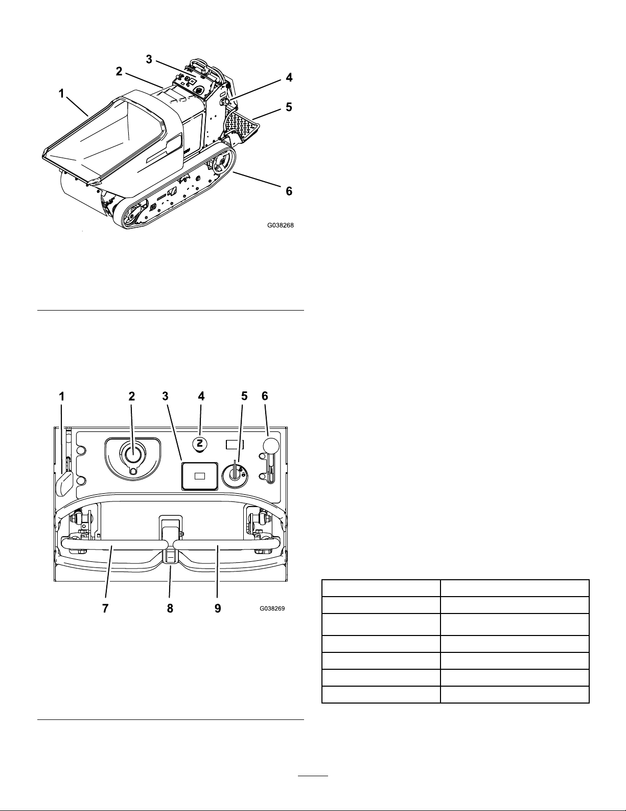
ProductOverview
Figure3
1.Hopper4.Fuel-tankcap
2.Hood
3.Controlpanel
5.Operatorplatform
6.Track
ParkingBrakeLever
Toengagetheparkingbrake,pullbackthelever.(Figure4).
Toreleasetheparkingbrake,pushtheleverforward.
HourMeter
Thehourmeterrecordsthenumberofhourstheenginehas
operated.Itoperateswhentheengineisrunning.Usethese
timesforschedulingregularmaintenance(Figure4).
ChokeControl
Usethechoketostartacoldengine.Pullthechokeknob
uptoengageit.Pushthechokeknobdowntodisengage
g038268
it(Figure4).
KeySwitch
Usethekeyswitchtostarttheengine(Figure4).Theswitch
has3positions:OFF,RUN,andSTART.
ThrottleLever
Controls
Becomefamiliarwithallthecontrols(Figure4)beforeyou
starttheengineandoperatethemachine.
Figure4
ThethrottleleverisvariablebetweentheFASTandSLOW
positions(Figure4).
Motion-ControlLevers
Usethemotion-controlleverstodrivethemachineforward
andreverseandtoturneitherdirection(Figure4).
DumpSwitch
Usethedumpswitchtodumpandlowerthehopper.Ifyou
holdtheswitchdown0.2to1.3seconds,thehopperfully
lowersautomatically .
Specications
Note:Specicationsanddesignaresubjecttochange
withoutnotice.
Width
g038269
Length
Height
90.2cm(35-1/2inches)
268.0cm(105-1/2inches)
121.2cm(47.7inches)
1.Parking-brakelever6.Throttlelever
2.Hydraulic-tankcap
3.Hourmeter8.Dumpswitch
4.Chokecontrol
5.Keyswitch
7.Leftmotion-controllever
9.Rightmotion-controllever
Weight
Hoppercapacity
Maximumload
DischargeHeight
9
734kg(1619lb)
0.45m
1134kg(2,500lb)
38.1cm(15inches)
3
(16ft3)
Page 10

Operation
G009027
1
2
Note:Determinetheleftandrightsidesofthemachine
fromthenormaloperatingposition.
Important:Beforeoperating,checkthefuelandoil
level,andremovedebrisfromthemachine.Also,ensure
thattheareaisclearofpeopleanddebris.Youshould
alsoknowandhavemarkedthelocationsofallutility
lines.
ThinkSafetyFirst
Carefullyreadallsafetyinstructionsandsymbolsinthe
safetysection.Knowingthisinformationcouldhelpyouor
bystandersavoidinjury.
CAUTION
Thismachineproducessoundlevelsthatcancause
hearinglossthroughextendedperiodsofexposure.
Wearhearingprotectionwhenoperatingthis
machine.
Useprotectiveequipmentforyoureyes,ears,hands,feet,
andhead.
DANGER
Incertainconditions,fuelisextremelyammable
andhighlyexplosive.Areorexplosionfromfuel
canburnyouandothersandcandamageproperty.
•Fillthefueltankoutdoors,inanopenarea,when
theengineiscold.Wipeupanyfuelthatspills.
•Neverllthefueltankinsideanenclosedtrailer.
•Donotllthefueltankcompletelyfull.Add
fueltothefueltankuntilthelevelis6to13mm
(1/4to1/2inch)belowthebottomoftheller
neck.Thisemptyspaceinthetankallowsfuel
toexpand.
•Neversmokewhenhandlingfuelandstayaway
fromanopenameorwherefuelfumesmaybe
ignitedbyaspark.
•Storefuelinanapprovedcontainerandkeepit
outofthereachofchildren.Neverbuymore
thana30-daysupplyoffuel.
•Donotoperatewithoutentireexhaustsystemin
placeandinproperworkingcondition.
DANGER
Incertainconditionsduringfueling,static
electricitycanbereleasedcausingaspark,which
canignitethefuelvapors.Areorexplosionfrom
g009027
Figure5
1.Weareyeprotection.2.Wearhearingprotection.
AddingFuel
•Forbestresults,useonlyclean,fresh(lessthan30days
old),unleadedgasolinewithanoctaneratingof87or
higher((R+M)/2ratingmethod).
•ETHANOL:Gasolinewithupto10%ethanol(gasohol)
or15%MTBE(methyltertiarybutylether)byvolume
isacceptable.EthanolandMTBEarenotthesame.
Gasolinewith15%ethanol(E15)byvolumeisnot
approvedforuse.Neverusegasolinethatcontainsmore
than10%ethanolbyvolume,suchasE15(contains15%
ethanol),E20(contains20%ethanol),orE85(contains
upto85%ethanol).Usingunapprovedgasolinemay
causeperformanceproblemsand/orenginedamage
whichmaynotbecoveredunderwarranty.
•Donotusegasolinecontainingmethanol.
•Donotstorefueleitherinthefueltankorfuelcontainers
overthewinterunlessafuelstabilizerisused.
•Donotaddoiltogasoline.
fuelcanburnyouandothersandcandamage
property.
•Alwaysplacefuelcontainersonthegroundaway
fromyourvehiclebeforelling.
•Donotllfuelcontainersinsideavehicleoron
atruckortrailerbedbecauseinteriorcarpets
orplastictruckbedlinersmayinsulatethe
containerandslowthelossofanystaticcharge.
•Whenpractical,removefuel-poweredequipment
fromthetruckortrailerandrefueltheequipment
withitswheelsontheground.
•Ifthisisnotpossible,thenrefuelsuchequipment
onatruckortrailerfromaportablecontainer,
ratherthanfromafuel-dispensernozzle.
•Ifyoumustuseafuel-dispensernozzle,keepthe
nozzleincontactwiththerimofthefueltank
orcontaineropeningatalltimesuntilfuelingis
complete.
10
Page 11
WARNING
Fuelisharmfulorfatalifswallowed.
Long-termexposuretovaporscancause
seriousinjuryandillness.
•Avoidprolongedbreathingofvapors.
•Keepyourfaceawayfromnozzleandfueltank
orconditioneropening.
•Keepfuelawayfromeyesandskin.
UsingStabilizer/Conditioner
Useafuelstabilizer/conditionerinthemachinetoprovide
thefollowingbenets:
•Keepsfuelfreshduringstorageof90daysorless.For
longerstorage,drainthefueltank.
•Cleanstheenginewhileitruns
•Eliminatesgum-likevarnishbuildupinthefuelsystem,
whichcauseshardstarting
Important:Donotusefueladditivescontaining
methanolorethanol.
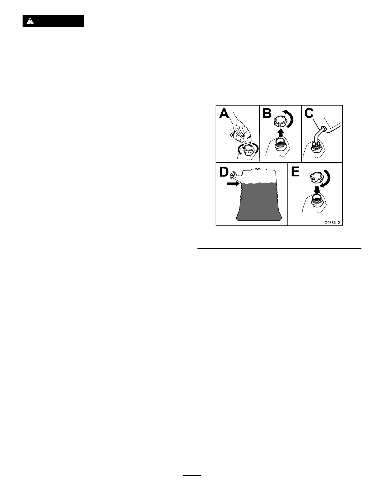
FillingtheFuelTank
Fuel-tankcapacity:40.1L(10.6USgallons)
1.Cleantheareaaroundthefuel-tankcap.
2.Removethecap.
3.Addfueluntilitisatthebottomofthellerneck.
Note:Donotllthefueltankcompletelyfull.The
emptyspaceinthetankallowsthefueltoexpand.
4.Installthecap.
Addthecorrectamountofstabilizer/conditionertothe
fuel.
Note:Afuelstabilizer/conditionerismosteffective
whenmixedwithfreshfuel.Tominimizethechanceof
varnishdepositsinthefuelsystem,usefuelstabilizerat
alltimes.
g038312
Figure6
PerformingDailyMaintenance
Beforestartingtheengineeachday,performthefollowing
procedures:
•Checktheengine-oillevel—refertoCheckingthe
Engine-OilLevel(page19).
•Checkthehydraulic-uidlevelforthedrivesystem—refer
toCheckingtheHydraulic-FluidLevelfortheDrive
System(page30)
•Checkthehydraulic-uidlevelfortheliftsystem—refer
toCheckingtheHydraulic-FluidLevelfortheLiftSystem
(page32).
11
Page 12

OperatingtheParkingBrake
G008946
G008959
1
2
OperatingtheChoke
Alwaysengagetheparkingbrakewhenyoustopthemachine
orleaveitunattended.Beforeeachuse,checktheparking
brakeforproperoperation.
CAUTION
Childrenorbystandersmaybeinjuredifthey
moveorattempttooperatethemachinewhileitis
unattended.
Alwaysremovetheignitionkeyandengage
theparkingbrakewhenleavingthemachine
unattended.
EngagingtheParkingBrake
Pulltheparking-brakeleverrearwardintotheENGAGED
position(Figure7).
Usethechoketostartacoldengine.
1.Pullupthechokeknobtoengagethechokebefore
usingtheignitionswitch(Figure9).
2.Pushdownthechokeknobtodisengagethechoke
aftertheenginehasstarted(Figure9).
g008959
Figure9
Figure7
1.Parkingbrake—engaged2.Parkingbrake—released
g009465
1.Onposition2.Offposition
ReleasingtheParkingBrake
Pushtheparking-brakeleverforward(Figure7).
OperatingtheThrottle
ThethrottlecontrolmovesbetweenFASTandSLOWpositions
(Figure8).
AlwaysusetheFASTpositionwhenmovingthemachine.
g008946
Figure8
12
Page 13

StartingtheEngine
ShuttingOfftheEngine
1.Engagetheparkingbrake.
2.Engagethechoke.
Note:Awarmorhotenginemaynotrequirechoking.
Youmayneedtorepeatthestartingcyclewhenyou
starttheengineforthersttimeafteryouhavelleda
completelyemptyfuelsystemwithfuel.
3.MovethethrottlebetweentheFASTandSLOW
positions.
4.TurnthekeyswitchtotheSTARTposition.
5.Whentheenginestarts,disengagethechoke.
Important:Donotengagethestarterformorethan5
secondsatatime.Iftheenginefailstostart,allowa
15-secondcool-downperiodbetweenattempts.Failure
tofollowtheseinstructionscanburnoutthestarter.
1.MovethethrottlebetweentheFASTandSLOW
positions.
2.Engagetheparkingbrake.
3.TurnthekeyswitchtotheOFFpositionandremove
thekey.
g038314
Figure11
Figure10
OperatingtheHopper
Hoppercapacity:1134kg(2,500lb)
Knowtheloadcapacityofthemachineandneverexceedit.
Thismachinenormallyoperatesonuneven,unpaved,bumpy,
and/orinclinedsurfaces—adjusttheloadaccordingly.
1.Positionthemachinewhereyouintendtodumpthe
load.
2.Dumpthehopperbypushingthetopofthedump
switch(Figure12).
3.Lowerthehopperbypushingthebottomofthedump
switch(Figure12).
g038313
Note:Ifyouholdthebottomoftheswitch0.2to1.3
seconds,thehopperfullylowersautomatically.
Figure12
1.Dumpthehopper.2.Lowerthehopper.
13
g038270
Page 14
RemovingDebrisfromthe
TransportingtheMachine
Machine
1.Parkthemachineonalevelsurface,movethe
motion-controlleverstotheNEUTRAL-LOCKposition,
engagetheparkingbrake,andlowerthehopper.
2.Shutofftheengine,andremovethekey .Allowthe
enginetocool.
3.Cleantheinsideofthehopperusingahose.
4.Cleananydebrisfromunderthehopper.
5.Wipeawaydebrisfromtheaircleaner.
6.Cleananydebrisbuildupontheengineandinthe
transmissionwithabrushorblower.
Important:Itispreferabletoblowdirtout,rather
thanwashingitout.Ifyouusewater,keepitaway
fromelectricalpartsandhydraulicvalves.Do
notuseahigh-pressurewasher.High-pressure
washingcandamagetheelectricalsystemand
hydraulicvalvesordepletegrease.
LoweringtheHopperwithout
Useaheavy-dutytrailerortruckwithfull-widthrampsto
transportthemachine.Ensurethatthetrailerortruckhasall
thenecessarybrakes,lighting,andmarkingasrequiredbylaw .
Pleasecarefullyreadallthesafetyinstructions.Knowingthis
informationcouldhelpyou,yourfamily,petsorbystanders
avoidinjury.Refertoyourlocalordinancesfortrailerand
tie-downrequirements.
Important:Donotoperateordrivethemachineon
roadways.
1.Lowerthehopper.
2.Ifusingatrailer,connectittothetowingvehicleand
connectthesafetychains.
3.Ifapplicable,connectthetrailerbrakes.
4.Carefullyloadthemachineontothetrailerortruck.
5.Shutofftheengine,removethekey ,andsetthebrake.
6.Usethemetaltie-downloopsonthemachineto
securelyfastenthemachinetothetrailerortruckwith
straps,chains,cable,orropes(Figure14).
Power
1.Installthecylinderlock;refertoInstallingtheCylinder
Lock(page17).
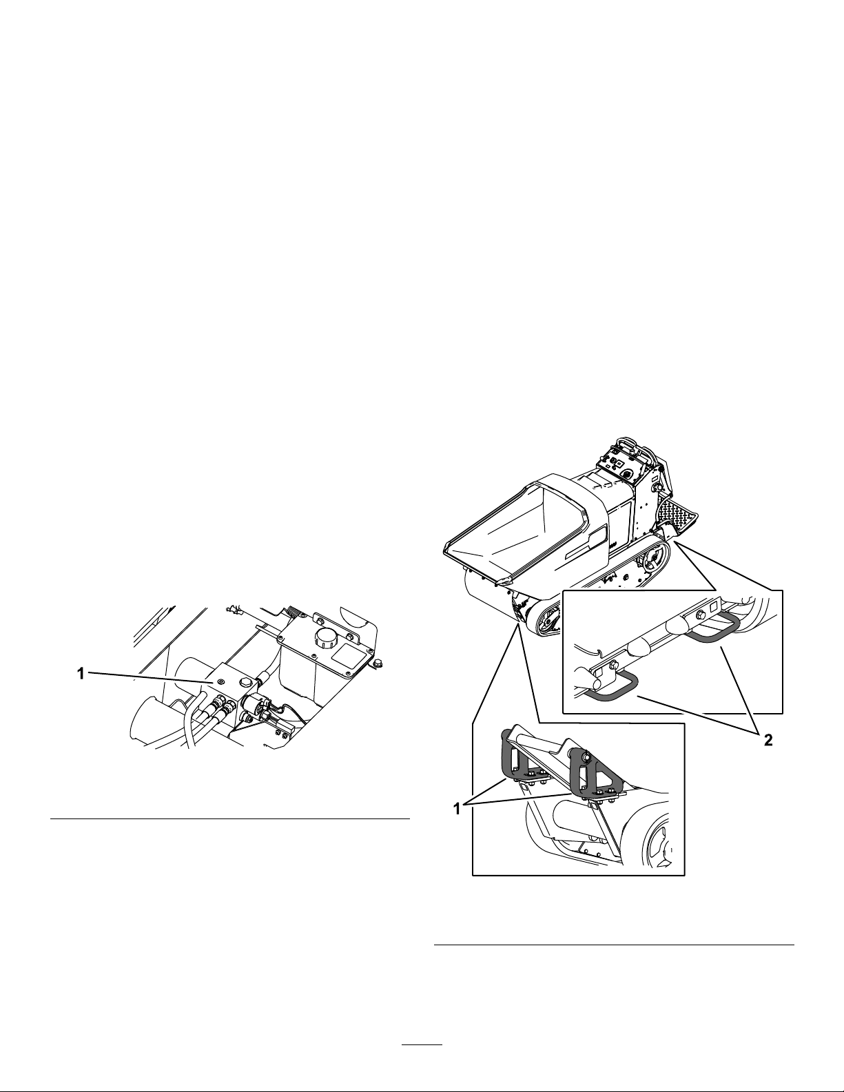
2.Ensurethatthetubisempty.
3.Placealargedrainpanunderthehydraulic-manifold
block(Figure13).
Figure13
1.Hydraulic-manifoldblock
4.Disconnectthehosettingsinthemanifoldblockand
allowtheuidtodrainintothepain.
g186548
Note:Disposeoftheuseduidatacertiedrecycling
center.
5.Connectthehosettings.
6.Useahoistorhave2peopleholdupthehopperand
removethecylinderlock.
7.Carefullylowerthehoppertothemachineframe.
g185890
Figure14
1.Fronttie-downloops2.Reartie-downloops
14
Page 15

LiftingtheMachine
Hoistthemachineusing2liftpointsunderthehopperand
2reartie-downloops.Tiltthehopperforwardtolocatethe
2liftloopsandattachachainorstrapsateachoftheloops
asshowninFigure15.
Note:Takeuptheslackinthechainorstrapstoproperly
balancetheunit.
1.Liftpointsunderhopper
g194436
Figure15
2.Reartie-downloops
15
Page 16

Maintenance
Note:Determinetheleftandrightsidesofthemachinefromthenormaloperatingposition.
RecommendedMaintenanceSchedule(s)
MaintenanceService
Interval
Aftertherst10hours
Beforeeachuseordaily
Every25hours
Every40hours
Every50hours
Every100hours
MaintenanceProcedure
•Checkandadjustthetracktension(every10hoursuntil50hours).
•Checktheengine-oillevel.
•Cleantheblowerhousing(moreoftenunderextremelydusty ,dirtyconditions).
•Checktheconditionofthetrack.
•Checktheparkingbrakeoperation.
•Checkthehydraulic-uidlevelforthedrivesystem.
•Checkthehydraulic-uidlevelfortheliftsystem.
•Removedebrisfromthemachine.
•Checkforloosefasteners.
•Serviceorreplacetheair-cleanerfoamelement(moreoftenunderextremelydusty ,
dirtyconditions).
•Checkthehydrauliclinesforleaks,loosettings,kinkedlines,loosemounting
supports,wear,anddeterioration.
•Greasethemachine(greaseimmediatelyaftereverywashing).
•Checkthebattery.
•Checkandadjustthetracktension.
•Replacetheair-cleanerpaperelement(moreoftenunderextremelydusty,dirty
conditions).
•Changetheengineoilandtheengine-oillter.
•Checkthesparkplug.
•Removethecoolingshroudsandcleanthecoolingareas(moreoftenunder
extremelydusty,dirtyconditions).
•Replacethefuellter(moreoftenunderdusty ,dirtyconditions).
•Inspectthedrivebelt.
•Cleandirtbuildupinthechassis.
•Replacethesparkplug.
•Checktheroadwheels.
Every300hours
•Replacethedrivebelt.
•Changethehydraulicuidandlterforthedrivesystem.
•Changethehydraulicuidfortheliftsystem.
•Replacethehydrauliclterfortheliftsystem.
Important:Refertoyourengineowner'smanualforadditionalmaintenanceprocedures.
16
Page 17

Pre-Maintenance
Procedures
ReleasingtheCushionfor RearAccess
Youcanreleasethecushionforrearaccesstothemachinefor
maintenanceoradjustment.
1.Lowertheplatform.
2.Loosenthetwistknobsoneachsideofthemachine
(Figure16).
Figure16
1.Twistknob
2.Cushion
g185887
Figure17
1.Cylinderlock2.Lift-cylinderrod
4.Slowlylowerthehopperuntilthecylinderlockcontacts
thecylinderbodyandrodend.
g032556
RemovingandStoringtheCylinder
Lock
3.Removethecushionandlowerittotheplatform.
4.Performanymaintenanceoradjustmentonthe
machine.
5.Raisethecushion,andslideitontothepinsonboth
sidesofthemachine.
6.Tightenthetwistknobs.
UsingtheCylinderLock
InstallingtheCylinderLock
1.Parkthemachineonalevelsurface,movethe
motion-controlleverstotheNEUTRAL-LOCKposition,
engagetheparkingbrake,andfullyraisethehopper.
2.Removethe2cotterlesspinssecuringthecylinderlock
tothemachine.
3.Slidethecylinderlockoverthelift-cylinderrodand
securewiththecotterlesspins(Figure17).
Important:Removethecylinderlockfromthe
lift-cylinderrodandfullysecureitinthestorageposition
beforeoperatingthemachine.
1.Startthemachine.
2.Fullyraisethehopper.
3.Shutofftheengine.
4.Removethecotterlesspinssecuringthecylinderlock.
5.Placethecylinderlockonthepostsinsidethemachine
frameandsecurewiththecotterlesspins.
6.Lowerthehopper.
17
Page 18

Lubrication
g019608
EngineMaintenance
GreasingtheMachine
ServiceInterval:Every50hours
Whenoperatingthemachineundernormalconditions,
lubricateallgreasettingsforthebearingsandbushingswith
No.2lithiumgrease.Lubricatethebearingsandbushings
immediatelyaftereverywashing,regardlessoftheinterval
listed.Applyalightcoatingofoilontothecontrolcables.
Cylinderpivots(2)—Figure18
ServicingtheAirCleaner
ServiceInterval:Every25hours—Serviceorreplacethe
air-cleanerfoamelement(moreoften
underextremelydusty,dirtyconditions).
Every100hours—Replacetheair-cleanerpaper
element(moreoftenunderextremelydusty,dirty
conditions).
Note:Operatingtheenginewithlooseordamaged
air-cleanercomponentscouldallowunlteredairintothe
engine,causingprematurewearandfailure.
Note:Servicetheaircleanermoreoftenunderextremely
dusty,dirtyconditions.
RemovingtheElements
1.Rotatethelatchesoutward.
2.Removethecovertoaccesstheair-cleanerelements
(Figure19).
Figure18
g019608
g028105
Figure19
1.Air-cleanercover2.Air-cleanerlatch
3.Removethefoamandpaperelements(Figure20).
4.Removethefoamelementfromthepaperelement
(Figure20).
18
Page 19
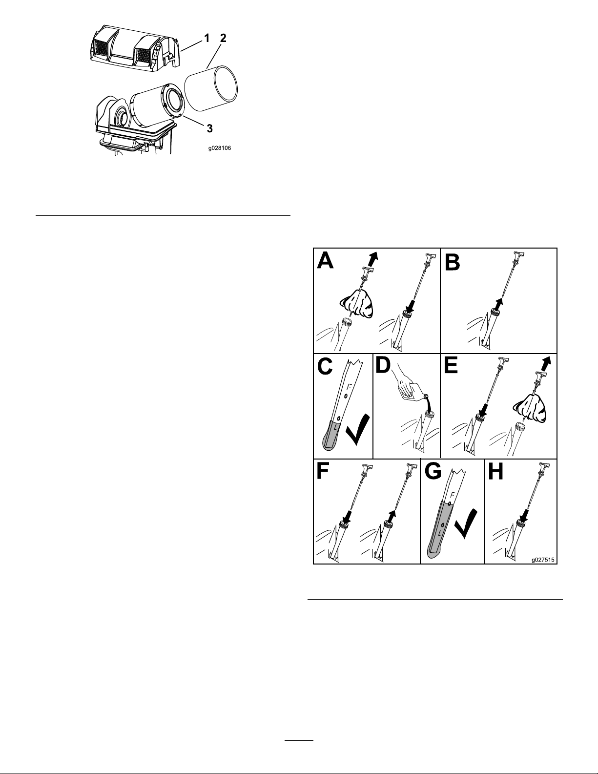
Figure20
B
A
C
D
E
g027515
F
G
H
CheckingtheEngine-OilLevel
ServiceInterval:Beforeeachuseordaily
Important:Remembertoadd80%oftheoil,andthen
graduallyllittotheFullmarkonthedipstick.
Important:Donotruntheenginewiththeoillevel
abovetheFullmarkorbelowthelowmark.Otherwise,
doingsomaydamagetheengine.
1.Parkthemachineonalevelsurface,movethe
g028106
motion-controlleverstotheNEUTRAL-LOCKposition,
engagetheparkingbrake,andlowerthehopper.
1.Air-cleanercover3.Paperelement
2.Foamelement
ServicingtheFoamElement
1.Washthefoamelementinwarmwateranddetergent.
2.Rinseandallowittoairdry.
3.Lightlyoilthefoamelementwithnewoilandsqueeze
outexcessoil.
ServicingthePaperElement
1.Gentlytapthepaperelementtodislodgedirt.
Note:Donotwashthepaperelementoruse
pressurizedair,asthisdamagestheelement.
Note:Replaceadirty,bent,ordamagedelement.
Handlethenewelementcarefully;donotuseifthe
sealingsurfacesarebentordamaged.
2.Cleantheair-cleanerbaseasrequired,andcheckthe
condition.
InstallingtheElements
2.Shutofftheengine,andremovethekey .Allowthe
enginetocool.
3.Openthecowl.
4.Checktheengine-oillevelasshowninFigure21.
1.Installthefoamelementontothepaperelement.
2.Installtheelementsontotheair-cleanerbase(Figure
20).
3.Installthecover,andsecureitwiththelatches(Figure
19).
g027515
Figure21
19
Page 20

ChangingtheEngineOiland
g017552
0
0
50
SAE 30
B
A
C D
E
F
3/4
g027477
Filter
ServiceInterval:Every100hours
OilType::Detergentoil(APIserviceSJorhigher)
EngineOilCapacity:1.9L(2.0USquarts)
Viscosity:Refertothetablebelow .
Figure22
Note:Disposeoftheusedoilatarecyclingcenter.
1.Parkthemachineonalevelsurface,movethe
motion-controlleverstotheNEUTRAL-LOCKposition,
engagetheparkingbrake,raisethehopper,andinstall
thecylinderlock.
g185888
g031623
Figure23
g017552
5.Torquetheplugto13.6N∙m(10ft-lb).
6.Changetheengine-oillterasshowninFigure24.
2.Shutofftheengine,andremovethekey .Allowthe
enginetocool.
3.Startandrunengineforafewminutestowarmthe
engineoil,thenshutofftheengine.
4.ChangetheengineoilasshowninFigure23.
g027477
Figure24
20
Page 21

7.Slowlypourapproximately80%ofthespeciedoil
B
A
C
D
E
g027517
B
A
g027478
B
A
g027479
intothellertube(Figure25).
ServicingtheSparkPlugs
ServiceInterval:Every100hours—Checkthesparkplug.
Every300hours—Replacethesparkplug.
ThesparkplugsareRFIcompliant.Equivalentalternate
brandplugscanalsobeused.
Type:ChampionXC12YC
AirGap:0.76mm(0.03inch)
RemovingtheSparkPlug
1.Parkthemachineonalevelsurface,movethe
motion-controlleverstotheNEUTRAL-LOCKposition,
engagetheparkingbrake,andlowerthehopper.
2.Shutofftheengine,andremovethekey .Allowthe
enginetocool.
3.Beforeremovingthesparkplug(s),cleanthearea
aroundthebaseoftheplugtokeepdirtanddebrisout
oftheengine.
4.Removethesparkplug(Figure26).
g027517
Figure25
g027478
Figure26
CheckingtheSparkPlug
Important:Donotcleanthesparkplug(s).Always
replacethesparkplug(s)whenithas:ablackcoating,
wornelectrodes,anoilylm,orcracks.
Note:Ifyouseelightbrownorgrayontheinsulator,the
engineisoperatingproperly.Ablackcoatingontheinsulator
usuallymeanstheaircleanerisdirty.
Setthegapto0.76mm(0.03inch).
g027479
Figure27
21
Page 22

InstallingtheSparkPlug
B
A
20 ft-lb
27 N-m
g028109
C
D
B
A
C
D
g027753
FuelSystem
Maintenance
ReplacingtheFuelFilter
ServiceInterval:Every100hours/Y early(whichevercomes
rst)(moreoftenunderdusty ,dirty
conditions).
1.Parkthemachineonalevelsurface,movethe
motion-controlleverstotheNEUTRAL-LOCKposition,
engagetheparkingbrake,andlowerthehopper.
2.Shutofftheengine,andremovethekey .Allowthe
enginetocool.
3.ReplacethefuellterasshowninFigure29.
g028109
Figure28
CleaningtheBlowerHousing
Every100hours/Y early(whichevercomesrst)
Toensurepropercooling,ensurethatthegrassscreen,
coolingns,andotherexternalsurfacesoftheengineare
keptcleanatalltimes.
Makesurethecoolingshroudsareinstalled.
Important:Operatingtheenginewithablocked
grassscreen,dirtyorpluggedcoolingns,and/or
coolingshroudsremovedcausesenginedamagedue
tooverheating.
g185888
g027753
Figure29
22
Page 23

DrainingtheFuelTank
RemovingtheFuelTank
Youcandrainthefueltankbyremovingitandpouringthe
fueloutofthellneck;refertoRemovingtheFuelTank
(page23).Youcanalsodrainthefueltankbyusingasiphon
inthefollowingprocedure.
DANGER
Incertainconditions,fuelisextremelyammable
andhighlyexplosive.Areorexplosionfrom
gasolinecanburnyouandothersandcandamage
property.
•Drainfuelfromthefueltankwhentheengineis
cold.Dothisoutdoorsinanopenarea.Wipe
upanyfuelthatspills.
•Neversmokewhendrainingfuelandstayaway
fromanopename,orwhereasparkmayignite
thefuelfumes.
1.Parkthemachineonalevelsurface,movethe
motion-controlleverstotheNEUTRAL-LOCKposition,
engagetheparkingbrake,andlowerthehopper.
2.Shutofftheengine,andremovethekey .Allowthe
enginetocool.
3.Cleanaroundthefuelcaptopreventdebrisfrom
gettingintothefueltank(Figure30).
4.Removethefuelcap.
1.Lowertheplatform.
2.Releasethecushion;refertoReleasingtheCushionfor
RearAccess(page17).
3.Removethecrossbracket(Figure31).
Figure31
1.Fueltank
4.Removethefueltankandsetitontheoperator
platform.
Note:Ifyouwanttomovethefueltankfurtherfrom
themachine,removethefuelandventlinesfromthe
topofthetank.
2.Crossbracket
g186223
5.Insertasyphonpumpintothefueltank.
6.Usingthesyphonpump,drainthefuelintoacleangas
can(Figure30).
7.Wipeupanyspilledfuel.
Figure30
1.Fuelcap
g186224
23
Page 24

ElectricalSystem
Maintenance
ServicingtheBattery
ServiceInterval:Every50hours
WARNING
CALIFORNIA
Proposition65Warning
Batteryposts,terminals,andrelated
accessoriescontainleadandleadcompounds,
chemicalsknowntotheStateofCalifornia
tocausecancerandreproductiveharm.
Washhandsafterhandling.
1.Parkthemachineonalevelsurface,movethe
motion-controlleverstotheNEUTRAL-LOCKposition,
engagetheparkingbrake,andlowerthehopper.
2.Shutofftheengine,andremovethekey .Allowthe
enginetocool.
3.Removethenegativebatterycablefromthebattery
(Figure32).
DANGER
Batteryelectrolytecontainssulfuricacidwhichisa
deadlypoisonandcausessevereburns.
Donotdrinkelectrolyteandavoidcontactwith
skin,eyesorclothing.Wearsafetyglassestoshield
youreyesandrubberglovestoprotectyourhands.
RemovingtheBattery
WARNING
Batteryterminalsormetaltoolscouldshortagainst
metalmachinecomponents,causingsparks.Sparks
cancausethebatterygassestoexplode,resulting
inpersonalinjury.
•Whenremovingorinstallingthebattery,donot
allowthebatteryterminalstotouchanymetal
partsofthemachine.
•Donotallowmetaltoolstoshortbetween
thebatteryterminalsandmetalpartsofthe
machine.
Figure32
1.Positivebatterycable
2.Securingrod
4.Removethepositivebatterycablefromthebattery
(Figure32).
5.Removethe2wingnuts,securingrod,andthebattery
(Figure32).
3.Wingnut(2)
4.Negativebatterycable
InstallingtheBattery
1.Placethebatteryontheplatformandsecureitusing
the2wingnutsandthesecuringrod(Figure32).
2.Installthepositivebatterycabletothebattery(Figure
32).
3.Installthenegativebatterycabletothebattery(Figure
32).
g185906
WARNING
Incorrectbattery-cableroutingcoulddamagethe
machineandcables,causingsparks.Sparkscan
causethebatterygassestoexplode,resultingin
personalinjury.
•Alwaysdisconnectthenegative(black)battery
cablebeforedisconnectingthepositive(red)
cable.
•Alwaysconnectthepositive(red)batterycable
beforeconnectingthenegative(black)cable.
24
Page 25

ChargingtheBattery
ServicingtheFuses
WARNING
Chargingthebatteryproducesgassesthatcan
explode.
Neversmokenearthebatteryandkeepsparksand
amesawayfrombattery.
Important:Alwayskeepthebatteryfullycharged
(1.265specicgravity)topreventbatterydamagewhen
thetemperatureisbelow0°C(32°F).
1.Removethebatteryfromthechassis;refertoRemoving
theBattery(page24).
2.Checktheelectrolytelevel.
3.Ensurethatthellercapsareinstalledonthebattery.
4.Chargethebatteryfor1hourat25to30Aor6hours
at4to6A.
5.Whenthebatteryisfullycharged,unplugthecharger
fromtheelectricaloutlet,anddisconnectthecharger
leadsfromthebatteryposts(Figure33).
6.Installthebatteryontothemachineandconnectthe
batterycables;refertoInstallingtheBattery(page24).
Theelectricalsystemisprotectedbyfusesandrequiresno
maintenance.Ifafuseblows,checkthecomponentorcircuit
foramalfunctionorshort.
1.Releasethecushionfromtherearofthemachine.
2.Pulloutthefusetoremoveorreplaceit(Figure34).
3.Installthecushiontotherearofthemachine.
Note:Ensurethatthecorrect-sizefuseisinstalled
Figure34.
Note:Donotrunthemachinewiththebattery
disconnected;electricaldamagemayoccur.
Figure33
1.Positivebatterypost
2.Negativebatterypost
3.Red(+)chargerlead
4.Black(-)chargerlead
g189366
Figure34
1.Mainpowerfuse(15A)3.Logicfuse(7.5A)
2.Auxiliarypowerfuse(15
A)
g000538
25
Page 26

DriveSystem
Maintenance
ServicingtheTracks
AdjustingtheTrackTension
Ifyouplacethetabofthetensioningtoolalongtherearedge
ofthetensionnut,theotherendofthetensioningtoolshould
alignwiththeedgeofthetensionarmasshowninFigure36.
Ifthedistanceisnotcorrect,adjustthetracktensionusing
thefollowingprocedure:
ServiceInterval:Beforeeachuseordaily—Checkthe
conditionofthetrack.
Aftertherst10hours—Checkandadjustthetrack
tension(every10hoursuntil50hours).
Every50hours—Checkandadjustthetracktension.
Every300hours—Checktheroadwheels.
CleaningtheTracks
1.Parkthemachineonalevelsurface,movethe
motion-controlleverstotheNEUTRAL-LOCKposition,
engagetheparkingbrake,andlowerthehopper.
2.Shutofftheengine,andremovethekey .Allowthe
enginetocool.
3.Lift/supportthesideofthemachinetobeworkedon
sothatthetrackis3to4inches(7.6to10cm)off
theground.
4.Usingawaterhoseorpressurewasher,removedirt
fromeachtracksystem.
Important:Ensurethatyouusehigh-pressurewaterto
washonlythetrackarea.Donotuseahigh-pressure
washertocleantherestofthemachine.Donotuse
highpressurewaterbetweenthedrivesprocketand
themachineoryoumaydamagethemotorseals.
High-pressurewashingcandamagetheelectrical
systemandhydraulicvalvesordepletegrease.
Important:Ensurethatyoufullycleantheroadwheels,
thefrontwheel,andthedrivesprocket(Figure35).The
roadwheelsshouldrotatefreelywhenclean.
Note:Ifthetensioningtoolisnotavailable,thedistance
betweenthenutandedgeofthetensionarmshouldbe7.1
cm(2-13/16inch).
Figure36
LeftTrackShown
1.Tensionnut
2.Tensioningtool(equalto
7.1cmor2-13/16inch)
3.Tensioningbolt7.Tab
4.Bolt(1/4x1-5/8inch)
5.Spacer
6.Nut
8.Tensionarm
1.Parkthemachineonalevelsurface,movethe
motion-controlleverstotheNEUTRAL-LOCKposition,
engagetheparkingbrake,andlowerthehopper.
2.Shutofftheengine,andremovethekey .Allowthe
enginetocool.
3.Cleanthetrackswithhigh-pressurewater.
g202806
Figure35
1.Frontwheel3.Roadwheel
2.Track4.Drivesprocket
Important:Ensurethatyouusehigh-pressure
g186007
watertowashonlythetrackarea.Donotuse
ahigh-pressurewashertocleantherestofthe
machine.Donotusehighpressurewaterbetween
thedrivesprocketandthemachineoryoumay
damagethemotorseals.High-pressurewashing
candamagetheelectricalsystemandhydraulic
valvesordepletegrease.
4.Cleanthedrivesprocket,thefrontwheel,andtheroad
wheels.Theroadwheelsshouldspinfreelywhenclean.
5.Removethebolt(1/4x1-5/8inch),spacer,andnut
(Figure36).
26
Page 27

6.Turnthetensioningbolttoadjustthedistancebetween
thetensionnutandtheendtangentofthetensiontube
untilthedistanceiscorrect,asshowninFigure36)
7.Aligntheclosestnotchinthetensioningbolttothe
boltholeandsecurethetensioningboltwiththebolt
(1/4x1-5/8inch),spacer,andnut(Figure36).
ReplacingtheTracks
ServicingtheDriveBelt
InspectingtheDriveBelt
ServiceInterval:Every100hours
1.Parkthemachineonalevelsurface,movethe
motion-controlleverstotheNEUTRAL-LOCKposition,
engagetheparkingbrake,andlowerthehopper.
Replacethetrackswhentheyarebadlyworn.
1.Parkthemachineonalevelsurface,movethe
motion-controlleverstotheNEUTRAL-LOCKposition,
engagetheparkingbrake,andlowerthehopper.
2.Shutofftheengine,andremovethekey .Allowthe
enginetocool.
3.Lift/supportthesideofthemachinetobeworkedon
sothatthetrackis3to4inches(7.6to10cm)off
theground.
4.Removetheretainingboltforthetensioningscrew .
5.Releasethedrivetensionbyturningthetensioning
screwclockwise(Figure36andFigure37).
Figure37
1.Frontwheel4.Roadwheel
2.Track5.Drivesprocket
3.Tensioningscrewand
retainingbolt
6.Removethetrackatthetopofthefrontwheel,peeling
itoffthewheelwhilerotatingthetrackforwards.
7.Whenthetrackisoffthefrontwheel,removeitfrom
thedrivesprocketandroadwheels(Figure37).
8.Beginningatthedrivesprocket,coilthenewtrack
aroundthesprocket,ensuringthatthelugsonthetrack
tbetweenthespacersonthesprocket(Figure37).
9.Pushthetrackunderthelugsandbetweentheroad
wheels(Figure37).
10.Startingatthebottomofthefrontwheel,installthe
trackaroundthewheelbyrotatingthetrackrearward
whilepushingthelugsintothewheel.
11.Tensionthetrack;refertoAdjustingtheTrackTension
(page26).
12.Lowerthemachinetotheground.
2.Shutofftheengine,andremovethekey .Allowthe
enginetocool.
3.Releasethecushionandremovethefueltank;referto
RemovingtheFuelTank(page23).
4.Inspectthebelt(Figure38).Replacethebeltifitis
worn;refertoReplacingtheDriveBelt(page27).
Note:Thesignsofawornbeltincludesquealing
whilethebeltisrotating,frayededges,burnmarks,and
cracksonthebelt.
g189546
Figure38
1.Extensionspring2.Belt
ReplacingtheDriveBelt
ServiceInterval:Every300hours
1.Parkthemachineonalevelsurface,movethe
motion-controlleverstotheNEUTRAL-LOCKposition,
engagetheparkingbrake,andlowerthehopper.
2.Shutofftheengine,andremovethekey .Allowthe
enginetocool.
3.Releasethecushionandremovethefueltank;referto
RemovingtheFuelTank(page23).
4.Raisetherearofthemachineandsupportthemachine
onjackstands.
5.Removetheextensionspring(Figure38).
6.Removethe2bolts,2nuts,andgearpumpfromthe
pumpmount(Figure39).
Note:Youdonotneedtoremovethettingsfrom
thepump.
13.Repeatsteps3through12toreplacetheothertrack.
27
Page 28
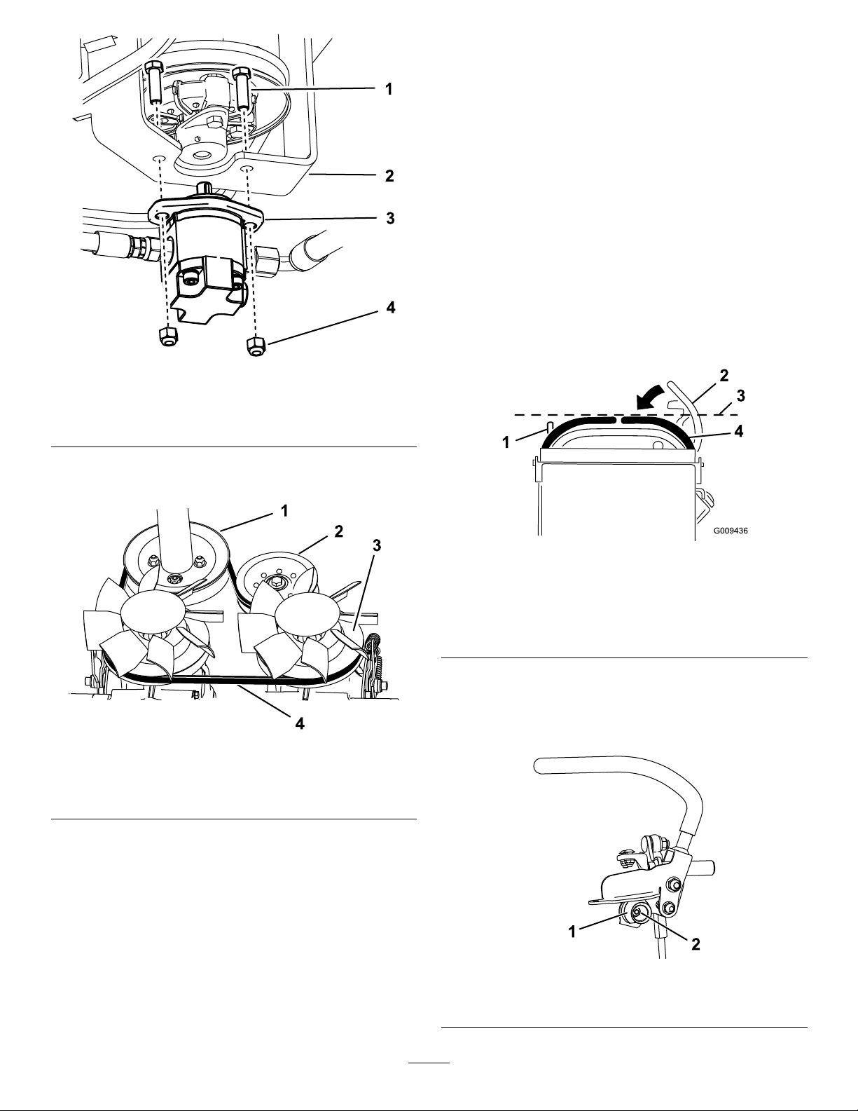
Figure39
1.Bolt(2)3.Gearpump
2.Pumpmount
4.Nut(2)
ControlsSystem
Maintenance
AdjustingtheMotion-Control Levers
Ifthemotion-controlleversdonotalignhorizontally,adjust
therightsidemotion-controllever.
1.Parkthemachineonalevelsurface,lowerthehopper,
engagetheparkingbrake,shutofftheengine,and
removethekey .
2.Pushthemotion-controlleversdownoutofthe
NEUTRAL-LOCKposition(Figure41).
3.Checkiftherightmotion-controlleveraligns
horizontallywiththeleftmotion-controllever(Figure
g189559
41).
7.Removethedrivebeltfromtheenginepulleyand2
transmissionpulleys
Figure40
1.Enginepulley
2.Idlerpulley4.Belt
3.Transmissionpulley(2)
8.Routethenewbeltaroundtheenginepulleyand2
transmissionpulleys(Figure40).
g009436
Figure41
1.Leftmotion-controllever3.Checkthehorizontal
2.Rightmotion-controllever
intheNeutral-lockposition
alignmenthere
4.Rightmotion-controllever
4.Toadjustthemotion-controllevershorizontally,you
mustadjustthecam.
5.Releasethecushionfromtherearofthemachine.
g189571
6.Loosenthenutholdingthecam(Figure42).
9.Installthegearpump(Figure39).
10.Installtheextensionspring(Figure38).
11.Installthefueltank;refertoRemovingtheFuelTank
(page23).
12.Raisethecushion.
g189389
Figure42
1.Cam
28
2.Nut
Page 29

7.Adjustthecamuntilitalignswiththeleft
motion-controlleverandtightenthenutforthecam.
Note:Movingthecamclockwise(inthevertical
position)lowersthehandle;movingthecam
counterclockwise(intheverticalposition)raisesthe
handle.
Important:Ensurethattheatportionofthe
camdoesnotgoaboveaverticalposition(rightor
left);otherwiseyoumaydamagetheswitch.
8.Repeatsteps2through7fortheleftmotion-control
lever.
BrakeMaintenance
WARNING
Ifthebrakesarenotproperlyadjusted,serious
injury,ordeath,mayoccur.
Checkyourbrakesdaily.Ifyouencounterany
problemswiththebrakeswhileoperatingthe
machine,stopthemachineimmediatelyandbring
ittoanAuthorizedToroServiceDealerforrepair.
AdjustingtheParkingBrake
1.Removethefueltank;refertoRemovingtheFuelTank
(page23).
2.Insidetheleftsideofthecontroltower,adjustthenuts
untilthecablesaretaught(Figure43).
Figure43
1.Cable
2.Nuts
CheckingtheParkingBrake
ServiceInterval:Beforeeachuseordaily
1.Parkthemachineonalevelsurface,lowerthehopper,
andengagetheparkingbrake.
2.Starttheengineandmovethethrottlelevertothe
FASTposition.
3.Movethemotion-controlleversforward.
Note:Themachineshouldnotmoveforward.
Note:Ifthemachinemovesforward,referto
AdjustingtheParkingBrake(page29).
4.Releasetheparkingbrake.
5.Movethemotion-controlleversforward.
Note:Themachineshouldmoveforward.
Note:Ifthemachinedoesnotmoveforward,referto
AdjustingtheParkingBrake(page29).
6.Engagetheparkingbrakeandshutoffthemachine.
3.Installthefueltank,crossbracket,andcushion.
29
Page 30

HydraulicSystem
Maintenance
WARNING
Hydraulicuidescapingunderpressurecan
penetrateskinandcauseinjury.Fluidinjectedinto
theskinmustbesurgicallyremovedwithinafew
hoursbyadoctorfamiliarwiththisformofinjury
organgrenemayresult.
•Keepyourbodyandhandsawayfrompin
holeleaksornozzlesthatejecthighpressure
hydraulicuid.
•Usecardboardorpapertondhydraulicleaks;
neveruseyourhands.
ServicingtheHydraulicDrive System
Expansion-tankcapacity:1.4L(1.5USquarts)
Figure44
1.Expansion-tankcap
2.Sightwindow
5.Iftheoillevelislow ,removethecaplockandcap
fromthetopoftheexpansiontank(Figure45),and
addenoughofthespeciedhydraulicuidtoraiseit
totheproperlevel.
3.Fluidatllline
g203616
Hydraulic-uidtype:Toro®HYPR-OIL™500
Important:Alwaysusethecorrecthydraulicuid.
Unspecieduidswilldamagethehydraulicsystem.
Note:Manyhydraulicuidsarealmostcolorless,makingit
difculttospotleaks.Areddyeadditiveforthehydraulic
systemoilisavailablein2/3oz.(20ml)bottles.Onebottle
issufcientfor4-6gal(15-221)ofhydraulicoil.Orderpart
number44-2500fromyourauthorizedT orodistributor.
CheckingtheHydraulic-FluidLevelfor
theDriveSystem
ServiceInterval:Beforeeachuseordaily
1.Parkthemachineonalevelsurface,movethe
motion-controlleverstotheNEUTRAL-LOCKposition,
engagetheparkingbrake,andlowerthehopper.
2.Shutofftheengine,andremovethekey .Allowthe
enginetocool.
3.Openthecowl.
4.Usethesightwindowtochecktheuidlevelinthe
expansiontank(Figure44).
Note:Theuidlevelshouldbeatthelllineonthe
decal.
Figure45
1.Bolt
2.Caplock
6.Installthecapandcaplock.Wipeupanyspilled
hydraulicuid.
3.Cap
ChangingtheHydraulicFluidandFilter
fortheDriveSystem
ServiceInterval:Every300hours
1.Parkthemachineonalevelsurface,movethe
motion-controlleverstotheNEUTRAL-LOCKposition,
engagetheparkingbrake,andlowerthehopper.
2.Shutofftheengine,andremovethekey .Allowthe
enginetocool.
3.Lowerthecushionandremovethefueltank;referto
RemovingtheFuelTank(page23).
4.Removethe6bolts(2rear,4side)fromtheskidplate
andremovetheskidplate(Figure46).
30
Page 31

Figure46
1.Rearbolt(2)3.Sidebolt(4)
2.Skidplate
5.Locatethedrainpluginthebottomofeach
transmission,thenplaceadrainpanundertheplugs
(Figure47).
g203662
g203517
Figure48
1.Ventplug
11.Slowlyaddapproximately6.2L(208oz)uidtothe
expansiontankuntilitstartstocomeoutofthevent
plugs.
Important:UsetheuidspeciedinServicingthe
HydraulicDriveSystem(page30)orequivalent.
Otheruidscouldcausesystemdamage.
Important:Monitorthelevelofuidinthe
expansiontanksothatyoudonotoverllit.
12.Tightentheventplugs.
13.Addhydraulicuidtotheexpansiontankuntilit
reachestheuidline(Figure44).
Important:Donotoverll.
14.Installtheexpansion-tankcap.
Figure47
1.Hydrauliclter
2.Drainplug
6.Removethedrainplugsandallowthehydraulicuidto
fullydrainfromthemachine.
7.Removethehydraulic-ltercapandhydrauliclter
fromeachtransmission(Figure47).
8.Installanewhydrauliclterwiththespringsidefacing
outandthehydraulic-ltercapforeachtransmission.
Torqueto13to15N∙m(115to135in-lb).
9.Installthedrainplugs.
10.Loosentheventplugineachtransmissionuntilloose
(Figure48).
Note:Thisallowsairtoescapethehydraulicsystem
asyouaddhydraulicuid.
g203515
15.Installtheskidplate(Figure46).
16.Installthefueltank;refertoRemovingtheFuelTank
(page23).
17.Starttheengineandletitrunforabout2minutesto
purgeairfromthesystem.
18.Shutofftheengineandcheckforleaks.
31
Page 32

BleedingtheHydraulicDriveSystem
ServicingtheHydraulicLift
Bleedthetractionhydraulicsystemwheneveryouperform
maintenanceonthehydrostatictransmissionoraddhydraulic
uidtotheexpansiontank.
1.Parkthemachineonalevelsurface,movethe
motion-controlleverstotheNEUTRAL-LOCKposition,
engagetheparkingbrake,andlowerthehopper.
2.Shutofftheengine,andremovethekey .Allowthe
enginetocool.
3.Checkthehydraulicuidlevelandaddhydraulicuid
asnecessary;refertoCheckingtheHydraulic-Fluid
LevelfortheDriveSystem(page30).
4.Supportthemachineonjackstands,highenoughto
raisethetracksofftheground.
5.Startthemachine.Slowlymovethemotion-control
leversforwardandreverse5to6times.
6.Checkthehydraulicuidlevelandaddhydraulicuid
asnecessary.
7.Repeatsteps5and6asnecessaryuntilalltheairis
completelypurgedfromthesystem.
Note:Purgingiscompletewhenyouobtainnormal
forwardandreversespeed.
8.Lowerthemachineandrepeattheprocedurewiththe
tracksontheground.
System
CheckingtheHydraulic-FluidLevelfor
theLiftSystem
ServiceInterval:Beforeeachuseordaily
Reservoir-tankcapacity:1.4L(1.5USquarts)
Hydraulic-uidtype:ToroPremiumAllSeasonHydraulic
FluidorMobil®424HydraulicFluid
Important:Alwaysusethecorrecthydraulicuid.
Unspecieduidswilldamagethehydraulicsystem.
Note:Manyhydraulicuidsarealmostcolorless,makingit
difculttospotleaks.Areddyeadditiveforthehydraulic
systemoilisavailablein2/3oz.(20ml)bottles.Onebottle
issufcientfor4-6gal(15-221)ofhydraulicoil.Orderpart
number44-2500fromyourauthorizedT orodistributor.
1.Parkthemachineonalevelsurface,movethe
motion-controlleverstotheNEUTRAL-LOCKposition,
engagetheparkingbrake,raisethehopper,andinstall
thecylinderlock.
2.Shutoffthemachineandremovethekey.Allowthe
machinetocoolcompletely.
3.Removethellercapfromthereservoirtank(Figure
49).
CAUTION
Thehydraulicbreather/llercapisdesigned
topressurizethereservoirto34kPa(5psi).
Loosenthecapslowlytoavoidinjurywhenever
addingoilorworkingonthehydraulicsystem.
Useawrenchonthehexdirectlyunderthe
cap.
32
Page 33

g019614
1
2
Figure49
1.Hex2.Fillercap
4.Lookinsidethetanktochecktheuidlevel.
Note:Ifthemachineiscool,theuidshouldbeat
theCOLDlevel;ifthemachineishot,theuidshould
beattheHOTlevel.
ChangingtheHydraulicFluidforthe
LiftSystem
ServiceInterval:Every300hours
1.Parkthemachineonalevelsurface,movethe
motion-controlleverstotheNEUTRAL-LOCKposition,
engagetheparkingbrake,raisethehopper,andinstall
g185888
thecylinderlock.
2.Shutoffthemachineandremovethekey.Allowthe
machinetocoolcompletely.
3.Removethellercapfromthereservoirtank(Figure
49).
CAUTION
Thehydraulicbreather/llercapisdesigned
topressurizethereservoirto34kPa(5psi).
Loosenthecapslowlytoavoidinjurywhenever
g019614
addingoilorworkingonthehydraulicsystem.
Useawrenchonthehexdirectlyunderthe
cap.
4.Placealargedrainpanunderthettingsatthebottom
ofthereservoirtank.
5.Disconnectahosettingandallowtheuidtodrain
intothepan.
6.Whennished,installandtightenthetting.
Note:Disposeoftheuseduidatacertiedrecycling
center.
7.Fillthereservoirtankwithapproximately2.2L(2.3US
quarts)andinstallthellercap.
8.Removethecylinderlock.
9.Starttheengine.Raiseandlowerthehopper3timesto
llthecylinderandhoseswithuid.
10.Raisethehopperandinstallthecylinderlock.
11.Shutofftheengine.
12.Add0.60L(20oz)ofhydraulicuidandinstallthe
llercap.
Figure50
1.HOTlevel2.COLDlevel
5.FillthetankwithhydraulicuidonlyuptotheCOLD
level.
6.Installthellcap.Wipeupanyspilledhydraulicuid.
7.Removethecylinderlockandlowerthehopper.
Note:TheuidlevelshouldbeattheColdllline.
Donotllpastthisline.
13.Removethecylinderlock.
14.Starttheengine.Raiseandlowerthehopperseveral
g189403
timestoremoveairfromthesystem.
ReplacingtheHydraulicFilterforthe
LiftSystem
ServiceInterval:Every300hours
Important:Donotsubstituteanautomotiveoillteror
severehydraulicsystemdamagemayresult.
1.Parkthemachineonalevelsurface,movethe
motion-controlleverstotheNEUTRAL-LOCKposition,
33
Page 34

engagetheparkingbrake,raisethehopper,andinstall
B
A
C D
E
F
3/4
g027477
thecylinderlock.
2.Shutofftheengine,andremovethekey .Allowthe
enginetocool.
3.ReplacethelterasshowninFigure51.
CheckingtheHydraulicLines
ServiceInterval:Every40hours—Checkthehydrauliclines
forleaks,loosettings,kinkedlines,
loosemountingsupports,wear,and
deterioration.(Makenecessaryrepairs
beforeoperating.)
WARNING
Hydraulicuidescapingunderpressurecan
penetrateskinandcauseinjury.Fluidinjectedinto
theskinmustbesurgicallyremovedwithinafew
hoursbyadoctorfamiliarwiththisformofinjury;
otherwise,gangrenemayresult.
g186042
•Keepyourbodyandhandsawayfrompinhole
leaksornozzlesthatejecthigh-pressure
hydraulicuid.
•Usecardboardorpapertondhydraulicleaks;
neveruseyourhands.
4.Starttheengineandletitrunforabout2minutesto
purgeairfromthesystem.
5.Shutofftheengineandcheckforleaks.
6.Checktheuidlevelinthereservoirtank,referto
CheckingtheHydraulic-FluidLevelfortheLiftSystem
7.Removethecylinderlockandlowerthehopper.
(page32).
Note:Donotoverllthereservoirtank.
Figure51
g027477
34
Page 35

Cleaning
RemovingDebrisfromthe Machine
ServiceInterval:Beforeeachuseordaily
Every100hours
1.Parkthemachineonalevelsurface,movethe
motion-controlleverstotheNEUTRAL-LOCKposition,
engagetheparkingbrake,andlowerthehopper.
2.Shutofftheengine,andremovethekey .Allowthe
enginetocool.
3.Cleantheinsideofthehopperusingahose.
4.Cleananydebrisfromunderthehopper.
5.Wipeawaydebrisfromtheaircleaner.
6.Cleananydebrisbuildupontheengineandinthe
transmissionwithabrushorblower.
Important:Itispreferabletoblowdirtout,rather
thanwashingitout.Ifyouusewater,keepitaway
fromelectricalpartsandhydraulicvalves.Do
notuseahigh-pressurewasher.High-pressure
washingcandamagetheelectricalsystemand
hydraulicvalvesordepletegrease.
Storage
1.Shutofftheengineandengagetheparkingbrake.
2.Removedirtandgrimefromtheexternalpartsofthe
entiremachine,especiallytheengine.Cleandirtand
chafffromtheoutsideoftheenginecylinderheadns
andblowerhousing.
3.Servicetheaircleaner;refertoServicingtheAir
Cleaner(page18).
4.Greasethemachine;refertoGreasingtheMachine
(page18).
5.Changetheenginecrankcaseoil;refertoChangingthe
EngineOilandFilter(page20).
6.Forstorageover30days,preparethemachineas
follows:
A.Addapetroleumbasedstabilizer/conditioner
tofuelinthetank.Followmixinginstructions
fromstabilizermanufacturer.Donotuse
analcohol-basedstabilizer(ethanolor
methanol).
Note:Fuelstabilizer/conditionerismost
effectivewhenmixedwithfreshfuelandusedat
alltimes.
B.Runtheenginetodistributeconditionedfuel
throughthefuelsystem(5minutes).
C.Shutofftheengine,allowittocool,anddrainthe
fueltankusingapump-typesyphon.
D.Starttheengineandrunituntilitstops.
E.Choketheengine.
F.Startandruntheengineuntilitdoesnotstart
again.
G.Disposeoffuelproperly .Recycleasperlocal
codes.
Important:Donotstorestabilizer/conditioned
fuelover90days.
7.Removethesparkplugsandchecktheconditionof
them;refertoServicingtheSparkPlugs(page21).
8.Preparetheengineasfollows:
A.Withthesparkplugsremovedfromtheengine,
pour2tablespoonsofengineoilintothespark
plugholes.
B.Placearagoverthesparkplugholestocatchany
oilspray ,thenpullthestarterropetocrankthe
engineanddistributetheoilinsidethecylinder.
C.Installthesparkplugs.
Note:Donotinstallthewireonthesparkplugs.
9.Checkandtightenallbolts,nuts,andscrews.Repairor
replaceanypartthatisdamaged.
10.Paintallscratchedorbaremetalsurfaces.Paintis
availablefromyourAuthorizedServiceDealer.
35
Page 36

11.Storethemachineinaclean,drygarageorstoragearea.
12.Coverthemachinetoprotectitandkeepitclean.
36
Page 37

Notes:
Page 38

Notes:
Page 39

Notes:
Page 40

TheToroWarranty
Alimitedwarranty(seewarrantyperiodsbelow)
Concrete,Masonry ,
andCompaction
Equipment
ConditionsandProductsCovered
TheT oroCompanyanditsafliate,T oroWarrantyCompany,pursuanttoanagreement
betweenthem,jointlywarrantyourT oroConcrete,Masonry,andCompaction
EquipmentProductslistedbelowtobefreefromdefectsinmaterialsorworkmanship.
Thiswarrantycoversthecostofpartsandlabor ,butyoumustpaytransportationcosts.
Thefollowingtimeperiodsapplyfromtheoriginaldateofpurchase:
ProductsWarrantyPeriod
ConcreteMixers
•SpindleBearingsLifetime*
1
•Engine
MortarMixers1year
•DrumBearingsandSealsLifetime*
1
•Engine
ForwardPlateCompactors
2
•Engine
ReversiblePlates1year
1
•Engine
RammerCompactors
1
•Engine
MudBuggy1year
1
•Engine
PowerT rowels1year
1
•Engine
Whereawarrantableconditionexists,wewillrepairtheProductatnocosttoyouincludingdiagnosis,
labor,andparts.
*
LifetimeWarranty-OriginalOwnerOnly-Ifthebearing(s)orseal(s)onyourmixerfail,itwillbe
replacedunderwarranty ,atnocostforpartsorlabor.
1
SomeenginesusedonToroProductsarewarrantedbytheenginemanufacturer.
1year
2years
2years
2years
2years
2years
2years
2years
2years
2years
InstructionsforObtainingWarrantyService
IfyouthinkthatyourT oroProductcontainsadefectinmaterialsorworkmanship,
followthisprocedure
1.ContactanyAuthorizedServicingOutlettoarrangeserviceattheirdealership.
Tolocateoneconvenienttoyou,accessourwebsiteatwww.Toro.com.Select
“WheretoBuy”andselect“Contractor”underproducttype.Y oumayalsocall
ourtollfreenumberbelow.
2.Bringtheproductandyourproofofpurchase(salesreceipt)tothem.
3.IfforanyreasonyouaredissatisedwiththeServiceOutlet’sanalysisorwith
theassistanceprovided,contactusat:
ToroWarrantyCompany
SWSCustomerCareDepartment
811 1LyndaleAvenueSouth
Bloomington,MN55420-1 196
TollFree:800-888-9926
**
ToroAuthorizedRentalCustomerswhohavepurchasedproductsdirectlyfromToroandhave
signedtheT oroRentalCustomerAgreementhavetheabilitytoperformtheirownwarrantywork.
PleasevisitT oro’sRentalPortalforelectronicwarrantyclamlingproceduresorcallthetollfree
numberabove.
**
:
OwnerResponsibilities
YoumustmaintainyourToroProductbyfollowingthemaintenanceprocedures
describedintheOperator’sManual.Suchroutinemaintenance,whetherperformedby
adealerorbyyou,isatyourexpense.Partsscheduledforreplacementasrequired
maintenance(“MaintenanceParts”),arewarrantedfortheperiodoftimeuptothe
scheduledreplacementtimeforthatpart.Failuretoperformrequiredmaintenance
andadjustmentscanbegroundsfordisallowingawarrantyclaim.
ItemsandConditionsNotCovered
Notallproductfailuresormalfunctionsthatoccurduringthewarrantyperiodare
defectsinmaterialsorworkmanship.Thisexpresswarrantydoesnotcoverthe
following:
•Productfailureswhichresultfromtheuseofnon-T ororeplacementparts,orfrom
installationanduseofadd-on,modied,orunapprovedaccessories
•Productfailureswhichresultfromfailuretoperformrequiredmaintenanceand/or
adjustments
•Productfailureswhichresultfromoperatingtheproductinanabusive,negligent,
orrecklessmanner
•Partssubjecttoconsumptionthroughuseunlessfoundtobedefective.
Examplesofpartswhichareconsumed,orusedup,duringnormalproduct
operationinclude,butarenotlimitedto:belts,wipers,sparkplugs,tires,lters,
gaskets,wearplates,seals,O-rings,drivechains,orclutches.
•Failurescausedbyoutsideinuence.Itemsconsideredtobeoutsideinuence
include,butarenotlimitedto,weather,storagepractices,contamination,useof
unapprovedcoolants,lubricants,additives,orchemicals,etc.
•Normal“wearandtear”items.Normal“wearandtear”includes,butisnotlimited
to,wornpaintedsurfaces,scratcheddecals,etc.
•Repairsnecessaryduetofailuretofollowrecommendedfuelprocedure(consult
Operator'sManualformoredetails)
–Removingcontaminantsfromthefuelsystemisnotcovered
–Useofoldfuel(morethanonemonthold)orfuelwhichcontainsmorethan
10%ethanolormorethat15%MTBE
–Failuretodrainthefuelsystempriortoanyperiodofnon-useoverone
month
•Anycomponentcoveredbyaseparatemanufacturer’swarranty
•Pickupanddeliverycharges
GeneralConditions
RepairbyanAuthorizedServicingOutletorSelf-ServiceasanAuthorizedRental
Customerisyoursoleremedyunderthewarranty .
NeitherTheToroCompanynorToroWarrantyCompanyisliableforindirect,
incidentalorconsequentialdamagesinconnectionwiththeuseoftheToro
Productscoveredbythiswarranty,includinganycostorexpenseofproviding
substituteequipmentorserviceduringreasonableperiodsofmalfunction
ornon-usependingcompletionofrepairsunderthiswarranty .Allimplied
warrantiesofmerchantabilityandtnessforusearelimitedtothedurationof
thisexpresswarranty .Somestatesdonotallowexclusionsofincidentalor
consequentialdamages,orlimitationsonhowlonganimpliedwarrantylasts,
sotheaboveexclusionsandlimitationsmaynotapplytoyou.
Thiswarrantygivesyouspeciclegalrights,andyoumayalsohaveotherrights
whichvaryfromstatetostate.
ExceptfortheenginewarrantycoverageandtheEmissionswarrantyreferenced
below,ifapplicable,thereisnootherexpresswarranty .TheEmissionsControlSystem
onyourProductmaybecoveredbyaseparatewarrantymeetingrequirements
establishedbytheU.S.EnvironmentalProtectionAgency(EPA)ortheCalifornia
AirResourcesBoard(CARB).RefertotheCaliforniaEmissionControlWarranty
StatementsuppliedwithyourProductorcontainedintheenginemanufacturer’s
documentationfordetails.
CountriesOtherthantheUnitedStatesorCanada
CustomerswhohavepurchasedT oroproductsoutsidetheUnitedStatesorCanadashouldcontacttheirT oroDistributor(Dealer)toobtainguaranteepoliciesforyourcountry ,
province,orstate.IfforanyreasonyouaredissatisedwithyourDistributor'sserviceorhavedifcultyobtainingguaranteeinformation,contacttheToroimporter.Ifallother
remediesfail,youmaycontactusatT oroWarrantyCompany.
AustralianConsumerLaw:AustraliancustomerswillnddetailsrelatingtotheAustralianConsumerLaweitherinsidetheboxoratyourlocalT oroDealer .
374-0288RevD
 Loading...