

Page 1

Consumer Products
LX Lawn
Tractor
Service Manual
Page 2

Page 3

TABLE OF CONTENTS
SAFETY INFORMATION
General Information . . . . . . . . . . . . . . . . . . . . . . . . . . . . . . . . . .
Think Safety First . . . . . . . . . . . . . . . . . . . . . . . . . . . . . . . . . . .
SPECIFICATIONS
Torque Specifi cations . . . . . . . . . . . . . . . . . . . . . . . . . . . . . . . . .
Standard Torque for Dry, Zinc Plated and Steel Fasteners (Inch Series) . . . . . . . . . . . . . .
Standard Torque for Dry, Zinc and Steel Fasteners (Metric Fasteners) . . . . . . . . . . . . . .
Other Torque Specifi cations . . . . . . . . . . . . . . . . . . . . . . . . . . . . . . .
Equivalents and Conversions . . . . . . . . . . . . . . . . . . . . . . . . . . . . . .
Product Specifi cations . . . . . . . . . . . . . . . . . . . . . . . . . . . . . . . . .
CHASSIS
Front Pivot Axle Replacement
Removal . . . . . . . . . . . . . . . . . . . . . . . . . . . . . . . . . . . . .
Installation . . . . . . . . . . . . . . . . . . . . . . . . . . . . . . . . . . . .
Axle Assembly Replacement
Removal . . . . . . . . . . . . . . . . . . . . . . . . . . . . . . . . . . . . .
Installation . . . . . . . . . . . . . . . . . . . . . . . . . . . . . . . . . . . .
Steering Wheel Replacement
Removal . . . . . . . . . . . . . . . . . . . . . . . . . . . . . . . . . . . . .
Installation . . . . . . . . . . . . . . . . . . . . . . . . . . . . . . . . . . . .
Steering Shaft Replacement
Removal . . . . . . . . . . . . . . . . . . . . . . . . . . . . . . . . . . . . .
Installation . . . . . . . . . . . . . . . . . . . . . . . . . . . . . . . . . . . .
Electric PTO Clutch Replacement
Removal . . . . . . . . . . . . . . . . . . . . . . . . . . . . . . . . . . . . .
Installation . . . . . . . . . . . . . . . . . . . . . . . . . . . . . . . . . . . .
Fuel Tank Replacement
Removal . . . . . . . . . . . . . . . . . . . . . . . . . . . . . . . . . . . . .
Installation . . . . . . . . . . . . . . . . . . . . . . . . . . . . . . . . . . . .
Hood Replacement
Removal . . . . . . . . . . . . . . . . . . . . . . . . . . . . . . . . . . . . .
Installation . . . . . . . . . . . . . . . . . . . . . . . . . . . . . . . . . . . .
Fender Replacement
Removal . . . . . . . . . . . . . . . . . . . . . . . . . . . . . . . . . . . . .
Installation . . . . . . . . . . . . . . . . . . . . . . . . . . . . . . . . . . . .
Tower Replacement
Removal . . . . . . . . . . . . . . . . . . . . . . . . . . . . . . . . . . . . .
Installation . . . . . . . . . . . . . . . . . . . . . . . . . . . . . . . . . . . .
Lower Transmission Drive Belt Replacement - Gear Drive Models
Removal . . . . . . . . . . . . . . . . . . . . . . . . . . . . . . . . . . . . .
Installation . . . . . . . . . . . . . . . . . . . . . . . . . . . . . . . . . . . .
Upper Transmission Drive Belt Replacement - Gear Drive Models
Removal . . . . . . . . . . . . . . . . . . . . . . . . . . . . . . . . . . . . .
Installation . . . . . . . . . . . . . . . . . . . . . . . . . . . . . . . . . . . .
Transmission Drive Belt (Hydro) Replacement
Removal . . . . . . . . . . . . . . . . . . . . . . . . . . . . . . . . . . . . .
Installation . . . . . . . . . . . . . . . . . . . . . . . . . . . . . . . . . . . .
Variable Speed Pulley Replacement
Removal . . . . . . . . . . . . . . . . . . . . . . . . . . . . . . . . . . . . .
Installation . . . . . . . . . . . . . . . . . . . . . . . . . . . . . . . . . . . .
1-1
1-1
2-1
2-2
2-3
2-4
2-5
2-6
3-1
3-7
3-14
3-17
3-19
3-20
3-21
3-24
3-27
3-28
3-29
3-30
3-31
3-32
3-33
3-39
3-45
3-53
3-62
3-64
3-67
3-69
3-71
3-74
3-77
3-79
iLX Lawn Tractor Service Manual
Page 4

TABLE OF CONTENTS
CHASSIS cont.
Variable Speed Pulley Service
Disassembly . . . . . . . . . . . . . . . . . . . . . . . . . . . . . . . . . . .
Assembly . . . . . . . . . . . . . . . . . . . . . . . . . . . . . . . . . . . .
Purging the System - Hydrostatic Models . . . . . . . . . . . . . . . . . . . . . . . . . .
Fluid Change - Hydrostatic Models . . . . . . . . . . . . . . . . . . . . . . . . . . . .
Neutral Adjustment - Hydrostatic Models . . . . . . . . . . . . . . . . . . . . . . . . . .
Front Wheel Toe-in Measurement . . . . . . . . . . . . . . . . . . . . . . . . . . . . .
Front Wheel Toe-in Adjustment . . . . . . . . . . . . . . . . . . . . . . . . . . . . . .
Autodrive Pedal Adjustment - Hydrostatic Models . . . . . . . . . . . . . . . . . . . . . . .
Brake Adjustment - Hydrostatic Models . . . . . . . . . . . . . . . . . . . . . . . . . . .
Throttle/Choke Cable Replacement
Removal . . . . . . . . . . . . . . . . . . . . . . . . . . . . . . . . . . . . .
Installation . . . . . . . . . . . . . . . . . . . . . . . . . . . . . . . . . . . .
ENGINE
Engine Replacement
Removal . . . . . . . . . . . . . . . . . . . . . . . . . . . . . . . . . . . . .
Installation . . . . . . . . . . . . . . . . . . . . . . . . . . . . . . . . . . . .
GEAR DRIVE SYSTEM
CVT Transmission Replacement
Removal . . . . . . . . . . . . . . . . . . . . . . . . . . . . . . . . . . . . .
Installation . . . . . . . . . . . . . . . . . . . . . . . . . . . . . . . . . . . .
Brake Puck Replacement
Removal . . . . . . . . . . . . . . . . . . . . . . . . . . . . . . . . . . . . .
Installation . . . . . . . . . . . . . . . . . . . . . . . . . . . . . . . . . . . .
Brake Adjustment . . . . . . . . . . . . . . . . . . . . . . . . . . . . . . . . . . .
3-81
3-82
3-82
3-83
3-84
3-85
3-86
3-87
3-91
3-93
3-96
4-1
4-7
5-1
5-4
5-9
5-11
5-14
HYDROSTATIC DRIVE SYSTEM
Hydro Transmission Replacement
Removal . . . . . . . . . . . . . . . . . . . . . . . . . . . . . . . . . . . . .
Installation . . . . . . . . . . . . . . . . . . . . . . . . . . . . . . . . . . . .
MOWER DECK
42” Mower Deck - Brake Idler Assembly Replacement
Removal . . . . . . . . . . . . . . . . . . . . . . . . . . . . . . . . . . . . .
Installation . . . . . . . . . . . . . . . . . . . . . . . . . . . . . . . . . . . .
42” Mower Deck - Idler Assembly Replacement
Removal . . . . . . . . . . . . . . . . . . . . . . . . . . . . . . . . . . . . .
Installation . . . . . . . . . . . . . . . . . . . . . . . . . . . . . . . . . . . .
42” Mower Belt Replacement
Removal . . . . . . . . . . . . . . . . . . . . . . . . . . . . . . . . . . . . .
Installation . . . . . . . . . . . . . . . . . . . . . . . . . . . . . . . . . . . .
46” Mower Deck - RH Idler Bracket Assembly
Removal . . . . . . . . . . . . . . . . . . . . . . . . . . . . . . . . . . . . .
Installation . . . . . . . . . . . . . . . . . . . . . . . . . . . . . . . . . . . .
46” Mower Deck - Brake Assembly
Removal . . . . . . . . . . . . . . . . . . . . . . . . . . . . . . . . . . . . .
Installation . . . . . . . . . . . . . . . . . . . . . . . . . . . . . . . . . . . .
46” Mower Deck - LH Idler Assembly
Removal . . . . . . . . . . . . . . . . . . . . . . . . . . . . . . . . . . . . .
Installation . . . . . . . . . . . . . . . . . . . . . . . . . . . . . . . . . . . .
6-1
6-7
7-1
7-3
7-6
7-8
7-11
7-13
7-14
7-16
7-19
7-20
7-21
7-23
ii LX Lawn Tractor Service Manual
Page 5

TABLE OF CONTENTS
MOWER DECK cont.
46” Mower Deck - Lower Idler Bracket
Removal . . . . . . . . . . . . . . . . . . . . . . . . . . . . . . . . . . . . .
Installation . . . . . . . . . . . . . . . . . . . . . . . . . . . . . . . . . . . .
46” Mower Deck - Lower Mower Deck Belt Replacement
Removal . . . . . . . . . . . . . . . . . . . . . . . . . . . . . . . . . . . . .
Installation . . . . . . . . . . . . . . . . . . . . . . . . . . . . . . . . . . . .
46” Mower Deck - Upper Mower Deck Belt Replacement
Removal . . . . . . . . . . . . . . . . . . . . . . . . . . . . . . . . . . . . .
Installation . . . . . . . . . . . . . . . . . . . . . . . . . . . . . . . . . . . .
50” Mower Deck - Belt Replacement
Removal . . . . . . . . . . . . . . . . . . . . . . . . . . . . . . . . . . . . .
Installation . . . . . . . . . . . . . . . . . . . . . . . . . . . . . . . . . . . .
50” Mower Deck - Idler Replacement
Removal . . . . . . . . . . . . . . . . . . . . . . . . . . . . . . . . . . . . .
Installation . . . . . . . . . . . . . . . . . . . . . . . . . . . . . . . . . . . .
42” Mower Deck - Spindle Replacement
Removal . . . . . . . . . . . . . . . . . . . . . . . . . . . . . . . . . . . . .
Installation . . . . . . . . . . . . . . . . . . . . . . . . . . . . . . . . . . . .
42” Mower Deck - Spindle Service . . . . . . . . . . . . . . . . . . . . . . . . . . . .
46” Mower Deck - Double Pulley Spindle Service . . . . . . . . . . . . . . . . . . . . . .
46” Mower Deck - Single Pulley Spindle Service . . . . . . . . . . . . . . . . . . . . . . .
50” Mower Deck - Spindle Service . . . . . . . . . . . . . . . . . . . . . . . . . . . .
42” Mower Deck Removal . . . . . . . . . . . . . . . . . . . . . . . . . . . . . . . .
42” Mower Deck Installation . . . . . . . . . . . . . . . . . . . . . . . . . . . . . . .
46” Mower Deck Removal . . . . . . . . . . . . . . . . . . . . . . . . . . . . . . . .
46” Mower Deck Installation . . . . . . . . . . . . . . . . . . . . . . . . . . . . . . .
50” Mower Deck Removal . . . . . . . . . . . . . . . . . . . . . . . . . . . . . . . .
50” Mower Deck Installation . . . . . . . . . . . . . . . . . . . . . . . . . . . . . . .
7-25
7-26
7-27
7-30
7-34
7-35
7-36
7-38
7-39
7-41
7-43
7-45
7-47
7-51
7-56
7-60
7-64
7-67
7-69
7-72
7-74
7-76
ELECTRICAL
Electrical System . . . . . . . . . . . . . . . . . . . . . . . . . . . . . . . . . . .
8-1
iiiLX Lawn Tractor Service Manual
Page 6

TABLE OF CONTENTS
THIS PAGE INTENTIONALLY LEFT BLANK.
iv LX Lawn Tractor Service Manual
Page 7

SAFETY INFORMATION
General Information
This symbol means WARNING or
PERSONAL SAFETY INSTRUCTION
- read the instruction because it has to
do with your safety. Failure to comply
with the instruction may result in
personal injury or even death.
This manual is intended as a service and repair
manual only. The safety instructions provided herein
are for troubleshooting, service, and repair of the
LX Series Riding Lawn Tractor.
Think Safety First
Avoid unexpected starting of engine...
Always turn off the engine and disconnect the spark
plug wire(s) before cleaning, adjusting, or repair.
Avoid lacerations and amputations...
Stay clear of all moving parts whenever the engine is
running. Treat all normally moving parts as if they were
moving whenever the engine is running or has the
potential to start.
The riding mower and attachment operator's manual
contain safety information and operating tips for safe
operating practices. Operator's manuals are available
through your Toro parts source or:
The Toro Company
Publications Department
8111 Lyndale Avenue South
Bloomington, MN 55420
Avoid injury from batteries...
Battery acid is poisonous and can cause burns. Avoid
contact with skin, eyes, and clothing. Battery gases
can explode. Keep cigarettes, sparks, and flames away
from the battery.
Avoid injury due to inferior parts...
Use only original equipment parts to ensure that
important safety criteria are met.
1
Avoid burns...
Do not touch the engine, muffler, or other components
which may increase in temperature during operation,
while the unit is running or shortly after it has been
running.
Avoid fires and explosions...
Avoid spilling fuel and never smoke while working with
any type of fuel or lubricant. Wipe up any spilled fuel or
oil immediately. Never remove the fuel cap or add fuel
when the engine is running. Always use approved,
labeled containers for storing or transporting fuel and
lubricants.
Avoid asphyxiation...
Never operate an engine in a confined area without
proper ventilation.
Avoid injury to bystanders...
Always clear the area of bystanders before starting or
testing powered equipment.
Avoid injury due to projectiles...
Always clear the area of sticks, rocks, or any other
debris that could be picked up and thrown by the
powered equipment.
Avoid modifications...
Never alter or modify any part unless it is a factory
approved procedure.
Avoid unsafe operation...
Always test the safety interlock system after making
adjustments or repairs on the machine. Refer to the
Electrical section in this manual for more information.
1-iLX Lawn Tractor Service Manual
Page 8

1
SAFETY INFORMATION
THIS PAGE INTENTIONALLY LEFT BLANK.
1-ii LX Lawn Tractor Service Manual
Page 9
SPECIFICATIONS
Torque Specifications
Recommended fastener torque values are listed in the
following tables. For critical applications, as
determined by Toro, either the recommended torque or
a torque that is unique to the application is clearly
identified and specified in the service manual.
These torque specifications for the installation and
tightening of fasteners shall apply to all fasteners which
do not have a specific requirement identified in the
service manual. The following factors shall be
considered when applying torque: cleanliness of the
fastener, use of a thread sealant (Loctite), degree of
lubrication on the fastener, presence of a prevailing
torque feature, hardness of the surface underneath of
the fastener’s head, or similar condition which affects
the installation.
As noted in the following tables, torque values should
be reduced by 25% for lubricated fasteners to
achieve the similar stress as a dry fastener. Torque
values may also have to be reduced when the fastener
is threaded into aluminum or brass. The specific
torque value should be determined based on the
aluminum or brass material strength, fastener size,
length of thread engagement, etc.
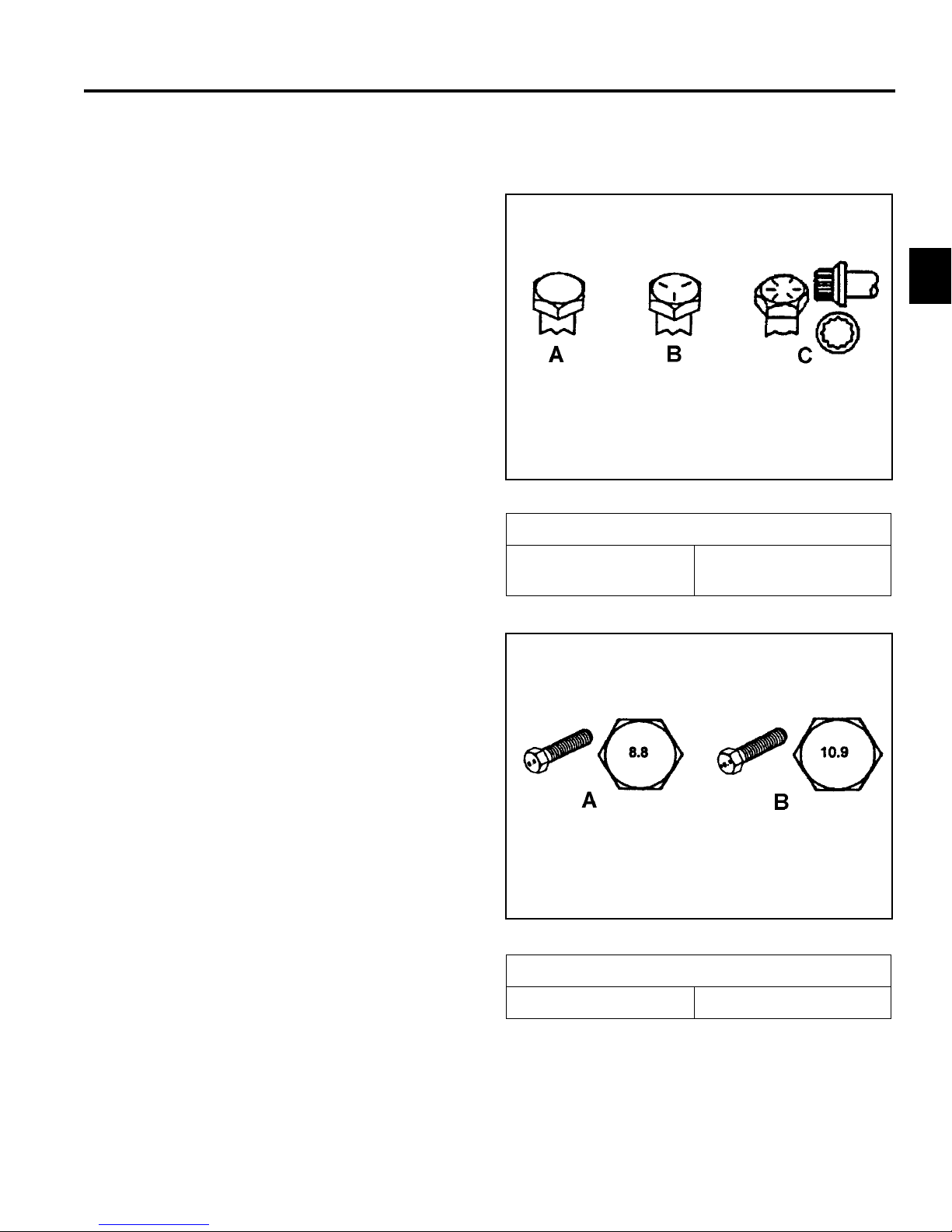
Fastener Identification
Inch Series Bolts and Screws
(A) Grade 1
(B) Grade 5
2
Figure 1
(C) Grade 8
The standard method of verifying torque shall be
performed by marking a line on the fastener (head or
nut) and mating part, then back off fastener 1/4 of a
turn. Measure the torque required to tighten the
fastener until the lines match up.
Figure 2
Metric Bolts and Screws
(A) Class 8.8 (B) Class 10.9
2-1LX Lawn Tractor Service Manual
Page 10

SPECIFICATIONS
Standard Torque for Dry, Zinc Plated, and Steel Fasteners (Inch Series)
2
Grade 1, 5, &
Thread Size
# 6 - 32 UNC
# 6 - 40 UNF 17 ± 2 190 ± 20 25 ± 2 280 ± 20
# 8 - 32 UNC
# 8 - 36 UNF 31 ± 3 350 ± 30 43 ± 4 31 ± 3
# 10 - 24 UNC
#10 - 32 UNF 48 ± 4 540 ± 45 68 ± 6 765 ± 70
1/4 - 20 UNC 48 ± 7 53 ± 7 599 ± 79 100 ± 10 1125 ± 100 140 ± 15 1580 ± 170
1/4 - 28 UNF 53 ± 7 65 ± 10 734 ± 113 115 ± 10 1300 ± 100 160 ± 15 1800 ± 170
5/16 - 18 UNC 115 ± 15 105 ± 17 1186 ± 169 200 ± 25 2250 ± 280 300 ± 30 3390 ± 340
5/16 - 24 UNF 138 ± 17 128 ± 17 1446 ± 192 225 ± 25 2540 ± 280 325 ± 30 3670 ± 340
3/8 - 16 UNC 16 ± 2 16 ± 2 22 ± 3 30 ± 3 41 ± 4 43 ± 4 58 ± 5
3/8 - 24 UNF 17 ± 2 18 ± 2 24 ± 3 35 ± 3 47 ± 4 50 ± 4 68 ± 5
7/16 - 14 UNC 27 ± 3 27 ± 3 37 ± 4 50 ± 5 68 ± 7 70 ± 7 68 ± 9
7/16 - 20 UNF 29 ± 3 29 ± 3 39 ± 4 55 ± 5 75 ± 7 77 ± 7 104 ± 9
1/2 - 13 UNC 30 ± 3 48 ± 7 65 ± 9 75 ± 8 102 ± 11 105 ± 10 142 ± 14
1/2 - 20 UNF 32 ± 3 53 ± 7 72 ± 9 85 ± 8 115 ± 11 120 ± 10 163 ± 14
5/8 - 11 UNC 65 ± 10 88 ± 12 119 ± 16 150 ± 15 203 ± 20 210 ± 20 285 ± 27
5/8 - 18 UNF 75 ± 10 95 ± 15 129 ± 20 170 ± 15 230 ± 20 240 ± 20 325 ± 27
3/4 - 10 UNC 93 ± 12 140 ± 20 190 ± 27 265 ± 25 359 ± 34 374 ± 35 508 ± 47
3/4 - 16 UNF 115 ± 15 165 ± 25 224 ± 34 300 ± 25 407 ± 34 420 ± 35 569 ± 47
7/8 - 9 UNC 140 ± 20 225 ± 25 305 ± 34 430 ± 45 583 ± 61 600 ± 60 813 ± 81
7/8 - 14 UNF 155 ± 25 260 ± 30 353 ± 41 475 ± 45 644 ± 61 660 ± 60 895 ± 81
8 with Thin
Height Nuts
In-lb In-lb N-cm In-lb N-cm In-lb N-cm
10 ± 2 13 ± 2 147 ± 23
13 ± 2 25 ± 5 282 ± 30
18 ± 2 30 ± 5 339 ± 56
ft-lb ft-lb N-m ft-lb N-m ft-lb N-m
SAE Grade 1 Bolts, Screws,
Studs, & Sems with Regular
Height Nuts (SAE J995 Grade
2 or Stronger Nuts)
SAE Grade 5 Bolts, Screws,
Studs, & Sems with Regular
Height Nuts (SAE J995 Grade
2 or Stronger Nuts)
15 ± 2 170 ± 20 23 ± 2 260 ± 20
29 ± 3 330 ± 30 41 ± 4 460 ± 45
42 ± 4 475 ± 45 60 ± 6 674 ± 70
SAE Grade 8 Bolts, Screws,
Studs, & Sems with Regular
Height Nuts (SAE J995 Grade
2 or Stronger Nuts)
Note: Reduce torque values listed in the table above
by 25% for lubricated fasteners. Lubricated fasteners
are defined as threads coated with a lubricant such as
oil, graphite, or thread sealant such as Loctite.
Note: Torque values may have to be reduced when
installing fasteners into threaded aluminum or brass.
The specific torque value should be determined based
on the fastener size, the aluminum or base material
strength, length of thread engagement, etc.
2-2 LX Lawn Tractor Service Manual
Note: The nominal torque values listed above for
Grade 5 and 8 fasteners are based on 75% of the
minimum proof load specified in SAE J429. The
tolerance is approximately
value. Thin height nuts include jam nuts.
± 10% of the nominal torque
Page 11

SPECIFICATIONS
Standard Torque for Dry, Zinc, and Steel Fasteners (Metric Fasteners)
Class 8.8 Bolts, Screws, and Studs with
Thread Size
M5 X 0.8 57 ± 5 in-lb 640 ± 60 N-cm 78 ± 7 in-lb 885 ± 80 N-cm
M6 X 1.0 96 ± 9 in-lb 1018 ± 100 N-cm 133 ± 13 in-lb 1500 ± 150 N-cm
M8 X 1.25 19 ± 2 ft-lb 26 ± 3 N-m 27 ± 2 ft-lb 36 ± 3 N-m
M10 X 1.5 38 ± 4 ft-lb 52 ± 5 N-m 53 ± 5 ft-lb 72 ± 7 N-m
M12 X 1.75 66 ± 7 ft-lb 90 ± 10 N-m 92 ± 9 ft-lb 125 ± 12 N-m
M16 X 2.0 166 ± 15 ft-lb 225 ± 20 N-m 229 ± 22 ft-lb 310 ± 30 N-m
M20 X 2.5 325 ± 33 ft-lb 440 ± 45 N-m 450 ± 37 ft-lb 610 ± 50 N-m
Note: Reduce torque values listed in the table above
by 25% for lubricated fasteners. Lubricated fasteners
are defined as threads coated with a lubricant such as
oil, graphite, or thread sealant such as Loctite.
Note: Torque values may have to be reduced when
installing fasteners into threaded aluminum or brass.
The specific torque value should be determined based
on the fastener size, the aluminum or base material
strength, length of thread engagement, etc.
Regular Height Nuts
(Class 8 or Strong Nuts)
Note: The nominal torque values listed above are
based on 75% of the minimum proof load specified in
SAE J1199. The tolerance is approximately
the nominal torque value. Thin height nuts include jam nuts.
Class 10.9 Bolts, Screws, and Studs with
Regular Height Nuts (
Class 10 or Strong Nuts)
2
± 10% of
2-3LX Lawn Tractor Service Manual
Page 12

SPECIFICATIONS
Other Torque Specifications
2
SAE Grade 8 Steel Set Screws
Recommended Torque
Thread Size
Square Head Hex Socket
1/4 - 20 UNC 140 ± 20 in-lb 73 ± 12 in-lb
5/16 - 18 UNC 215 ± 35 in-lb 145 ± 20 in-lb
3/8 - 16 UNC 35 ± 10 ft-lb 18 ± 3 ft-lb
1/2 - 13 UNC 75 ± 15 ft-lb 50 ± 10 ft-lb
Thread Cutting Screws
(Zinc Plated Steel)
Type 1, Type 23, or Type F
Thread Size Baseline Torque*
No. 6 - 32 UNC 20 ± 5 in-lb
Wheel Bolts and Lug Nuts
Thread Size Recommended Torque**
7/16 - 20 UNF
Grade 5
1/2 - 20 UNF
Grade 5
M12 X 1.25
Class 8.8
M12 X 1.5
Class 8.8
** For steel wheels and non-lubricated fasteners.
Thread
Size
No. 6 18 20 20 ± 5 in-lb
Threads per Inch
Type A Type B
65 ± 10 ft-lb 88 ± 14 N-m
80 ± 10 ft-lb 108 ± 14 N-m
80 ± 10 ft-lb 108 ± 14 N-m
80 ± 10 ft-lb 108 ± 14 N-m
Thread Cutting Screws
(Zinc Plated Steel)
Baseline Torque*
No. 8 - 32 UNC 30 ± 5 in-lb
No.10 - 24 UNC 38 ± 7 in-lb
1/4 - 20 UNC 85 ± 15 in-lb
5/16 - 18 UNC 110 ± 20 in-lb
3/8 - 16 UNC 200 ± 100 in-lb
Conversion Factors
in-lb X 11.2985 - N-cm
ft-lb X 1.3558 = N-m
No. 8 15 18 30 ± 5 in-lb
No. 10 12 16 38 ± 7 in-lb
No. 12 11 14 85 ± 15 in-lb
* Hole size, material strength, material thickness and
finish must be considered when determining specific
torque values. All torque values are based on nonlubricated fasteners.
N-cm X - 0.08851 = in-lb
N-cm X 0.73776 - ft-lb
2-4 LX Lawn Tractor Service Manual
Page 13
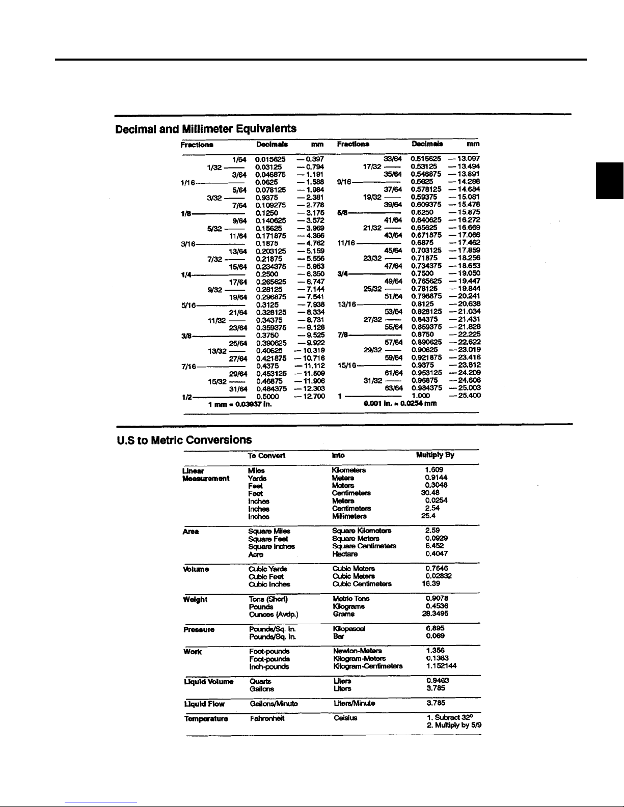
Equivalents and Conversions
SPECIFICATIONS
2
2-5LX Lawn Tractor Service Manual
Page 14

2
SPECIFICATIONS
Product Specifi cations
Name LX420 LX425 LX460 LX465 LX500
Engine 18 HP
Single Cylinder
Kohler Courage
RPM Setting -
High
RPM Setting –
Low
Construction
Fuel Capacity
Wheel Base 46” (116.8cm) 46” (116.8cm) 46” (116.8cm) 46” (116.8cm) 46” (116.8cm)
Overall Length 68” (172.7cm) 68” (172.7cm) 68” (172.7cm) 68” (172.7cm) 68” (172.7cm)
Overall Width 42” (114.3cm) 42” (114.3cm) 48” (127.9cm) 49” (124.4cm) 54” (137.2cm)
Overall Height 43” (109.2cm) 43” (109.2cm) 43” (109.2cm) 43” (109.2cm) 43” (109.2cm)
Weight
(approximate)
Traction System CVT* Transaxle CVT* Transaxle CVT* Transaxle Hydro-Gear
Ground Speed –
Forward
Ground Speed –
Reverse
Front Tires
Rear Tires 20 x 8 20 x 8 20 x 8 20 x 8 20 x 10
Tire Pressure
(Front/Rear)
Turning Radius
Electrical
System
3450 + 75 3450 + 75 3450 + 75 3450 + 75 3300 + 75
1700 + 150 1700 + 150 1700 + 150 1700 + 150 1750 + 150
498 lbs.
(225.9kg)
0 – 5.5 mph 0 – 5.5 mph 0 – 5.5 mph 0 – 6.4 mph 0 – 5.5 mph
0 – 2.3 mph 0 – 2.3 mph 0 – 2.3 mph 0 – 2.5 mph 0 – 2.3 mph
20 HP
Single Cylinder
Kohler Courage
498 lbs.
(225.9kg)
Alternator: 15 Amp Regulated
20 HP
Single Cylinder
Kohler Courage
12 Gauge Steel Frame
3.0 Gallon (11.4 Liters)
501 lbs.
(227.25kg)
15 x 6
14psi / 10psi
18” (46cm)
Voltage: 12-volt Negative
Ground Battery: 190 CCA
Fuse: 20 Amp
20 HP
Single Cylinder
Kohler Courage
498 lbs.
(225.9kg)
LT-0510
22 HP
Twin Cylinder
Kohler Courage
525 lbs.
(238kg)
CVT* Transaxle
42”, Two Blade,
Mower Deck
CVT = Constant Velocity Transaxle
2-6 LX Lawn Tractor Service Manual
13 Gauge Steel
42”, Two Blade,
13 Gauge Steel
46”, Three Blade,
12 Gauge Steel
46”, Three Blade,
12 Gauge Steel
50”, Three Blade,
12 Gauge Steel
Page 15
CHASSIS
Front Pivot Axle Replacement
Removal
1. Disconnect the negative and then the positive
battery cable.
2. Remove the mower deck: 42” deck on page 7-64;
46” deck on page 7-69; 50” deck on page 7-74.
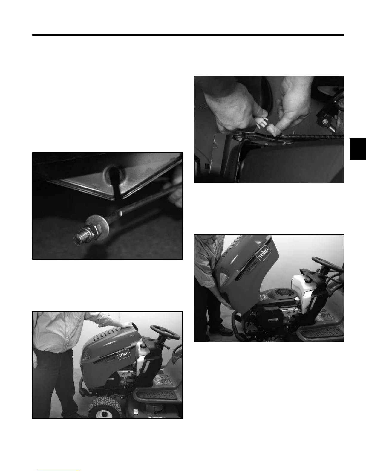
3. Remove the deck rod from the deck hanger bracket
(Fig. 001).
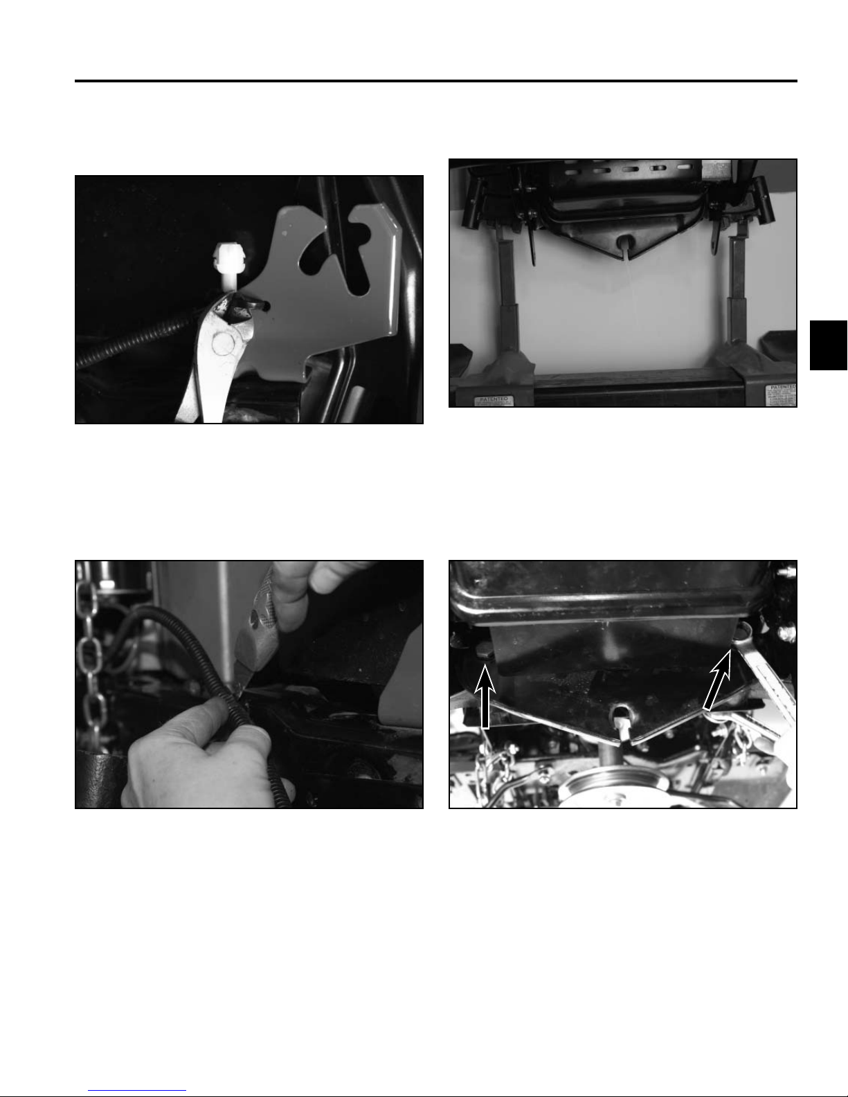
5. Unplug the headlights from the wire harness (Fig.
003).
3
Fig 003 PICT-7064
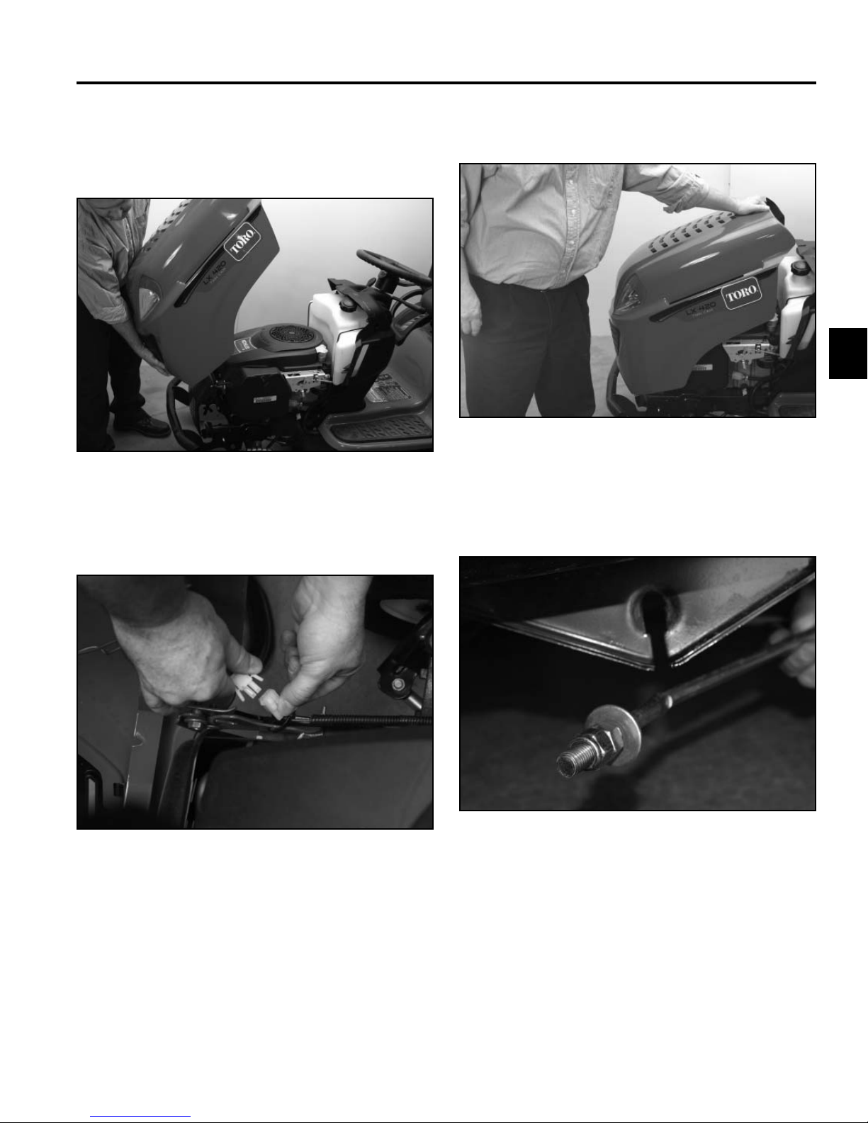
6. Remove the hood from the frame (Fig. 004).
Fig 001 PICT-7399a
4. Raise the hood (Fig. 002).
Fig 002 PICT-7063
Fig 004 PICT-7066
3-1LX Lawn Tractor Service Manual
Page 16
3
CHASSIS
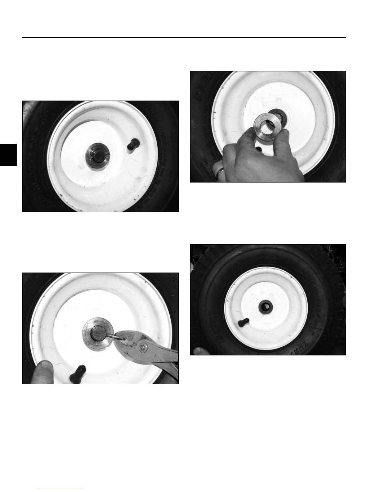
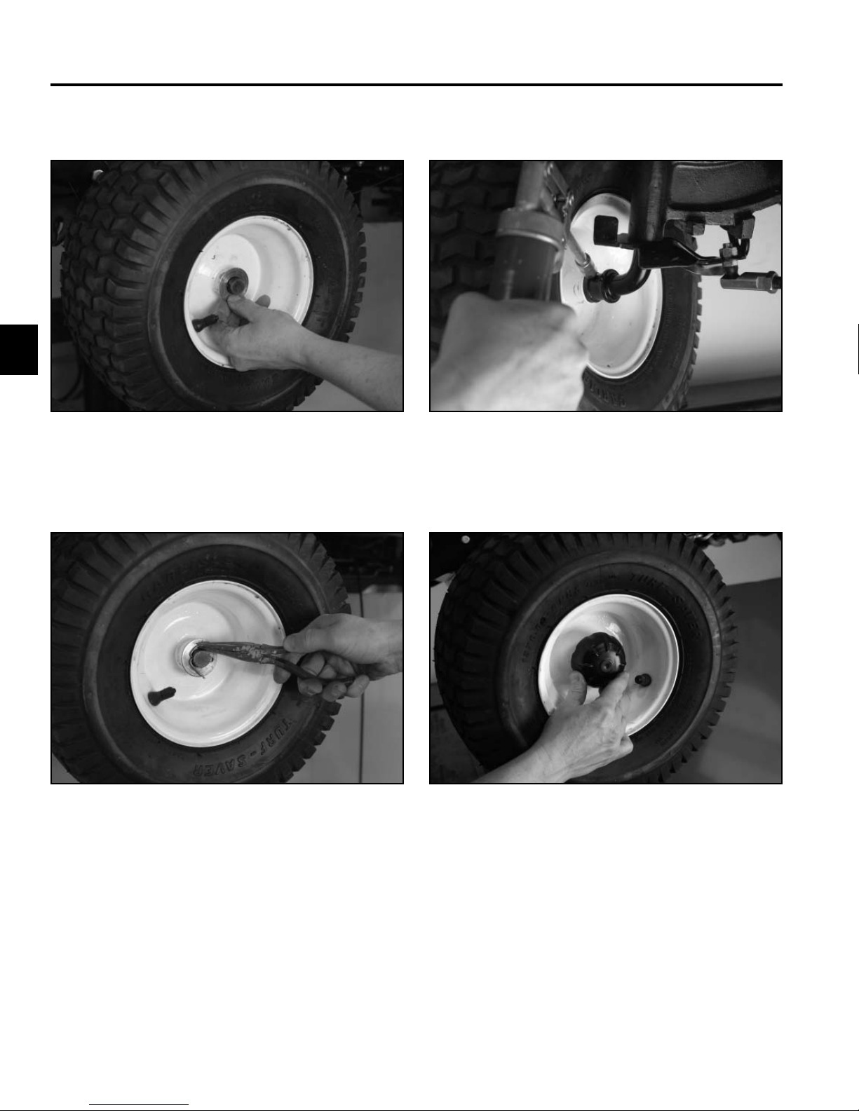
10. Remove the washer from the two axles (Fig. 007).7. Elevate and secure the front end of the machine so
the front axle can be accessed.
8. Remove the hub caps from the two front tires (Fig.
005).
Fig 007 PICT-7402
Fig 005 PICT-7400
9. Remove and discard the cotter pins from the two
axles (Fig. 006).
Fig 006 PICT-7401
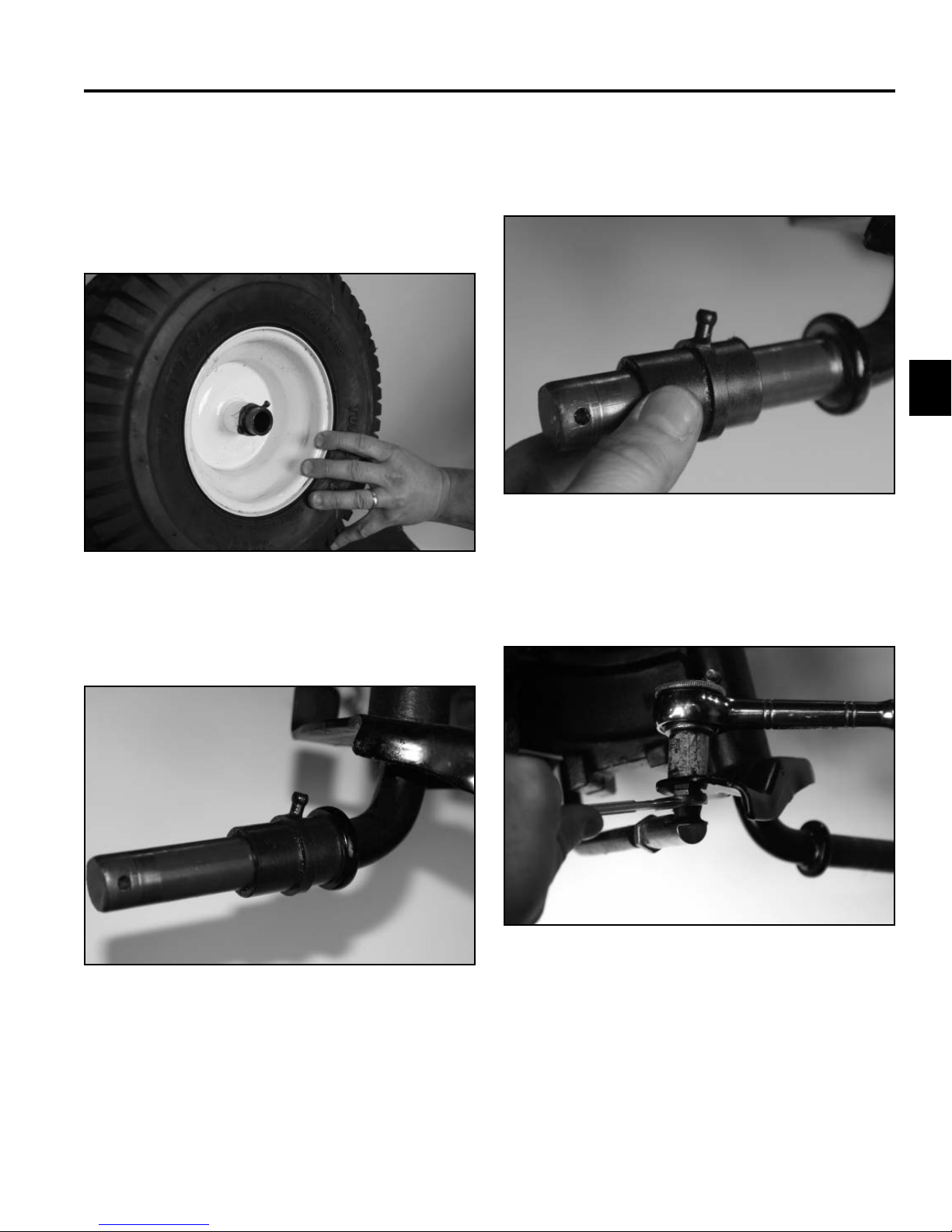
11. Remove the wheel and tire assembly from the two
axle assemblies (Fig. 008).
Fig 008 PICT-7403
3-2 LX Lawn Tractor Service Manual
Page 17
CHASSIS
Note: There are inner and outer bushings included
with the rim assembly. When the wheel is
removed, the inner bushing may come off
with the wheel or stay on the axle.
Bushing stays in rim of tire (Fig. 009):
Fig 009 PICT-7410a
12. Remove the bushing from each of the axle assem-
blies if it stayed in place at tire assembly removal
(Fig. 011).
3
Fig 011 PICT-7415a
13. Remove the nut securing the ball joint to the axle
assemblies (Fig. 012).
Bushing stays on axle (Fig. 010):
Fig 010 PICT-7413
Fig 012 PICT-7421
3-3LX Lawn Tractor Service Manual
Page 18
CHASSIS
3
14. Remove the ball joint from the axle assembly (Fig.
013).
Fig 013 PICT-7423
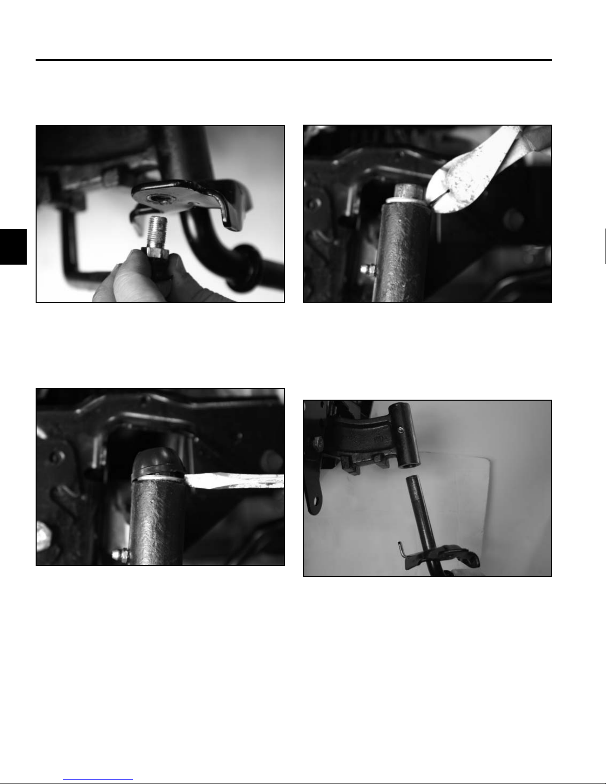
15. Remove the cap from the axle assembly (Fig. 014). 17. Remove the axle assembly from the front pivot axle
16. Remove the push nut from the axle assembly (Fig.
015).
Fig 015 PICT-7425
(Fig. 016).
Fig 014 PICT-7424
3-4 LX Lawn Tractor Service Manual
Fig 016 PICT-7431a
18. Repeat steps 13-17 to remove the second axle.
Page 19
right hand hood pivot bracket (Fig. 017).
Fig 017 PICT-7434
CHASSIS
21. Support the front pivot axle (Fig. 019).19. Cut the cable tie securing the wire harness to the
3
Fig 019 PICT-7439a
20. Cut the electrical tape securing the wire harness to
the plastic harness guide (Fig. 018).
Fig 018 PICT-7462a
22. Remove the nuts from the 2 bolts securing the pivot
axle and deck hanger bracket to the frame (Fig.
020).
Fig 020 PICT-7442
3-5LX Lawn Tractor Service Manual
Page 20
CHASSIS
3
23. Remove the 4 bolts (2 on the right, 2 on the left)
securing the left and right pivot supports to the frame
(Fig. 021).
Fig 021 PICT-7436
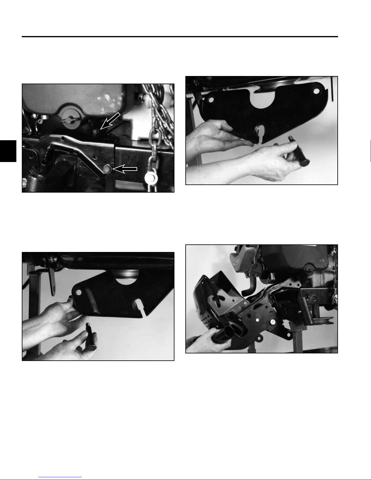
24. Remove one of the bolts securing the deck hanger
plate and pivot axle to the frame (Fig. 022).
25. Remove the second bolt and deck hanger plate from
the pivot axle (Fig. 023).
Fig 023 PICT-7447
26. Remove the muffl er, heat shield and bracket assem-
bly (Fig. 024).
Fig 022 PICT-7444
3-6 LX Lawn Tractor Service Manual
Fig 024 PICT-7449
Page 21
CHASSIS
27. Remove the pivot bar bracket (Fig. 025).
Fig 025 PICT-7450
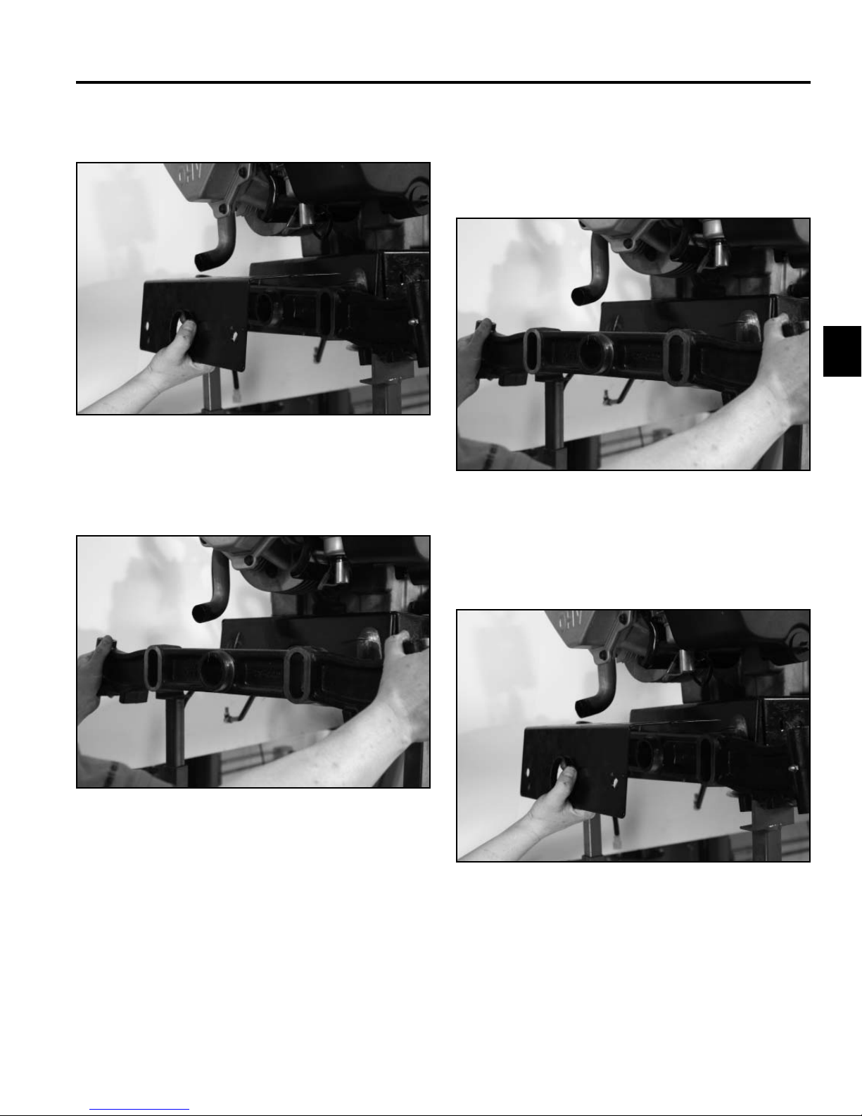
28. Remove the front pivot axle (Fig. 026).
Installation
1. Position the front pivot axle to the front of the frame
(Fig. 027).
3
Fig 027 PICT-7451
Fig 026 PICT-7451
2. Position the pivot bar bracket to the front pivot axle
(Fig. 028).
Fig 028 PICT-7450
3-7LX Lawn Tractor Service Manual
Page 22

CHASSIS
3
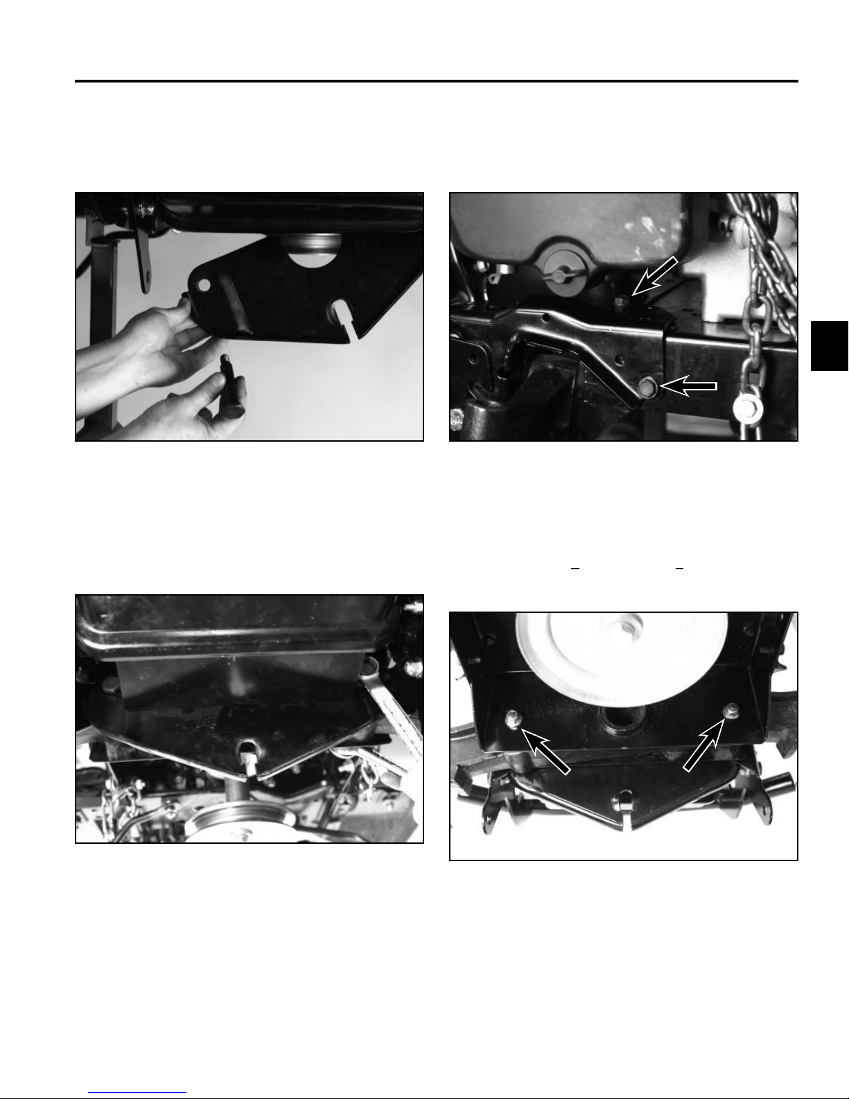
3. Position the muffl er, heat shield and bracket assem-
bly to the frame (Fig. 029).
Fig 029 PICT-7449
Note: The tailpipe needs to be aligned and inserted
into the muffl er upon assembly (Fig. 030).
4. Loosely install 4 bolts securing the left and right pivot
supports to the frame (2 bolts on the left side bracket
and 2 bolts on the right side bracket) (Fig. 031).
Fig 031 PICT-7436
5. Position the deck hanger plate to the pivot axle and
install a shoulder bolt (Fig. 032).
Fig 030 PICT-7457
3-8 LX Lawn Tractor Service Manual
Fig 032 PICT-7447
Page 23
CHASSIS
6. Align the second hole in the deck hanger bracket
with the pivot axle and install a second shoulder bolt
(Fig. 033).
Fig 033 PICT-7444
8. Tighten the 4 bolts securing the left and right pivot
supports to the frame (2 bolts on the left side bracket
and 2 bolts on the right side bracket) (Fig. 035).
3
Fig 035 PICT-7436
7. Loosely install a nut onto the 2 shoulder bolts securing the pivot axle and deck hanger bracket to the
frame (Fig. 034).
Fig 034 PICT-7442
9. Torque the 2 nuts installed on the shoulder bolts
securing the pivot axle and deck hanger bracket to
the frame to 30 + 3 ft-lbs. (40.67 + 4.06 Nm) (Fig.
036).
Fig 036 PICT-7460
3-9LX Lawn Tractor Service Manual
Page 24
CHASSIS
3
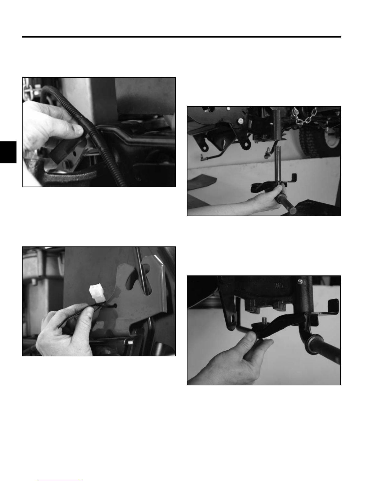
10. Apply electrical tape to secure the wire harness to
the plastic harness guide (Fig. 037).
Fig 037 PICT-7464
11. Secure the wire harness to the right hand hood pivot
bracket with a cable tie (Fig. 038).
Note: The following steps, 12 thru 21, should be
done on both the right and left sides of the
axle.
12. Insert the axle assembly into the pivot axle (Fig.
039).
Fig 039 PICT-7468a
Fig 038 PICT-7466
13. Position the ball joint into the axle assembly (Fig.
040).
Fig 040 PICT-7469a
3-10 LX Lawn Tractor Service Manual
Page 25
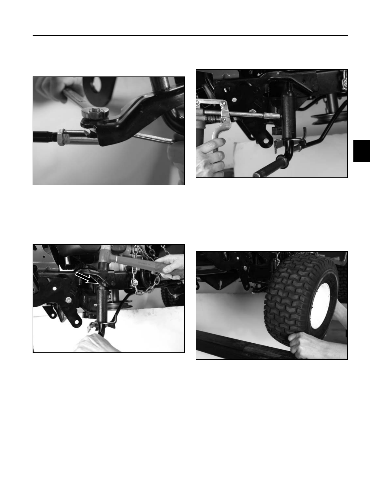
29 ft-lbs. (16.94 to 39.54 Nm) (Fig. 041).
Fig 041 PICT-7470a
CHASSIS
16. Apply grease to the axle assembly (Fig. 043).14. Install a nut onto the ball joint and torque to 12.5 to
3
Fig 043 PICT-7472
15. Install a cap/push nut onto the axle assembly (Fig.
042).
Fig 042 PICT-7471
17. Slide the wheel and tire assembly onto the axle
assembly (Fig. 044).
Note: The wheel bearing is installed in the rim.
Fig 044 PICT-7473
3-11LX Lawn Tractor Service Manual
Page 26
3
CHASSIS
20. Apply grease to the wheel bearing (Fig. 047).18. Install a washer onto the axle assembly (Fig. 045).
Fig 045 PICT-7474a
19. Install a cotter pin into the axle assembly (Fig. 046). 21. Install the hub cap (Fig. 048).
Fig 046 PICT-7475a
Fig 047 PICT-7477a
Fig 048 PICT-7478
3-12 LX Lawn Tractor Service Manual
Page 27
23. Position the hood on the chassis (Fig. 049).
Fig 049 PICT-7066
CHASSIS
25. Lower the hood (Fig. 051).22. Lower the machine.
3
Fig 051 PICT-7063
24. Plug the headlights into the wire harness (Fig. 050).
Fig 050 PICT-7064
26. Install the deck rod into the deck hanger bracket
(Fig. 052).
Fig 052 PICT-7399a
27. Install the mower deck: 42” deck on page 7-67; 46”
deck on page 7-72; 50” deck on page 7-76.
28. Connect the positive and then the negative battery
cable.
29. Check the toe-in measurement and adjust as needed. Refer to “Front Wheel Toe-In Measurement” on
page 3-85.
3-13LX Lawn Tractor Service Manual
Page 28
CHASSIS
3
Axle Assembly Replacement
Removal
1. Raise the front of the machine.
2. Remove the hub cap (Fig. 053).
Fig 053 PICT-7067
4. Remove the washer from the axle assembly (Fig.
055).
Fig 055 PICT-7070
5. Remove the wheel and tire assembly from the axle
assembly (Fig. 056).
3. Remove the cotter pin from the axle assembly (Fig.
054).
Fig 054 PICT-7069
Fig 056 PICT-7072
3-14 LX Lawn Tractor Service Manual
Page 29
CHASSIS
Note: There are inner and outer bushings included
with the rim assembly. When the wheel is
removed, the inner bushing may come off
with the wheel or stay on the axle assembly.
Bushing stays in rim of tire (Fig. 057):
Fig 057 PICT-7410a
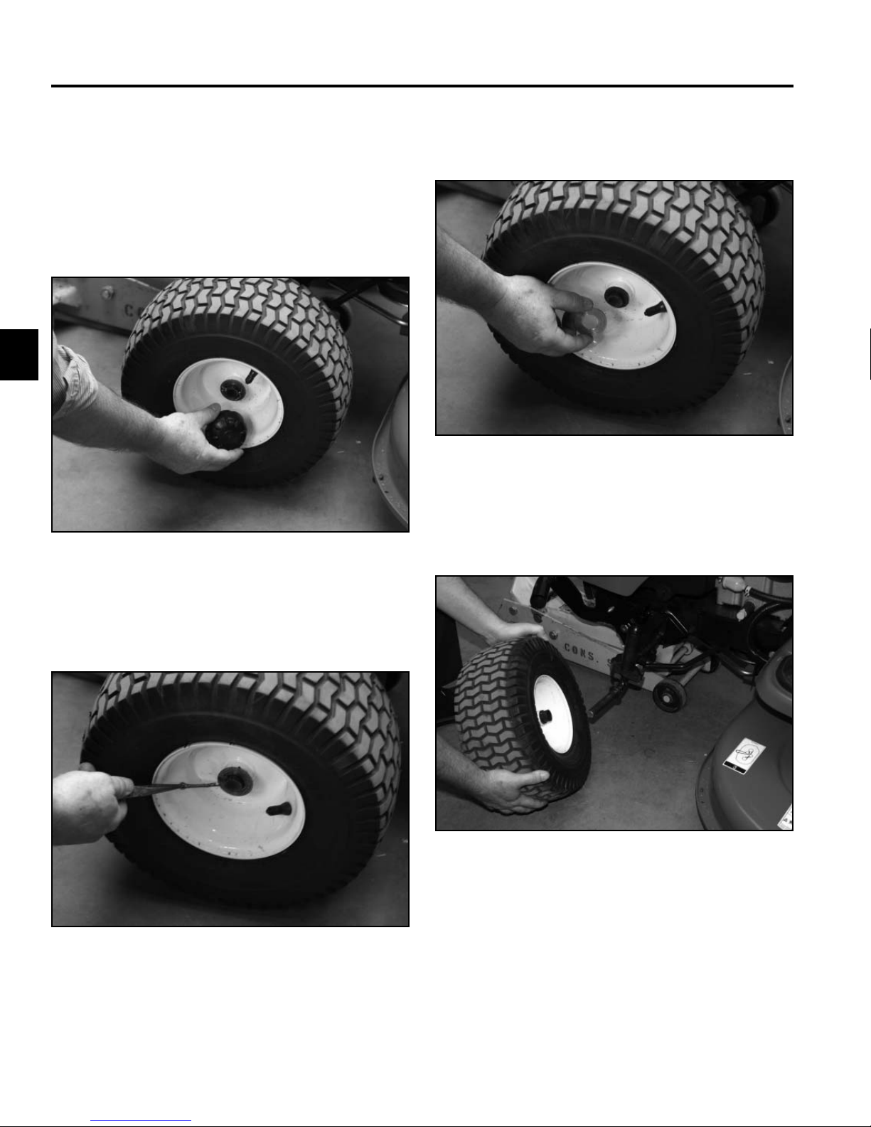
6. Remove the bushing from each of the axle assem-
blies if it stayed in place at tire assembly removal
(Fig. 059).
3
Fig 059 PICT-7415a
7. Remove the nut securing the ball joint to the axle
assembly (Fig. 060).
Bushing stays on axle assembly (Fig. 058):
Fig 058 PICT-7413
Fig 060 PICT-7077a
3-15LX Lawn Tractor Service Manual
Page 30
CHASSIS
3
8. Remove the ball joint from the axle assembly (Fig.
061).
Fig 061 PICT-7078
9. Remove the cap from the axle assembly (Fig. 062).
10. Remove the push nut from the axle assembly (Fig.
063).
Fig 063 PICT-7425
11. Remove the axle assembly from the axle pivot (Fig.
064).
Fig 062 PICT-7424
3-16 LX Lawn Tractor Service Manual
Fig 064 PICT-7087
Page 31

CHASSIS
Installation
1. Position the axle assembly into the axle pivot (Fig.
065).
Fig 065 PICT-7087
2. Install a cap/push nut onto the axle assembly (Fig.
066).
3. Position the ball joint into the axle assembly (Fig.
067).
4. Install a nut onto the ball joint and torque to 12.5 to
29 ft-lbs. (16.94 to 39.54 Nm) (Fig. 068).
Fig 067 PICT-7078
3
Fig 066 PICT-7471
Fig 068 PICT-7077a
3-17LX Lawn Tractor Service Manual
Page 32

CHASSIS
3
5. Apply grease to lubricate the front axle pivot (Fig.
069).
Fig 069 PICT-7091a
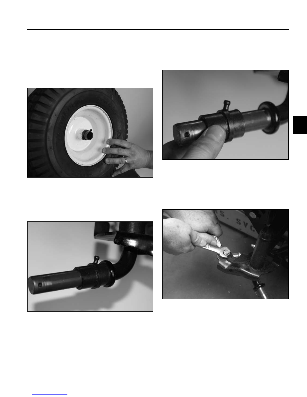
6. Slide the wheel and tire assembly onto the axle
assembly (Fig. 070).
7. Install a washer onto the axle assembly (Fig. 071).
Fig 071 PICT-7070
8. Install a cotter pin into the axle pivot (Fig. 072).
Note: The wheel bearing is installed in the rim.
Fig 070 PICT-7072
Fig 072 PICT-7093
3-18 LX Lawn Tractor Service Manual
Page 33

CHASSIS
9. Apply grease to the wheel bearing (Fig. 073).
Fig 073 PICT-7092
10. Install the hub cap (Fig. 074).
Steering Wheel Replacement
Removal
1. Remove the steering wheel cap (Fig. 075).
3
Fig 075 PICT-7103
Fig 074 PICT-7067
11. Lower the machine.
2. Remove the bolt and washer securing the steering
wheel to the steering shaft (Fig. 076).
Fig 076 PICT-7104
3-19LX Lawn Tractor Service Manual
Page 34

CHASSIS
3
3. Remove the steering wheel (Fig. 077).
Fig 077 PICT-7105
Installation
1. Position the front tires so that they are pointing
straight forward. Slide the steering wheel onto the
steering shaft (Fig. 078).
2. Install the washer and bolt to secure the steering
wheel to the steering shaft (Fig. 079).
3. Install the steering wheel cap (Fig. 080).
Fig 079 PICT-7104
Fig 078 PICT-7105
3-20 LX Lawn Tractor Service Manual
Fig 080 PICT-7106
Page 35

CHASSIS
Steering Shaft Replacement
Removal
1. Remove the steering wheel cap (Fig. 081).
Fig 081 PICT-7103
3. Remove the steering wheel (Fig. 083).
3
Fig 083 PICT-7105
4. Raise the hood (Fig. 084).
2. Remove the bolt and washer securing the steering
wheel to the steering shaft (Fig. 082).
Fig 082 PICT-7104
Fig 084 PICT-7063a
3-21LX Lawn Tractor Service Manual
Page 36

3
CHASSIS
8. Lift the fuel tank out of the tower (Fig. 087).5. Remove the mower deck: 42” deck on page 7-64;
46” deck on page 7-69; 50” deck on page 7-74.
6. Disconnect the fuel line from the fuel fi lter and drain
all the fuel from the fuel tank. Reconnect the fuel line
to the fuel fi lter (Fig. 085).
Fig 087 PICT-7655a
Fig 085 PICT-7094
7. Remove the two screws securing the fuel tank
support rods to the dash supports (Fig. 086).
Fig 086 PICT-7099a
9. Raise the machine to access the steering gear
assembly.
10. Secure the steering gear in place with a Phillips
screwdriver and remove the nut from the end of the
steering shaft (Fig. 088).
Fig 088 PICT-7656a
3-22 LX Lawn Tractor Service Manual
Page 37

11. Remove the pinion from the steering shaft (Fig. 089). 13. Lower the machine.
14. Pull the steering shaft up out of the hex fl ange bear-
ing, angle the steering shaft in between the pedal
levers and lower it out of the tower (Fig. 091).
Fig 089 PICT-7659a
CHASSIS
3
12. Push up on the steering shaft and remove the
washer (Fig. 090).
Fig 090 PICT-7661a
Fig 091 PICT-7663
15. Remove the hex fl ange bushing (Fig. 092).
Note: Inspect the hex fl ange bushing and replace if
worn or damaged.
Fig 092 PICT-7666a
3-23LX Lawn Tractor Service Manual
Page 38

CHASSIS
3
Installation
1. Install the hex fl ange bushing into the steering
support bracket ensuring the hex is seated in the
bracket (Fig. 093).
Fig 093 PICT-7668a
3. Raise the tractor.
4. Push up on the steering shaft to install a washer
onto the steering shaft (Fig. 095).
Fig 095 PICT-7661a
2. Slide the steering shaft up into the tower from below,
insert the lower end of the steering shaft into the hex
fl ange bushing (Fig. 094).
Fig 094 PICT-7663
5. Slide the pinion onto the steering shaft (Fig. 096).
Fig 096 PICT-7659a
3-24 LX Lawn Tractor Service Manual
Page 39

CHASSIS
6. Loosely install a nut on the steering shaft. Secure
the steering gear in place with a Phillips screwdriver
and tighten the nut (Fig. 097).
Fig 097 PICT-7656a
7. Grease the pinion gear with #2 general purpose
grease (Fig. 098).
8. Lower the tractor.
9. Position the fuel tank into the tower (Fig. 099).
3
Fig 099 PICT-7655a
10. Position the fuel tank support rods and install two
screws securing the fuel tank support rods to the
dash supports (Fig. 100).
Fig 098 PICT-7676
Fig 100 PICT-7099a
3-25LX Lawn Tractor Service Manual
Page 40

3
CHASSIS
11. Lower the hood (Fig. 101). 13. Install the washer and bolt to secure the steering
wheel to the steering shaft (Fig. 103).
Fig 101 PICT-7063a
Fig 103 PICT-7104
12. With the tractor’s wheels straight ahead, position the
steering wheel onto the steering shaft (Fig. 102).
Fig 102 PICT-7105
14. Install the steering wheel cap (Fig. 104).
Fig 104 PICT-7106
15. Install the mower deck: 42” deck on page 7-67; 46”
deck on page 7-72; 50” deck on page 7-76.
3-26 LX Lawn Tractor Service Manual
Page 41

CHASSIS
Electric PTO Clutch Replacement
Removal
1. Remove the mower deck from the tractor. Refer to
“50” Mower Deck Removal” on page 7-74.
2. Raise the tractor so the clutch can be accessed.
3. Unplug the clutch from the wire harness (Fig. 105).
4. Route the clutch connector out through the slot in
the frame.
5. Remove the bolt and lock washer securing the clutch
to the crankshaft (Fig. 106).
3
Fig 106 PICT-7982
Fig 105 PICT-7977a
6. Remove the clutch and washer(s) from the crankshaft (Fig. 107).
Fig 107 PICT-7988
3-27LX Lawn Tractor Service Manual
Page 42

CHASSIS
3
Installation
1. Apply anti-seize compound to the crankshaft (Fig.
108).
Fig 108 PICT-7984
3. Align the keyway in the clutch with the key on the
crankshaft and slide the clutch and washer assembly
onto the crankshaft. (Fig. 110).
Fig 110 PICT-7988
2. Lay the washer(s) on top of the clutch (Fig. 109).
Fig 109 PICT-7985
4. Install the bolt and lock washer securing the clutch
to the crankshaft. Torque the bolt to 37.5–50 ft-lbs.
(50.84–67.79 Nm) (Fig. 111).
Fig 111 PICT-7986
3-28 LX Lawn Tractor Service Manual
Page 43

CHASSIS
5. Route the clutch plug through the slot in the frame.
6. Plug the clutch into the wire harness (Fig. 112).
Fig 112 PICT-7977a
7. Lower the tractor to the ground.
Fuel Tank Replacement
Removal
1. Raise the hood (Fig. 113).
3
Fig 113 PICT-7063
8. Install the mower deck onto the tractor. Refer to “50”
Mower Deck Installation” on page 7-76.
2. Disconnect the fuel line from the fuel fi lter and drain
all the fuel from the fuel tank into an approved
container (Fig. 114).
Fig 114 PICT-7094
3-29LX Lawn Tractor Service Manual
Page 44

CHASSIS
3
3. Remove the two screws securing the fuel tank
support rods to the dash supports (Fig. 115).
Fig 115 PICT-7099a
4. Remove the fuel tank from the engine compartment
(Fig. 116).
Installation
1. Position the fuel tank into the engine compartment
(Fig. 117).
Fig 117 PICT-7100a
2. Position the fuel tank support rods and install screws
to secure the fuel tank (Fig. 118).
Fig 116 PICT-7100a
3-30 LX Lawn Tractor Service Manual
Fig 118 PICT-7099a
Page 45

CHASSIS
3. Connect the fuel line to the fuel fi lter and secure with
a hose clamp (Fig. 119).
Fig 119 PICT-7094
4. Lower the hood (Fig. 120).
Hood Replacement
Removal
1. Raise the hood (Fig. 121).
3
Fig 121 PICT-7063
Fig 120 PICT-7063
2. Unplug the headlights from the wire harness (Fig.
122).
Fig 122 PICT-7064
3-31LX Lawn Tractor Service Manual
Page 46

3
CHASSIS
2. Plug the headlights to the wire harness (Fig. 125).3. Remove the hood from the chassis (Fig. 123).
Fig 123 PICT-7066
Installation
1. Position the hood on the chassis (Fig. 124).
Fig 125 PICT-7064
3. Lower the hood (Fig. 126).
Fig 126 PICT-7063
Fig 124 PICT-7066
3-32 LX Lawn Tractor Service Manual
Page 47

CHASSIS
Fender Replacement
Removal
1. Lift the seat to access the battery compartment.
2. Disconnect the negative battery cable from the
battery terminal (Fig. 127).
4. Remove the battery hold down rod (Fig. 129).
3
Fig 129 PICT-7109a
5. Remove the battery from the battery tray (Fig. 130).
Fig 127 PICT-7107
3. Disconnect the positive battery cable from the
battery terminal (Fig. 128).
Fig 128 PICT-7108
Fig 130 PICT-7110
3-33LX Lawn Tractor Service Manual
Page 48

CHASSIS
3
6. Remove the battery tray (Fig. 131).
Fig 131 PICT-7111
7. Disconnect the two seat switch wires (Fig. 132).
8. Loosen the bolt and nut securing the left seat mount
bracket to the seat bracket (Fig. 133).
Fig 133 PICT-7115
9. Release the extension spring from the seat mount
bracket (Fig. 134).
Fig 132 PICT-7113
3-34 LX Lawn Tractor Service Manual
Fig 134 PICT-7117
Page 49

CHASSIS
10. Remove the 4 bolts securing the seat mount brackets to the fender (Fig. 135).
Fig 135 PICT-7119
11. Remove the seat (Fig. 136).
12. Remove the shifter knob from the shift lever (Fig.
137).
3
Fig 137 PICT-7122
13. Remove the height-of-cut grip from the height-of-cut
lever (Fig. 138).
Fig 136 PICT-7121
Fig 138 PICT-7123
3-35LX Lawn Tractor Service Manual
Page 50

CHASSIS
3
14. Pry up the front portion of the left hand foot pad (Fig.
139).
Fig 139 PICT-7124
15. Remove the bolt, nut and washer securing the fender to the frame (Fig. 140).
16. Pry up the front portion of the right hand foot pad
(Fig. 141).
Fig 141 PICT-7213
17. Remove the bolt nut and washer securing the fender
to the frame (Fig. 142).
Fig 140 PICT-7125
3-36 LX Lawn Tractor Service Manual
Fig 142 PICT-7127a
Page 51

CHASSIS
A
B
18. Locate the 2 screws under the danger decal on the
fender. Cut the decal to expose the bolt heads (Fig.
143).
Fig 143 PICT-7129
19. Remove the 2 screws (Fig. 144).
20. Raise the fender and prop it slightly to access the
fasteners securing the brake pedal to the brake
control assembly (Fig. 145).
3
Fig 145 PICT-7131a
Remove the two sets of fasteners securing the brake
pedal lever to the brake control assembly (Fig. 146):
Fig 144 PICT-7130
A
B
Fig 146 PICT-7132
A. Torx screw and washer
B. Hex head bolt, lock washer and nut
3-37LX Lawn Tractor Service Manual
Page 52

3
CHASSIS
23. Remove the speed control pedal (Fig. 149).21. Remove the brake pedal (Fig. 147).
Fig 147 PICT-7134
22. Remove the two bolts securing the speed control
pedal to the speed control assembly (Fig. 148).
Fig 148 PICT-7135
Fig 149 PICT-7136
24. Remove the fender (Fig. 150).
Fig 150 PICT-7138
3-38 LX Lawn Tractor Service Manual
Page 53

CHASSIS
Installation
1. Position the fender onto the frame (Fig. 151).
Fig 151 PICT-7138
2. Position the speed control pedal to the speed control
assembly (Fig. 152).
3. Install 2 bolts to secure the speed control pedal to
the speed control assembly (Fig. 153).
3
Fig 153 PICT-7211
4. Position the brake pedal to the brake control
assembly (Fig. 154).
Fig 152 PICT-7136
Fig 154 PICT-7212
3-39LX Lawn Tractor Service Manual
Page 54

CHASSIS
A
B
3
5. Raise the fender and prop it slightly to access the
fasteners securing the brake pedal to the brake
control assembly (Fig. 155).
Fig 155 PICT-7131a
7. Begin securing the fender to the frame by installing
2 screws located under the danger decal (Fig. 157).
Glue the cut decal pieces into place or replace the
decal.
Fig 157 PICT-7130
6. Install the two sets of fasteners securing the brake
pedal lever to the brake control assembly (Fig. 156):
A
B
Fig 156 PICT-7132
A. Torx screw and washer
B. Hex head bolt, washer and nut
8. Install the bolt, nut and washer securing the right
side of the fender to the frame and tighten (Fig. 158).
Fig 158 PICT-7127a
3-40 LX Lawn Tractor Service Manual
Page 55

CHASSIS
9. Push the foot pad down to the foot rest by applying
pressure down on the ratchet clip (Fig. 159).
Fig 159 PICT-7216
10. Install the bolt, nut and washer securing the left side
of the fender to the frame and tighten (Fig. 160).
11. Push the left side foot pad down to the foot rest by
applying pressure down on the ratchet clip (Fig.
161).
3
Fig 161 PICT-7217
12. Install the height-of-cut grip onto the height-of-cut
lever (Fig. 162).
Fig 160 PICT-7125
Fig 162 PICT-7123
3-41LX Lawn Tractor Service Manual
Page 56

CHASSIS
3
13. Install the shifter knob onto the shift lever (Fig. 163).
Fig 163 PICT-7122
14. Position the seat onto the fender, aligning the seat
mount bracket holes with the holes in the fender
(Fig. 164).
15. Install the 4 bolts securing the seat mount brackets
to the fender (Fig. 165).
Fig 165 PICT-7119
16. Loosen the bolt and nut securing the left seat mount
bracket to the seat (Fig. 166).
Fig 164 PICT-7121
3-42 LX Lawn Tractor Service Manual
Fig 166 PICT-7115
Page 57

CHASSIS
17. Install the extension spring from the seat mount
bracket to the seat pivot bracket (Fig. 167).
Fig 167 PICT-7117
18. Tighten the bolt and nut to secure the left seat mount
bracket to the seat mount (Fig. 168).
19. Connect the two seat switch connectors to the
switch springs (Fig. 169).
3
Fig 169 PICT-7113
20. Install the battery tray (Fig. 170).
Fig 168 PICT-7115
Fig 170 PICT-7111
3-43LX Lawn Tractor Service Manual
Page 58

CHASSIS
3
21. Install the battery in the battery tray (Fig. 171).
Fig 171 PICT-7110
22. Install the battery hold down rod (Fig. 172).
23. Connect the positive battery cable to the battery
terminal (Fig. 173).
Fig 173 PICT-7108
24. Connect the negative battery cable to the battery
terminal (Fig. 174).
Fig 172 PICT-7109a
3-44 LX Lawn Tractor Service Manual
Fig 174 PICT-7107
25. Test operate tractor to ensure all controls and the
seat switch are operating properly.
Page 59

CHASSIS
Tower Replacement
Removal
1. Remove the steering wheel cap (Fig. 175).
Fig 175 PICT-7141
3. Remove the steering wheel (Fig. 177).
3
Fig 177 PICT-7143
4. Disconnect the fuel line from the fuel fi lter and drain
all the fuel from the fuel tank into an approved container (Fig. 178).
2. Remove the bolt and washer securing the steering
wheel to the steering shaft (Fig. 176).
Fig 176 PICT-7142
Fig 178 PICT-7094
3-45LX Lawn Tractor Service Manual
Page 60

CHASSIS
3
5. Remove the rear fender. See “Fender Replacement Removal” on page 3-33.
6. Remove the two screws securing the fuel tank
support rods to the tower supports (Fig. 179).
Fig 179 PICT-7144a
8. Unplug the hour meter from the wire harness (Fig.
181).
Fig 181 PICT-7148
9. Electric PTO models: Unplug the electric PTO
switch plug (Fig. 182).
7. Remove the fuel tank from the engine compartment
(Fig. 180).
Fig 180 PICT-7146a
Fig 182 PICT-9826
3-46 LX Lawn Tractor Service Manual
Page 61

CHASSIS
10. Disconnect the ignition module from the wire
harness (Fig. 183).
Fig 183 PICT-7149
11. Unplug the ignition switch from the wire harness
(Fig. 184).
12. Remove the fuse holder from the tower support by
depressing the tabs (Fig. 185).
3
Fig 185 PICT-7210
13. Remove the throttle decal from the tower (Fig. 186).
Fig 184 PICT-7150
Fig 186 PICT-7153
3-47LX Lawn Tractor Service Manual
Page 62

CHASSIS
3
14. Remove the bolt and nut securing the control knob
to the throttle/choke assembly (Fig. 187).
Fig 187 PICT-7154
15. Remove the control knob (Fig. 188).
16. Remove the 2 screws securing the throttle/choke
assembly to the tower (Fig. 189).
Fig 189 PICT-7156
17. Pull the throttle/choke assembly out from the rear of
the tower (Fig. 190).
Fig 188 PICT-7155
3-48 LX Lawn Tractor Service Manual
Fig 190 PICT-7158
Page 63

CHASSIS
18. Remove the 2 nuts securing the deck engage handle
to the PTO engage lever and stop bracket (manual
PTO models) (Fig. 191).
Fig 191 PICT-7159
20. Separate the deck engage handle/bolt assembly
from the PTO engage lever (manual PTO models)
(Fig. 193).
3
Fig 193 PICT-7165
19. Remove the stop bracket (manual PTO models)
(Fig. 192).
Fig 192 PICT-7164
21. Remove the cotter pin from the park brake linkage
rod (Fig. 194).
Fig 194 PICT-7166
3-49LX Lawn Tractor Service Manual
Page 64

CHASSIS
3
22. Remove the linkage rod from the park brake lever
(Fig. 195).
Fig 195 PICT-7168
23. Remove the cotter pin from the cruise control linkage
rod (Fig. 196).
24. Remove the linkage rod from the cruise control lever
(Fig. 197).
Fig 197 PICT-7170
25. Remove the screws securing the top of the tower to
the top of the tower support brackets (Fig. 198).
Fig 196 PICT-7169
3-50 LX Lawn Tractor Service Manual
Fig 198 PICT-7172
Page 65

CHASSIS
26. Remove the 2 screws securing the lower front left
and right corners of the tower to the frame (Fig.
199).
Fig 199 PICT-7198
27. Loosen the 2 bolts securing the lower rear corners of
the tower to the frame (Fig. 200).
28. Lift the tower assembly off the frame (Fig. 201).
3
Fig 201 PICT-7175
29. Remove the PTO knob from the deck engage handle
in the tower (Fig. 202).
Fig 200 PICT-7174
Fig 202 PICT-7179a
3-51LX Lawn Tractor Service Manual
Page 66

CHASSIS
3
30. Remove the deck engage handle from the tower by
routing it out the back side of the tower (Fig. 203).
Fig 203 PICT-7182
31. Remove the hour meter from the tower by squeezing
the tabs (Fig. 204).
32. Remove the ignition switch module by depressing
the 4 tabs (Fig. 205).
Fig 205 PICT-7186
33. Remove the screw securing the bent lever rod to
the back of the tower and then remove the rod/lever
assembly from the tower (Fig. 206).
Fig 204 PICT-7184
3-52 LX Lawn Tractor Service Manual
Fig 206 PICT-7188a
Page 67

CHASSIS
34. Remove the 2 screws securing the left tower support
to the frame (Fig. 207).
Fig 207 PICT-7191
35. Remove the left tower support from the frame (Fig.
208).
Installation
1. Position the left tower support onto the frame (Fig.
209).
3
Fig 209 PICT-7194
2. Install 2 screws to secure the support onto the frame
(Fig. 210).
Fig 208 PICT-7192
36. Repeat steps 34 and 35 on the right tower support.
Fig 210 PICT-7191
3-53LX Lawn Tractor Service Manual
Page 68

CHASSIS
3
3. Repeat steps 1 and 2 to install the right tower
support.
4. Position the bent lever rod into the tower and secure
with a screw (Fig. 211).
Fig 211 PICT-7188a
6. Install the hour meter into the tower (Fig. 213).
Fig 213 PICT-7184
7. Position the deck engage handle into the tower by
routing it in through the back side of the tower (Fig.
214).
5. Install the ignition switch module into the tower (Fig.
212).
Fig 212 PICT-7186
Fig 214 PICT-7195
3-54 LX Lawn Tractor Service Manual
Page 69

CHASSIS
8. Install the PTO knob onto the deck engage handle
(Fig. 215).
Fig 215 PICT-7179a
9. Position the tower assembly so that the 2 tabs on
the lower rear corners of the tower are slid under the
2 loose bolts on the frame (Fig. 216).
10. Tighten the 2 bolts to secure the lower rear corners
of the tower to the frame (Fig. 217).
3
Fig 217 PICT-7174
11. Install 2 screws to secure the lower front corners of
the tower to the frame (Fig. 218).
Fig 216 PICT-7197
Fig 218 PICT-7173
3-55LX Lawn Tractor Service Manual
Page 70

CHASSIS
3
12. Install the screws securing the top of the tower to the
top of the tower support brackets (Fig. 219).
Fig 219 PICT-7172
13. Position the cruise control rod into the cruise control
lever (Fig. 220).
14. Install a cotter pin to secure the rod to the cruise
control lever (Fig. 221).
Fig 221 PICT-7169
15. Position the park brake rod into the park brake lever
(Fig. 222).
Fig 220 PICT-7170
3-56 LX Lawn Tractor Service Manual
Fig 222 PICT-7168
Page 71

CHASSIS
16. Install a cotter pin to secure the park brake rod to the
park brake lever (Fig. 223).
Fig 223 PICT-7166
17. Insert the two bolts on the deck engagement handle
assembly into the PTO engage lever (manual PTO
models) (Fig. 224).
18. Assemble the stop bracket onto the deck engagement handle bolts (manual PTO models) (Fig. 225).
3
Fig 225 PICT-7164a
19. Install 2 nuts securing the deck engagement handle
assembly and stop bracket to the PTO engage lever
(manual PTO models) (Fig. 226).
Fig 224 PICT-7201
Fig 226 PICT-7200
3-57LX Lawn Tractor Service Manual
Page 72

CHASSIS
3
20. Position the throttle/choke assembly into the slot in
the tower (Fig. 227).
Fig 227 PICT-7206
21. Install 2 screws to secure the throttle/choke assembly to the tower (Fig. 228).
22. Slide the control knob onto the throttle/choke
assembly (Fig. 229).
Fig 229 PICT-7208
23. Install the bolt and nut securing the control knob to
the throttle/choke assembly (Fig. 230).
Fig 228 PICT-7156
3-58 LX Lawn Tractor Service Manual
Fig 230 PICT-7154
Page 73

CHASSIS
24. Install the throttle decal onto the tower (Fig. 231).
Fig 231 PICT-7153
25. Install the fuse holder into the dash support (Fig.
232).
26. Plug the ignition switch into the wire harness (Fig.
233).
3
Fig 233 PICT-7150
27. Connect the ignition module to the wire harness (Fig.
234).
Fig 232 PICT-7210
Fig 234 PICT-7149
3-59LX Lawn Tractor Service Manual
Page 74

CHASSIS
3
28. Electric PTO models: Plug the electric PTO switch
plug into the switch (Fig. 235).
Fig 235 PICT-9826
29. Plug the hour meter into the wire harness (Fig. 236).
30. Position the fuel tank into the engine compartment
(Fig. 237).
Fig 237 PICT-7146a
31. Install two screws securing the fuel tank support
rods to the dash supports (Fig. 238).
Fig 236 PICT-7148
3-60 LX Lawn Tractor Service Manual
Fig 238 PICT-7144
Page 75

CHASSIS
32. Install the fender. Refer to “Fender Replacement Installation” on page 3-39.
33. Connect the fuel line to the fuel fi lter and secure in
place with a hose clamp (Fig. 239).
Fig 239 PICT-7094
35. Install the washer and secure the steering wheel to
the steering shaft with a bolt (Fig. 241).
3
Fig 241 PICT-7142
36. Install the steering wheel cap (Fig. 242).
34. With the front wheels pointing straight ahead, position the steering wheel onto the steering shaft (Fig.
240).
Fig 240 PICT-7143
Fig 242 PICT-7106
37. Start the machine.
38. Operate all controls and test the interlock system to
ensure proper operation.
3-61LX Lawn Tractor Service Manual
Page 76

CHASSIS
3
Lower Transmission Drive Belt
Replacement - Gear Drive Models
Removal
1. Remove the mower deck: 42” deck on page 7-64;
46” deck on page 7-69; 50” deck on page 7-74.
2. Remove the upper transmission drive belt. See
“Upper Transmission Drive Belt Replacement Removal” on page 3-67.
3. Electric PTO models: Remove the electric PTO
clutch. Refer to “Electric PTO Clutch Replacement Removal” on page 3-27.
4. Raise the machine to access the belt.
5. Remove the bolt securing the belt keeper rod to the
chassis (Fig. 243).
6. Remove the belt keeper rod (Fig. 244).
Fig 244 PICT-7301
7. Secure the engine pulley and remove the crankshaft
bolt and washer (Fig. 245).
Fig 243 PICT-7296
3-62 LX Lawn Tractor Service Manual
Fig 245 PICT-7302
Page 77

CHASSIS
8. While sliding the pulley off the crankshaft, slip the
lower transmission drive belt off the pulley (Fig. 246).
Fig 246 PICT-7305
9. Remove the pulley from the crankshaft (Fig. 247).
10. Electric PTO models: Slide the engine pulley off
the crankshaft. While sliding the pulley off the crankshaft remove the belt from the pulley. (Fig. 248).
3
Fig 248 PICT-7305
11. Remove the belt guide (bolt and spacer) from the
frame. It must be accessed through the steering
support bracket (Fig. 249).
Fig 247 PICT-7306
Fig 249 PICT-7308
3-63LX Lawn Tractor Service Manual
Page 78

CHASSIS
3
12. Remove the belt from around the crankshaft and
feed it back toward the rear of the machine, removing it from the double idler pulleys (Fig. 250).
Fig 250 PICT-7309
13. Remove the lower transmission drive belt from the
variable speed pulley and pull it out of the machine
(Fig. 251).
Installation
1. Route the lower transmission drive belt into the
variable speed pulley by lifting up on the middle
section of the pulley and placing the belt into the
lower groove of the pulley (Fig. 252).
Fig 252 PICT-7312
2. Continue routing the belt forward above the steering
support bracket and then up around the crankshaft
(Fig. 253).
Fig 251 PICT-7311
3-64 LX Lawn Tractor Service Manual
Fig 253 PICT-7314
Page 79

CHASSIS
3. Apply anti-seize compound to the crankshaft (Fig.
254).
Fig 254 PICT-7315
4. Electric PTO models: Slide the engine pulley onto
the crankshaft. While sliding the pulley up, route the
belt around the pulley (Fig. 255).
5. While sliding the engine pulley onto the crankshaft,
slip the lower transmission drive belt onto the engine
pulley (Fig. 256).
3
Fig 256 PICT-7317
6. Install the crankshaft bolt and washer securing the
engine pulley to the crankshaft. Torque the bolt to
37.5 to 50 ft-lbs. (50.84 to 67.79 Nm) (Fig. 257).
Fig 255 PICT-9828
Fig 257 PICT-7328
3-65LX Lawn Tractor Service Manual
Page 80

CHASSIS
3
7. Install the rod end of the keeper rod into the frame.
Secure the keeper rod by installing a bolt through
the loop end and into the frame (Fig. 258).
Fig 258 PICT-7318
8. Install the belt guide (bolt and spacer) to the frame
through the steering support bracket. Ensure the belt
is routed to the right of the belt guide (Fig. 259).
9. Route the belt around the double idler pulleys (Fig.
260).
Fig 260 PICT-7332
10. Electric PTO models: Install the electric PTO
clutch onto the crankshaft. Refer to “Electric PTO
Clutch Replacement - Installation” on page 3-28.
11. Lower the machine.
Fig 259 PICT-7331
12. Install the upper transmission drive belt. See “Upper
Transmission Drive Belt Replacement - Installation”
on page 3-69.
13. Install the mower deck: 42” deck on page 7-67; 46”
deck on page 7-72; 50” deck on page 7-76.
3-66 LX Lawn Tractor Service Manual
Page 81

CHASSIS
Upper Transmission Drive Belt
Replacement - Gear Drive Models
The mower deck has been removed for photo purposes.
Removal
1. Disconnect the negative battery cable and then the
positive battery cable.
2. Remove the battery hold down strap (Fig. 261).
3. Remove the battery from battery compartment (Fig.
262).
3
Fig 262 PICT-7276
4. Remove the battery tray (Fig. 263).
Fig 261 PICT-7109a
Fig 263 PICT-7277
3-67LX Lawn Tractor Service Manual
Page 82

CHASSIS
A
A
3
5. Place a strap around the idler arm. Pull on the strap
and secure it so that tension is released from the
belt (Fig. 264).
A
Fig 264 PICT-7280
A. Strapped idler arm
7. Remove the transmission pulley from the transmission (Fig. 266).
Fig 266 PICT-7283
8. Remove the belt from the top groove of the variable
speed pulley (Fig. 267).
6. Using a screwdriver, secure the transmission pulley
through the vent hole. Remove the nut that secures
the transmission pulley to the transmission (Fig.
265).
A
Fig 265 PICT-7282
A. Screwdriver
Fig 267 PICT-7287a
3-68 LX Lawn Tractor Service Manual
Page 83

CHASSIS
9. Remove the upper transmission drive belt from the
idler pulley and remove it from the machine (Fig.
268).
Fig 268 PICT-7284
Installation
1. Secure the idler arm with a strap so the belt will not
be under tension during installation. Install the upper
transmission drive belt onto the idler pulley (Fig.
269).
2. Route the belt into the top groove of the variable
speed pulley (Fig. 270).
3
Fig 270 PICT-7287a
3. Position the transmission pulley above the transmission and rout the upper transmission belt around
it. Engage the grooves in the pulley with the splines
of the transmission pulley hub (Fig. 271).
Fig 269 PICT-7286a
Fig 271 PICT-7289a
3-69LX Lawn Tractor Service Manual
Page 84

CHASSIS
A
3
4. With a screwdriver inserted through the pulley vent
hole, secure the transmission pulley to the transmission with a nut. Torque the nut to 35-33 ft-lbs.
(33.9-44.7 Nm) (Fig. 272).
A
Fig 272 PICT-7282
A. Screwdriver
7. Place the battery into the battery compartment (Fig.
274).
Fig 274 PICT-7276
8. Install the battery hold down strap (Fig. 275).
5. Remove the strap securing the idler pulley.
6. Install the battery tray (Fig. 273).
Fig 273 PICT-7277
Fig 275 PICT-7497
9. Connect the positive battery cable and then the
negative battery cable.
3-70 LX Lawn Tractor Service Manual
Page 85

CHASSIS
Transmission Drive Belt (Hydro)
Replacement
Removal
1. Remove the mower deck. Refer to “46” Mower Deck
Removal” on page 7-69.
2. Disconnect the negative battery cable (Fig. 276).
4. Remove the battery hold down strap (Fig. 278).
3
Fig 278 PICT-7109a
5. Lift the battery out of the battery tray (Fig. 279).
Fig 276 PICT-7494
3. Disconnect the positive battery cable (Fig. 277).
Fig 277 PICT-7495
Fig 279 PICT-7499
3-71LX Lawn Tractor Service Manual
Page 86

CHASSIS
A
3
6. Remove the battery tray (Fig. 280).
Fig 280 PICT-7500
7. Remove tension from the center double idler bracket
and remove the transmission drive belt from the idler
pulley (Fig. 281).
8. Remove the transmission drive belt from the fi xed V
idler (Fig. 282).
Fig 282 PICT-7508
9. Secure the engine pulley and remove the bolt and
washer retaining it to the crankshaft (Fig. 283).
A
Fig 281 PICT-7505
A. Spring removal tool
3-72 LX Lawn Tractor Service Manual
Fig 283 PICT-7507
Page 87

CHASSIS
10. Begin sliding the engine pulley down the crankshaft
and remove the transmission drive belt from the
pulley (Fig. 284).
Fig 284 PICT-7510
11. Remove the transmission drive belt from around the
crankshaft (Fig. 285).
12. Remove the transmission drive belt from above the
steering support bracket (Fig. 286).
3
Fig 286 PICT-7515
13. Remove the transmission drive belt from around the
transmission pulley and fan and remove it from the
machine (Fig. 287).
Fig 285 PICT-7514
Fig 287 PICT-7518
3-73LX Lawn Tractor Service Manual
Page 88

CHASSIS
3
Installation
1. Position the transmission belt around the transmission fan pulley (Fig. 288).
Fig 288 PICT-7583
2. Route the belt between the frame and the steering
support bracket (Fig. 289).
3. Continue routing the belt forward and position it
around the crankshaft (Fig. 290).
Fig 290 PICT-7314
4. Apply anti-seize compound to the crankshaft (Fig.
291).
Fig 289 PICT-7587
3-74 LX Lawn Tractor Service Manual
Fig 291 PICT-7589
Page 89

CHASSIS
5. Align the key of the engine pulley with the keyway
on the crankshaft. Slide the engine pulley onto the
crankshaft and install the transmission belt onto the
pulley (Fig. 292).
Fig 292 PICT-7590
6. Install a bolt and washer to secure the engine pulley
to the crankshaft and torque to 37.5 to 50 ft-lbs.
(50.84 to 67.79 Nm) (Fig. 293).
7. Route the transmission drive belt around the fi xed
V-idler pulley (Fig. 294).
3
Fig 294 PICT-7594
8. Remove tension from the center double idler bracket
and install the transmission drive belt around the
idlers (Fig. 295).
Fig 293 PICT-7328
Fig 295 PICT-7595
3-75LX Lawn Tractor Service Manual
Page 90

CHASSIS
3
9. Install the mower deck. Refer to “46” Mower Deck
Installation” on page 7-72.
10. Install the battery tray (Fig. 296).
Fig 296 PICT-7500
12. Install the battery hold down strap (Fig. 298).
Fig 298 PICT-7497
13. Connect the positive battery cable (Fig. 299).
11. Position the battery into the battery tray (Fig. 297).
Fig 297 PICT-7499
Fig 299 PICT-7495
3-76 LX Lawn Tractor Service Manual
Page 91

CHASSIS
14. Connect the negative battery cable (Fig. 300).
Fig 300 PICT-7494
15. Purge the system. Refer to “Purging the System” on
page 3-82.
Removal
1. Disconnect the negative battery cable and then the
positive battery cable.
2. Remove the battery hold down strap (Fig. 301).
3
Fig 301 PICT-7109a
16. Check the neutral adjustment. Refer to “Neutral
Adjustment” on page 3-84.
17. Check the brake adjustment. Refer to “Brake Adjustment” on page 3-91.
Variable Speed Pulley Replacement
The mower deck has been removed for photo purposes.
3. Remove the battery from battery compartment (Fig.
302).
Fig 302 PICT-7276
3-77LX Lawn Tractor Service Manual
Page 92

CHASSIS
A
3
4. Remove the battery tray (Fig. 303).
Fig 303 PICT-7277
5. Place a strap around the idler arm. Pull on the strap
and secure it so that tension is released from the
belt (Fig. 304).
6. Slip both the lower and upper belts off the variable
speed pulley (Fig. 305).
Fig 305 PICT-7346
7. Remove the 2 screws securing the variable speed
pulley to the frame (Fig. 306).
A
Fig 304 PICT-7280
A. Strapped idler arm
Fig 306 PICT-7333a
3-78 LX Lawn Tractor Service Manual
Page 93

CHASSIS
8. Slide the variable speed pulley off the transmission
shaft (Fig. 307).
Fig 307 PICT-7339
Installation
1. Place the variable speed pulley onto the transmission shaft and install the upper and lower belts onto
the pulley (Fig. 308).
2. Position the variable speed pulley with the bracket
up against the frame and install the 2 bolts (Fig.
309).
3
Fig 309 PICT-7333a
3. Release the strapped idler arm making sure the belt
is in the idler pulley groove (Fig. 310).
Fig 308 PICT-7346
Fig 310 PICT-7280
3-79LX Lawn Tractor Service Manual
Page 94

CHASSIS
3
4. Install the battery tray (Fig. 311).
Fig 311 PICT-7277
5. Place the battery into the battery compartment (Fig.
312).
6. Install the battery hold down strap (Fig. 313).
Fig 313 PICT-7497
7. Connect the positive battery cable (Fig. 314).
Fig 312 PICT-7276
3-80 LX Lawn Tractor Service Manual
Fig 314 PICT-7495
Page 95

CHASSIS
8. Connect the negative battery cable (Fig. 315).
Fig 315 PICT-7494
Variable Speed Pulley Service
2. Remove the 3 bolts securing the bearing cup to the
pulley bracket (Fig. 317).
3
Fig 317 PICT-7342
3. Remove the bearing cup (Fig. 318).
Disassembly
1. Remove the center bolt and washer securing the
bearings to the pulley shaft (Fig. 316).
Fig 316 PICT-7340
Fig 318 PICT-7343
3-81LX Lawn Tractor Service Manual
Page 96

CHASSIS
3
4. Remove the 2 ball bearings (Fig. 319).
Fig 319 PICT-7344
5. Remove the pulley bracket (Fig. 320).
Assembly
Assemble the variable speed pulley assembly in reverse
order of disassembly.
Purging the System - Hydrostatic
Models
Due to the effect air has on effi ciency in hydrostatic
drive applications, it is critical that it be purged from the
system.
These purge procedures should be implemented any
time a hydrostatic system has been opened to facilitate
maintenance or any additional oil has been added to the
system.
Air creates ineffi ciency because its compression and
expansion rate is higher than the oil in hydrostatic drive
systems.
The resulting symptoms in hydrostatic systems may be:
Fig 320 PICT-7345
6. Inspect the bearings for wear and damage. Replace
if necessary.
1. Noisy operation
2. Lack of power or drive after short term operation
3. High operation temperature and excessive expansion of oil
3-82 LX Lawn Tractor Service Manual
Page 97

CHASSIS
Before starting, make sure the transaxle is at the specifi ed oil level (Fig. 321).
A
BC
Fig 321 fi g. 4 310-0510 IHTa
A. Fill port C. 1-1/4” (31.75mm) max.
B. Oil level depth at 50º-100º F
(10º-38º C)
Fluid Change - Hydrostatic Models
The Hydro-Gear transaxle is factory fi lled, sealed and
does not require oil maintenance. However, in the event
of oil contamination or degradation, oil replacement
may correct certain performance problems. Remove the
transaxle from the vehicle and completely drain the oil
from the top fl uid fi ll port. Refi ll unit as near the top of fi ll
port as is practical. Tipping the unit forward, backward
and from side to side will allow air to escape. The tipping
and fi lling activity may need to be repeated several
times. Refer to the oil fi ll range (Fig. 322).
3
A
BC
The following procedures should be performed with the
vehicle drive wheels off the ground, then repeated under
normal operating conditions.
1. With the bypass valve open and the engine running,
slowly move the directional control (foot control) in
both forward and reverse directions 5 to 6 times; as
air is purged from the unit, the oil level will drop.
2. With the bypass valve in the closed position and the
engine running, slowly move the directional control
valve (foot control) in both forward and reverse
directions 5 to 6 times. After stopping the engine,
check the oil level and add oil as required.
3. It may be necessary to repeat Steps 1 and 2 until all
the air is completely purged from the system. When
the transaxle moves forward and reverse at normal
speed purging is complete.
A. Fill port C. 1-1/4” (31.75mm) max.
B. Oil level depth at 50º-100º F
(10º-38º C)
Reinstall transaxle and perform purging procedures.
If the oil drained from the transaxle is severely
contaminated or overheated, the transaxle should be
disassembled for inspection, cleaning, and repair, as
needed.
Fluid Description Volume
20W-50 engine oil 79 fl . oz. (2336ml)
Fig 322 fi g. 4 310-0510 IHTa
3-83LX Lawn Tractor Service Manual
Page 98

CHASSIS
A
3
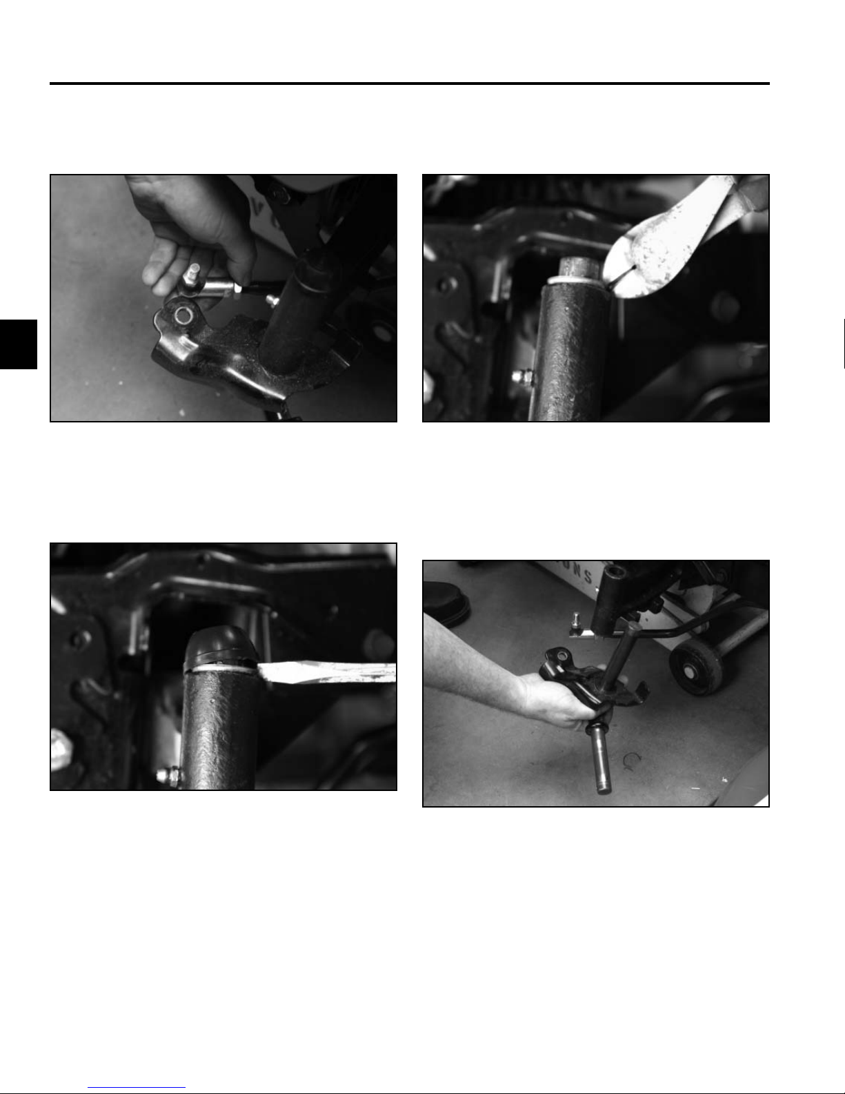
Neutral Adjustment - Hydrostatic
Models
Before making a neutral adjustment, the transmission
must be warmed up for at least 10 minutes.
1. Loosen the bolt and washer retaining the right side
wheel to the right side axle (Fig. 323).
Fig 323 PICT-7221
3. Remove the bolt, washer and wheel assembly from
the right axle (Fig. 324).
Fig 324 PICT-7597
4. Locate the neutral adjusting puck and loosen the
Allen head bolt. If it’s diffi cult to loosen, heat the
aluminum housing near the bolt with a propane torch
(Fig. 325).
2. Raise and support the right rear end of the tractor to
permit removing the right rear tire. Make sure the left
rear tire stays on the ground.
A
Fig 325 PICT-7599
A. Adjusting puck
3-84 LX Lawn Tractor Service Manual
Page 99

CHASSIS
5. Start the engine and run it at full throttle.
6. Rotate the adjusting puck in both directions and
watch the axle direction. Adjust the puck so it is set
at the midpoint between forward and reverse axle
rotation. Make sure the axle is not moving.
7. Once in neutral, hold the puck with an adjustable
wrench so it won’t move. Tighten the Allen head bolt
(Fig. 326).
Front Wheel Toe-in Measurement
If there is uneven tire wear, lawn scuffi ng, or hard steer-
ing, toe-in may need to be adjusted. The front toe-in
measurement should be 1/16” to 5/16” (1.58 to 7.93mm).
This should be checked every 100 hours or once a year,
whichever occurs fi rst.
MEASUREMENT:
1. Disengage the PTO, set the parking brake, and turn
the ignition key to OFF to stop the engine. Remove
the key.
2. Pull the front of the tires out to remove normal looseness in the linkage (Fig. 327).
3
Fig 326 PICT-7600
8. Operate the foot control in forward and reverse.
Allow the pedal to return to the neutral position to
test the adjustment.
Fig 327 PICT-7820
3-85LX Lawn Tractor Service Manual
Page 100

CHASSIS
3
3. Measure the distance between the front rims at
steering axle level (front and rear of the wheels).
Note: You can also measure between the tread mold
marks if the tires are new (Fig. 328 - front and
Fig. 329 - rear).
Fig 328 PICT-7821
Front Wheel Toe-in Adjustment
1. Remove the tie rod from one steering arm (Fig. 330).
Fig 330 PICT-7830
Fig 329 PICT-7828
4. The front measurement should be 1/16” to 5/16”
(1.58mm to 7.93mm) less than the rear measurement. If needed, follow the adjustment procedures:
2. Loosen the jam nut securing the ball joint to the
steering rod (Fig. 331).
Fig 331 PICT-7831
3-86 LX Lawn Tractor Service Manual
 Loading...