

FormNo.3401-570RevC
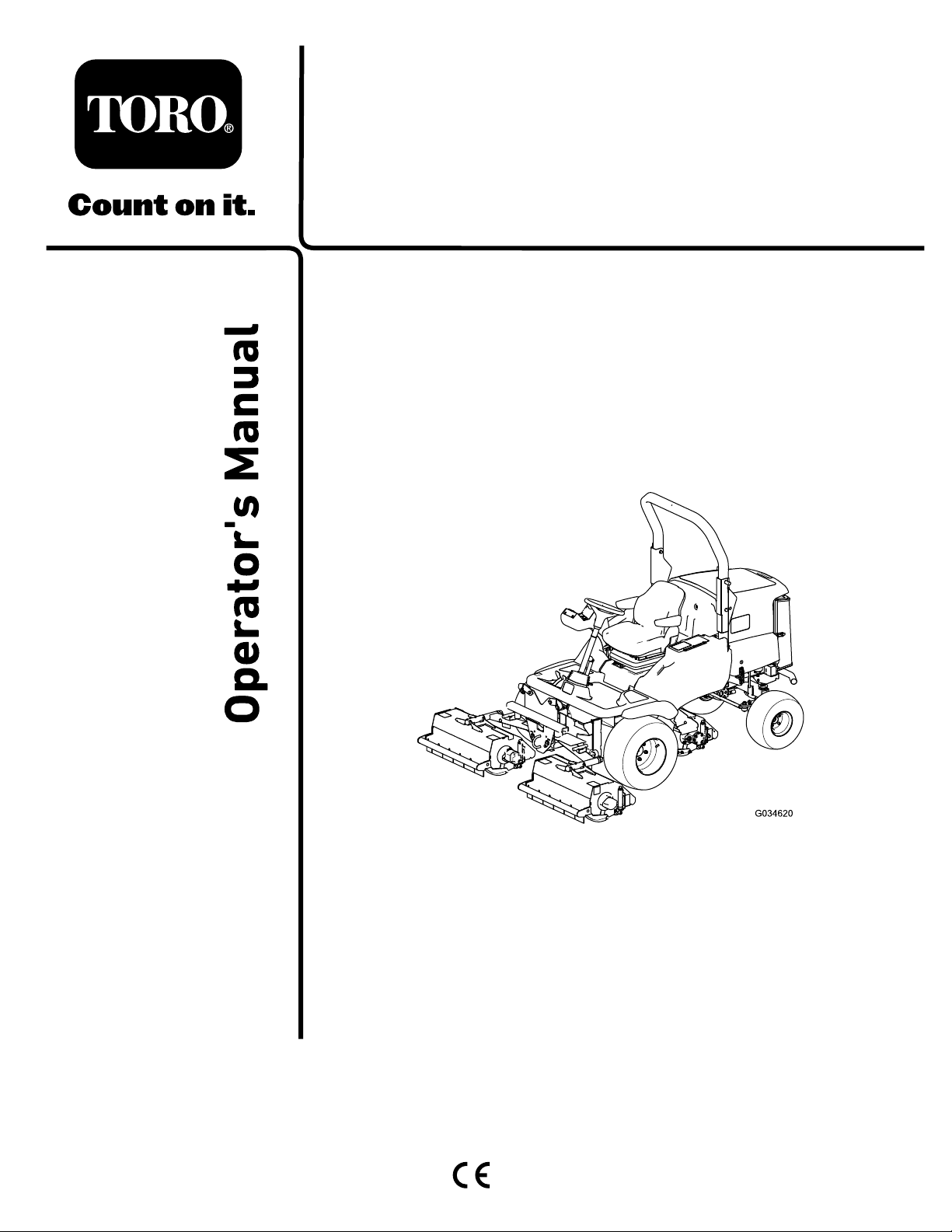
LT-F3000Heavy-DutyTripleTurf
FlailMower
ModelNo.30659—SerialNo.316000001andUp
Registeratwww.T oro.com.
OriginalInstructions(EN)
*3401-570*C
ThisproductcomplieswithallrelevantEuropean
directives.Fordetails,pleaseseetheseparate
productspecicDeclarationofConformity(DOC)
sheet.
Thismanualidentiespotentialhazardsandhas
safetymessagesidentiedbythesafetyalertsymbol
(Figure2),whichsignalsahazardthatmaycause
seriousinjuryordeathifyoudonotfollowthe
recommendedprecautions.
Introduction
Thismachineisaride-onlawnmowerintendedtobe
usedbyprofessional,hiredoperatorsincommercial
applications.Itisprimarilydesignedforcuttinggrass
onparks,sportselds,caravanparks,cemeteries,
andcommercialgrounds.Itisdesignedforcutting
longandshortgrass.
Readthisinformationcarefullytolearnhowtooperate
andmaintainyourproductproperlyandtoavoid
injuryandproductdamage.Youareresponsiblefor
operatingtheproductproperlyandsafely .
Visitwww.Toro.comformoreinformation,including
safetytips,trainingmaterials,accessoryinformation,
helpndingadealer,ortoregisteryourproduct.
Wheneveryouneedservice,genuineToroparts,or
additionalinformation,contactanAuthorizedService
DealerorToroCustomerServiceandhavethemodel
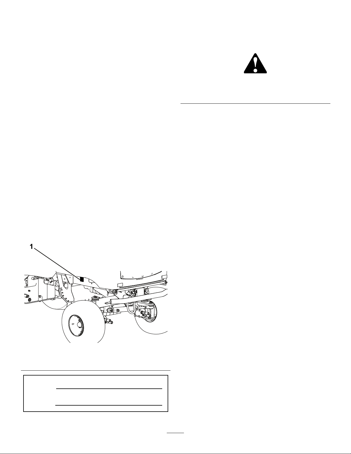
andserialnumbersofyourproductready.Figure1
identiesthelocationofthemodelandserialnumbers
ontheproduct.Writethenumbersinthespace
provided.
g000502
Figure2
Safety-alertsymbol
Thismanualuses2wordstohighlightinformation.
Importantcallsattentiontospecialmechanical
informationandNoteemphasizesgeneralinformation
worthyofspecialattention.
1.Locationofthemodelandserialnumbers
ModelNo.
SerialNo.
©2019—TheToro®Company
8111LyndaleAvenueSouth
Bloomington,MN55420
Figure1
g281378
Contactusatwww.Toro.com.
2
PrintedintheUK
AllRightsReserved

Contents
Safety.......................................................................4
GeneralSafety...................................................4
SafetyandInstructionalDecals..........................4
Setup......................................................................10
ProductOverview...................................................10
Controls............................................................11
Specications..................................................19
Attachments/Accessories.................................19
BeforeOperation.................................................20
BeforeOperationSafety...................................20
PerformingDailyMaintenance..........................20
FillingtheFuelTank..........................................20
DuringOperation.................................................21
DuringOperationSafety...................................21
UsingtheOperatorPlatformLatching
Mechanism...................................................22
UnderstandingtheOperatorPresence
Controls........................................................22
FoldingtheRollBar..........................................23
CheckingtheInterlockSwitches.......................24
StartingtheEngine...........................................24
ShuttingOfftheEngine.....................................25
FlailCuttingUnitGeneralInformation...............25
AdjustingtheHeightofCut...............................25
ControllingthePositionoftheIndividual
CuttingUnits.................................................26
UsingtheCuttingUnitAuto-LimitedLiftin
Reverse........................................................26
EngagingtheCuttingUnitDrive........................27
UsingWeight-Transfer/Traction
Assistance....................................................27
OperatingTips.................................................28
AfterOperation....................................................28
AfterOperationSafety......................................28
IdentifyingtheTie-DownPoints........................29
HaulingtheMachine.........................................29
LocatingtheJackingPoints..............................29
TowingtheMachine..........................................29
Maintenance...........................................................32
MaintenanceSafety..........................................32
RecommendedMaintenanceSchedule(s)...........33
DailyMaintenanceChecklist.............................35
Lubrication..........................................................36
GreasingtheBearings,Bushings,and
Pivots............................................................36
EngineMaintenance...........................................36
EngineSafety...................................................36
CheckingtheEngineOverheatWarning
System..........................................................36
ServicingtheAirCleaner..................................37
CheckingtheEngine-OilLevel..........................38
ServicingtheEngineOilandFilter....................38
FuelSystemMaintenance...................................39
DrainingtheFuelT ank......................................39
CheckingtheFuelLinesand
Connections..................................................39
BleedingtheFuelSystem.................................39
ReplacingtheFuelFilter...................................40
ElectricalSystemMaintenance...........................41
ElectricalSystemSafety...................................41
CheckingtheElectricalSystem.........................41
CheckingtheBatteryCondition.........................41
ServicingtheBattery.........................................41
DriveSystemMaintenance..................................42
CheckingtheTirePressure...............................42
CheckingtheT orqueoftheWheel-Lug
Nuts..............................................................42
ChangingtheTransmissionOilFilter................42
ChangingtheHydraulic-ReturnFilter................42
CheckingtheRear-WheelAlignment................43
InspectingtheTransmissionControlCable
andOperatingMechanism............................43
CoolingSystemMaintenance..............................44
CoolingSystemSafety.....................................44
RemovingDebrisfromtheCooling
System..........................................................44
BeltMaintenance................................................45
TensioningtheAlternatorBelt...........................45
ControlsSystemMaintenance.............................46
CheckingtheForward/ReverseTravelPedal
Action............................................................46
CheckingtheOperator-Presence-Seat
Switch...........................................................46
CheckingtheCutter-Drive-Interlock
Switch...........................................................46
CheckingtheParking-Brake-Interlock
Switch...........................................................46
CheckingtheTransmission-Neutral-Interlock
Switch...........................................................46
HydraulicSystemMaintenance...........................47
HydraulicSystemSafety...................................47
CheckingtheHydraulicLinesand
Hoses............................................................47
CheckingtheHydraulicFluid............................47
ServicingtheHydraulicSystem........................48
CheckingtheHydraulic-Fluid-Overheat
WarningSystem............................................48
CuttingUnitMaintenance.....................................49
BladeSafety.....................................................49
ReplacingtheBlades........................................49
CheckingtheBladeBolts..................................49
InspectingtheBlades.......................................49
CheckingtheRearGuard.................................50
ClearingaBlockedRotor..................................50
CheckingtheRubberGuard.............................51
CheckingtheCuttingUnitPivot.........................51
CheckingtheRotor...........................................51
CheckingtheRear-RollerBearing
Adjustment....................................................51
CheckingtheRear-RollerScraperWire
Tension.........................................................52
Cleaning..............................................................52
WashingtheMachine.......................................52
Storage...................................................................53
3
StorageSafety..................................................53
PreparingtheTractionUnit...............................53
PreparingtheEngine........................................53
Troubleshooting......................................................54
Safety
Thismachinehasbeendesignedinaccordancewith
ENISO5395.
GeneralSafety
Thisproductiscapableofamputatinghandsandfeet
andofthrowingobjects.
•Readandunderstandthecontentsofthis
Operator’sManualbeforestartingtheengine.
•Useyourfullattentionwhileoperatingthe
machine.Donotengageinanyactivitythat
causesdistractions;otherwise,injuryorproperty
damagemayoccur.
•Donotputyourhandsorfeetnearmoving
componentsofthemachine.
•Donotoperatethemachinewithoutallguards
andothersafetyprotectivedevicesinplaceand
functioningproperlyonthemachine.
•Keepbystandersandchildrenoutoftheoperating
area.Neverallowchildrentooperatethemachine.
SafetyandInstructionalDecals
Safetydecalsandinstructionsareeasilyvisibletotheoperatorandarelocatednearanyarea
ofpotentialdanger.Replaceanydecalthatisdamagedormissing.
•Shutofftheengine,removethekey,andwait
forallmovementtostopbeforeyouleavethe
operator’sposition.Allowthemachinetocool
beforeadjusting,servicing,cleaning,orstoringit.
Improperlyusingormaintainingthismachinecan
resultininjury .Toreducethepotentialforinjury,
complywiththesesafetyinstructionsandalways
payattentiontothesafety-alertsymbol
meansCaution,Warning,orDanger—personalsafety
instruction.Failuretocomplywiththeseinstructions
mayresultinpersonalinjuryordeath.
,which
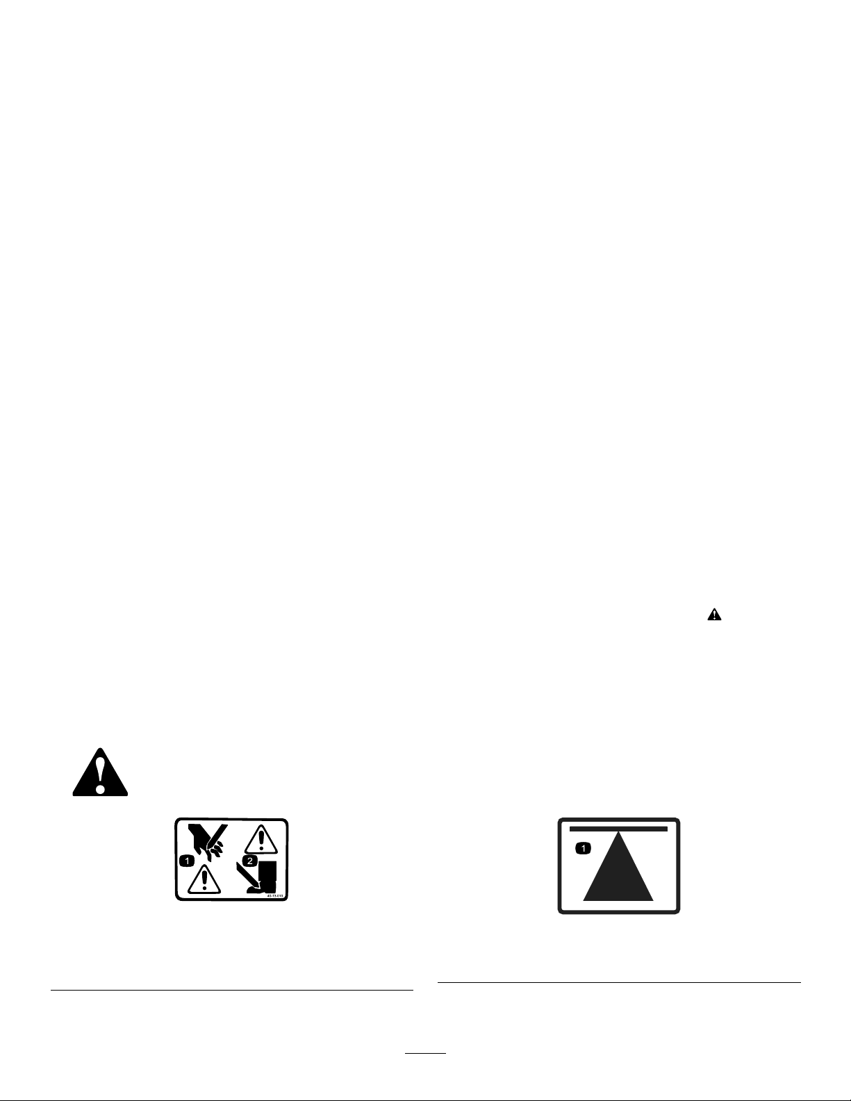
1.Cuttinghazardofhand
2.Cuttinghazardoffoot
decal40-13-010
40-13–010
70-13-072
1.Jackingpoint
4
decal70-13-072
70-13-077
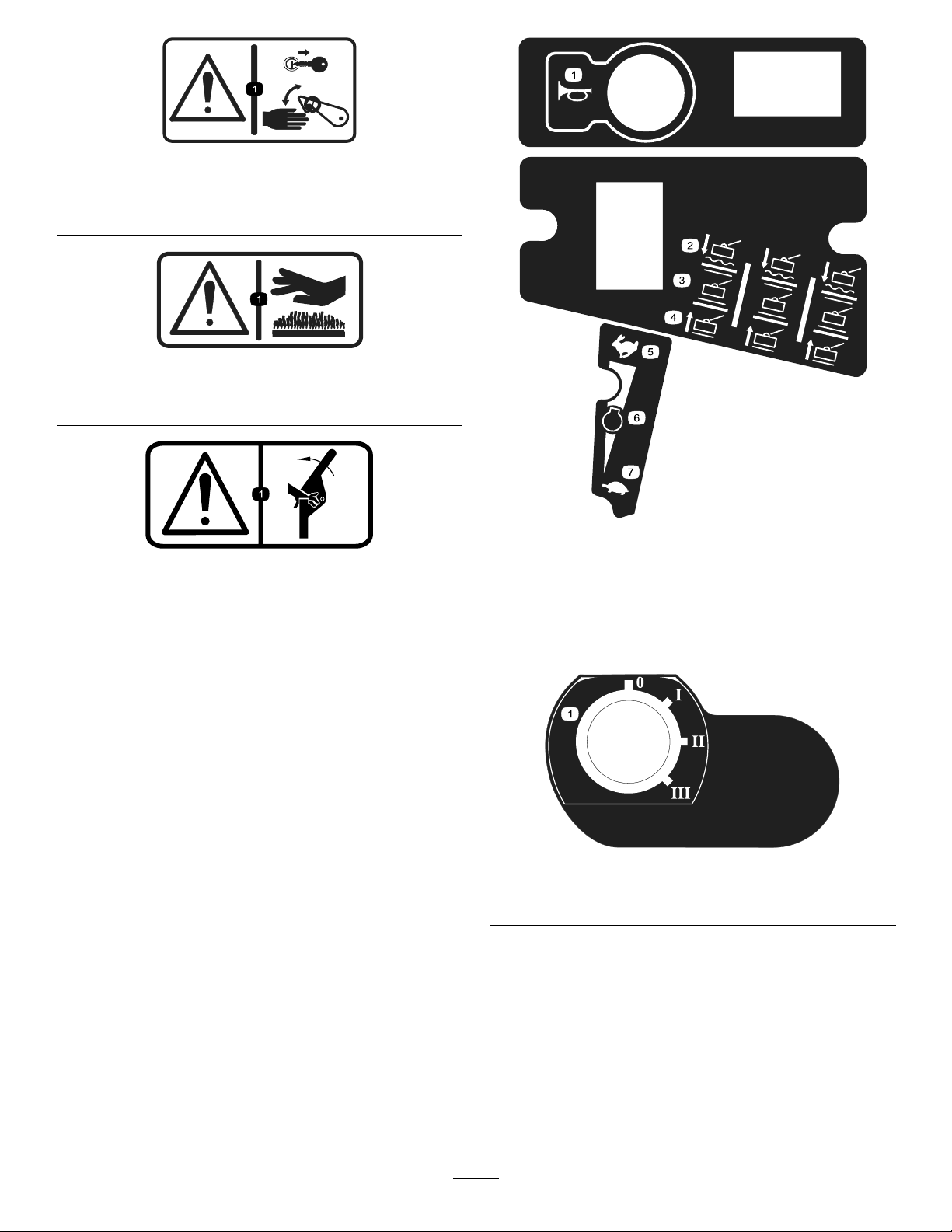
1.Warning—shutofftheengineandremovetheignitionkey
beforereleasingoroperatingsafetylatches.
950889
1.Warning—hotsurfaces.
111-0773
1.Warning—crushingofngers,forceappliedfromside.
decal70-13-077
decal950889
decal11 1-3277
111-3277
decal11 1-0773
1.Horn5.Fast
2.Cuttingunits—lower/oat
3.Cuttingunits—hold
4.Cuttingunits—raise
6.Enginespeed
7.Slow
decal11 1-3344
111-3344
1.Ignitionswitch
5
111-3562
1.Pressthepedaltoadjustthesteeringwheelangle.
decal11 1-3562
decal11 1-3658
111-3658
111-3566
1.Falling,crushinghazard—ensurethattheoperator-platform
latchisengagedbeforeoperating.
111-3567
1.Pedaloperation
1.Cutterhead
3.Unlatch
2.Latch
decal11 1-3566
decal11 1-3901
111-3901
1.Transmissionuid—readtheOperator'sManual.
decal11 1-3902
111-3902
decal11 1-3567
1.Yourhandcanbecutbythefan;warning
2.Hotsurfaces;readtheOperator'sManual.
6
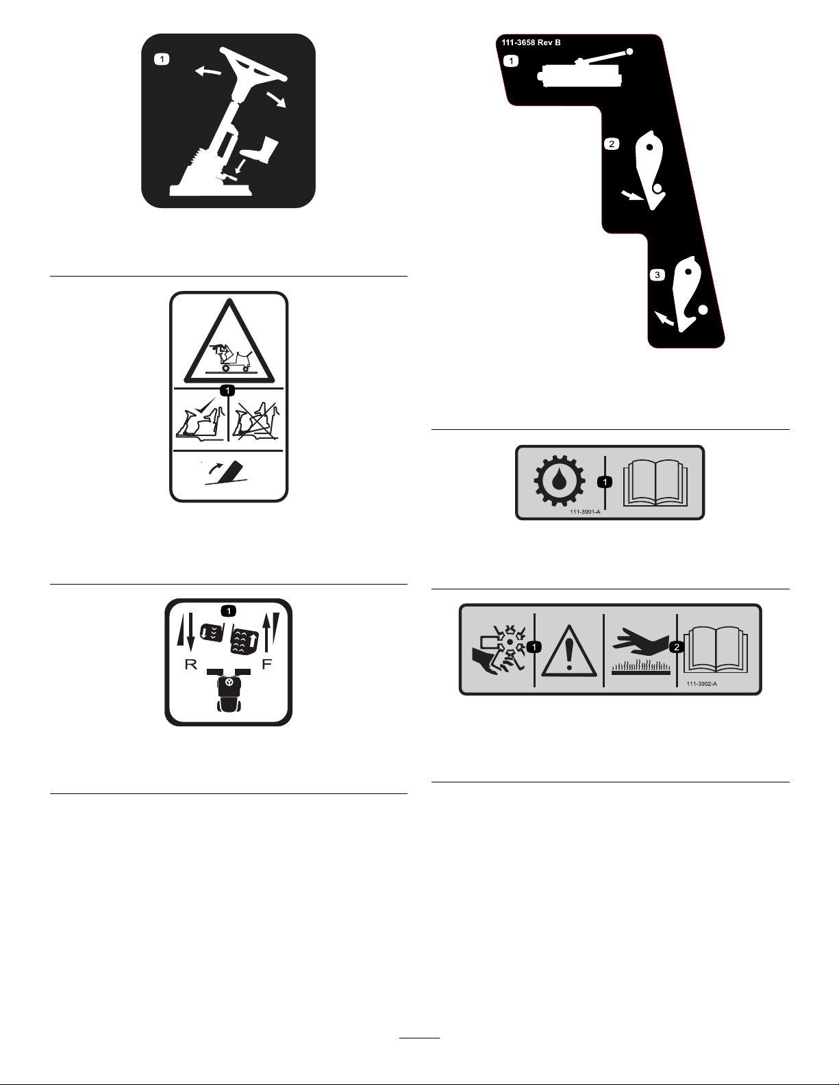
1.Height-of-cutchart
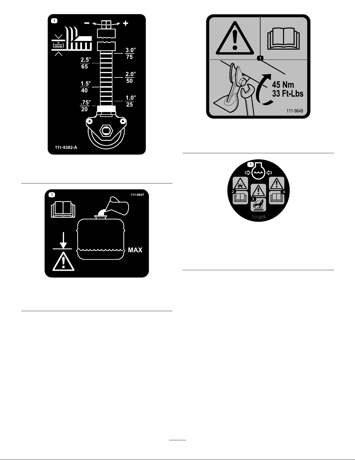
decal11 1-9648
111-9648
1.Warning—readtheOperator'sManual;torquethenutsto
45N∙m(33ft-lb).
decal11 1-9382
111-9382
decal117-3276
117-3276
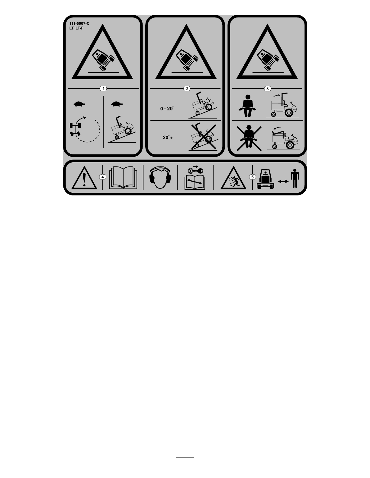
111-9647
1.ReadtheOperator'sManual—lltothemaximumlevel;
donotoverll.
1.Enginecoolantunder
pressure
2.Explosionhazard—read
theOperator'sManual.
decal11 1-9647
3.Warning—donottouchthe
hotsurface.
4.Warning—readthe
Operator'sManual.
7
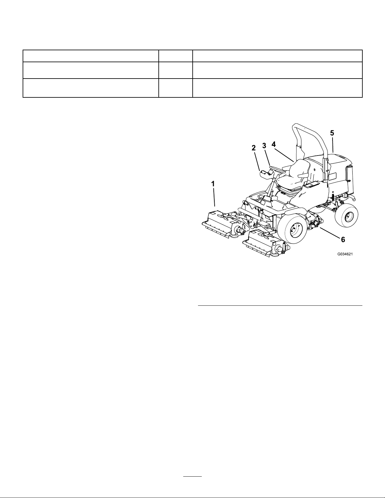
111-5007
Note:Thismachinecomplieswiththeindustrystandardstabilitytestinthestaticlateralandlongitudinaltestswiththemaximum
recommendedslopeindicatedonthedecal.ReviewtheinstructionsforoperatingthemachineonslopesintheOperator’sManualas
wellastheconditionsinwhichyouwouldoperatethemachinetodeterminewhetheryoucanoperatethemachineintheconditions
onthatdayandatthatsite.Changesintheterraincanresultinachangeinslopeoperationforthemachine.Ifpossible,keepthe
cuttingunitsloweredtothegroundwhileoperatingthemachineonslopes.Raisingthecuttingunitswhileoperatingonslopescan
causethemachinetobecomeunstable.
decal11 1-5007
1.Tippinghazard—driveslowlywhenturningorgoingupslopes.
2.Tippinghazard—onlydriveupslopesthatarebetween0and
20°;donotdriveupslopesthataregreaterthan20°.
3.Tippinghazard—wearaseatbeltwhentherollbarisup;donot
wearaseatbeltwhentherollbarisdown.
4.Warning—readtheOperator'sManual;wearhearing
protection;removethekeybeforeperformingany
maintenance.
5.Thrownobjecthazard—keepbystandersaway .
8

decal11 1-9649
111-9649
1.ReadtheOperator'sManualformoreinformationonservice
8.Ensurethebladesstopwhenyouleavetheoperatingposition.
andmaintenance.
2.Tirepressure—1bar(14.5psi)9.Checktheairlter.
3.Checkallfasteners.10.Inspectthebladesforwear.
4.Checkforhydraulicleaks.11.Ensurethebottleislledtothelowline.
5.Checkthetransmission-oillevel.12.Cleanthecoolingsystem.
6.Checkthefuellevel.13.Cleanthemachineandtorquethefrontwheelto200N∙m
andtherearwheelto54N∙m.
7.Checktheoillevel.
9
Setup
MediaandAdditionalParts
Description
Operator'sManual
Engineowner’smanual1
DeclarationofConformity
Note:Determinetheleftandrightsidesofthe
machinefromthenormaloperatingposition.
Qty.
Use
1
1
Readthemanualsbeforeoperatingthemachine.
TheDeclarationofConformityservesasconrmationof
CEcompliance.
ProductOverview
1.Frontcuttingunits
2.Controlarm
3.Steeringwheel
g034621
Figure3
4.Operator'sseat
5.Enginehood
6.Rearcuttingunit
10
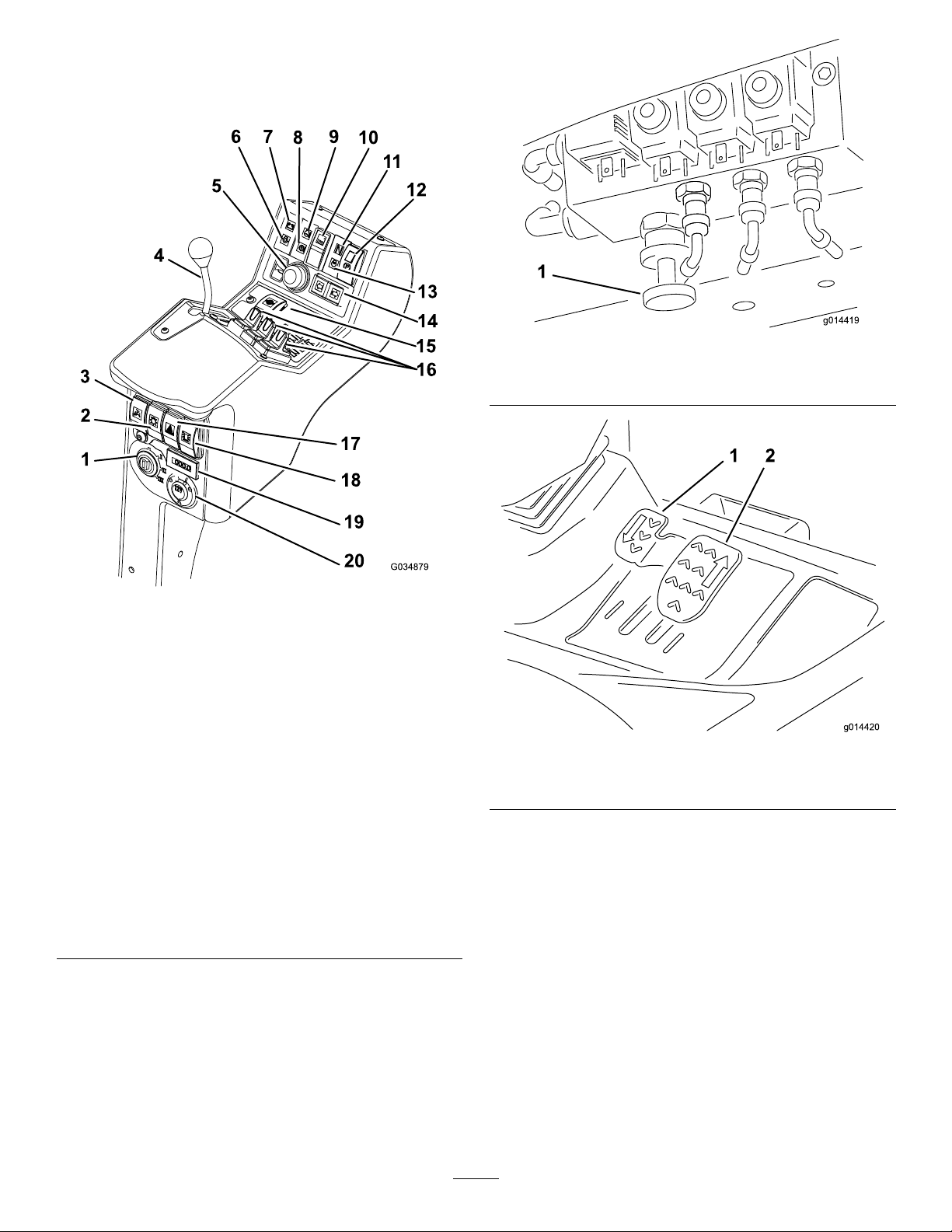
Controls
ControlPanelComponents
g014419
Figure5
1.Weighttransfercontrol
Figure4
1.Ignitionswitch11.Transmission-neutral
2.Lightingswitch(supplied
withlightingkit)
3.Limited-lift-in-reverse
switch
4.Throttle-controllever14.Direction-indicatorswitch
5.Hornbutton
6.Engine-oil-warninglight
7.Battery-charge-warning
light
8.Hydraulic-uid-warning
light
9.Engine-coolant-warning
light
10.Cutting-unit-driveswitch
indicator
12.Parking-brakeswitch
13.Engine-preheat-indicator
light
(suppliedwithlightingkit)
15.Differential-lockswitch
16.Lift-controlswitches
17.Hazard-warningswitch
(suppliedwithlightingkit)
18.Warning-beaconswitch
(suppliedwithbeaconkit)
19.Hourmeter
20.Auxiliary12Vsocket
g034879
g014420
Figure6
1.Reversetravelpedal2.Forwardtravelpedal
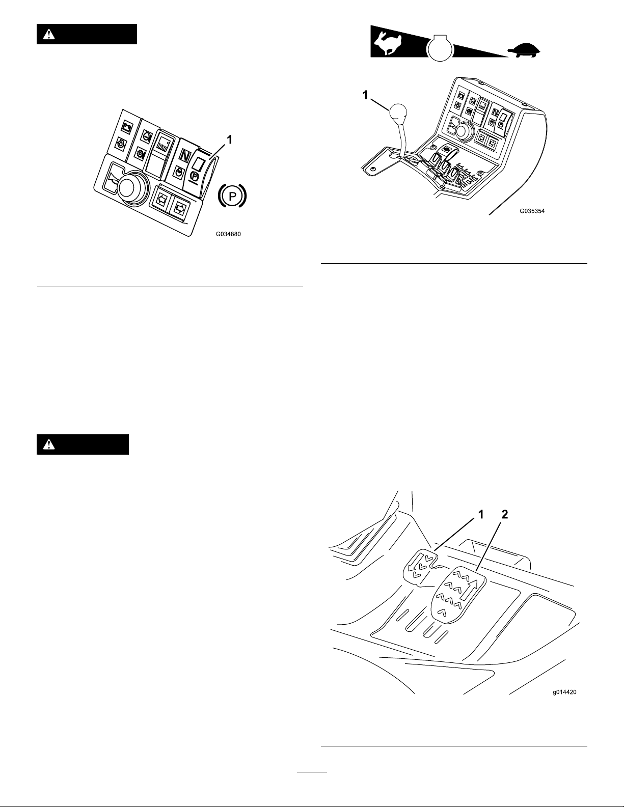
BrakingSystem
ParkingBrake
Movetheparking-brakeswitchtotheforwardposition
bypressingthesmallerlockingbuttonandmovingthe
switchforwardtoengagetheparkingbrake(Figure7).
Note:Donotoperatethemowerwiththeparking
brakeengagedanddonotengagetheparkingbrake
whilethemowerismoving.
Thislightilluminateswhentheparkingbrakeis
engagedandtheignitionkeyisturnedtopositionI.
11
WARNING
Theparkingbrakeoperatesonthefront
wheelsonly.
Donotparkthemachineonaslope.
Figure7
1.Parking-brakeswitch
g035354
Figure8
g034880
1.Throttle-controllever
Travel
ServiceBrake
Servicebrakingisachievedbythehydraulic
transmissionsystem.Whentheforwardorreverse
travelpedalsarereleasedortheenginespeedis
reduced,servicebrakingbecomeseffectiveandtravel
speedisautomaticallyreduced.Toincreasethe
brakingeffect,pushthetransmissionpedalintothe
NEUTRALposition.Servicebrakingiseffectiveonthe
frontwheelsonly.
DANGER
Theservicebrakingsystemdoesnotholdthe
moweratastandstill.
Alwaysensurethattheparkingbrakeis
engagedtoparkthemoweratastandstill.
EmergencyBrake
Intheeventofservicebrakefailure,turntheignition
offtobringthemowertoastandstill.
ThrottleControl
Forwardtravel:Presstheforwardtravelpedalto
increaseforwardtravelspeed.Releasethepedalto
reducespeed(Figure9).
Reversetravel:Pressthereversetravelpedalto
increasereversetravelspeed.Releasethepedalto
reducespeed(Figure9).
Stop(Neutral):T ostopthemachine,use1ofthe
followingprocedures:
•Reduceyourfootpressureonthetractionpedal
andallowittoreturntotheneutralposition.The
machinedynamicallybrakestoasmoothstop.
•Taporholdthereversepedalbriey .Thisstops
themachinefasterthandynamicbraking.
Operatethethrottlecontrolinaforwarddirection
toincreasetheenginespeed.Operatethethrottle
controlinarearwarddirectiontoreduceenginespeed
(Figure8).
Note:Theenginespeeddictatesthespeedofthe
otherfunctions,i.e.,travel,ail-rotorrotationspeed,
andcuttingunitliftspeed.
g014420
Figure9
1.Reversetravelpedal2.Forwardtravelpedal
12
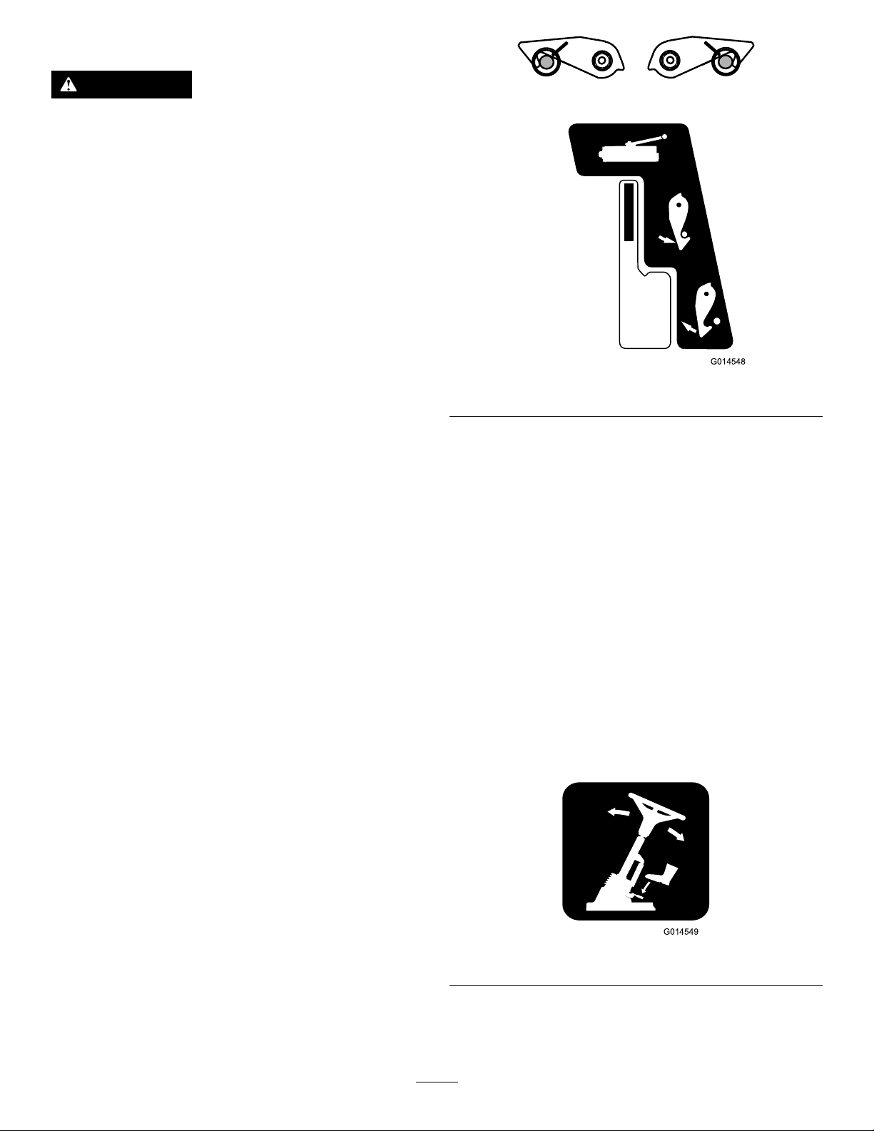
DifferentialLock
WARNING
Theturningradiusincreaseswhenthe
differentiallockisengaged.Usingthe
differentiallockathighspeedmayleadtoloss
ofcontrolandcauseseriousinjuryand/or
propertydamage.
Donotusethedifferentiallockathighspeed.
Usethedifferentiallocktopreventexcessivewheel
spinwhenthedrivewheelslosetraction.The
differentiallockoperatesinbothforwardandreverse.
Youcanlockthedifferentialwhilethemachineis
travelingslowly.Enginepowerdemandincreases
whenthedifferentialislocked.Preventexcessive
powerrequirementsbyusingthedifferentiallockonly
atlowspeed.
Tolockthedifferential,pressthedifferential-lock
switch.
g014548
Figure10
Tounlockthedifferential,releasethedifferential-lock
switch.
Cutting-UnitsPositionControls
Usethecutting-unitspositioncontrolstoindependently
raiseandlowerthecuttingunits;refertoControlling
thePositionoftheIndividualCuttingUnits(page26).
TransportLatches
AlwaysraisethecuttingunitstotheTRANSPORT
positionandsecurewiththetransportlatchesand
safetylockswhentravellingbetweenworkareas
(Figure10).
Cutting-Unit-DriveSwitch
Toengagethecuttingunitdrive,refertoEngagingthe
CuttingUnitDrive(page27).
Note:Alwaysputthecutting-unit-driveswitchinthe
OFFpositionwhentravellingbetweenworkareas.
AdjustableSteeringColumn
Adjustmentofthesteeringwheelandsteeringcolumn
shouldonlybecarriedoutwhenthemowerisata
standstillwiththeparkingbrakeengaged.
1.Totiltthesteeringwheel,pressthefootpedal
down.
2.Positionthesteeringtowertothemost
comfortablepositionandreleasethepedal
(Figure1 1).
g014549
Figure11
13
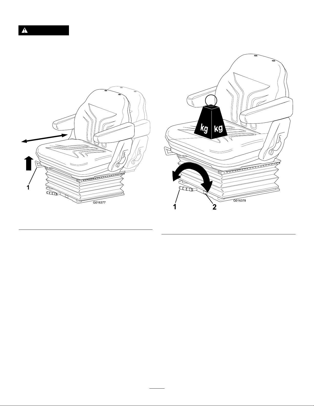
OperatorSeat
WARNING
Ensurethattheoperator-platformlatchis
engagedbeforeoperatingthemachine.
•Forward/BackwardAdjustment:Movethelever
upwardtoadjusttheforward/backwardposition
oftheseat.Releasethelevertolocktheseatin
position(Figure12).
•Operatorweightadjustment:Rotatethehandle
clockwisetoincreasesuspensionstiffnessand
counterclockwisetodecreasethestiffness.The
dialindicateswhentheoptimumsuspension
adjustmenthasbeensetaccordingtooperator
weight(kg);refertoFigure13.
g016377
Figure12
Figure13
1.Lever
1.Lever2.Dial
g016378
14
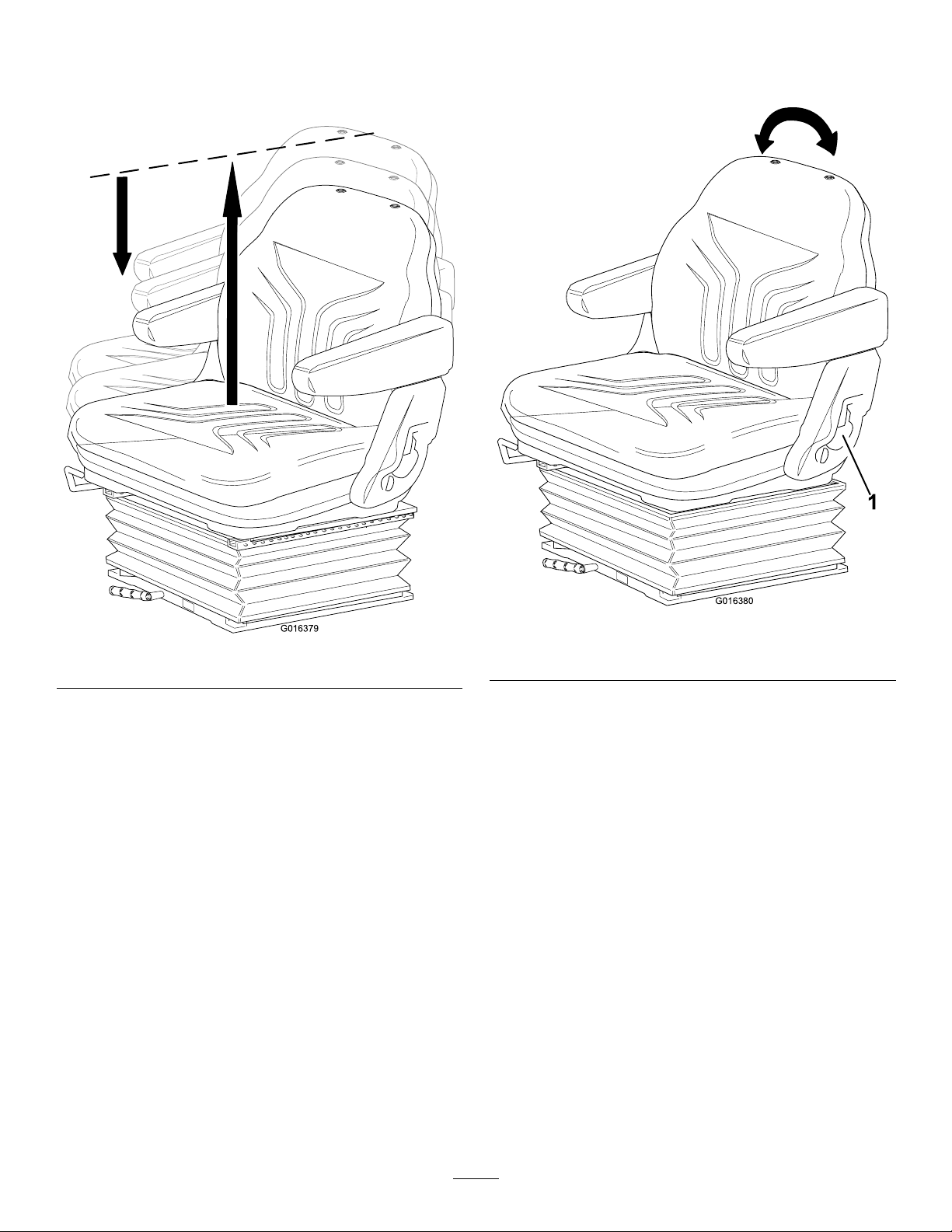
•Heightadjustment:Manuallylifttheseatfor
incrementalheightadjustment.T olowertheseat,
liftitbeyondthehighestsetting,thenallowitto
droptothelowestsetting(Figure14).
•Backrestadjustment:Pullthehandleoutwardto
adjusttheseatbackrestangle.Releasethehandle
tolocktheseatbackrestinposition(Figure15).
Figure14
g016380
g016379
1.Handle
Figure15
15
WarningSystems
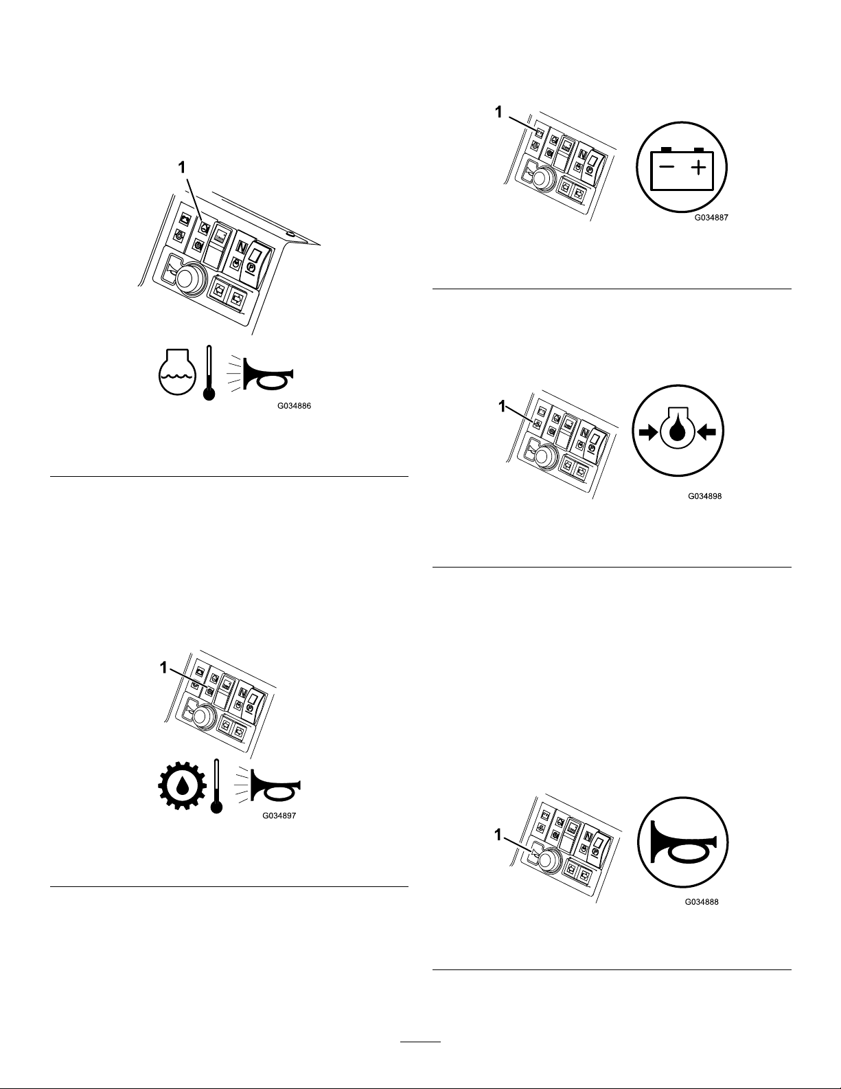
Battery-Charge-WarningLight
Engine-Coolant-Temperature-WarningLight
Theengine-coolant-temperature-warninglight
illuminates,thehornisactuated,andthecuttingunits
stopwhentheenginebecomestoohot(Figure16).
Figure16
1.Engine-coolant-temperature-warninglight
Thebattery-charge-warninglightilluminateswhenthe
batteryislowofcharge(Figure18).
g034887
Figure18
1.Battery-charge-warninglight
Engine-Oil-Pressure-WarningLight
Theengine-oil-pressure-warninglightilluminates
whentheoilpressureistoolow(Figure19).
g034886
Note:Theailrotorsdisengagewhentheoperating
temperaturereaches1 15°C(239°F).
Hydraulic-Fluid-Temperature-WarningLight
Thehydraulic-uid-temperature-warninglight
illuminateswhenoverheatingoccursandthehorn
isactuatedwhenthehydraulicuidinthereservoir
exceeds95°C(203°F);refertoFigure17.
Figure17
1.Hydraulic-uid-temperature-warninglight
g034898
Figure19
1.Engine-oil-pressure-warninglight
AudibleWarningHorn
ServiceInterval:Beforeeachuseordaily—Check
thehorn.
Pressthehornbuttontoprovideanaudiblewarning
(Figure20).
Important:Thehornisautomaticallyactuated
whenanenginecoolantorhydraulicuidoverheat
conditionoccurs.Shutofftheengineimmediately
andxthemachinebeforestartingitagain.
g034897
g034888
Figure20
1.Horn
16
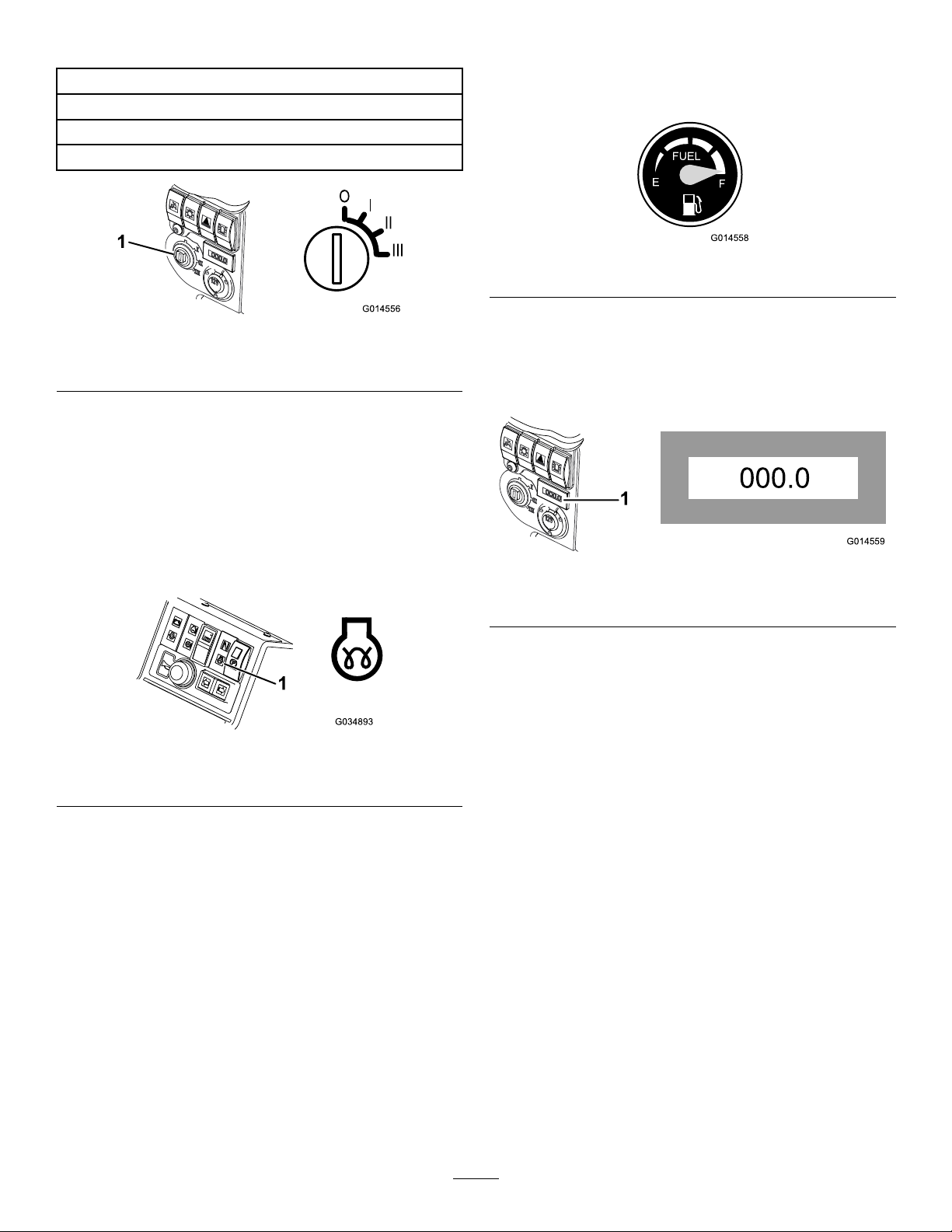
KeySwitch
FuelGauge
0=Engineoff
I=Enginerun/Auxiliaryon
II=Enginepre-heat
III=Enginestart
Figure21
1.Keyswitch
EnginePre-HeatIndicatorLight
TurnthekeytopositionII.Theenginepreheat
indicatorlightwillilluminateandheattheglowplugs
(Figure22).
Thefuelgaugeshowstheamountoffuelinthetank
(Figure23).
g014558
Figure23
g014556
HourMeter
Thehourmetershowsthetotalhoursthatthemachine
hasbeenoperated(Figure24).
Important:Attemptingtostartacoldengine
beforethepre-heatisusedcancauseunnecessary
weartothebattery.
Figure22
1.Enginepre-heatindicatorlight
g014559
Figure24
1.Hourmeter
Transmission-Neutral-Indicator
Light
g034893
Thislightilluminateswhenthetravel-controlpedalis
intheNEUTRALpositionandtheignitionkeyisturned
topositionI(Figure25).
Note:Theparkingbrakemustbeengagedforthe
transmissionneutralindicatorlighttoilluminate.
17

Cutting-Unit-Drive-Switch-Indicator
Light
Thislightilluminateswhenthecuttingunitdriveswitch
isOnandtheignitionkeyisturnedtopositionI(Figure
26).
Figure25
1.Transmission-neutral-indicatorlight
g034894
Toengagethecuttingunitdrive,refertoEngagingthe
CuttingUnitDrive(page27).
g034895
Figure26
1.Cutting-unit-drive-switch-indicatorlight
18

Specications
Note:Specicationsanddesignaresubjecttochangewithoutnotice.
Specication
TransportWidth
Widthofcut76cm(30inches)to212cm(83.5inches)
Heightofcut20mm(3/4inch)to75mm(3inches)
Length
Height
Weight
Engine
Fueltankcapacity
Transportspeed
Mowingspeed
Kubota32.8kw(44hp)at3000rpmDIN70020
302.5cm(1 19.1inches)
216cm(85.0inches)withROPS
209cm(82.3inches)withcab
1392kg(3069lb)withROPS
1592kg(3510lb)withcab
LT -F3000
157.5cm(62inches)
45L(1 1.9USgallons)
25km/h(15.5mph)
11km/h(6.85mph)
Hydraulicsystemcapacity
Enginespeed3000rpm
Rotorspeed3000rpm
32L(8.5USgallons)
Attachments/Accessories
AselectionofT oroapprovedattachmentsand
accessoriesisavailableforusewiththemachine
toenhanceandexpanditscapabilities.Contact
yourAuthorizedServiceDealerorauthorizedT oro
distributororgotowww.Toro.comforalistofall
approvedattachmentsandaccessories.
Toensureoptimumperformanceandcontinuedsafety
certicationofthemachine,useonlygenuineT oro
replacementpartsandaccessories.Replacement
partsandaccessoriesmadebyothermanufacturers
couldbedangerous,andsuchusecouldvoidthe
productwarranty.
19

Operation
PerformingDaily
Maintenance
BeforeOperation
BeforeOperationSafety
GeneralSafety
•Neverallowchildrenoruntrainedpeopleto
operateorservicethemachine.Localregulations
mayrestricttheageoftheoperator.Theowner
isresponsiblefortrainingalloperatorsand
mechanics.
•Becomefamiliarwiththesafeoperationofthe
equipment,operatorcontrols,andsafetysigns.
•Shutofftheengine,removethekey,andwait
forallmovementtostopbeforeyouleavethe
operator’sposition.Allowthemachinetocool
beforeadjusting,servicing,cleaning,orstoringit.
•Knowhowtostopthemachineandshutoffthe
enginequickly.
•Donotoperatethemachinewithoutallguards
andothersafetyprotectivedevicesinplaceand
functioningproperlyonthemachine.
ServiceInterval:Beforeeachuseordaily
Beforestartingthemachineeachday ,performthe
EachUse/DailyprocedureslistedinMaintenance
(page32).
FillingtheFuelTank
FuelTankCapacity
45L(11.9USgallons)
FuelSpecication
Failuretoobservethefollowingcautionsmaydamage
theengine.
•Neverusekeroseneorgasolineinsteadofdiesel
fuel.
•Nevermixkeroseneorusedengineoilwiththe
dieselfuel.
•Neverkeepfuelincontainerswithzincplatingon
theinside.
•Donotusefueladditives.
•Beforemowing,alwaysinspectthemachineto
ensurethatthecuttingunitsareingoodworking
condition.
•Inspecttheareawhereyouwillusethemachine
andremoveallobjectsthatthemachinecould
throw.
FuelSafety
•Useextremecareinhandlingfuel.Itisammable
anditsvaporsareexplosive.
•Extinguishallcigarettes,cigars,pipes,andother
sourcesofignition.
•Useonlyanapprovedfuelcontainer.
•Donotremovethefuelcaporllthefueltank
whiletheengineisrunningorhot.
•Donotaddordrainfuelinanenclosedspace.
•Donotstorethemachineorfuelcontainerwhere
thereisanopename,spark,orpilotlight,such
asonawaterheaterorotherappliance.
•Ifyouspillfuel,donotattempttostarttheengine;
avoidcreatinganysourceofignitionuntilthefuel
vaporshavedissipated.
PetroleumDiesel
Useonlyclean,freshdieselfuelorbiodieselfuelswith
low(<500ppm)orultra-low(<15ppm)sulfurcontent.
Theminimumcetaneratingshouldbe40.Purchase
fuelinquantitiesthatcanbeusedwithin180days
toensurefuelfreshness.
Usesummer-gradedieselfuel(Number2-D)at
temperaturesabove-7°C(20°F)andwinter-grade
dieselfuel(Number1-DorNumber1-D/2-Dblend)
below-7°C(20°F).Usingwinter-gradefuelatlower
temperaturesprovidesalowerashpointand
cold-owcharacteristics,whichwilleasestartingand
reducefuel-lterplugging.
Usingsummer-gradefuelabove-7°C(20°F)will
contributetowardlongerfuel-pumplifeandincreased
powercomparedtowinter-gradefuel.
AddingFuel
1.Parkthemachineonalevelsurface,lowerthe
cuttingunits,engagetheparkingbrake,shutoff
theengine,andremovethekey.
2.Usingacleanrag,cleantheareaaroundthe
fuel-tankcap.
3.Removethecapfromthefueltank.
4.Fillthetankuntilthelevelistothebottomofthe
llerneckwithfuel.
20

5.Installfuel-tankcaptightlyafterllingtank.
–Parkthemachineonalevelsurface.
Note:Ifpossible,llthefueltankaftereachuse.
Thisminimizespossiblebuildupofcondensation
insidethefueltank.
DuringOperation
DuringOperationSafety
GeneralSafety
•Theowner/operatorcanpreventandisresponsible
foraccidentsthatmaycausepersonalinjuryor
propertydamage.
•Wearappropriateclothing,includingeye
protection;longtrousers;substantial,slip-resistant
footwear;andhearingprotection.Tiebacklong
hairanddonotwearlooseclothingorloose
jewelry.
•Donotoperatethemachinewhileill,tired,or
undertheinuenceofalcoholordrugs.
•Useyourfullattentionwhileoperatingthe
machine.Donotengageinanyactivitythat
causesdistractions;otherwise,injuryorproperty
damagemayoccur.
•Beforeyoustarttheengine,ensurethatalldrives
areinneutral,theparkingbrakeisengaged,and
youareintheoperatingposition.
•Donotcarrypassengersonthemachineandkeep
bystandersandchildrenoutoftheoperatingarea.
•Operatethemachineonlyingoodvisibilitytoavoid
holesorhiddenhazards.
•Avoidmowingonwetgrass.Reducedtraction
couldcausethemachinetoslide.
•Keepyourhandsandfeetawayfromthecutting
units.
•Lookbehindanddownbeforebackinguptobe
sureofaclearpath.
•Usecarewhenapproachingblindcorners,shrubs,
trees,orotherobjectsthatmayobscureyour
vision.
•Stopthecuttingunitswheneveryouarenot
mowing.
•Slowdownandusecautionwhenmakingturns
andcrossingroadsandsidewalkswiththe
machine.Alwaysyieldtheright-of-way.
•Operatetheengineonlyinwell-ventilatedareas.
Exhaustgasescontaincarbonmonoxide,which
islethalifinhaled.
•Donotleavearunningmachineunattended.
•Beforeyouleavetheoperator’sposition,dothe
following:
–Disengagethecuttingunit(s)andlowerthe
attachments.
–Engagetheparkingbrake.
–Shutofftheengineandremovethekey .
–Waitforallmovementtostop.
•Operatethemachineonlyingoodvisibilityand
appropriateweatherconditions.Donotoperate
themachinewhenthereistheriskoflightning.
RolloverProtectionSystem
(ROPS)Safety
•DonotremoveanyoftheROPScomponentsfrom
themachine.
•Ensurethattheseatbeltisattachedandthatyou
canreleaseitquicklyinanemergency.
•Alwayswearyourseatbelt.
•Checkcarefullyforoverheadobstructionsanddo
notcontactthem.
•KeeptheROPSinsafeoperatingconditionby
thoroughlyinspectingitperiodicallyfordamage
andkeepingallthemountingfastenerstight.
•ReplacealldamagedROPScomponents.Donot
repairoralterthem.
MachineswithaFoldableRollBar
•Alwaysusetheseatbeltwiththerollbarinthe
raisedposition.
•TheROPSisanintegralsafetydevice.Keepa
foldingrollbarintheraisedandlockedposition,
andusetheseatbeltwhenoperatingthemachine
withtherollbarintheraisedposition.
•Lowerafoldingrollbartemporarilyonlywhen
necessary.Donotweartheseatbeltwhenthe
rollbarisfoldeddown.
•Beawarethatthereisnorolloverprotectionwhen
afoldedrollbarisinthedownposition.
•Checktheareathatyouwillbemowingandnever
folddownafoldingrollbarinareaswherethere
areslopes,drop-offs,orwater.
SlopeSafety
•Slopesareamajorfactorrelatedtolossofcontrol
androlloveraccidents,whichcanresultinsevere
injuryordeath.Y ouareresponsibleforsafeslope
operation.Operatingthemachineonanyslope
requiresextracaution.
•Evaluatethesiteconditionstodetermineifthe
slopeissafeformachineoperation,including
21

surveyingthesite.Alwaysusecommonsense
andgoodjudgmentwhenperformingthissurvey .
•Reviewtheslopeinstructions,listedbelow,for
operatingthemachineonslopes.Beforeyou
operatethemachine,reviewthesiteconditionsto
determinewhetheryoucanoperatethemachine
intheconditionsonthatdayandatthatsite.
Changesintheterraincanresultinachangein
slopeoperationforthemachine.
–Avoidstarting,stopping,orturningthemachine
onslopes.Avoidmakingsuddenchangesin
speedordirection.Maketurnsslowlyand
gradually.
–Donotoperateamachineunderanyconditions
wheretraction,steering,orstabilityisin
question.
–Removeormarkobstructionssuchasditches,
holes,ruts,bumps,rocks,orotherhidden
hazards.T allgrasscanhideobstructions.
Uneventerraincouldoverturnthemachine.
–Beawarethatoperatingthemachineonwet
grass,acrossslopes,ordownhillmaycause
themachinetolosetraction.
ReleasingthePlatform
1.Movethelockinglatchhandletowardsthefront
ofthemoweruntilthelatchhooksclearthe
lockingbar.
2.Raisetheplatform.Thegasspringwillprovide
assistance.
SecuringthePlatform
1.Lowertheplatformcarefully .
Note:Thegasspringwillprovideassistance.
2.Movethelockinglatchhandletowardsthefront
ofthemowerastheplatformnearsthefully
loweredposition.
Note:Thiswillensurethatthelatchhooksclear
thelockingbar.
3.Fullylowertheplatformandmovethelocking
handletowardstherearofthemoweruntilthe
latchhooksfullyengagethelockingbar.
–Useextremecautionwhenoperating
themachineneardrop-offs,ditches,
embankments,waterhazards,orother
hazards.Themachinecouldsuddenlyrollover
ifawheelgoesovertheedgeortheedge
cavesin.Establishasafetyareabetweenthe
machineandanyhazard.
–Identifyhazardsatthebaseoftheslope.
Iftherearehazards,mowtheslopewitha
pedestrian-controlledmachine.
–Ifpossible,keepthecuttingunitsloweredto
thegroundwhileoperatingonslopes.Raising
thecuttingunitswhileoperatingonslopescan
causethemachinetobecomeunstable.
UsingtheOperatorPlatform
LatchingMechanism
Donotoperatethemowerwithoutrstcheckingthat
theoperatorplatformlatchingmechanismisfully
engagedandingoodworkingorder.
g014422
Figure27
Understandingthe
OperatorPresence
Controls
WARNING
Neveroperatethemowerwithoutrst
checkingthattheoperatorplatformlatching
mechanismisfullyengagedandingood
workingorder.
Note:Theenginestopsiftheoperatorleavesthe
seatwithoutengagingtheparkingbrake.
EngineStartLockout:Theenginecanonlybe
startedwhentheforward/reversetravelpedalisinthe
Neutralposition,thecuttingunitdriveswitchisin
theOffpositionandtheparkingbrakeisengaged.
Whenthesecircumstancesaresatised,switchesare
activatedpermittingtheenginetobestarted.
22

EngineRunInterlock:Oncetheengineisstarted
theoperatormustbeseatedbeforetheparkingbrake
isdisengagedfortheenginetocontinuetorun.
CuttingUnitDriveLockout:Thedrivetothecutting
unitsisonlypossiblewhentheoperatorisseated.If
theoperatorraisesofftheseatforaperiodofmore
thanonesecond,aswitchisactivatedandthedrive
tothecuttingunitsisautomaticallydisengaged.To
engagethedrivetothecuttingunits,theoperator
mustreturntotheseat,thenoperatethecuttingunit
driveswitchtotheOffpositionbeforemovingitback
totheOnposition.Iftheoperatorrisesofftheseat
forabriefmomentduringnormalwork,drivetothe
cuttingunitsisnotaffected.
Theenginecanonlybestartedwiththecuttingunit
driveswitchintheOffposition.
WARNING
Donotoperatetheturfmoweriftheoperator
presencecontrolsaremalfunctioninginany
way.Alwaysreplacedamagedorwornparts
andcheckthattheyfunctioncorrectlybefore
operatingthemachine.
CAUTION
Ifsafetyinterlockswitchesaredisconnected
ordamagedthemachinecouldoperate
unexpectedlycausingpersonalinjury.
WARNING
Thereisnorolloverprotectionwhentheroll
barisinthedownposition.
•Donotoperatethemachineonuneven
groundoronahillsidewiththerollbarin
thedownposition.
•Lowertherollbaronlywhenabsolutely
necessary.
•Donotweartheseatbeltwhentherollbar
isinthedownposition.
•Driveslowlyandcarefully.
•Raisetherollbarassoonasclearance
permits.
•Checkcarefullyforoverheadclearances
(i.e.,branches,doorways,electricalwires)
beforedrivingunderanyobjectsanddo
notcontactthem.
Important:Alwaysusetheseatbeltwhenthe
rollbarisintheraisedandlockedposition.Do
notusetheseatbeltwhentherollbarisinthe
loweredposition.
1.Parkthemachineonalevelsurface,lowerthe
cuttingunits,engagetheparkingbrake,shutoff
theengine,andremovethekey.
2.Supporttheweightoftheupperframeoftheroll
barwhileremovingthesnappinsandclevispins
fromthepivotbrackets(Figure28).
•Donottamperwiththeinterlockswitches.
•Checktheoperationoftheinterlock
switchesdailyandreplaceanydamaged
switchesbeforeoperatingthemachine.
FoldingtheRollBar
WARNING
Toavoidinjuryordeathfromrollover:keep
therollbarintheraisedlockedpositionand
usetheseatbelt.
Ensurethattheseatissecuredwiththeseat
latch.
Figure28
1.Upperframeinraised
position
2.Clevispinsandsnappins4.Upperframeinlowered
3.Lowerholes
position
g280225
23

3.Carefullylowertheframedownwarduntilitrests
onthestops.
4.Inserttheclevispinsinthelowerholesand
securethemwiththesnappinstosupportthe
upperframeinitsloweredposition.
5.Toraisetheframe,followtheseinstructionsin
reverseorder.
CheckingtheInterlock
4.Disengagetheparkingbrake.Theindicatorlight
shouldgooutandtheengineshouldnotstart
whentheignitionkeyisturned.
5.Engagetheparkingbrake,sitontheoperator
seat,andstarttheengine.
6.Disengagetheparkingbrake.
7.Risefromtheoperatorseatandcheckthatthe
engineshutsoff.
Switches
CheckingtheForward/Reverse
TravelPedalAction
Withtheengineshutoff,operatetheforwardand
reversetravelpedalsthroughthefullrangeof
articulationandensurethatthemechanismreturns
freelytotheneutralposition.
CheckingtheOperatorPresence
SeatSwitch
ServiceInterval:Beforeeachuseordaily
1.Sitontheoperatorseatandstarttheengine.
2.Lowerthecuttingunitstotheground.
3.Engagethatthecuttingunitdriveintheforward
direction.
4.Risefromtheoperatorseatandcheckthatthe
cuttingunitscometoastopafteraninitial0.5
to1seconddelay.
CheckingtheCuttingUnitDrive
InterlockSwitch
1.Shutofftheengine.
2.Operatethecuttingunitdriveswitchtotheoff
positionandturntheignitionkeytoposition
I.Thecuttingunitdriveswitchindicatorlight
shouldnotilluminate.
3.Operatetheswitchtotheforwardposition.The
indicatorlightshouldilluminateandtheengine
shouldnotstartwhentheignitionkeyisturned.
Repeatforthereverseposition.
CheckingtheParkingBrake
InterlockSwitch
1.Shutofftheengine.
2.Engagetheparkingbrake.
3.TurntheignitionkeytopositionI.Theparking
brakeindicatorlightshouldilluminate.
CheckingtheTransmission
NeutralInterlockSwitch
1.Shutofftheengine.
2.Removeyourfootfromtheforward/reverse
travelpedals.
3.TurntheignitionkeytopositionIandthe
transmissionneutralindicatorlightshould
illuminate.
4.Applylightpressuretothetravelpedalsina
forwardandreversedirectiontocheckthatthe
indicatorlightturnsoff.
Note:Takeextremecaretoensurethatthearea
aroundthemachineisclearbeforecheckingthatthe
enginewillnotstartunderthiscondition.
StartingtheEngine
Important:Youmustbleedthefuelsystembefore
startingtheengineifyouarestartingtheengine
forthersttime,theenginehasstoppeddueto
lackoffuel,oryouhaveperformedmaintenance
onthefuelsystem;refertoBleedingtheFuel
System(page39).
Important:Thismachineisttedwithanengine
startlockout;refertoUnderstandingtheOperator
PresenceControls(page22).
1.Sitontheseat,keepyourfootoffthetraction
pedalssothatitisinNEUTRAL,ensurethat
thecuttingunitdriveswitchisoff,engagethe
parkingbrake,andsetthethrottletothe70
percentfull-throttleposition.
2.TurnthekeytotheonpositionIandcheck
thattheengineoilpressureandbatterycharge
warninglightsilluminate.
3.Iftheengineiscold,turnthekeytothepreheat
positionIIsothatthepre-heatindicatorlightis
on(Figure22).Holditfor5secondstoheatthe
glowplugs.
4.Afterpreheatingtheglowplugsoriftheengine
isalreadywarm,turnthekeytothestartposition
IIIandholdittheretocranktheengine.
24

Cranktheenginefornolongerthan15seconds.
ReleasethekeybacktopositionIwhenthe
enginestarts.
5.Runtheengineatlowidlespeeduntilitwarms
up.
Important:Whentheengineisoperatingall
warninglightsshouldbeoff.Ifawarninglight
illuminates,shutofftheengineimmediatelyand
xtheissuebeforestartingtheengine.
ShuttingOfftheEngine
WARNING
Keephandsclearofmovingobjectsandhot
enginepartswhiletheengineisrunning.
1.MoveallcontrolstoNEUTRAL,engagethe
parkingbrake,movethethrottletothelowidle
positionandallowtheenginetoreachlowidle
speed.
minimumpowerconsumption,andagoodqualityof
cut.
Theailheadisanecutailandshouldonlybe
usedformaintaininggrass.Itsrecommendedthata
maximumof1/3ofthetotalgrasslengthisremoved
whencut.
Thescraperwiresarettedtoremovedebrisfrom
theroller,indryconditionsthesemaynotberequired
anditsrecommendedtheyareremoved.Indamp
wetconditionsensurethatscraperwiresdonotget
pluggedwithdebris.
Thecuttingunitoatsandcanpivotlaterallytofollow
groundcontours.
Thecuttingunitsaredesignedtobeoperatedat
fullenginerpm.Forwardspeedshouldbeadjusted
dependingongrassconditionsandtonotoverload
thepowerunitsortheheads.Thelowertheforward
speedthehigherthequalityofcutandaftercut
appearance.
Important:Allowtheenginetoidlefor5
minutesbeforeshuttingitoffafterafull
loadoperation.Failuretodosomayleadto
troubleonaturbo-chargedengine.
2.Lettheengineidlefor5minutes.
3.Turnthekeytoposition0.
Iftheenginefailstoshutoffwhenthekeyis
turnedto0,operatetheengineshutoffleverin
theforwarddirection(Figure29).
Figure29
AdjustingtheHeightofCut
Note:Theheightofcutisgaugedbytherearroller.
Bladewear,worncuttingunitpivots,bent/damaged
cuttingunitpins,andbent/damagedarmscanaffect
theheight-of-cutsetting.
1.Turntheadjusting-nutassemblyonbothends
clockwisetodecreasetheheightofcutor
counter-clockwisetoincreasetheheightofcut
(Figure30).
g034595
g014563
1.Heightofcut
Figure30
2.Adjusting-nutassembly
FlailCuttingUnitGeneral
Information
Itisimportanttokeeptheailbladessharpandin
goodconditiontoensuregoodcuttingperformance,
Important:Donotattempttounlockthenut
assemblies.
2.Ensurethatallcuttingunitsaresetatthesame
heightofcutbyreferringtotheindicatorrings
(Figure31).
25
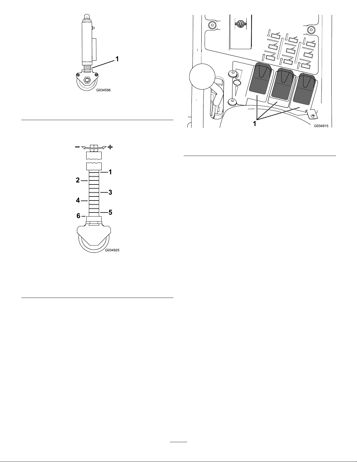
1.Indicatorrings
g034596
Figure31
Note:RefertoFigure32fortheheight-of-cut
settings.
Figure32
1.75mm(3.0inches)4.40mm(1.5inches)
2.65mm(2.5inches)5.25mm(1.0inches)
3.50mm(2.0inches)6.20mm(0.75inches)
g034915
Figure33
1.Lift-controlswitches
2.Toraisethecuttingunits,operatethelift-control
switchesinanupwarddirectionandholdin
position3.Ifthecutting-unit-driveswitchisin
theONpositiontheailrotordrivedisengages.
3.Releasethelift-controlswitcheswhenthecutting
unitsareattherequiredheight.
Note:Thecontrolswitchesautomatically
returntoposition2(NEUTRAL)andthearmsare
hydraulicallylockedintoposition.
Toraisethecuttingunitstothelimitedlift
position:momentarilyoperatetheswitchesinan
g034925
upwarddirection.
Theailrotordrivedisengagesimmediatelyandthe
cuttingunitsstopraising,approximately150mm(6
inches)abovegroundlevel.
Thisoperateswiththecuttingunitsloweredand
rotating.
ControllingthePositionof
theIndividualCuttingUnits
Thecuttingunitsmayberaisedorlowered
independentlyusingthebankof3lift-controlswitches.
1.Tolowerthecuttingunits,operatethelift-control
switchesinadownwarddirectionandrelease.
Note:Thecutting-unit-driveswitchmustbeon
todothis,theailrotordriveengageswhen
thecuttingunitsareapproximately150mm(6
inches)abovegroundlevel.Thecuttingunits
arenowin‘oat’modeandfollowtheground
contours.
Autolimitedliftinreversecausesthecuttingunits
toriseautomaticallytothelimitedliftpositionwhen
reversing.Theyreturntotheoatingpositionwhen
returningtoforwardtravel.Theailrotorscontinueto
rotateduringthisoperation.
UsingtheCuttingUnit
Auto-LimitedLiftinReverse
Toactivate,presstheauto-limited-liftswitchtotheON
position(Figure34).
Todeactivate,presstheauto-limited-liftswitchtothe
OFFposition(Figure34).
Manuallimitedliftusingthe3lift-controlswitchesis
alwaysavailableregardlessofthepositionoftheauto
switch.
26
thelift-controlswitch(s)inadownwarddirection.
Themachinedriveswhenthecuttingunitsare
approximately150mm(6inches)abovegroundlevel.
Using
Weight-Transfer/Traction
Assistance
Avariablehydraulicweighttransfersystemisprovided
forimprovingtiregripwiththegrasssurface—traction
assistance.
Hydraulicpressureinthecuttingunitsliftsystem
providesaliftingforcewhichreducestheweightofthe
cuttingunitsonthegroundandtransferstheweight
asadownwardforceontothetiresofthemachine.
Thisactionisknownasweighttransfer.
Toengageweighttransfer:Theamountofweight
transfercanbevariedtosuitoperatingconditionsby
rotatingtheweight-transferhandwheel(Figure36)
asfollows:
Figure34
EngagingtheCuttingUnit
Drive
Figure35
1.On2.Off
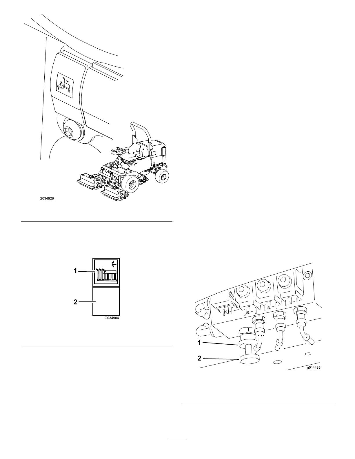
1.Releasethevalvelocknut1/2turn
counterclockwiseandhold(Figure36).
g034928
2.Rotatethevalvehandwheel(Figure36)
counterclockwisetoreduceweighttransferor
clockwisetoincreaseweighttransfer.
3.Tightenthenut.
Note:Therecommendedsettingistoincrease
weighttransferuntilheadsstarttolift,thenbackoff
1/2turn,andlock.
g034904
Thecuttingunitdrivecanbeengagedonlywhenthe
operatorisseatedcorrectly,refertoCheckingthe
Operator-Presence-SeatSwitch(page46).
Cuttingunitdriveengagement:Pressthetopofthe
cutting-unit-driveswitchtotheonposition(Figure35).
Allcuttingunitdrivesdisengagement:Setthe
switchtotheoffposition(Figure35).
Tolowerthecuttingunits:Thecuttingunitdrive
switchmustbesettotheonposition.Operate
g014435
Figure36
1.Lockwheel
27
2.Weight-transferhand
wheel

OperatingTips
drivingbetweenobjectssothatyoudonotaccidentally
damagethemachineorthecuttingunits.
BecomingFamiliarwiththe
Machine
Beforemowinggrass,practiceoperatingthemachine
inanopenarea.Startandshutofftheengine.
Operateinforwardandreverse.Lowerandraise
thecuttingunitsandengageanddisengagethe
cuttingunits.Whenyoufeelfamiliarwiththemachine,
practiceoperatingupanddownslopesatdifferent
speeds.
UnderstandingtheWarning
System
Ifawarninglightcomesonduringoperation,stopthe
machineimmediatelyandcorrecttheproblembefore
continuingoperation.Seriousdamagecouldoccurif
youoperatethemachinewithamalfunction.
MowingGrass
Therotationalspeedoftheailrotorsshouldalways
bekeptashighaspossibleinordertomaintainthe
highestqualityofcut.Thisinturnrequiresthatthe
enginespeedbekeptashighaspossible.
Cuttingperformanceisbestwhencuttingagainstthe
lieofthegrass.Inordertotakeadvantageofthisfact,
theoperatorshouldattempttoalternatethedirection
ofmowingbetweencuts.
Takecarenottoleaveuncutstripsofgrassatthe
overlappointsbetweenadjacentcuttingunitsby
avoidingtightturns.
WARNING
Takecarewhentravellingoverobstacles
suchasroadsidecurbsassuchobstacles
mayallowthemachinetorolloverwhichmay
causesevereinjury.
Alwaystravelatslowspeedoverobstacles
topreventdamagetothetires,wheels,and
steeringsystem.Ensurethatthetiresare
inatedtotherecommendedpressures.
OperatingtheMachineonSlopes
Useextracarewhenoperatingthemachineonslopes.
Driveslowlyandavoidsharpturnsonslopesto
preventrollovers.Lowerthecuttingunitsforsteering
controlwhengoingdownhill.
UsingtheRearRollerScrapers
Itisgenerallywisetoremoverearrollerscrapers
whereconditionsallow,asoptimumgrassdischarge
isachievedwithoutthem.Installthescraperswhen
conditionsaresuchthatmudandgrassstartto
buildupontherollers.Wheninstallingthescraper
wires,ensurethattheyarecorrectlytensioned.
AfterOperation
AfterOperationSafety
MaximizingtheQualityofCut
Thequalityofcutdeterioratesiftheforwardspeed
isexcessive.Alwaysbalancethequalityofcutwith
theworkraterequiredandsettheforwardspeed
accordingly.
MaximizingEngineEfciency
Donotlettheenginelabor.Ifyounoticethatthe
enginestartstolabor,reducetheforwardspeedor
increasetheheightofcut.Checktomakesurethat
theailbladesaresharp.
DrivingtheMachineinTransport
Mode
Alwaysdisengagethecuttingunitdrivewhen
travellingacrossun-grassedareas.Becarefulwhen
GeneralSafety
•Shutofftheengine,removethekey,andwait
forallmovementtostopbeforeyouleavethe
operator’sposition.Allowthemachinetocool
beforeadjusting,servicing,cleaning,orstoringit.
•Cleangrassanddebrisfromthecuttingunits,
drives,mufers,coolingscreens,andengine
compartmenttohelppreventres.Cleanupoilor
fuelspills.
•Shutoffthefuelwhilestoringorhaulingthe
machine.
•Disengagethedrivetotheattachmentwhenever
youarehaulingornotusingthemachine.
•Maintainandcleantheseatbelt(s)asnecessary.
•Donotstorethemachineorfuelcontainerwhere
thereisanopename,spark,orpilotlight,such
asonawaterheateroronotherappliances.
28

IdentifyingtheTie-Down
Points
Figure37
g014447
Figure38
1.Frontleftliftingpoint3.Rearliftingpoint
g282342
2.Frontrightliftingpoint
1.Fronttie-downpoint2.Reartie-downpoint
HaulingtheMachine
•Usefull-widthrampsforloadingthemachineonto
atrailerortruck.
•Tiethemachinedownsecurely.
LocatingtheJackingPoints
Note:Usejackstandstosupportthemachinewhen
required.
WARNING
Mechanicalorhydraulicjacksmayfailto
supportthemachineandcauseseriousinjury.
Usejackstandswhensupportingthe
machine.
TowingtheMachine
Ensurethatthetowingvehiclespecicationissuited
tobrakingthecombinedvehicleweightandableto
remainincompletecontrolatalltimes.Ensurethat
theparkingbrakeofthetowingvehicleisengaged.
Chockthefrontwheelsofthemachinetopreventthe
machinefromrollingaway.
Important:Donottowthemachinefasterthan
3to5km/h(2to3mph),otherwiseinternal
transmissiondamagemayoccur.
Decommissionthefrontwheelmotordiscbrakes
asfollows:
1.Connectarigidtowbarbetweenthetowingeye
onthefrontofthemowerandasuitabletowing
vehicle.
2.Identifytherightfrontwheelmotordiscbrake
assemblyandremovethehexplug(Figure39).
•Front—underthefrontarmmount
•Rear—axletubeontherearaxle
29

Figure39
1.Hexplug
3.LocatetheM12x40mmsetscrewandwasher
storedunderneaththeoperatorplatform,onein
eachoftheplatformsupportrails.
4.InstallaM12x40mmlongsetscrewwithwasher
intotheholeinthecenterofthemotorendplate
(Figure40).
heavyasthereisnohydraulicassistancewhen
theengineisshutoff.
g014448
g014450
Figure41
Figure40
1.Hexplug
2.WasherM12
3.SetscrewM12x40
5.Tightenthesetscrewintothethreadedhole
inthebrakepistonuntilthebrakeisreleased
(Figure40).
6.Identifytheleftfrontwheelmotordiscbrake
assemblyandrepeatthepreviousprocedure
(Figure40).
7.Decommissionthehydraulicservicebraking
systembyturningthebypassvalve,located
underthetransmissionpump,counterclockwise,
amaximumof3turns(Figure41).
1.Transmissionbypassvalves
8.Themowerisnowinafreewheelconditionand
canbetowedforashortdistanceatslowspeed.
Note:Removethewheelchocksbeforetowing.
9.Aftertowingthemower:T oreturnthemower
toitsnormalworkingconditionthefollowing
proceduremustbedone:
A.Chockthefrontwheels.
g014449
B.Closethebypassvalveonthetransmission
pumpbyturningitclockwise.
10.Commissionthefrontwheelmotordisc
brakesasfollows:
Note:EnsurethattheM12x40mm
setscrewsandwashersareremovedandstored
underneaththeoperatorplatform.
A.Identifytherightfrontwheelmotordisc
brakeassembly.
B.Rotatethesetscrewcounterclockwiseand
removetogetherwiththewasher.
C.Assemblethehexplugintothemotorend
plate(Figure42).
Thesteeringmustbeoperatedmanuallywhen
themowerisbeingtowed.Thesteeringwillfeel
30

Figure42
1.Frontwheelmoto3.WasherM12
2.Hexplug
4.SetscrewM12x40mm
D.Identifytheleftfrontwheelmotordisc
brakeassemblyandrepeattheprevious
procedure.
E.Removethewheelchocks.
F.Disconnectthetowbar.
Note:Themowerbrakingsystemwillnow
operateinthenormalway.
WARNING
Beforeusingthemower,ensurethatthe
brakingsystemoperatescorrectly.Carryout
initialcheckswiththemoweratslowspeed.
Donotoperatethemowerwithadamaged
brakingsystem.Donotoperatethemower
withthebrakesdecommissioned.
g014451
31

Maintenance
Note:Determinetheleftandrightsidesofthemachinefromthenormaloperatingposition.
MaintenanceSafety
•Beforeyouleavetheoperator’sposition,dothe
following:
–Parkthemachineonalevelsurface.
–Disengagethecuttingunit(s)andlowerthe
attachments.
–Engagetheparkingbrake.
–Shutofftheengineandremovethekey .
–Waitforallmovementtostop.
•Allowmachinecomponentstocoolbefore
performingmaintenance.
•Ifpossible,donotperformmaintenancewhilethe
engineisrunning.Keepawayfrommovingparts.
•Supportthemachinewithjackstandswhenever
youworkunderthemachine.
•Carefullyreleasepressurefromcomponentswith
storedenergy.
•Keepallpartsofthemachineingoodworking
conditionandallhardwaretightened.
•Replaceallwornordamageddecals.
•Toensuresafe,optimalperformanceofthe
machine,useonlygenuineT ororeplacement
parts.Replacementpartsmadebyother
manufacturerscouldbedangerous,andsuchuse
couldvoidtheproductwarranty .
32

RecommendedMaintenanceSchedule(s)
MaintenanceService
Interval
Aftertherst8hours
Aftertherst50hours
Beforeeachuseordaily
MaintenanceProcedure
•Checktheconditionandtensionofthealternatorbelt.
•Changetheengineoilandlter.
•Changethetransmission-oillter.
•Changethehydraulic-returnlter.
•Checktheenginespeed(idleandfullthrottle).
•Checkthehorn.
•Inspecttheseatbelt(s)forwear,cuts,andotherdamage.Replacetheseatbelt(s)if
anycomponentdoesnotoperateproperly.
•Checkthesafetyinterlocksystem.
•Checkthetirepressure.
•Greasethebearings,bushings,andpivots(greasethemimmediatelyafterevery
washingregardlessoftheintervallisted).
•Checktheair-cleaner-blockageindicator(servicetheaircleanerearlierifthe
air-cleanerindicatorshowsred;serviceitmorefrequentlyinextremelydirtyor
dustyconditions).
•Checktheengine-oillevel.
•Drainwaterorothercontaminantsfromthewaterseparator.
•Checkthetorquethewheel-lugnuts.
•Removedebrisfromthescreen,oilcoolers,andradiator(morefrequentlyindirty
operatingconditions).
•Checkthesafety-interlocksystem.
•Checkthehydrauliclinesandhoses.
•Checkthehydraulic-uidlevel.
•Checktheheight-of-cutsetting.
•Inspecttheailrotorsandbladesfordamage,cracks,andloosefasteners.Replace
anydamagedorcrackedparts.
•Checktherearguard.
•Checkthefrontrubberguard.
•Checkthecuttingunitpivot.
•Checkforanyunusualvibrationoftherotor.
•Checkthefastenersofthemachine.
•Checkthecuttingunits.
•Checktheforward/reversetravelpedalaction.
Every50hours
Every100hours
Every150hours
Every250hours
Every400hours
•Greasethebearings,bushings,andpivots(greasethemimmediatelyafterevery
washingregardlessoftheintervallisted).
•Checkthebladebolts.
•Inspectthebladesfordamageandexcessivewear.
•Makesurethateachbladeboltistorquedto45N∙m(33.2ft-lb).
•Checkthecuttingunitpivot.
•Checkforexcessiveplayintherotorbearings.
•Checktherear-rolleradjustment.
•Checktherear-rollerscraperwiretension.
•Inspectthecoolingsystemhoses.
•Checktheconditionandtensionofthealternatorbelt.
•Changetheengineoilandlter.
•Checktheconditionofthebattery.
•Checktheconditionofandcleanthebattery.
•Checkthebatterycableconnections.
•Checkthetransmission-controlcable.
•Checkthefuellinesandconnections.
•Checktheenginespeed(idleandfullthrottle).
33

MaintenanceService
Every500hours
Interval
MaintenanceProcedure
•Checktheengineoverheatwarningsystem.
•Replacetheprimaryairlter(morefrequentlyinextremedustyordirtyconditions).
•Replacethefuel-ltercanister.
•Checktheelectricalsystem.
•Changethetransmission-oillter.
•Changethehydraulic-returnlter.
•Checktherear-wheelalignment.
•Servicethehydraulicsystem.
•Checkthehydraulic-uid-overheatwarningsystem.
Every800hours
Beforestorage
Every2years
•Drainandcleanthefueltank.
•Adjusttheenginevalves(refertotheengineoperator’smanual).
•Drainandcleanthefueltank.
Yearly
•Replacetheblades.
•Flushandreplacethecoolingsystemuid.
•Replaceallmovinghoses.
•Replacethetransmissioncable.
34

DailyMaintenanceChecklist
Duplicatethispageforroutineuse.
Fortheweekof:
MaintenanceCheckItem
Checkthesafetyinterlockoperation.
Checkthebrakeoperation.
Checktheengineoilandfuellevel.
Checktheairlterrestrictionindicator.
Checktheradiatorandscreenfordebris.
Checkunusualenginenoises.
Checkunusualoperatingnoises.
Checkthehydraulicsystemoillevel.
Checkhydraulichosesfordamage.
Checkforuidleaks.
Checkthetyrepressure.
Checktheinstrumentoperation.
Checktherotorandblades.
Checktheheight-of-cutadjustment.
Checkallgreasettingsforlubrication.
Touch-updamagedpaint.
Washthemachine.
1.Checktheglowplugandinjectornozzlesifhardstarting,excesssmoke,orroughrunningisnoted.
1
2
Mon.Tues.Wed.Thurs.Fri.
Sat.Sun.
2.Immediatelyaftereverywashing,regardlessoftheintervallisted
NotationforAreasofConcern
Inspectionperformedby:
ItemDate
1
2
3
4
5
6
7
8
Important:Refertoyourengineoperator’smanualforadditionalmaintenanceprocedures.
Note:Downloadafreecopyoftheelectricalorhydraulicschematicbyvisitingwww.Toro.comandsearching
foryourmachinefromtheManualslinkonthehomepage.
Information
35

Lubrication
bearingsandbushingsimmediatelyafterevery
washing,regardlessoftheintervallisted.
GreasingtheBearings,
Bushings,andPivots
ServiceInterval:Beforeeachuseordaily
Every50hours
Lubricateallgreasettingsforthebearingsand
bushingswithNo.2lithiumgrease.Lubricatethe
Replaceanydamagedgreasettings.
Important:Use1pumpofgreaseonthe
height-of-cutadjustersand3pumpsofgreaseon
allothergreasettings.
Thegreasettinglocationsandquantitiesareas
follows:
Figure43
1.–Greaseevery50hours2.–Greasedaily
EngineMaintenance
CheckingtheEngine
OverheatWarningSystem
EngineSafety
•Shutofftheenginebeforecheckingtheoilor
addingoiltothecrankcase.
•Donotchangethegovernorspeedoroverspeed
theengine.
ServiceInterval:Every500hours
36
g034909

Figure45
g014565
Figure44
1.Temperatureswitch
1.TurntheignitionkeytotheignitiononpositionI.
2.Disconnectthered/bluewireterminalfromthe
engine-temperatureswitch.
3.Touchthemetalterminalofthiswireontoa
suitableearthpoint,ensuringthatthemetal
surfacesmakegoodcontact.
Thehornsoundsandthe
engine-coolant-temperature-warninglightilluminates
toconrmcorrectoperation.Ifthesystemis
malfunctioning,makerepairsbeforeoperatingthe
mower.
ServicingtheAirCleaner
ServiceInterval:Beforeeachuseordaily
Every500hours
ServicingthePrimaryAirFilter
g014437
2.Beforeremovingthelter,uselowpressure
air(40psi,cleananddry)tohelpremove
largeaccumulationsofdebrispackedbetween
outsideofthelterandthecanister.Avoid
usinghigh-pressureairwhichcouldforce
dirtthroughthelterintotheintaketract.
Note:Thiscleaningprocesspreventsdebris
frommigratingintotheintakewhenthelteris
removed.
g022394
Figure46
1.Rubberoutletvalve
2.Removablecover
3.Airlter
Checktheair-cleanerbodyfordamagewhichcould
causeanairleak.Replaceifdamaged.Checkthe
wholeintakesystemforleaks,damageorloosehose
clamps.
Servicetheprimaryair-cleanerlteronlywhenthe
serviceindicator(Figure45)requiresit.Changing
theairlterbeforeitisnecessaryonlyincreasesthe
chanceofdirtenteringtheenginewhenthelteris
removed.
Important:Besurethatthecoverisseated
correctlyandsealswiththeair-cleanerbody.
1.Checkthelter-blockageindicator.Ifthe
indicatorisred,theairlterneedstobecleaned
orreplaced(Figure45).
3.Removethecoverfromtheair-cleanerbody .
4.Removeandreplacethelter(Figure46).
Cleaningoftheusedelementisnot
recommendedduetothepossibilityofdamage
totheltermedia.
5.Inspectthenewlterforshippingdamage,
checkingthesealingendofthelterandthe
body.Donotuseadamagedelement.
6.Insertthenewlterbyapplyingpressuretothe
outerrimoftheelementtoseatitinthecanister.
Donotapplypressuretotheexiblecenter
ofthelter.
7.Cleanthedirtejectionportlocatedinthe
removablecover.Removetherubberoutlet
valvefromthecover,cleanthecavityand
replacetheoutletvalve.
37

8.Installthecoverorientingtherubberoutletvalve
inadownwardposition—betweenapproximately
5o’clockto7o’clockwhenviewedfromtheend.
9.Checktheconditionoftheair-cleanerhoses.
10.Securethecover.
ServicingtheSafetyFilter
Theairlterhasasecondary ,safetylterelement
insidetheprimaryairltertopreventdislodged
dustandotheritemsfromenteringtheenginewhile
changingthemainelement.
Replacethesafetylter,nevercleanit.
Important:Neverattempttocleanthesafety
lter.Ifthesafetylterisdirty,thentheprimary
lterisdamaged.Replacebothlters.
CheckingtheEngine-Oil
Level
ServiceInterval:Beforeeachuseordaily
Theengineisshippedwithoilinthecrankcase;
however,theoillevelmustbecheckedbeforeand
aftertheengineisrststarted.
g008881
Figure47
1.Dipstick
4.Removedipstickandcheckoillevelondipstick.
Note:TheoillevelshouldbeuptotheFULL
mark.
5.IftheoillevelisbelowtheFULLmark,remove
thellcap(Figure48)andaddoiluntillevel
reachestheFULLmarkondipstick.
Important:Donotoverll.
Crankcasecapacity:approximately6.7L(7.1US
qt)withthelter
Usehigh-qualityengineoilthatmeetsthefollowing
specications:
•APIClassicationLevelRequired:CH-4,CI-4or
higher
•Preferredoil:SAE15W-40(above0°F)
•Alternateoil:SAE10W-30or5W-30(all
temperatures)
ToroPremiumEngineoilisavailablefromyour
distributorineither15W-40or10W-30viscosity.
Note:Thebesttimetochecktheengineoiliswhen
theengineiscoolbeforeithasbeenstartedforthe
day.Ifithasalreadybeenrun,allowtheoiltodrain
backdowntothesumpforatleast10minutesbefore
checking.
1.Parkthemachineonalevelsurface,lowerthe
cuttingunits,engagetheparkingbrake,shutoff
theengine,andremovethekey.
2.Openthehood.
g004134
Figure48
1.Oil-llcap
6.Installtheoil-llcapandclosethehood.
ServicingtheEngineOil
3.Removethedipstick,wipeitclean,andinstallit
(Figure47).
andFilter
ServiceInterval:Aftertherst50hours
Every150hours
38
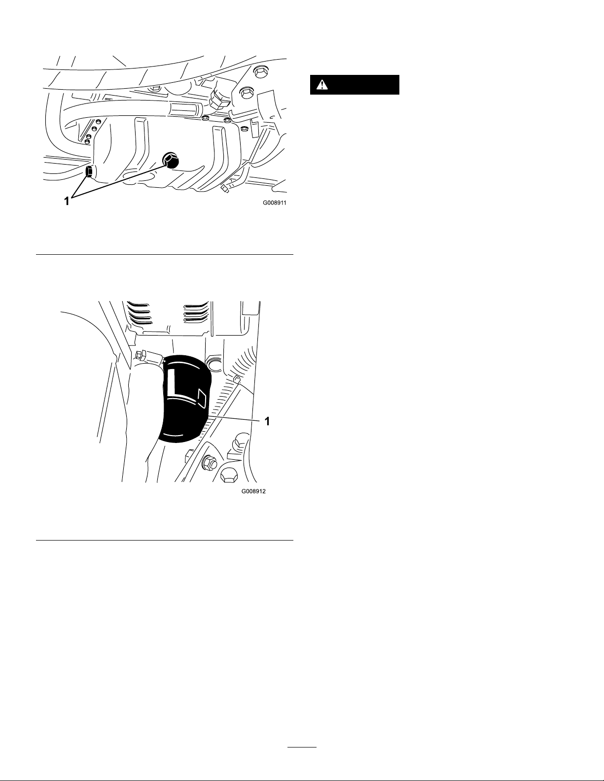
1.Removethedrainplug(Figure49)andletthe
oilowintoadrainpan.
Figure49
1.Oil-drainplug
2.Whentheoilstops,installthedrainplug.
3.Removetheoillter(Figure50).
g008911
FuelSystem
Maintenance
DANGER
Undercertainconditions,fuelandfuelvapors
arehighlyammableandexplosive.Areor
explosionfromfuelcanburnyouandothers
andcancausepropertydamage.
•Fillthefueltankoutdoors,inanopenarea,
whentheengineisoffandiscold.Wipeup
anyfuelthatspills.
•Donotllthefueltankcompletelyfull.Add
fueltothefueltankuntilthelevelis25mm
(1inch)belowthetopofthetank,notthe
llerneck.Thisemptyspaceinthetank
allowsthefueltoexpand.
•Neversmokewhenhandlingfuel,andstay
awayfromanopenameorwherefuel
fumesmaybeignitedbyaspark.
•Storefuelinaclean,safety-approved
containerandkeepthecapinplace.
Figure50
1.Oillter
4.Applyalightcoatofcleanoiltothenewlter
seal.
5.Installthereplacementoilltertothelter
adapter.Turntheoillterclockwiseuntilthe
rubbergasketcontactsthelteradapter,then
tightenthelteranadditional1/2turn.
Important:Donotovertightenthelter.
6.Addoiltothecrankcase;refertoCheckingthe
Engine-OilLevel(page38).
DrainingtheFuelTank
ServiceInterval:Every800hours
Beforestorage
Drainandcleanthefueltankifthefuelsystem
becomescontaminatedorifthemachineistobe
storedforanextendedperiod.Usecleanfueltoush
outthetank.
CheckingtheFuelLines
g008912
andConnections
ServiceInterval:Every400hours/Y early(whichever
comesrst)
Checkthefuellinesandconnections.Inspectthem
fordeterioration,damage,orlooseconnections.
BleedingtheFuelSystem
Youmustbleedthefuelsystembeforestartingthe
engineifanyofthefollowingsituationshaveoccurred:
•Initialstart-upofanewmachine.
•Enginehasceasedrunningduetolackoffuel.
•Maintenancehasbeenperformeduponfuel
systemcomponents;i.e.,lterreplaced,separator
serviced,etc.
1.Parkthemachineonalevelsurfaceandensure
thatthefueltankisatleasthalffull.
39

2.Openthehood.
3.TurnthekeyintheignitionswitchtotheON
positionandcranktheengine.
Note:Themechanicalpumpsucksfueloutof
thetank,llthefuellterandfuelhoseandforce
theairintotheengine.Thiscouldtakesome
timetofullypurgealltheairoutofthesystem
andtheenginemightreerraticallyuntilallair
ispurgedout.Whenallairispurgedandthe
engineisrunningsmoothly,itshouldberunfor
afewminutestoensurethatitisfullypurged.
ReplacingtheFuelFilter
ServiceInterval:Every500hours
Beforeeachuseordaily—Drainwaterorother
contaminantsfromthewaterseparator.
Important:Replacethefuel-ltercanister
periodicallytopreventwearofthe
fuel-injection-pumpplungerortheinjection
nozzle,duetodirtinthefuel.
1.Placeacleancontainerunderthefuel-lter
canister(Figure51).
Note:Thefuel-ltercanisterislocatednearthe
batteryundertheenginecover.
2.Loosenthedrainplugonthebottomofthelter
canister.
3.Cleantheareawheretheltercanistermounts.
Figure51
1.Fuel-ltercanister
4.Removetheltercanisterandcleanthe
mountingsurface.
5.Lubricatethegasketontheltercanisterwith
cleanoil.
6.Installthenewltercanisterbyhanduntilthe
gasketcontactsmountingsurfaceandthen
rotateitanadditional1/2turn.
7.Tightenthedrainplugonthebottomofthelter
canister.
8.Bleedthefuelsystem;refertoBleedingtheFuel
System(page39).
g007367
40

ElectricalSystem
ServicingtheBattery
Maintenance
ElectricalSystemSafety
•Disconnectthebatterybeforerepairingthe
machine.Disconnectthenegativeterminalrst
andthepositivelast.Connectthepositiveterminal
rstandthenegativelast.
•Chargethebatteryinanopen,well-ventilated
area,awayfromsparksandames.Unplugthe
chargerbeforeconnectingordisconnectingthe
battery.Wearprotectiveclothinganduseinsulated
tools.
CheckingtheElectrical
System
ServiceInterval:Every500hours
Inspectallelectricalconnectionsandcablesand
replaceanywhicharedamagedorcorroded.Spraya
good-qualitywaterinhibitorontoexposedconnections
topreventmoistureingress.
CheckingtheBattery
Condition
ServiceInterval:Every250hours
DANGER
Batteryelectrolytecontainssulfuricacid
whichisadeadlypoisonandcausessevere
burns.
•Donotdrinkelectrolyteandavoidcontact
withskin,eyes,orclothing.Weareye
protectiontoshieldyoureyesandrubber
glovestoprotectyourhands.
•Fillthebatterywherecleanwaterisalways
availableforushingtheskin.
WARNING
Chargingthebatteryproducesgassesthat
canexplode.
Neversmokenearthebatteryandkeepsparks
andamesawayfromit.
Checkthebatterycondition.Keeptheterminalsand
theentirebatterycasecleanbecauseadirtybattery
dischargesslowly.T ocleanthebattery,washthe
entirecasewithasolutionofbakingsodaandwater.
Rinseitwithclearwater.
ServiceInterval:Every250hours
Note:Whenremovingthebattery,alwaysdisconnect
thenegative(-)cablerst.
Note:Wheninstallingthebattery,alwaysconnect
thenegative(-)cablelast.
Raisetheenginecover.Removeanycorrosionfrom
thebatteryterminalsusingawirebrushandapply
petroleumjellytotheterminalstopreventfurther
corrosion.Cleanthebatterycompartment.
Undernormaloperatingconditionsthebatterydoes
notrequireanyfurtherattention.Ifthemachinehas
beensubjecttocontinuoususeunderhighambient
temperatureconditions,thebatteryelectrolytemay
requiretoppingup.
Removethecellcoversandtopupwithdistilledwater
toaheight15mmbelowthetopofthebattery.Install
thecellcovers.
Note:Checktheconditionofthebatterycables.
Installnewcableswhencurrentonesareshowing
signsofwearordamageandtightenanyloose
connectionsasnecessary.
41

DriveSystem
ChangingtheTransmission
Maintenance
CheckingtheTirePressure
Checktheairpressureinthefrontandreartires.
Refertothechartbelowforthecorrectpressure.
Important:Maintaincorrecttirepressureinall
tirestoensurecorrectcontactwiththeturf.
Recommendedtirepressureis1bar(14.5psi)
forgeneralallarounduse.Tirepressurescanbe
adjustedaccordingtothefollowingtabledepending
onoperatingconditions.
RecommendedTirePressures TiresTireType
Turf
Conditions
FrontAxle26x
12.0-12
BKTturf
pattern
RearAxle20x10.0-
8BKTturf
pattern
0.7bar(10
psi)
0.7bar(10
psi)
CheckingtheTorqueofthe
Wheel-LugNuts
Conditions
1.4bar(20
1.4bar(20
Road
1.7bar(25
psi)
1.7bar(25
psi)
OilFilter
ServiceInterval:Aftertherst50hours
Every500hours
Maximum
Pressure
psi)
psi)
g018091
Figure52
RightSideofMachine
1.Transmission-oillter
ServiceInterval:Beforeeachuseordaily
Torquethewheel-lugnutsto200N∙m(148ft-lb)for
thefrontaxle,and54N∙m(40ft-lb)fortherearaxle.
WARNING
Failuretomaintainpropertorqueofthewheel
nutscouldresultinpersonalinjury.
Ensurethatthewheelnutsaretorqued
properly.
1.Unscrewandremovethebottomofthe
transmission-oil-lterhousing.
2.Withdrawthelterelementanddiscardit.
3.Installanewlterelement.
4.Installthehousing.
Changingthe
Hydraulic-ReturnFilter
ServiceInterval:Aftertherst50hours
Every500hours
1.Removethereturnlter.
2.Wipeoilontothenewreturnltergasket.
3.Installthenewreturnltertothemachine.
42

LeftSideofMachine
Figure53
assembly.(Leftlocknuthasaleftthread).Rotatethe
trackrodtoachievethecorrectdistanceasdescribed
aboveandtightenthelocknutssecurely .
Inspectingthe
TransmissionControl
CableandOperating
Mechanism
ServiceInterval:Every250hours
Checktheconditionandsecurityofthecableand
operatingmechanismatthespeed-controlpedalsand
transmissionpumpends.
•Removebuildupofdirt,gritandotherdeposits.
g014491
•Ensurethattheballjointsaresecurelyanchored
andcheckthatthemountingbracketsandcable
anchorsaretightandfreefromcracks.
1.Hydraulic-uid-returnlter
CheckingtheRear-Wheel
Alignment
ServiceInterval:Every500hours
Topreventexcessivetirewearandensuresafe
machineoperation,therearwheelsmustbecorrectly
alignedto3to8mm(0.12to0.31inch).
Settherearwheelsinthestraightaheadposition.
Measureandcomparethedistancebetweenthefront
sidewallsandtherearsidewallsatthewheelcenter
height.Thedistancebetweenthefrontsidewallsmust
beset3to8mm(0.12to0.31inch)lessthanthe
distancebetweentherearsidewalls.
•Inspectendttingsforwear,corrosion,broken
springs,andreplaceifnecessary .
•Ensurethattherubbersealsarecorrectlylocated
andareingoodcondition.
•Ensurethatthearticulatingsleevessupporting
theinnercableareingoodconditionandrmly
attachedtotheoutercableassemblyatthe
crimpedconnections.Ifthereareanysigns
ofcrackingordetachmentinstallanewcable
immediately.
•Checkthatsleeves,rods,andinnercablearefree
frombends,kinks,orotherdamage.Iftheyare
not,installanewcableimmediately.
•Withtheengineshutoff,operatethepedal
controlsthroughtheentirerangeandensurethat
themechanismmovessmoothlyandfreelytothe
neutralpositionwithoutstickingorhangingup.
Figure54
1.Wheelcenterheight
2.Tire4.Track-rodassembly
Toadjustthealignmentoftherearwheels,rst
backofftheleftandrightlocknutsonthetrackrod
3.Directionofforwardtravel
g014571
Figure55
g014442
1.Outercover3.Sleeve
2.Rubberseal4.Rodend
43

CoolingSystem
Maintenance
CoolingSystemSafety
•Swallowingenginecoolantcancausepoisoning;
keepoutofreachfromchildrenandpets.
•Dischargeofhot,pressurizedcoolantortouching
ahotradiatorandsurroundingpartscancause
severeburns.
–Alwaysallowtheenginetocoolatleast15
minutesbeforeremovingtheradiatorcap.
–Usearagwhenopeningtheradiatorcap,and
openthecapslowlytoallowsteamtoescape.
RemovingDebrisfromthe
CoolingSystem
g004138
Figure56
1.Rearscreenlatch2.Rearscreen
ServiceInterval:Beforeeachuseordaily
Every100hours
Every2years
Note:Topreventtheenginefromoverheating,the
radiatorandoilcoolermustbekeptclean.Normally ,
checkdailyand,ifnecessary,cleananydebrisoff
theseparts.However,itisnecessarytocheckand
cleanmorefrequentlyinextremelydustyanddirty
conditions.
1.Turntheengineoffandremovethekeyfromthe
ignitionswitch.
2.Thoroughlycleanalldebrisoutoftheengine
area.
3.Unlatchtheclampandpivotopentherear
screen(Figure56).
4.Cleanthescreenthoroughlywithcompressed
air.
5.Pivotthelatchesinwardtoreleasetheoilcooler
(Figure57).
g003974
Figure57
1.Oilcooler2.Oilcoolerlatches
6.Thoroughlycleanbothsidesoftheoilcoolerand
theradiator(Figure58)withcompressedair.
44
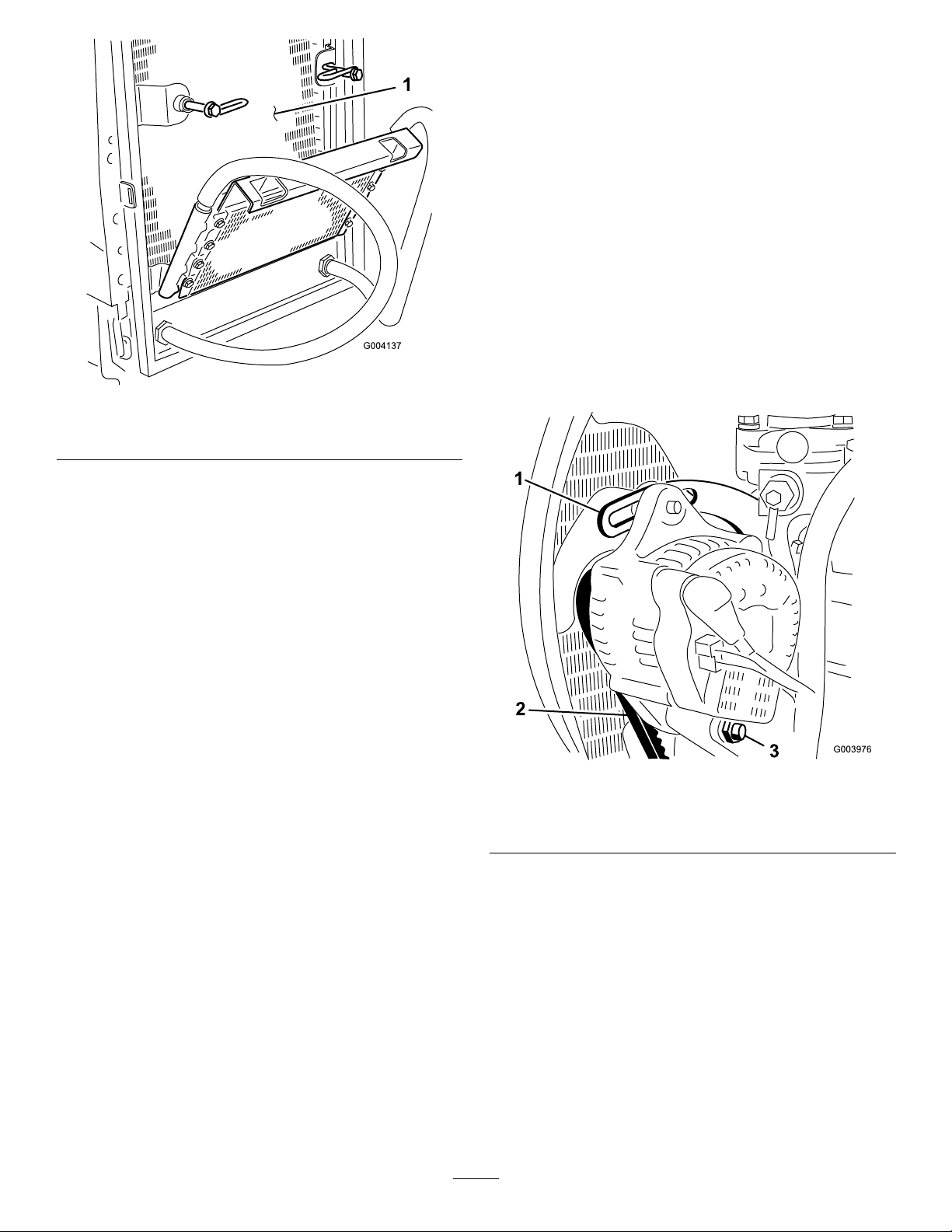
Figure58
1.Radiator
7.Pivottheoilcoolerbackintopositionandsecure
thelatches.
BeltMaintenance
TensioningtheAlternator
Belt
ServiceInterval:Aftertherst8hours
Every100hours
1.Openthehood.
2.Checkthetensionofthealternatorbeltby
pressingit(Figure59)midwaybetweenthe
alternatorandthecrankshaftpulleyswith10kg
(22lb)offorce.
Note:Thebeltshoulddeect11mm(7/16
inch).Ifthedeectionisincorrect,proceedto
g004137
step3.Ifcorrect,continueoperation.
8.Closethescreenandsecurethelatch.
g003976
Figure59
1.Brace3.Pivotbolt
2.Alternatorbelt
3.Loosentheboltsecuringthebracetotheengine
(Figure59),theboltsecuringthealternatorto
thebraceandthepivotbolt.
4.Insertaprybarbetweenthealternatorandthe
engineandpryoutonthealternator.
5.Whenyouachievethepropertension,tighten
thealternator,brace,andpivotboltstosecure
theadjustment.
45

ControlsSystem
Checkingthe
Maintenance
Checkingthe
Forward/ReverseTravel
PedalAction
Withtheengineshutoff,operatetheforwardand
reversetravelpedalsthroughthefullrangeof
articulationandensurethatthemechanismreturns
freelytotheNEUTRALposition.
Checkingthe
Operator-Presence-Seat
Switch
ServiceInterval:Beforeeachuseordaily
1.Sitontheoperatorseatandstarttheengine.
2.Lowerthecuttingunitstotheground.
3.Engagethecutterdrive.
4.Risefromtheoperatorseatandcheckthatthe
ailrotorscometoastopafteraninitial0.5to1
seconddelay.
Checkingthe
Parking-Brake-Interlock
Switch
1.Shutofftheengine.
2.Engagetheparkingbrake.
3.TurntheignitionkeytopositionI.Theparking
brakeindicatorlightshouldilluminate.
4.Disengagetheparkingbrake.Theindicatorlight
shouldgooutandtheengineshouldnotstart
whentheignitionkeyisturned.
5.Settheparkingbrake,sitontheoperatorseat,
andstarttheengine.
6.Releasetheparkingbrake.
7.Risefromtheoperatorseatandcheckthatthe
engineshutsoff.
Checkingthe
Transmission-Neutral-Interlock
Switch
1.Shutofftheengine.
2.Removeyourfootfromtheforward/reverse
travelpedals.
3.TurntheignitionkeytopositionIandthe
transmissionneutralindicatorlightshould
illuminate.
Cutter-Drive-Interlock
Switch
1.Shutofftheengine.
2.Turnthecutter-driveswitchtotheOFFposition
andturntheignitionkeytopositionI.Thecutting
unitsdriveswitchindicatorlightshouldnot
illuminate.
3.Turntheswitchtotheonposition.Theindicator
lightshouldilluminateandtheengineshouldnot
startwhentheignitionkeyisturned.
4.Applylightpressuretothetravelpedalsina
forwardandreversedirectiontocheckthatthe
indicatorlightturnsoff.
Note:Takeextremecaretoensurethatthearea
aroundthemowerisclearbeforecheckingtoseeif
theenginestartsunderthiscondition.
46

HydraulicSystem
Maintenance
HydraulicSystemSafety
•Seekimmediatemedicalattentionifuidisinjected
intoskin.Injecteduidmustbesurgicallyremoved
withinafewhoursbyadoctor.
•Ensurethatallhydraulic-uidhosesandlinesare
ingoodconditionandallhydraulicconnections
andttingsaretightbeforeapplyingpressureto
thehydraulicsystem.
•Keepyourbodyandhandsawayfrompinhole
leaksornozzlesthatejecthigh-pressurehydraulic
uid.
•Usecardboardorpapertondhydraulicleaks.
•Safelyrelieveallpressureinthehydraulicsystem
beforeperforminganyworkonthehydraulic
system.
CheckingtheHydraulic
LinesandHoses
ServiceInterval:Beforeeachuseordaily
Checkthehydrauliclinesandhosesforleaks,kinked
lines,loosemountingsupports,wear,loosettings,
weatherdeterioration,andchemicaldeterioration.
Makeallnecessaryrepairsbeforeoperating.
onlyproductsfromreputablemanufacturerswho
standbehindtheirrecommendation.
HighViscosityIndex/LowPourPointAntiwearHydraulic
Fluid,ISOVG46Multigrade
MaterialProperties:
Viscosity,ASTMD445cSt@40°C(104°F)
Viscosityindex,ASTM
D2270
Pourpoint,ASTMD97-36.7°Cto-45°C(-34°Fto
FZG,failstage
Watercontent(newuid)500ppm(maximum)
IndustrySpecications:
VickersI-286-S,VickersM-2950-S,DenisonHF-0,
Vickers35VQ25(EatonATS373-C)
Theproperhydraulicuidsmustbespeciedfor
mobilemachinery(asopposedtoindustrialplant
usage),multiweight-type,withZnDTPorZDDP
antiwearadditivepackage(notanashless-typeuid).
44to48
cSt@100°C(212°F)
7.9to9.1
140orhigher(high
viscosityindexindicatesa
multiweightuid)
-49°F)
11orbetter
Important:Manyhydraulicuidsarealmost
colorless,makingitdifculttospotleaks.A
reddyeadditiveforthehydraulicsystemoilis
availablein20ml(2/3oz)bottles.Onebottle
issufcientfor15to22L(4to6USgallons)of
hydraulicuid.Orderpart44-2500fromyour
authorizedTorodistributor.
Synthetic,BiodegradableHydraulicFluid:
Availablein19L(5USgallon)containersor208
L(55USgallon)drums—contactyourauthorized
Torodistributorforpartnumbers.
CheckingtheHydraulic
Fluid
ServiceInterval:Beforeeachuseordaily
Thereservoirislledatthefactorywithapproximately
32L(8.5USgallons)ofhigh-qualityhydraulicuid.
Thebesttimetocheckthehydraulicuidiswhen
itiscold.
Therecommendedreplacementuidis:
ToroPremiumAllSeasonHydraulicFluid:
Availablein19L(5USgallon)containersor208L
(55USgallon)drums—contactyourauthorizedToro
distributorforpartnumbers.
Alternativeuids:IftheT orouidisnotavailable,
otheruidsmaybeusedprovidedthattheymeet
allofthefollowingmaterialpropertiesandindustry
specications.Checkwithyouroilsuppliertoidentify
asatisfactoryproduct.
Note:T orodoesnotassumeresponsibilityfor
damagecausedbyimpropersubstitutions,souse
Thishigh-quality,synthetic,biodegradableuidhas
beentestedandfoundcompatibleforthisT oro
model.Otherbrandsofsyntheticuidmayhave
sealcompatibilityproblemsandTorocannotassume
responsibilityforunauthorizedsubstitutions.
Note:Thissyntheticuidisnotcompatiblewiththe
ToroBiodegradableFluidpreviouslysold.Seeyour
ToroDistributorformoreinformation.
Alternativeuids:
•MobilEALEnvirosynH46(US)
•MobilEALHydraulicOil46(international)
1.Parkthemachineonalevelsurface,lowerthe
cuttingunits,engagetheparkingbrake,shutoff
theengine,andremovethekey.
2.Checkthesight-levelgaugeonthesideofthe
tank.
Note:Thelevelneedstobeattheuppermark.
3.Ifadditionalhydraulicuidisneeded,cleanthe
areaaroundthellerneckandthecapofthe
hydraulictank(Figure60)andremovethecap.
47

Figure60
g014570
1.Hydraulic-tankcap
2.Fluidtank
3.Sight-levelgauge
4.Removethecapandllthetanktotheupper
markonthesight-levelgauge.
Important:Donotoverllthetank.
5.Installthecapontothetank.
ServicingtheHydraulic
System
ServiceInterval:Every500hours
Note:Keepwaterawayfromelectricalcomponents.
Useadryclothorbrushtocleansuchareas.
Thisprocedureisbestcarriedoutwhenthehydraulic
uidiswarm(nothot).Lowerthecuttingunitstothe
groundanddrainthehydraulicsystem.
1.Removethehydraulictankdrainplugandletthe
oilowintothedrainpain.
1.Oil-tankllercap
2.Suctionstrainer
Checkingthe
Hydraulic-Fluid-Overheat
WarningSystem
ServiceInterval:Every500hours
g014452
Figure61
3.Fillerstrainer
2.Whentheoilstops,installthedrainplugwitha
newseal.
3.Removetheoiltanksuctionangetogain
accesstothesuctionstrainer.
4.Unscrewandremovethestrainerandcleanwith
parafnorpetrolbeforeinstalling.
5.Installthereturnlineoillterelement.
6.Installthetransmissionoillterelement.
7.Fillthehydraulictankwithfresh,cleanhydraulic
uidoftherecommendedgrade.
8.Runthemachineandoperateallhydraulic
systemsuntilthehydraulicuidiswarm.
9.Checktheuidlevelandtopupasnecessaryto
theuppermarkonthesight-levelgauge.
Figure62
1.Temperatureswitch
1.TurntheignitionkeytotheignitiononpositionI.
2.Disconnectthered/yellowwireterminalfromthe
hydraulic-tank-temperatureswitch.
3.Touchthemetalterminalofthewireontoa
suitableearthpoint,ensuringthatthemetal
surfacesmakegoodcontact.
Thehornsoundsandthe
hydraulic-uid-temperature-warninglightilluminates
toconrmcorrectoperation.Ifnecessary,make
repairsbeforeoperatingthemower.
48
2.Hydraulic-uidtank
g022285
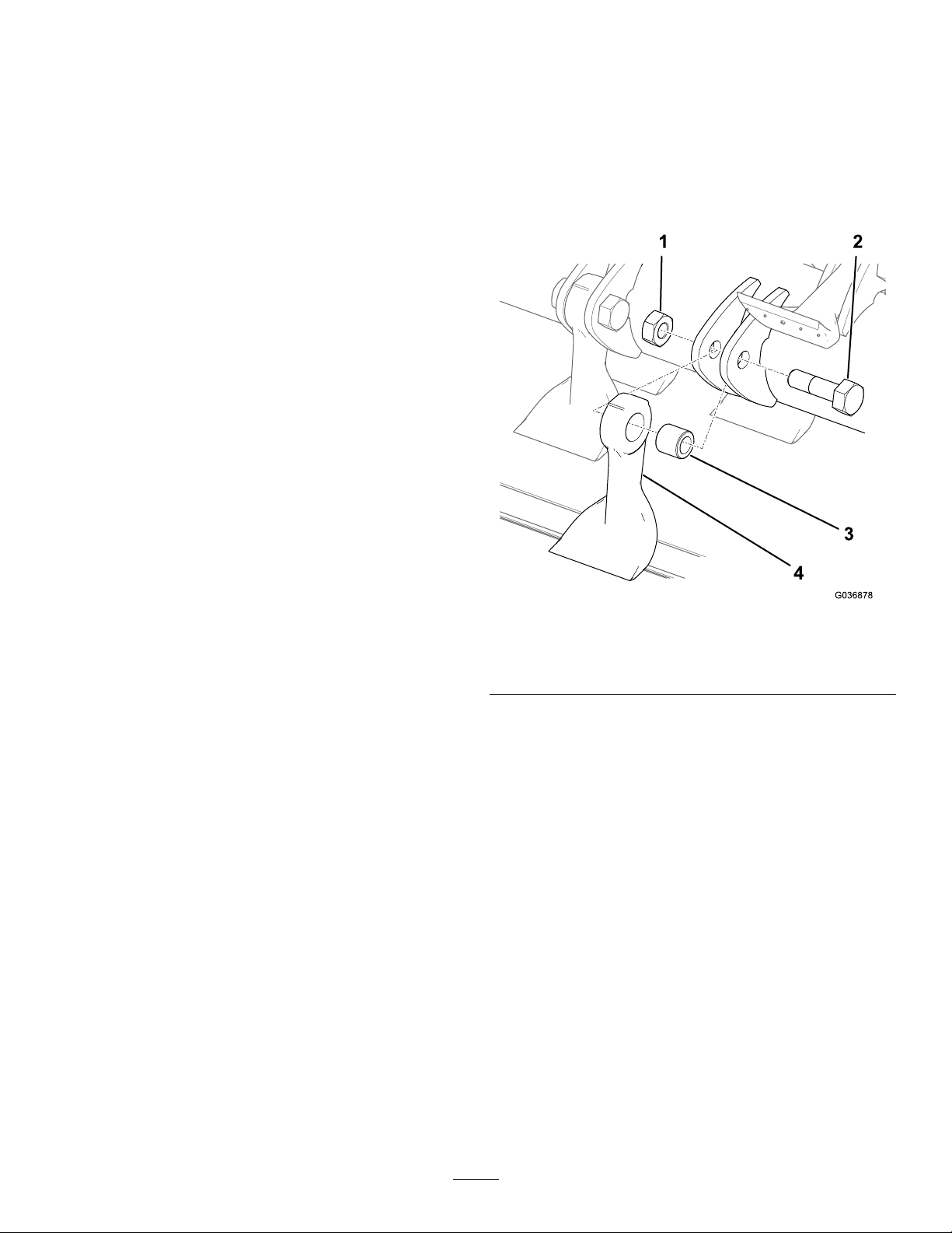
CuttingUnitMaintenance
BladeSafety
•Inspectthebladeperiodicallyforwearordamage.
•Usecarewhencheckingtheblades.Wrapthebladesorweargloves,andusecautionwhenservicingthe
blades.Onlyreplaceorsharpentheblades;neverstraightenorweldthem.
•Onmulti-bladedmachines,takecareasrotating1bladecancauseotherbladestorotate.
ReplacingtheBlades
ServiceInterval:Yearly—Replacetheblades.
Tomaintainbalance,replacebladesonlyasan
opposedpairorawholerotoratatime.Alsoreplace
thebushing,thebolt,andthelocknutwhenyou
replaceablade.Thereare2servicekitsavailablefor
bladereplacement;refertothePartsCatalog.
1.Raisethecuttingunitsandsecurethemwiththe
transportlatches.
2.Engagetheparkingbrake,shutofftheengine,
andremovethekey.
3.Ifyouarereplacingbladesonthecentercutting
unit,removetheentirecuttingunitunlessan
overheadliftisavailable.
4.Turntherotorslowlybyhandsothateachrow
ofailsareinthedesiredpositionandyoucan
easilyaccessthem.
5.Usetherotorlockingtool(providedinthe
blade-sharpeningkit)tolocktherotor.
6.Removeanydebrisfromtheboltheadandthe
nutandcleantheprotrudingthreadswithawire
brush.
7.Markthepositionoftheboltheadsothatyou
canreplacetheboltsfromthesameside.
8.Holdingthebladeinaragorpaddedglove,
removethenut,bolt,bushing,andblade(Figure
63).
Note:Ifneeded,applypenetratingoiltothe
threadstomakethenuteasiertoremove.
g036878
Figure63
1.Nut3.Bushing
2.Bolt4.Blade
9.Discardtheblade,bushing,nut,andbolt.
10.Installanewbladeandbushingwithanewnut
andbladebolt(Figure63).
Note:Payattentiontothebolt-head-position
markingssothatyoureplacetheboltinthe
samedirection.
11.T orquethefastenersto45N∙m(33ft-lb).
CheckingtheBladeBolts
ServiceInterval:Every50hours
Makesurethatallbladeboltsaretorquedto45N∙m
(33ft-lb).
InspectingtheBlades
ServiceInterval:Every50hours—Inspecttheblades
fordamageandexcessivewear.
Every50hours—Makesurethateachblade
boltistorquedto45N∙m(33.2ft-lb).
49

Important:Bladesshouldalwaysbereplacedat
thesametimeastheoppositeblade/aspairsto
maintainbalance.
1.Parkthemachineonalevelsurface.
2.Raiseandsupportthecuttingunitwiththe
transportlatches.
3.Shutofftheengine,engagetheparkingbrake,
andremovethekey.
4.Inspecteachbladefordamagepayingparticular
attentiontothefasteners,cuttingedge,and
installationhole(Figure64).Replaceall
damagedbladesandfasteners.
Note:Eachpairofoppositebladesshouldnot
haveaweightdifferenceofmorethan10grams.
DANGER
Awornordamagedbladecanbreak,anda
pieceofthebladecouldbethrowntowardyou
orbystanders,resultinginseriouspersonal
injuryordeath.
•Inspectthebladesperiodicallyforwearor
damage.
•Replaceawornordamagedblade.
CheckingtheRearGuard
ServiceInterval:Beforeeachuseordaily
Inspecttherearguardforwearordamage(Figure
66).Replacetherearguardifitisdamagedtoprevent
objectsbeingthrownintotheoperator’sarea.
Figure64
1.Cuttingedge
5.Inspecteachbladeforexcessivewearusingthe
wearline(Figure65).Whenabladeisworn
downtothewearline,replacetheblade.
1.Wearline
6.Makesurethateachbladeboltistorquedto45
N∙m(33.2ft-lb).
7.Gripeachbladeandmakesurethatthereis
notmorethanatotalof3mm(1/8inch)offree
movementineitherdirectionfromtherotor.If
thereismorethanatotalof3mm(1/8inch)of
freemovement,replacetheblade.
8.Checkeachpairofoppositebladesforaweight
differencebetweenthem.
2.Installationhole
Figure65
g034632
g034664
Figure66
1.Rearguard
ClearingaBlockedRotor
g034634
WARNING
Residualpressureinthehydraulicsystem
couldcauseinjurythroughsuddenmovement
oftheailrotor(s)whentheblockageis
released.
•Neverattempttorotateorclearblockage
fromtheailrotorsbyhand.
•Alwayswearprotectiveglovesandusea
woodenpole.
•Ensurethatthewoodenpolewilltinthe
ailrotorandislongenoughtoprovide
sufcientleveragetoreleasetheblockage.
50

1.Setthecutting-unit-driveswitchtotheOFF
position.
2.Parkthemachineonlevelground,releasethe
forwardorreversetravelpedals,setthethrottle
controltotheslowengine-speedposition,and
engagetheparkingbrake.
CheckingtheRotor
ServiceInterval:Beforeeachuseordaily—Checkfor
anyunusualvibrationoftherotor.
Every50hours—Checkforexcessiveplayin
therotorbearings.
3.Lowerthecuttingunitstothegroundorsecurely
locktheminthedesignatedtransportposition.
4.Shutofftheengine,removetheignitionkey,and
waitfortheailrotorstostopmoving.
5.Useawoodenpoletoremovetheblockage.
Important:Theailrotormayrotatewhen
youreleasetheblockage.
Important:Supportthewoodenpoleinthe
cuttingunittoavoidusingexcessiveforce
whenyouremovetheblockage.
6.Removethewoodenpolefromthecuttingunit
beforeyoustarttheengine.
7.Repairoradjustthecuttingunitifnecessary.
CheckingtheRubberGuard
ServiceInterval:Beforeeachuseordaily
Inspecttherubberguardforwearordamage(Figure
67).Replacetherubberguardifitisdamagedto
preventobjectsbeingthrowntowardyou.
Tocheckforanyunusualvibrationoftherotor,run
eachcuttingunitinturnatfullenginespeed.
Note:Ifanythereisunusualvibration,checkfor
damageorexcessivewearoftherotororblades.All
bladesneedtohaveasimilarlevelofwearastheir
weightaffectsthebalanceoftherotor.
Note:Ifyoucannotresolvethevibrationissue,
contactyourauthorizedTorodistributor.
1.Raiseandsupportthecuttingunit.
2.Griptherotorateachendandcheckfor
excessiveendplay.
Note:Ifyoudetecttherotorhasexcessiveend
play,contactyourauthorizedT orodistributor.
Note:Iftherotorneedstobereplaced
orbalanced,contactyourauthorizedT oro
distributor.
CheckingtheRear-Roller
BearingAdjustment
Figure67
1.Rubberguard
CheckingtheCuttingUnit
Pivot
ServiceInterval:Beforeeachuseordaily
Every50hours
1.Raiseandsupportthecuttingunit.
2.Gripeachcuttingunitandcheckforexcessive
playfromsidetosideorupanddown.
ServiceInterval:Every50hours
Important:Keeptherollerbearingsonthecutting
unitsingoodadjustmenttoensuremaximum
workinglife.Excessiveroller-endplaycauses
prematurebearingdamage.
1.Griptherollerandmovefromsidetosideand
upanddown.
g034658
2.Ifthereisexcessivemovement,carefullytighten
thenutsateachendoftherollerwiththewrench
justenoughtoremoveanyendplay(Figure68).
Note:Therollershouldstillrotatefreelyafter
adjustment.Overtighteningthenutscouldlead
toprematurebearingdamage.
Note:Adjustthenutsbyanequalamountat
bothendsoftheroller.
51

Cleaning
WashingtheMachine
Washthemachineasneededusingwateralone
orwithamilddetergent.Y oumayusearagwhen
washingthemachine.
Figure68
1.Nut
CheckingtheRear-Roller
ScraperWireTension
ServiceInterval:Every50hours
Ensurethatthescraperwiresarecorrectlytensioned
formaximumworkinglife.
1.Carefullytightenthescraperwireretainingnuts
toremoveanyslackfromthescraperwires.
2.Tightenthenuts4fullturnstocorrectlytension
thewire(Figure69).
g014441
Important:Donotusebrackishorreclaimed
watertocleanthemachine.
Important:Donotusepower-washingequipment
towashthemachine.Power-washingequipment
maydamagetheelectricalsystem,loosen
importantdecals,orwashawaynecessarygrease
atfrictionpoints.Avoidexcessiveuseofwater
nearthecontrolpanel,engine,andbattery.
Important:Donotwashthemachinewiththe
enginerunning.Washingthemachinewiththe
enginerunningmayresultininternalengine
damage.
Figure69
1.Scraperwireretainingnuts
Note:Donotovertightenthescraperwires.
g014440
52

Storage
5.Shutofftheengineandremovethekey .
6.Flushthefueltankwithfresh,cleanfuel.
StorageSafety
•Shutofftheengine,removethekey,andwait
forallmovementtostopbeforeyouleavethe
operator’sposition.Allowthemachinetocool
beforeadjusting,servicing,cleaning,orstoringit.
•Donotstorethemachineorfuelcontainerwhere
thereisanopename,spark,orpilotlight,such
asonawaterheaterorotherappliance.
PreparingtheTractionUnit
1.Parkthemachineonalevelsurface,lowerthe
cuttingunits,engagetheparkingbrake,shutoff
theengine,andremovethekey.
2.Thoroughlycleanthetractionunit,cuttingunits,
andtheengine.
3.Checkthetirepressure;refertoCheckingthe
TirePressure(page42).
4.Checkallfastenersforlooseness;tightenthem
asnecessary.
5.Greaseoroilallgreasettingsandpivotpoints.
Wipeupanyexcesslubricant.
7.Secureallofthefuel-systemttings.
8.Thoroughlycleanandservicetheair-cleaner
assembly.
9.Sealtheair-cleanerinletandtheexhaustoutlet
withweatherprooftape.
10.Checktheantifreezeprotectionandadda
50/50solutionofwaterandethyleneglycol
antifreezeasneededfortheexpectedminimum
temperatureinyourarea.
6.Lightlysandandusetouch-uppaintonpainted
areasthatarescratched,chipped,orrusted.
Repairanydentsinthemetalbody.
7.Servicethebatteryandcablesasfollows;refer
toElectricalSystemSafety(page41):
A.Removethebatteryterminalsfromthe
batteryposts.
B.Cleanthebattery,terminals,andpostswith
awirebrushandbaking-sodasolution.
C.Coatthecableterminalsandbatteryposts
withGrafo112Xskin-overgrease(ToroPart
No.505-47)orpetroleumjellytoprevent
corrosion.
D.Slowlychargethebatteryevery60days
for24hourstopreventleadsulfationofthe
battery.
PreparingtheEngine
1.Draintheengineoilfromtheoilpanandinstall
thedrainplug.
2.Removeanddiscardtheoillter.Installanew
oillter.
3.Filltheenginewithspeciedmotoroil.
4.Starttheengineandrunitatidlespeedfor
approximately2minutes.
53

Troubleshooting
Problem
Thereareareasofuncutgrassatthe
overlapbetweenailrotors.
Therearefull-widthridgelinesinthecut
acrossthedirectionoftravel.
Thereareridgelinesinthecutgrass,
acrossthedirectionoftravel,overthe
cuttingwidthofaailrotor.
Thereisastepinthecutgrassheightat
thepointofoverlapbetweenailrotors.
PossibleCauseCorrectiveAction
1.Y ouareturningtootightly.1.Increasetheturningradius
2.Themachineslidessidewayswhen
travellingacrossthefaceofaslope.
3.Thereisnogroundcontactonanend
ofthecuttingunitbecauseofpoorly
routedhosesorincorrectlypositioned
hydraulicadaptors.
4.Thereisnogroundcontactonanend
ofthecuttingunitbecauseapivotpin
isseizing.
5.Thereisnogroundcontactonanend
ofthecuttingunitbecauseofgrass
buildupunderthecuttingunit.
1.Theforwardspeedistoohigh.1.Reduceforwardspeed.
2.Theailrotorspeedistooslow.
3.Theheightofcutistoolow.3.Raisetheheightofcut.
1.Aailrotorisrunningslow.1.Checktheailrotorspeed;contact
1.Thereisaninconsistentheight-of-cut
settingonaailrotor.
2.Theraise/lowerpositioncontrolisnot
intheoatposition.
3.Thereisnogroundcontactonanend
ofthecuttingunitbecauseofpoorly
routedhosesorincorrectlypositioned
hydraulicadaptors.
4.Thereisnogroundcontactonanend
ofthecuttingunitbecauseofpivotpins
seizing.
5.Thereisnogroundcontactonanend
ofthecuttingunitbecauseofgrass
buildupunderthecuttingunit.
2.Mowup/downtheslope.
3.Correctthehoseroutingortheposition
ofthehydraulicadaptors.
4.Releaseandgreasethepivotpoints.
5.Clearthegrassbuildup.
2.Increasethemowerenginespeed.
yourdistributor.
1.Checkandadjusttheheight-of-cut
setting.
2.Setthepositioncontroltotheoat
position.
3.Correctthehoseroutingandthe
positionofthehydraulicadaptors.
4.Releaseandgreasethepivotpoints.
5.Removethegrassbuildup.
Therearesomeuncutorpoorlycut
strandsofgrass.
Therearelinesofuncutorbadlycutgrass
inthedirectionoftravel.
Thereisscalpingoftheturf.
1.Theheightofcutistoohigh.1.Lowertheheight-of-cutsetting.
2.Thecuttingedgesoftheailsare
rounded.
1.Thecuttingunitsarebouncing.
2.Therearewornailbearings/bearing
housingpivots.
3.Thereareloosecomponentsinthe
cuttingunit.
4.Flailbladesarenotpivotingfreely.
1.Theundulationsaretoosevereforthe
height-of-cutsetting.
2.Sharpentheblades.
1.Reducetheforwardspeedandreduce
theweighttransfer.
2.Replaceanywornparts.
3.Checkandtightencomponentsas
necessary.
4.Ensurethatallailbladesareableto
pivotfreely .
1.Raisetheheightofcut.
54

Problem
PossibleCauseCorrectiveAction
Theenginedoesnotstartwiththeignition
key.
Thebatteryhasnopower.
Thehydraulicoilsystemisoverheating.
1.Thetransmission-neutral-interlock
switchisnotenergized.
2.Theparking-brake-interlockswitchis
notenergized.
3.Thecutting-unit-drive-interlockswitch
isnotenergized.
4.Thereisamalfunctioningelectrical
connection.
1.Aterminalconnectionislooseor
corroded.
2.Thealternatorbeltislooseorworn.2.Adjustthetensionorreplacethebelt;
3.Thebatteryisdischarged.
4.Thereisanelectricalshortcircuit.
1.Thereisablockedscreen.
2.Theoilcoolernsaredirty/blocked.2.Cleanthens.
3.Theengineradiatorisdirty/blocked.3.Cleantheradiator.
4.Thereliefvalvesettingislow.4.Havethereliefvalvepressurechecked.
5.Theoillevelislow.5.Fillthereservoirtothecorrectlevel.
6.Thebrakesareengaged.6.Disengagethebrakes.
7.Thereisamalfunctioningfanorfan
drive.
1.Removeyourfootfromthe
forward/reversepedalsor
checkthesettingofthe
transmission-neutral-interlockswitch.
2.Movetheparking-brakeswitchtothe
ONposition.
3.MovethecuttingunitswitchtotheOFF
position.
4.Locateandcorrectthefaultinthe
ElectricalSystem.
1.Cleanandtightentheterminal
connections.Chargethebattery.
refertoengineoperator’smanual.
3.Chargeorreplacethebattery.
4.Locatetheshortcircuitandxit.
1.Cleanthescreen.
Consultyourauthorizeddistributor.
7.Checkthefanoperationandservice
itasrequired.
Thebrakesystemdoesnotoperate
correctly.
Thereisalackofsteering.
Thereisnomachinemovementinforward
orreverse.
1.Thereisamalfunctioningwheelmotor
brakeassembly.
2.Thebrakediscsareworn.2.Replacethebrakediscs;consultyour
3.Insufcientbrakereleasepressure.
1.Thesteeringvalveismalfunctioning.1.Serviceorreplacethesteeringvalve.
2.Ahydrauliccylinderismalfunctioning.
3.Asteeringhoseisdamaged.3.Replacethehose.
1.Theparkingbrakeisengaged.1.Releasetheparkingbrake.
2.Theoillevelislow.2.Fillthereservoirtothecorrectlevel.
3.Thereservoirhasthewrongkindofoil.
4.Thedrivepedallinkageisdamaged.
5.Thetransmissionpumpisdamaged.5.Havethetransmissionpump
Thetransmissionbypassvalveisopen.
6.
7.Thereisabrokendrivecoupling.7.Replacethedrivecoupling.
8.Insufcientbrakereleasepressure.
1.Consultyourauthorizeddistributor.
authorizeddistributor.
3.Raisetheenginerevs;consultyour
authorizeddistributor.
2.Serviceorreplacethehydraulic
cylinder.
3.Drainthereservoirandllitwiththe
correctoil.
4.Checkthelinkageandreplaceany
damagedorwornparts.
overhauledbyyourauthorized
distributor.
6.
Closethebypassvalve.
8.Raiseenginerevs;consultyour
authorizeddistributor.
Themachinecreepsforwardorbackward
inneutral.
1.Thetransmissionneutraladjustmentis
setincorrectly.
55
1.Adjustthetransmissionneutrallinkage
setting.

Problem
PossibleCauseCorrectiveAction
Thereisexcessivenoiseinthehydraulic
system.
Afteraninitialperiodofsatisfactory
operation,themachinelosespower .
1.Apumpismalfunctioning.1.Identifythenoisypumpandserviceor
2.Amotorismalfunctioning.2.Identifythenoisymotorandserviceor
3.Airisleakingintothesystem.
4.Asuctionstrainerisblockedor
damaged.
5.Theoilhasexcessiveviscositydueto
coldconditions.
6.Thereliefvalvesettingislow.6.Havethereliefvalvepressurechecked.
7.Thehydraulic-uidlevelislow.7.Fillthehydraulic-uidreservoirtothe
1.Apumpormotorisworn.1.Replacepartsasnecessary.
2.Thehydraulic-uidlevelislow.2.Fillhydraulicuidtanktocorrectlevel.
3.Theoilinthehydraulicsystemhasthe
wrongviscosity.
4.Theoil-lterelementisblocked.4.Changethelterelement.
5.Thepressurereliefvalveis
malfunctioning.
6.Thesystemisoverheating.
7.Thereareleaksonthesuctionhose.
replaceit.
replaceit.
3.Tightenorreplacethehydraulicttings,
particularlyinthesuctionlines.
4.Cleanandreplacethesuctionstrainer
orrenewitasnecessary.
5.Allowthesystemtowarmup.
Consultyourauthorizeddistributor.
correctlevel.
3.Replacetheoilinthehydraulictank
withthecorrectviscosity-gradeoil;
refertotheSpecicationssection.
5.Havethereliefvalvecleanedand
pressurechecked.Consultyour
authorizeddistributor.
6.Reducetheworkrate(increasethe
heightofcutorreducetheforward
speed).
7.Checkandtightenthettings.Replace
thehoseifnecessary.
Aailrotor‘knocks’whilerotating.1.Theail-rotorbearingsareworn.
Oneailrotorrotatesslowly.
Acuttingunitfailstoliftoutofwork.
Thecuttingunitsdonotfollowthecontours
oftheground.
1.Aail-rotorbearingisseized.
2.Amotorwithincorrectrotationwas
installed.
3.Themotorintegralvalvesarenot
workingcorrectly.
4.Themotorisworn.4.Replacethemotor.
1.Thereisaliftcylindersealfailure.
2.Thepressurereliefvalveisjammed
openorsetwrong.
3.Thereisamalfunctioningcontrolvalve.3.Overhaulthecontrolvalve.
4.Thereismechanicalblockage.4.Removetheblockage.
1.Thehoseroutingortheorientationof
thehydraulicttingsisincorrect.
2.Thepivotpointsaretootight.2.Releaseandgreasethepivotpointas
3.Themowerisbeingoperatedinthe
‘hold’position.
4.Theweighttransferissettoohigh.4.Reducetheweighttransfer.
1.Replacethebearingsasnecessary.
1.Replacethebearingsasnecessary.
2.Checkthemotorandreplaceitif
necessary.
3.Havethevalvescleanedandchecked.
1.Replacetheseals.
2.Havethereliefvalvepressurechecked.
Consultyourauthorizeddistributor.
1.Movethecuttingunitsthroughoutthe
extremesofmovementandobserve
anytightnessinthehoses.Correctly
routethehosesandorientatethe
ttingsasnecessary .
necessary.
3.Movetheposition-controlswitchto
‘down/oat’position.
56

Problem
PossibleCauseCorrectiveAction
Thecuttingunitsfailtostart-upwhen
loweredintowork.
Theailrotorsrotateinthewrong
direction.
1.Theseat-sensorswitchis
malfunctioning.
2.Thehydraulic-uidlevelislow.2.Fillthehydraulic-uidreservoirtothe
3.Adriveshaftissheared.3.Checkthemotorandailrotor
4.Thepressurereliefvalveisjammed
openorsetwrong.
5.Aailrotorisjammed.5.Clearanyjamsasnecessary.
6.Acuttingunitcontrolvalveisinthe
‘off’position,causedbymalfunctioning
controlvalve.
7.Acuttingunitcontrolvalveisinthe‘off’
position,causedbyanelectricalfault.
8.Thelift-arm-proximityswitchis
incorrectlyset.
1.Thehosesareconnectedwrong.
1.Checkthemechanicalandelectrical
operationoftheswitchandensurethe
operatorweighthasbeensetcorrectly.
correctlevel.
driveshaftsandreplacethemif
necessary.
4.Havethereliefvalvepressurechecked.
Consultyourauthorizeddealer .
6.Overhaulthecontrolvalve.
7.Havetheelectricalsystemcheckedfor
anelectricalfault.
8.Checkandadjusttheproximityswitch.
1.Checkthehydrauliccircuitandconnect
thehosescorrectly .
57

Notes:

EEA/UKPrivacyNotice
Toro’sUseofY ourPersonalInformation
TheT oroCompany(“Toro”)respectsyourprivacy .Whenyoupurchaseourproducts,wemaycollectcertainpersonalinformationaboutyou,eitherdirectly
fromyouorthroughyourlocalT orocompanyordealer.T orousesthisinformationtofullcontractualobligations-suchastoregisteryourwarranty,
processyourwarrantyclaimortocontactyouintheeventofaproductrecall-andforlegitimatebusinesspurposes-suchastogaugecustomer
satisfaction,improveourproductsorprovideyouwithproductinformationwhichmaybeofinterest.T oromayshareyourinformationwithoursubsidiaries,
afliates,dealersorotherbusinesspartnersinconnectiontheseactivities.Wemayalsodisclosepersonalinformationwhenrequiredbylaworin
connectionwiththesale,purchaseormergerofabusiness.Wewillneversellyourpersonalinformationtoanyothercompanyformarketingpurposes.
RetentionofyourPersonalInformation
Torowillkeepyourpersonalinformationaslongasitisrelevantfortheabovepurposesandinaccordancewithlegalrequirements.Formoreinformation
aboutapplicableretentionperiodspleasecontactlegal@toro.com.
Toro’sCommitmenttoSecurity
YourpersonalinformationmaybeprocessedintheUSoranothercountrywhichmayhavelessstrictdataprotectionlawsthanyourcountryofresidence.
Wheneverwetransferyourinformationoutsideofyourcountryofresidence,wewilltakelegallyrequiredstepstoensurethatappropriatesafeguardsare
inplacetoprotectyourinformationandtomakesureitistreatedsecurely.
AccessandCorrection
Youmayhavetherighttocorrectorreviewyourpersonaldata,orobjecttoorrestricttheprocessingofyourdata.T odoso,pleasecontactusbyemail
atlegal@toro.com.IfyouhaveconcernsaboutthewayinwhichTorohashandledyourinformation,weencourageyoutoraisethisdirectlywithus.
PleasenotethatEuropeanresidentshavetherighttocomplaintoyourDataProtectionAuthority.
374-0282RevC

TheToroWarranty
Two-Y earor1,500HoursLimitedWarranty
ConditionsandProductsCovered
TheToroCompanyanditsafliate,ToroWarrantyCompany,pursuant
toanagreementbetweenthem,jointlywarrantyourT oroCommercial
product(“Product”)tobefreefromdefectsinmaterialsorworkmanship
for2yearsor1,500operationalhours*,whicheveroccursrst.This
warrantyisapplicabletoallproductswiththeexceptionofAerators
(refertoseparatewarrantystatementsfortheseproducts).Wherea
warrantableconditionexists,wewillrepairtheProductatnocosttoyou
includingdiagnostics,labor,parts,andtransportation.Thiswarranty
beginsonthedatetheProductisdeliveredtotheoriginalretailpurchaser.
*Productequippedwithanhourmeter.
InstructionsforObtainingWarrantyService
YouareresponsiblefornotifyingtheCommercialProductsDistributoror
AuthorizedCommercialProductsDealerfromwhomyoupurchasedthe
Productassoonasyoubelieveawarrantableconditionexists.Ifyouneed
helplocatingaCommercialProductsDistributororAuthorizedDealer,or
ifyouhavequestionsregardingyourwarrantyrightsorresponsibilities,
youmaycontactusat:
ToroCommercialProductsServiceDepartment
ToroWarrantyCompany
811 1LyndaleAvenueSouth
Bloomington,MN55420-1196
952–888–8801or800–952–2740
E-mail:commercial.warranty@toro.com
OwnerResponsibilities
Astheproductowner,youareresponsibleforrequiredmaintenanceand
adjustmentsstatedinyourOperator'sManual.Repairsforproductissues
causedbyfailuretoperformrequiredmaintenanceandadjustmentsarenot
coveredunderthiswarranty.
ItemsandConditionsNotCovered
Notallproductfailuresormalfunctionsthatoccurduringthewarranty
periodaredefectsinmaterialsorworkmanship.Thiswarrantydoesnot
coverthefollowing:
•Productfailureswhichresultfromtheuseofnon-Tororeplacement
parts,orfrominstallationanduseofadd-on,ormodiednon-Toro
brandedaccessoriesandproducts.
•Productfailureswhichresultfromfailuretoperformrecommended
maintenanceand/oradjustments.
•ProductfailureswhichresultfromoperatingtheProductinanabusive,
negligent,orrecklessmanner.
•Partsconsumedthroughusethatarenotdefective.Examplesofparts
whichareconsumed,orusedup,duringnormalProductoperation
include,butarenotlimitedto,brakepadsandlinings,clutchlinings,
blades,reels,rollersandbearings(sealedorgreasable),bedknives,
sparkplugs,castorwheelsandbearings,tires,lters,belts,andcertain
sprayercomponentssuchasdiaphragms,nozzles,andcheckvalves.
•Failurescausedbyoutsideinuence,including,butnotlimitedto,
weather,storagepractices,contamination,useofunapprovedfuels,
coolants,lubricants,additives,fertilizers,water ,orchemicals.
•Failureorperformanceissuesduetotheuseoffuels(e.g.gasoline,
diesel,orbiodiesel)thatdonotconformtotheirrespectiveindustry
standards.
•Normalnoise,vibration,wearandtear,anddeterioration.Normal
“wearandtear”includes,butisnotlimitedto,damagetoseatsdueto
wearorabrasion,wornpaintedsurfaces,scratcheddecalsorwindows.
Parts
Partsscheduledforreplacementasrequiredmaintenancearewarranted
fortheperiodoftimeuptothescheduledreplacementtimeforthatpart.
Partsreplacedunderthiswarrantyarecoveredforthedurationofthe
originalproductwarrantyandbecomethepropertyofT oro.T orowillmake
thenaldecisionwhethertorepairanyexistingpartorassemblyorreplace
it.T oromayuseremanufacturedpartsforwarrantyrepairs.
DeepCycleandLithium-IonBatteryWarranty
DeepcycleandLithium-Ionbatterieshaveaspeciedtotalnumber
ofkilowatt-hourstheycandeliverduringtheirlifetime.Operating,
recharging,andmaintenancetechniquescanextendorreducetotal
batterylife.Asthebatteriesinthisproductareconsumed,theamount
ofusefulworkbetweenchargingintervalswillslowlydecreaseuntilthe
batteryiscompletelywornout.Replacementofwornoutbatteries,
duetonormalconsumption,istheresponsibilityoftheproductowner.
Note:(Lithium-Ionbatteryonly):Pro-ratedafter2years.Refertothe
batterywarrantyforadditionalinformation.
LifetimeCrankshaftWarranty(ProStripe02657Model
Only)
TheProstripewhichisttedwithagenuineT oroFrictionDiscand
Crank-SafeBladeBrakeClutch(integratedBladeBrakeClutch(BBC)+
FrictionDiscassembly)asoriginalequipmentandusedbytheoriginal
purchaserinaccordancewithrecommendedoperatingandmaintenance
procedures,arecoveredbyaLifetimeWarrantyagainstenginecrankshaft
bending.Machinesttedwithfrictionwashers,BladeBrakeClutch(BBC)
unitsandothersuchdevicesarenotcoveredbytheLifetimeCrankshaft
Warranty.
MaintenanceisatOwner’sExpense
Enginetune-up,lubrication,cleaningandpolishing,replacementoflters,
coolant,andcompletingrecommendedmaintenancearesomeofthe
normalservicesT oroproductsrequirethatareattheowner’sexpense.
GeneralConditions
RepairbyanAuthorizedToroDistributororDealerisyoursoleremedy
underthiswarranty.
NeitherTheToroCompanynorToroWarrantyCompanyisliablefor
indirect,incidentalorconsequentialdamagesinconnectionwiththe
useoftheToroProductscoveredbythiswarranty,includingany
costorexpenseofprovidingsubstituteequipmentorserviceduring
reasonableperiodsofmalfunctionornon-usependingcompletion
ofrepairsunderthiswarranty.ExceptfortheEmissionswarranty
referencedbelow,ifapplicable,thereisnootherexpresswarranty.All
impliedwarrantiesofmerchantabilityandtnessforusearelimitedto
thedurationofthisexpresswarranty.
Somestatesdonotallowexclusionsofincidentalorconsequential
damages,orlimitationsonhowlonganimpliedwarrantylasts,sotheabove
exclusionsandlimitationsmaynotapplytoyou.Thiswarrantygivesyou
speciclegalrights,andyoumayalsohaveotherrightswhichvaryfrom
statetostate.
NoteRegardingEmissionsWarranty
TheEmissionsControlSystemonyourProductmaybecoveredby
aseparatewarrantymeetingrequirementsestablishedbytheU.S.
EnvironmentalProtectionAgency(EPA)and/ortheCaliforniaAirResources
Board(CARB).Thehourlimitationssetforthabovedonotapplytothe
EmissionsControlSystemWarranty.RefertotheEngineEmissionControl
WarrantyStatementsuppliedwithyourproductorcontainedintheengine
manufacturer’sdocumentation.
CountriesOtherthantheUnitedStatesorCanada
CustomerswhohavepurchasedT oroproductsexportedfromtheUnitedStatesorCanadashouldcontacttheirT oroDistributor(Dealer)toobtain
guaranteepoliciesforyourcountry ,province,orstate.IfforanyreasonyouaredissatisedwithyourDistributor'sserviceorhavedifcultyobtaining
guaranteeinformation,contactyourAuthorizedToroServiceCenter .
374-0253RevF
 Loading...