

Page 1

FormNo.3393-500RevA
LT3340Heavy-DutyTripleTurf
MowerTractionUnit
ModelNo.30657—SerialNo.315000001andUp
g014494
Registeratwww.T oro.com.
OriginalInstructions(EN)
*3393-500*A
Page 2

ThisproductcomplieswithallrelevantEuropeandirectives.
Fordetails,pleaseseetheseparateproductspecic
DeclarationofConformity(DOC)sheet.
Introduction
Thismachineisaride-on,cutterhead-bladelawnmower
intendedtobeusedbyprofessional,hiredoperatorsin
commercialapplications.Itisprimarilydesignedforcutting
grassonparks,sportselds,caravanparks,cemeteries,and
commercialgrounds.Itisnotdesignedforcuttingbrushor
foragriculturaluse.
Readthisinformationcarefullytolearnhowtooperateand
maintainyourproductproperlyandtoavoidinjuryand
productdamage.Youareresponsibleforoperatingthe
productproperlyandsafely.
YoumaycontactToroforproductsafetyandoperation
trainingmaterials,accessoryinformation,helpndinga
dealer,ortoregisteryourproductdirectlyatwww .Toro.comor
ToroCommercialProductsServiceDepartment,Spellbrook,
BishopsStortford,CM234BU,England,+44(0)1279603019,
Email:uk.service@toro.com.
Wheneveryouneedservice,genuineT oroparts,oradditional
information,contactanAuthorizedServiceDealerorToro
CustomerServiceandhavethemodelandserialnumbersof
yourproductready.Themodelandserialnumbersareona
platemountedontheleftsideoftheframeunderthefoot
rest.Writethenumbersinthespaceprovided.
ModelNo.
SerialNo.
Thismanualidentiespotentialhazardsandhassafety
messagesidentiedbythesafetyalertsymbol(Figure1),
whichsignalsahazardthatmaycauseseriousinjuryordeath
ifyoudonotfollowtherecommendedprecautions.
Figure1
1.Safetyalertsymbol
Thismanualuses2wordstohighlightinformation.
Importantcallsattentiontospecialmechanicalinformation
andNoteemphasizesgeneralinformationworthyofspecial
attention.
©2014—TheToro®Company
8111LyndaleAvenueSouth
Bloomington,MN55420
2
Contactusatwww.Toro.com.
PrintedintheUK
AllRightsReserved
Page 3

Contents
Safety...........................................................................4
SafeOperatingPractices...........................................4
ToroRidingMowerSafety........................................6
VibrationLevel......................................................7
SoundPowerLevel..................................................7
SoundPressureLevel...............................................7
SafetyandInstructionalDecals.................................7
Setup...........................................................................11
ProductOverview.........................................................11
Controls...............................................................12
Specications........................................................19
Attachments/Accessories........................................19
Operation....................................................................20
CheckingtheEngine-OilLevel.................................20
CheckingtheCoolingSystem...................................21
AddingFuel...........................................................21
CheckingtheHydraulicFluid...................................22
CheckingtheTirePressure......................................23
CheckingtheTorqueoftheWheelNuts.....................23
ThinkSafetyFirst...................................................23
UsingtheOperatorPlatformLatching
Mechanism........................................................24
UnderstandingtheOperatorPresence
Controls............................................................24
StartingandStoppingtheEngine..............................24
UsingtheGrassDeectors......................................26
AdjustingtheCenterCutterheadHeight-of-Cut
Correction.........................................................26
ControllingthePositionoftheIndividual
Cutterheads.......................................................26
AdjustingtheCutterheadAutoLimited
Lift...................................................................26
EngagingtheCutterheadDrive................................27
ClearingtheCuttingCylinders..................................27
UsingW eightTransfer/TractionAssistance..............27
FoldingtheROPS..................................................28
LocatingtheJackingPoints......................................29
TransportingtheMachine........................................29
LoadingtheMachine..............................................29
TowingtheMachine...............................................30
OperatingTips......................................................31
Maintenance.................................................................33
RecommendedMaintenanceSchedule(s)......................33
DailyMaintenanceChecklist....................................34
PreparingtheMachineforMaintenance.....................35
ServiceIntervalChart.............................................35
Lubrication...............................................................36
GreasingtheBearings,Bushings,andPivots...............36
EngineMaintenance..................................................37
CheckingtheEngineOverheatWarning
System..............................................................37
ServicingtheAirCleaner.........................................37
ServicingtheEngineOilandFilter............................38
FuelSystemMaintenance...........................................39
DrainingtheFuelTank...........................................39
CheckingtheFuelLinesandConnections..................39
BleedingtheFuelSystem.........................................39
ReplacingtheFuelFilter..........................................39
ElectricalSystemMaintenance....................................40
CheckingtheElectricalSystem.................................40
CheckingtheBatteryCondition................................40
ServicingtheBattery...............................................41
DriveSystemMaintenance.........................................41
ChangingtheTransmissionOilFilter........................41
ChangingtheHydraulicReturnFilter........................41
CheckingtheRearWheelAlignment.........................42
InspectingtheTransmissionControlCableand
OperatingMechanism.........................................42
CoolingSystemMaintenance......................................43
RemovingDebrisfromtheCoolingSystem................43
BeltMaintenance......................................................44
TensioningtheAlternatorBelt.................................44
ControlsSystemMaintenance.....................................44
CheckingtheForward/ReverseTravelPedal
Action...............................................................44
CheckingtheOperatorPresenceSeatSwitch..............44
CheckingtheCutterDriveInterlockSwitch................44
CheckingtheParkingBrakeInterlockSwitch..............44
CheckingtheTransmissionNeutralInterlock
Switch...............................................................45
HydraulicSystemMaintenance....................................45
ServicingtheHydraulicSystem.................................45
CheckingtheHydraulicOilOverheatWarning
System..............................................................46
CheckingtheHydraulicLinesandHoses....................46
CutterheadsSystemMaintenance.................................47
BackLappingtheCutterheads..................................47
GrindingtheCutterheads........................................48
RaisingTheMowerOffTheGround........................48
DisposingofWaste.................................................48
Storage........................................................................49
PreparingtheTractionUnit.....................................49
PreparingtheEngine..............................................49
Troubleshooting...........................................................50
3
Page 4

Safety
ThismachinehasbeendesignedinaccordancewithENISO
5395:2013.
Improperlyusingormaintainingthemachinecanresult
ininjury.Toreducethepotentialforinjury,complywith
thesesafetyinstructionsandalwayspayattentiontothe
safetyalertsymbol,whichmeansCaution,Warning,or
Danger—personalsafetyinstruction.Failuretocomply
withtheinstructionmayresultinpersonalinjuryor
death.
SafeOperatingPractices
Training
•Readtheoperator'smanualandothertrainingmaterial
carefully.Befamiliarwiththecontrols,safetysigns,and
theproperuseoftheequipment.
•Neverallowchildrenorpeopleunfamiliarwiththese
instructionstouseorservicethemower.Local
regulationsmayrestricttheageoftheoperator.
•Nevermowwhilepeople,especiallychildren,orpetsare
nearby.
•Keepinmindthattheoperatororuserisresponsiblefor
accidentsorhazardsoccurringtootherpeopleortheir
property.
•Donotcarrypassengers.
•Alldriversandmechanicsshouldseekandobtain
professionalandpracticalinstruction.Theowneris
responsiblefortrainingtheusers.Suchinstructionshould
emphasize:
–theneedforcareandconcentrationwhenworking
withride-onmachines;
–controlofaride-onmachineslidingonaslopewill
notberegainedbytheapplicationofthebrake.The
mainreasonsforlossofcontrolare:
◊insufcientwheelgrip;
◊beingdriventoofast;
◊inadequatebraking;
◊thetypeofmachineisunsuitableforitstask;
◊lackofawarenessoftheeffectofground
conditions,especiallyslopes;
•Theowner/usercanpreventandisresponsiblefor
accidentsorinjuriesoccurringtohimselforherself,other
people,orproperty.
Preparation
•Whilemowing,alwayswearsubstantial,slip-resistant
footwear,longtrousers,hardhat,safetyglasses,andear
protection.Longhair,looseclothing,orjewelrymayget
tangledinmovingparts.Donotoperatetheequipment
whenbarefootorwearingopensandals.
•Thoroughlyinspecttheareawheretheequipmentisto
beusedandremoveallobjectswhichmaybethrownby
themachine.
•Replacedamagedorwornsilencers/mufers.
•Onlyuseaccessoriesandattachmentsapprovedbythe
manufacturer.
•Beforeusing,alwaysvisuallyinspecttoseethattheblades,
bladeboltsandcutterassemblyarenotwornordamaged.
Replacewornordamagedbladesandboltsinsetsto
preservebalance.
•Onmulti-bladedmachines,takecareasrotatingoneblade
cancauseotherbladestorotate.
•Checkthattheoperator'spresencecontrols,safety
switchesandshieldsareattachedandfunctioning
properly.Donotoperateunlesstheyarefunctioning
properly.
Operation
•Donotoperatetheengineinaconnedspacewhere
dangerouscarbonmonoxideandotherexhaustgasses
cancollect.
•Mowonlyindaylightoringoodarticiallight.
•Beforeattemptingtostarttheengine,engagetheparking
brake,disengagethecutterheaddrivesystem,andensure
thattheforward/reversespeedcontrolsareintheneutral
positon.
•Donotuseonaslopeofmorethan20degrees.Care
shouldbetakenwhenusingthemoweronanyslope
wheregroundconditionsaresuchthattheremaybe
ariskofthemowerrollingover.Therequirementsof
2009/104/EC‘UseofWorkEquipmentDirective’should
beconsidered.
•Rememberthereisnosuchthingasasafeslope.Travel
ongrassslopesrequiresparticularcare.T oguardagainst
overturning:
–donotstoporstartsuddenlywhengoingupor
downhill;
–machinespeedsshouldbekeptlowonslopesand
duringtightturns;
–stayalertforhumpsandhollowsandotherhidden
hazards;
–Donotturnsharply.Usecarewhenreversing.
•Stayalertforholesintheterrainandotherhiddenhazards.
•Watchoutfortrafcwhencrossingornearroadways.
•Stopthebladesrotatingbeforecrossingsurfacesother
thangrass.
•Whenusinganyattachments,neverdirectdischargeof
materialtowardbystandersnorallowanyonenearthe
machinewhileinoperation.
•Neveroperatethemachinewithdamagedguards,shields,
orwithoutsafetyprotectivedevicesinplace.Besureall
4
Page 5

interlocksareattached,adjustedproperly ,andfunctioning
properly.
•Donotchangetheenginegovernorsettingsorover-speed
theengine.Operatingtheengineatexcessivespeedmay
increasethehazardofpersonalinjury.
•Beforeleavingtheoperator'sposition:
–stoponlevelground;
–disengagethedrivetothecutterheads;
–liftcutterheadstothetransportpositionand
securelylockthesafetylatchesoralternativelylower
cutterheadstotheground;
–Ensurethetransmissionisinneutralandengagethe
parkingbrake;
–stoptheengineandremovethekey.
•Whentransportingthemower:
–disengagethedrivetothecutterheads;
–raisethecutterheadstothetransportposition;
–engagethetransportlatchesandsafetylockingrings.
–stoptheengineandremovethekey.
•Whendrivingthemowerbetweenworksitesitis
importanttoensurethatthecutterheadscannotbe
inadvertentlyloweredandstarted:
–disengagethedrivetothecutterheads;
–raisethecutterheadstothetransportposition;
–engagethetransportlatchesandsafetylockingrings.
•Stoptheengineanddisengagedrivetothecutterheads:
–beforerefuelling;
–beforemakingheightadjustmentunlessadjustment
canbemadefromtheoperator'sposition.
–beforeclearingblockages;
–beforechecking,cleaningorworkingonthemower;
–afterstrikingaforeignobjectorifanabnormal
vibrationoccurs.Inspectthemowerfordamage
andmakerepairsbeforerestartingandoperatingthe
equipment.
•Reducethethrottlesettingduringenginerun-outand,if
theengineisprovidedwithashut-offvalve,turnthefuel
offattheconclusionofmowing.
•Keephandsandfeetawayfromthecuttingunits.
•Lookbehindanddownbeforebackinguptobesureof
aclearpath.
•Slowdownandusecautionwhenmakingturnsand
crossingroadsandsidewalks.Stopcylinders/cutterheads
ifnotmowing.
•Donotoperatethemowerwhentired,ill,orunderthe
inuenceofalcoholordrugs.
•Lightningcancausesevereinjuryordeath.Iflightning
isseenorthunderisheardinthearea,donotoperate
themachine;seekshelter.
•Usecarewhenloadingorunloadingthemachineintoa
trailerortruck.
•Usecarewhenapproachingblindcorners,shrubs,trees,
orotherobjectsthatmayobscurevision.
SafeHandlingofFuels
•Toavoidpersonalinjuryorpropertydamage,use
extremecareinhandlinggasoline.Gasolineisextremely
ammableandthevaporsareexplosive.
•Extinguishallcigarettes,cigars,pipes,andothersources
ofignition.
•Useonlyanapprovedfuelcontainer.
•Neverremovefuelcaporaddfuelwiththeengine
running.
•Allowenginetocoolbeforerefueling.
•Neverrefuelthemachineindoors.
•Neverstorethemachineorfuelcontainerwherethereis
anopename,spark,orpilotlightsuchasonawater
heateroronotherappliances.
•Neverllcontainersinsideavehicleoronatruckor
trailerbedwithaplasticliner.Alwaysplacecontainerson
thegroundawayfromyourvehiclebeforelling.
•Removeequipmentfromthetruckortrailerandrefuelit
ontheground.Ifthisisnotpossible,thenrefuelsuch
equipmentwithaportablecontainer,ratherthanfroma
fueldispensernozzle.
•Keepthenozzleincontactwiththerimofthefueltank
orcontaineropeningatalltimesuntilfuelingiscomplete.
Donotuseanozzlelockopendevice.
•Iffuelisspilledonclothing,changeclothingimmediately.
•Neveroverllfueltank.Replacefuelcapandtighten
securely.
RolloverProtectionSystem(ROPS)UseandMaintenance
•TheROPSisanintegralandeffectivesafetydevice.Keep
afoldingROPSintheraisedandlockedpositionanduse
theseatbeltwhenoperatingthemachine.
•LowerafoldingROPStemporarilyonlywhenabsolutely
necessary.Donotweartheseatbeltwhenfoldeddown.
•Beawarethereisnorolloverprotectionwhenafolded
ROPSisinthedownposition.
•Becertainthattheseatbeltcanbereleasedquicklyin
theeventofanemergency.
•Checktheareatobemowedandneverfolddowna
foldingROPSinareaswherethereareslopes,dropoffs
orwater.
•Checkcarefullyforoverheadclearances(i.e.branches,
doorways,electricalwires)beforedrivingunderany
objectsanddonotcontactthem.
5
Page 6

•KeeptheROPSinsafeoperatingconditionby
periodicallythoroughlyinspectingfordamageand
keepingallmountingfastenerstight.
•ReplaceadamagedROPS.Donotrepairorrevise.
•DonotremovetheROPS.
•AnyalterationstoaROPSmustbeapprovedbythe
manufacturer.
MaintenanceandStorage
•Keepallnuts,boltsandscrewstighttobesurethe
equipmentisinsafeworkingcondition.
•Neverstoretheequipmentwithfuelinthetankinsidea
buildingwherefumesmayreachanopenameorspark.
•Allowtheenginetocoolbeforestoringinanyenclosure.
•Toreducetherehazard,keeptheengine,
silencer/mufer,batterycompartmentandfuelstorage
areafreeofgrass,leaves,orexcessivegrease.
•Keepallpartsingoodworkingconditionandallhardware
andhydraulicttingstightened.Replaceallwornor
damagedpartsanddecals.
•Ifthefueltankhastobedrained,dothisoutdoors.
•Becarefulduringadjustmentofthemachinetoprevent
entrapmentofthengersbetweenmovingbladesand
xedpartsofthemachine.
•Onmulti-cylinder/multi-cutterheadmachines,takecare
asrotatingonecylinder/cutterheadcancauseother
cylinders/cutterheadstorotate.
•Disengagedrives,lowerthecuttingunits,setparking
brake,stopengineandremovekeyfromignition.Wait
forallmovementtostopbeforeadjusting,cleaningor
repairing.
•Cleangrassanddebrisfromcuttingunits,drives,
silencers/mufers,andenginetohelppreventres.Clean
upoilorfuelspillage.
•Usejackstandstosupportcomponentswhenrequired.
•Carefullyreleasepressurefromcomponentswithstored
energy.
•Disconnectbatterybeforemakinganyrepairs.Disconnect
thenegativeterminalrstandthepositivelast.Reconnect
positiverstandnegativelast.
•Usecarewhencheckingthecylinders/cutterheads.Wear
glovesandusecautionwhenservicingthem.
•Keephandsandfeetawayfrommovingparts.Ifpossible,
donotmakeadjustmentswiththeenginerunning.
•Chargebatteriesinanopenwellventilatedarea,away
fromsparkandames.Unplugchargerbeforeconnecting
ordisconnectingfrombattery.W earprotectiveclothing
anduseinsulatedtools.
Hauling
•Usecarewhenloadingorunloadingthemachineintoa
trailerortruck.
•Usefullwidthrampsforloadingmachineintotraileror
truck.
•Tiethemachinedownsecurelyusingstraps,chains,cable,
orropes.Bothfrontandrearstrapsshouldbedirected
downandoutwardfromthemachine.
ToroRidingMowerSafety
ThefollowinglistcontainssafetyinformationspecictoToro
productsorothersafetyinformationthatyoumustknowthat
isnotincludedinthesafetystandards.
Thisproductiscapableofamputatinghandsandfeetand
throwingobjects.Alwaysfollowallsafetyinstructionsto
avoidseriousinjuryordeath.
Useofthisproductforpurposesotherthanitsintendeduse
couldprovedangeroustouserandbystanders.
WARNING
Engineexhaustcontainscarbonmonoxide,which
isanodorless,deadlypoisonthatcankillyou.
Donotrunengineindoorsorinanenclosedarea.
•Knowhowtostoptheenginequickly.
•Donotoperatethemachinewhilewearingtennisshoes
orsneakers.
•Wearingsafetyshoesisadvisableandrequiredbysome
localordinancesandinsuranceregulations.
•Handlefuelcarefully.Wipeupanyspills.
•Checkthesafetyinterlockswitchesdailyforproper
operation.Ifaswitchshouldfail,replacetheswitch
beforeoperatingthemachine.
•Beforestartingtheengine,sitontheseat.
•Usingthemachinedemandsattention.Topreventloss
ofcontrol:
–Donotdriveclosetosandtraps,ditches,creeks,or
otherhazards.
–Reducespeedwhenmakingsharpturns.Avoid
suddenstopsandstarts.
–Whennearorcrossingroads,alwaysyieldthe
right-of-way.
–Applytheservicebrakeswhengoingdownhillto
keepforwardspeedslowandtomaintaincontrolof
themachine.
•Raisethecuttingunitswhendrivingfromoneworkarea
toanother.
•Donottouchtheengine,silencer/mufer,orexhaust
pipewhiletheengineisrunningorsoonafterithas
stoppedbecausetheseareascouldbehotenoughtocause
burns.
6
Page 7
•Iftheenginestallsorlosesheadwayandcannotmakeit
tothetopofaslope,donotturnthemachinearound.
Alwaysbackslowly,straightdowntheslope.
•Whenapersonorpetappearsunexpectedlyinornearthe
mowingarea,stopmowing.Carelessoperation,combined
withterrainangles,ricochets,orimproperlypositioned
guardscanleadtothrownobjectinjuries.Donotresume
mowinguntiltheareaiscleared.
MaintenanceandStorage
•Makesureallhydrauliclineconnectorsaretightandall
hydraulichosesandlinesareingoodconditionbefore
applyingpressuretothesystem.
•Keepyourbodyandhandsawayfrompinholeleaksor
nozzlesthatejecthydraulicuidunderhighpressure.
Usepaperorcardboard,notyourhands,tosearchfor
leaks.Hydraulicuidescapingunderpressurecanhave
sufcientforcetopenetratetheskinandcauseserious
injury.Seekimmediatemedicalattentionifuidis
injectedintoskin.
•Beforedisconnectingorperforminganyworkonthe
hydraulicsystem,allpressureinthesystemmustbe
relievedbystoppingtheengineandloweringthecutting
unitsandattachmentstotheground.
•Checkallfuellinesfortightnessandwearonaregular
basis.Tightenorrepairthemasneeded.
•Iftheenginemustberunningtoperformamaintenance
adjustment,keephands,feet,clothing,andanypartsof
thebodyawayfromthecuttingunits,attachments,and
anymovingparts.Keepeveryoneaway.
•Toensuresafetyandaccuracy ,haveanAuthorizedToro
Distributorcheckthemaximumenginespeedwitha
tachometer.Themaximumgovernedenginespeed
shouldbe3000rpm.
•Ifmajorrepairsareeverneededorifassistanceisdesired,
contactanAuthorizedToroDistributor.
•Toensureoptimumperformanceandcontinuedsafety
certicationofthemachine,useonlyTororeplacement
partsandaccessories.Replacementpartsandaccessories
madebyothermanufacturerscouldbedangerous,and
suchusecouldvoidtheproductwarranty.
VibrationLevel
Hand-Arm
Measuredvibrationlevel=1.5m/s
2
UncertaintyValue(K)=0.8m/s
2
Measuredvaluesweredeterminedaccordingtotheprocedures
outlinedinENISO5395:2013.
WholeBody
Measuredvibrationlevel=1.1m/s
2
UncertaintyValue(K)=0.6m/s
2
Measuredvaluesweredeterminedaccordingtotheprocedures
outlinedinENISO5395:2013.
Wearvibration-absorbinggloves.
SoundPowerLevel
Thisunithasameasuredsoundpowerlevelof100dB(A),
whichincludesanUncertaintyValueof1dB(A).
Soundpowerlevelwasdeterminedaccordingtothe
proceduresoutlinedinISO11094.
SoundPressureLevel
Thisunithasasoundpressurelevelattheoperator’searof85
dB(A),whichincludesanUncertaintyValue(K)of2dB(A).
Soundpressurelevelwasdeterminedaccordingtothe
proceduresoutlinedinENISO5395:2013.
Wearhearingprotection.
SafetyandInstructionalDecals
Safetydecalsandinstructionsareeasilyvisibletotheoperatorandarelocatednearanyareaofpotential
danger.Replaceanydecalthatisdamagedorlost.
70-13-072
1.Jackingpoint
70-13-077
1.Warning—stoptheengineandremovetheignitionkey
beforereleasingoroperatingsafetylatches.
7
Page 8
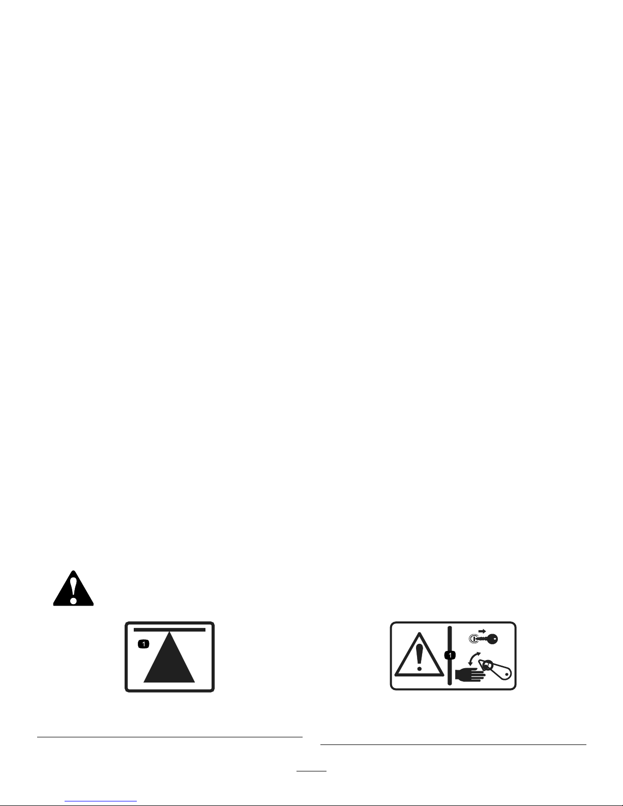
950832
1.Tirepressure
950889
1.Warning—hotsurfaces.
111-0773
1.Warning—crushingofngers,forceappliedfromside.
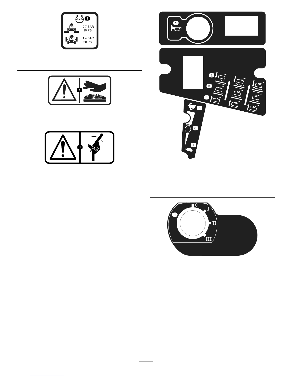
111-3277
1.Horn5.Fast
2.Cutters—lower/oat
6.Enginespeed
3.Cutters—hold7.Slow
4.Cutters—raise
111-3344
1.Ignitionswitch
8
Page 9
111-3562
1.Presspedaltoadjuststeeringwheeltilt.
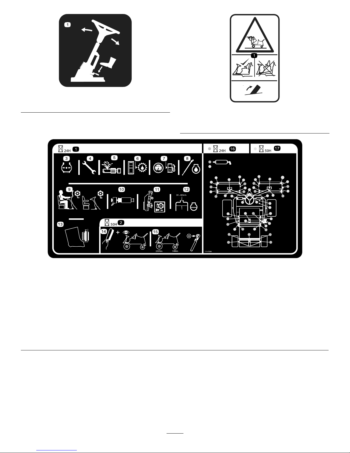
111-3566
1.Falling,crushinghazard—ensureoperatorplatformlatchis
engagedbeforeoperating.
111-7249
1.Dailyserviceinterval
6.Checkhydraulicoillevel11.Checkcutterheadsetting16.Lubricationpointsfordaily
interval
2.50hourserviceinterval
7.Checkfuellevel12.Checkenginecoolantlevel17.Lubricationpointsfor50
hourinterval
3.Checkthetirepressure8.Checkengineoillevel13.Checkcleanlinessof
radiator
4.Checkallnutsandboltsfor
propertightness
9.Checkoperationofseat
switch
14.Cleanandinspectthe
machine
5.Checkallhosesforleaks10.Checkairlterelement15.Checkwheelnuttightness
usingatorquewrench,
Frontwheels200N-m,
Rearwheels54N-m
9
Page 10
111-3567
1.Pedaloperation
111-3902
1.Warning—cuttinghazardofhand,fan.
2.Hotsurfaces—readtheOperator'sManualformore
information.
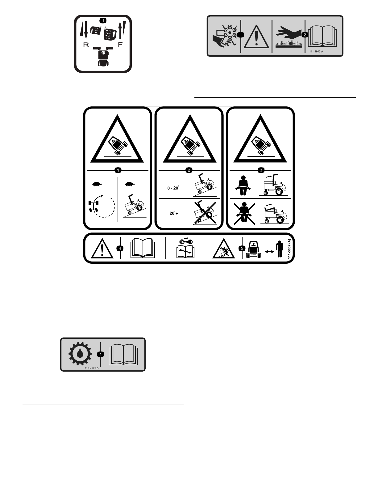
111–5007
1.Tippinghazard—slowmachinebeforeturningandwhenusingonslopes.
2.Tippinghazard—operateonslopeslessthan20degrees,donotoperateonslopesgreaterthan20degrees.
3.Tippinghazard—alwaysweartheseatbeltwhenarolloverprotectionsystem(ROPS)isinuse,donotwearaseatbeltwhen
theROPSbarislowered.
4.Warning—readtheOperator'sManual,removetheignitionkeybeforeperforminganymaintenance.
5.Thrownobjecthazard—keepbystandersasafedistancefromthemachine.
111-3901
1.Transmissionoil—readtheOperator'sManualformore
information.
10
Page 11
Setup
MediaandAdditionalParts
Description
Qty.
Use
Operator'sManual
1
Engineoperator’smanual1
Readthemanualsbeforeoperatingthemachine.
PartsCatalog
1Usethepartscatalogtolookupandorderparts.
CEcerticate
1
ThecerticateindicatesCEcompliance.
Storealldocumentationinasafeplaceforfutureuse.
Note:Determinetheleftandrightsidesofthemachine
fromthenormaloperatingposition.
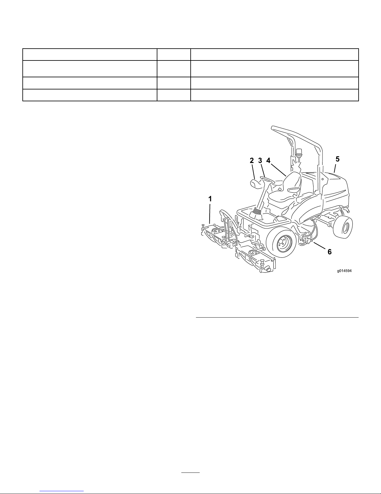
ProductOverview
g014594
1
2 3 4
5
6
Figure2
1.Frontcuttingunits
4.Operator'sseat
2.Controlarm
5.Enginehood
3.Steeringwheel
6.Rearcuttingunit
11
Page 12
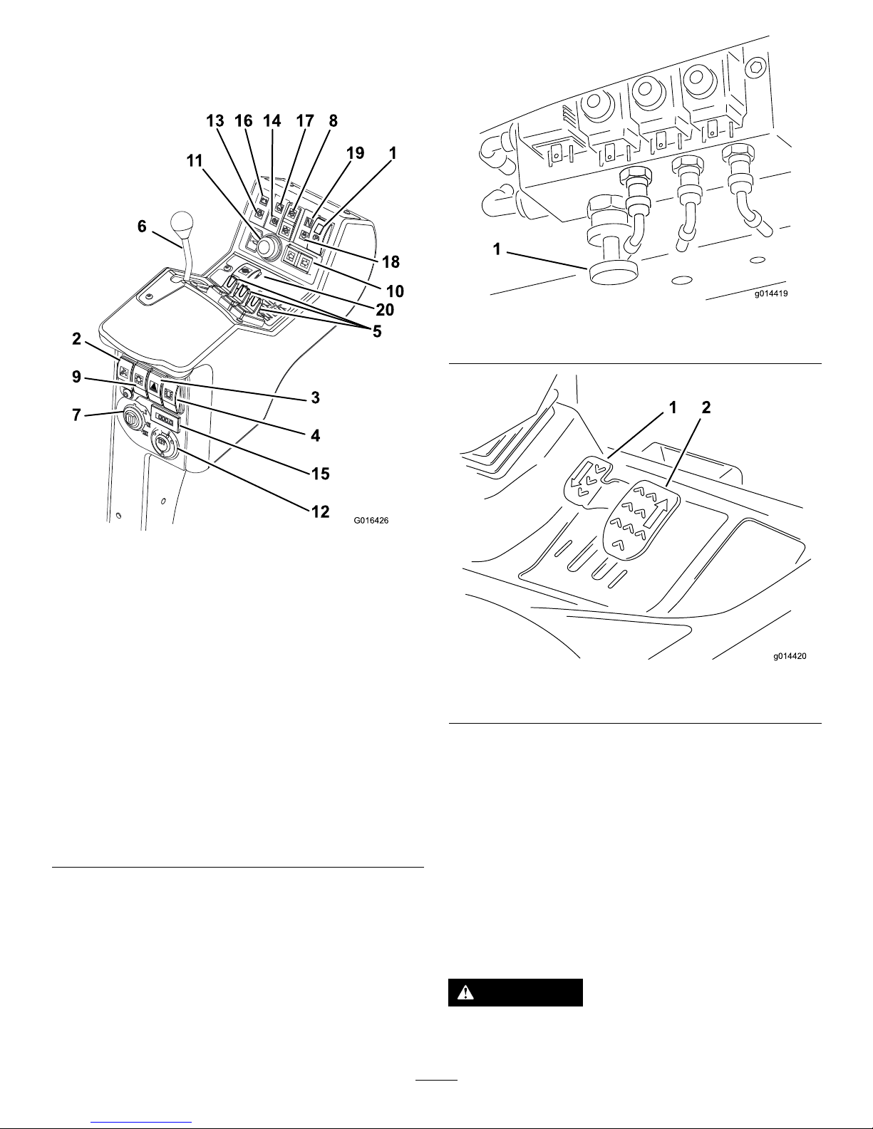
Controls
ControlPanelComponents
6
13 16 14 17 8
G016426
18
10
5
19 1
2
9
7
3
4
15
12
11
20
Figure3
1.Parkingbrakeswitch11.Hornbutton
2.Limitedliftinreverse
switch
12.Auxiliary12voltsocket
(suppliedwitha12Vkit)
3.Hazardwarningswitch
(suppliedwithlightingkit)
13.Engineoilpressure
indicator
4.Warningbeaconswitch
(suppliedwithbeaconkit)
14.Transmissiontemperature
indicator
5.Cutterheadsposition
controls
15.Hourmeter
6.Throttlecontrollever16.Batterywarningindicator
7.Ignitionswitch17.Enginetemperature
warningindicator
8.Cutterheadsdriveswitch18.Glowplugindicator
9.Lightingswitch(supplied
withlightingkit)
19.Transmissionneutral
indicator
10.Directionindicatorswitch
(suppliedwithlightingkit)
20.Differentiallockswitch
g014419
1
Figure4
1.Weighttransfercontrol
g014420
1 2
Figure5
1.Reversetravelpedal2.Forwardtravelpedal
BrakingSystem
ParkingBrake
Movetheparkingbrakeswitchtotheforwardpositionby
pressingthesmallerlockingbuttonandmovingtheswitch
forwardtoengagetheparkingbrake(Figure6).
Note:Donotoperatethemowerwiththeparkingbrake
engagedanddonotengagetheparkingbrakewhilethe
mowerismoving.
Thislightilluminateswhentheparkingbrakeisengagedand
theignitionkeyisturnedtopositionI.
WARNING
Theparkingbrakeoperatesonthefrontwheels
only.Donotparkthemoweronaslope.
12
Page 13
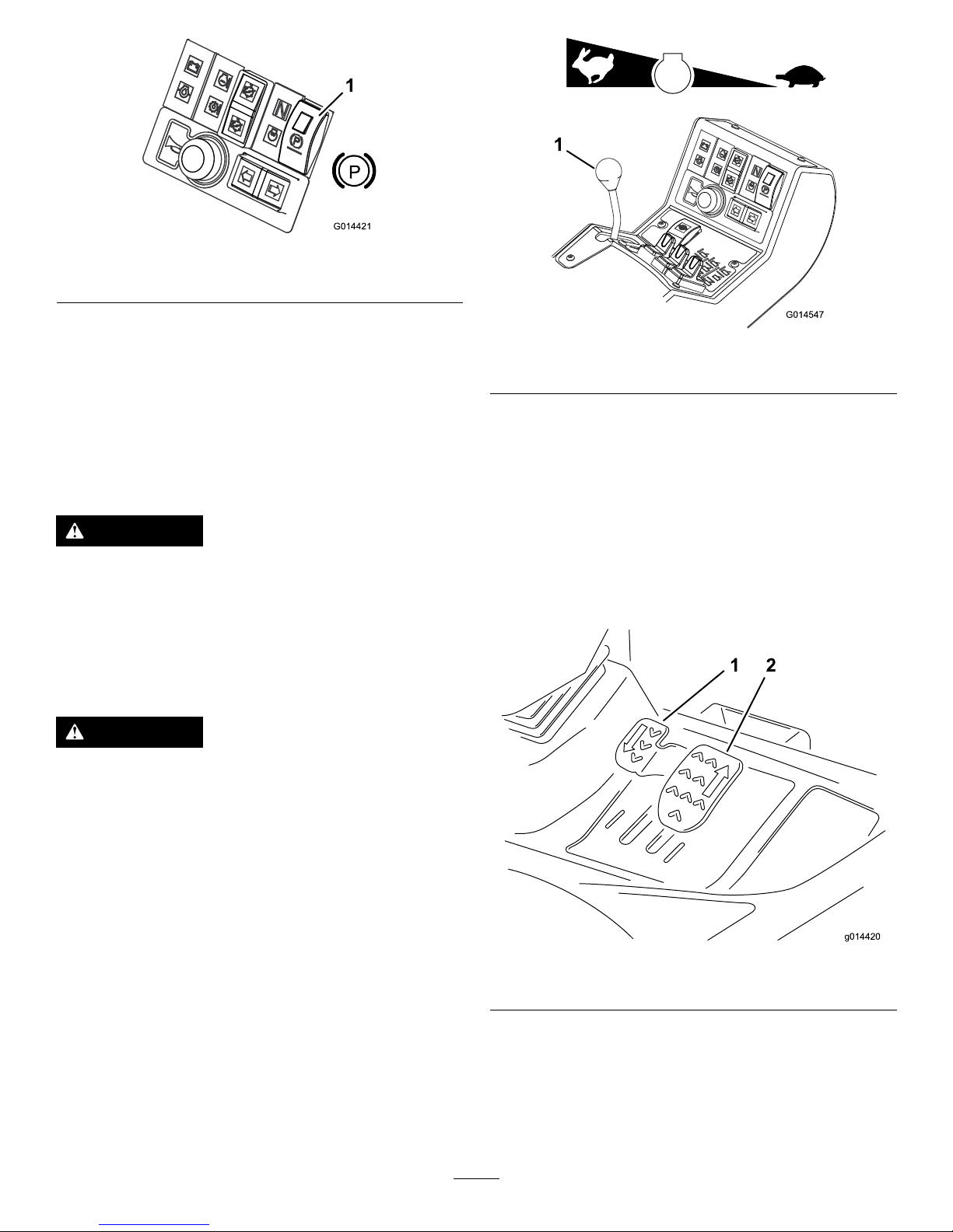
G014421
1
P
Figure6
1.Parkingbrake
ServiceBrake
Servicebrakingisachievedbythehydraulictransmission
system.Whentheforwardorreversetravelpedalsare
releasedortheenginespeedisreduced,servicebraking
becomeseffectiveandtravelspeedisautomaticallyreduced.
Toincreasethebrakingeffect,pushthetransmissionpedal
intotheneutralposition.Servicebrakingiseffectiveonthe
frontwheelsonly.
WARNING
Theservicebrakingsystemwillnotholdthemower
atastandstill.Alwaysensurethattheparkingbrake
isengagedtoparkthemoweratastandstill.
EmergencyBrake
Intheeventofservicebrakefailure,turntheignitionoffto
bringthemowertoastandstill.
WARNING
Takecarewhenusingtheemergencybraking.
Remainseatedandholdontothesteeringwheel
topreventejectionfromthemowercausedbythe
frontwheelbrakesbeingappliedsuddenlywhen
travelling.
ThrottleControl
Operatethethrottlecontrolinaforwarddirectiontoincrease
theenginespeed.Operatethethrottlecontrolinarearward
directiontoreduceenginespeed(Figure7).
Note:Theenginespeeddictatesthespeedoftheother
functions,i.e.travel,cuttingcylinderrotationspeed,and
cutterheadliftspeed.
G014547
1
Figure7
1.Throttlecontrollever
Travel
Forwardtravel:Presstheforwardtravelpedaltoincrease
forwardtravelspeed.Releasethepedaltoreducespeed
(Figure8).
Reversetravel:Pressthereversetravelpedaltoincrease
reversetravelspeed.Releasethepedaltoreducespeed
(Figure8).
Stop(Neutral):Releasetheforwardorreversetravelpedal.
g014420
1 2
Figure8
1.Reversetravelpedal2.Forwardtravelpedal
13
Page 14
DifferentialLock
WARNING
Theturningradiusincreaseswhenthedifferential
lockisengaged.Usingthedifferentiallockathigh
speedmayleadtolossofcontrolandcauseserious
injuryand/orpropertydamage.
Donotusethedifferentiallockathighspeed.
Usethedifferentiallocktopreventexcessivewheelspinwhen
thedrivewheelslosetraction.Thedifferentiallockoperates
inbothforwardandreverse.Youcanlockthedifferential
whilethemachineistravelingslowly.Enginepowerdemand
increaseswhenthedifferentialislocked.Preventexcessive
powerrequirementsbyusingthedifferentiallockonlyatlow
speed.
Tolockthedifferential,pressthedifferentiallockswitch.
Tounlockthedifferential,releasethedifferentiallockswitch.
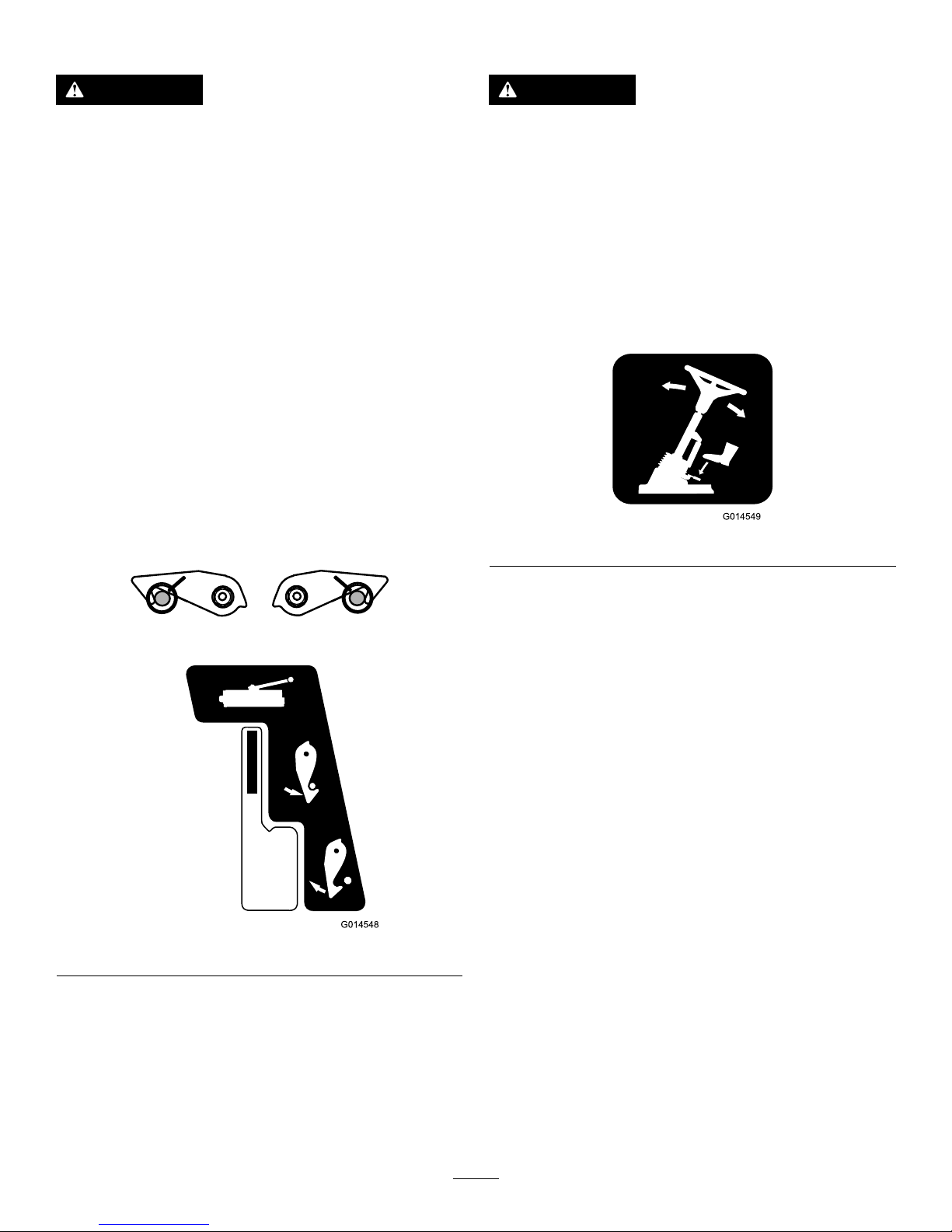
TransportLatches
Alwaysraisethecutterheadstothetransportpositionand
securewiththetransportlatchesandsafetylockswhen
travellingbetweenworkareas(Figure9).
G014548
Figure9
CutterheadDriveSwitch
AlwaysputthecutterheaddriveswitchintheOffposition
whentravellingbetweenworkareas.
AdjustableSteeringColumn
WARNING
Neveroperatethemowerwithoutrstcheckingthat
thesteeringcolumnadjustermechanismisingood
workingorderandthat,onceadjustedandlocked,
thesteeringwheelremainssecurelyinposition.
Adjustmentofthesteeringwheelandsteeringcolumnshould
onlybecarriedoutwhenthemowerisatastandstillwith
theparkingbrakeengaged.
1.Totiltthesteeringwheel,pressthefootpedaldown.
2.Positionthesteeringtowertothemostcomfortable
positionandreleasethepedal(Figure10).
G014549
Figure10
14
Page 15
OperatorSeat
WARNING
Neveroperatethemowerwithoutrstchecking
thattheoperatorseatmechanismsareingood
workingorderandthat,onceadjustedandlocked,
theseatremainssecurelyinposition.
Adjustmentoftheseatmechanismsshouldonlybe
carriedoutwhenthemowerisatastandstillwith
theparkingbrakeengaged.
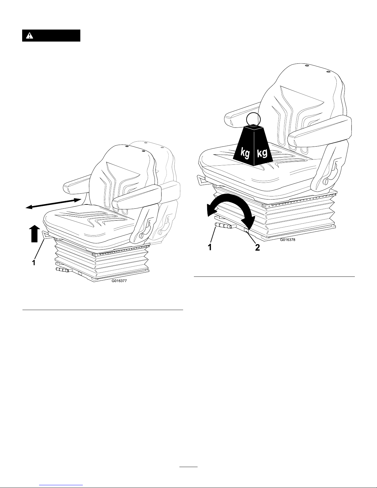
•Fore/AftAdjustment:Movetheleverupwardtoadjust
thefore/aftpositionoftheseat.Releasethelevertolock
theseatinposition(Figure11).
1
G016377
Figure11
1.Lever
•Operatorweightadjustment:Rotatethehandle
clockwisetoincreasesuspensionstiffnessand
counterclockwisetodecreasethestiffness.Thedial
indicateswhentheoptimumsuspensionadjustmenthas
beensetaccordingtooperatorweight(kg);refertoFigure
12.
1
2
G016378
Figure12
1.Lever2.Dial
15
Page 16
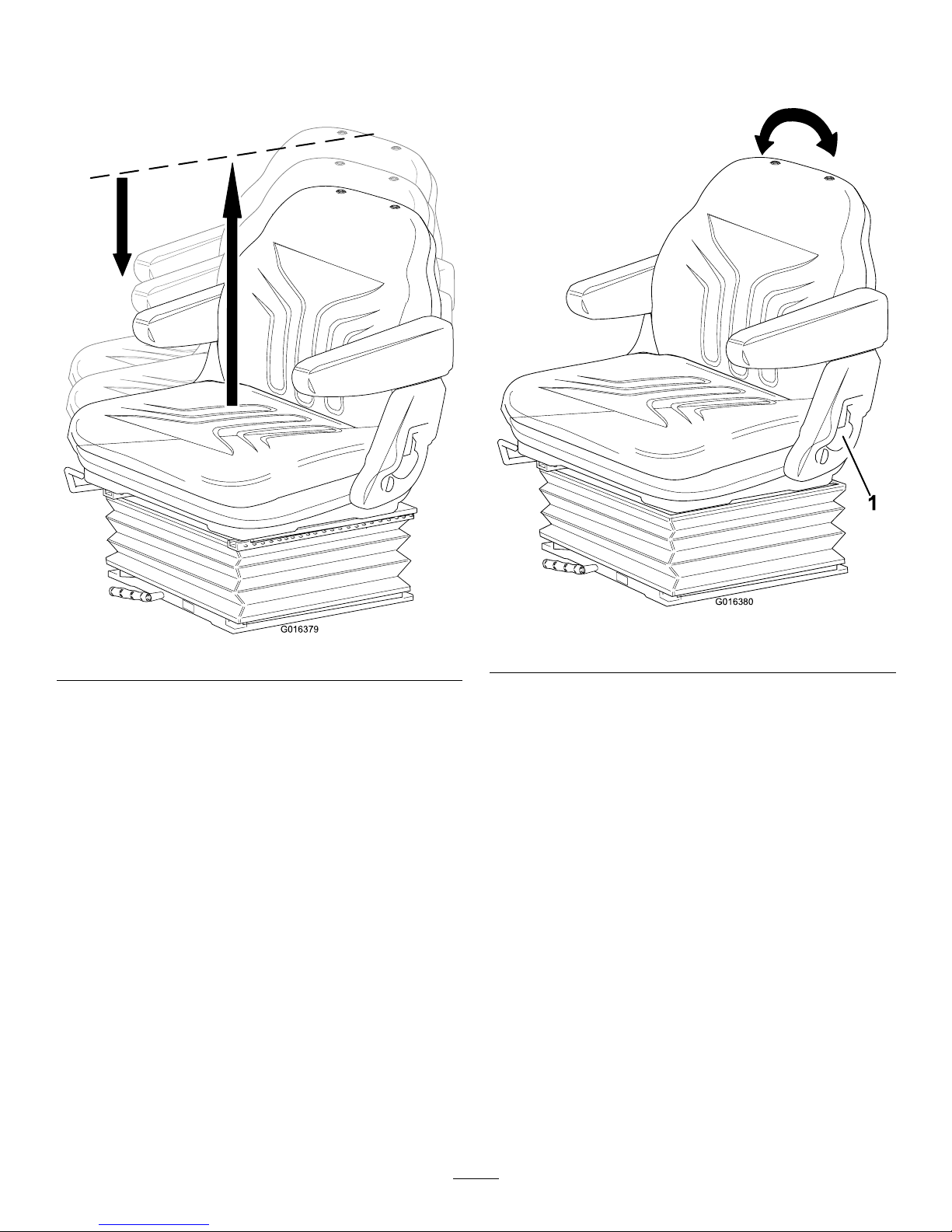
•Heightadjustment:Manuallylifttheseatfor
incrementalheightadjustment.Tolowertheseat,liftit
beyondthehighestsetting,thenallowittodroptothe
lowestsetting(Figure13).
G016379
Figure13
•Backrestadjustment:Pullthehandleoutwardtoadjust
theseatbackrestangle.Releasethehandletolockthe
seatbackrestinposition(Figure14).
1
G016380
Figure14
1.Handle
16
Page 17
WarningSystems
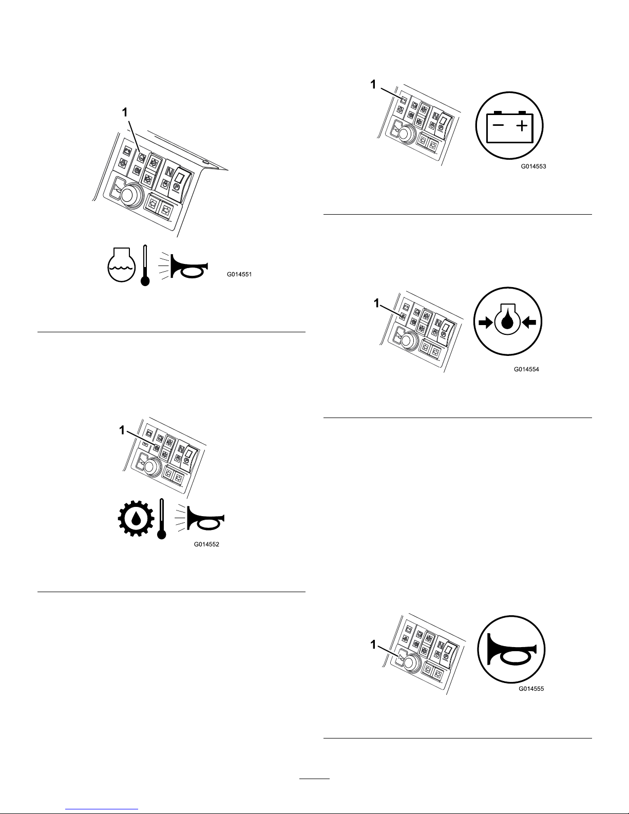
EngineCoolantOverheatingWarningLight
Theenginecoolantwarninglightilluminates,thehornis
actuatedandthecuttersstop(Figure15).
1
G014551
Figure15
1.Enginecoolantoverheatingwarninglight
HydraulicOilOverheatingWarningLight
Thehydraulicoilwarninglightilluminateswhenoverheating
occursandthehornisactuatedwhenthehydraulicoilinthe
reservoirexceeds95degreesC(203degreesF)(Figure16).
1
G014552
Figure16
1.Hydraulicoiloverheatingwarninglight
LowBatteryChargeWarningLight
Thebatterychargewarninglightilluminateswhenlowbattery
chargeoccurs(Figure17).
1
G014553
Figure17
1.Lowbatterychargewarninglight
LowEngineOilPressureWarningLight
Theengineoilpressurewarninglightilluminateswhentheoil
pressureistoolow(Figure18).
1
G014554
Figure18
1.Lowengineoilpressurewarninglight
DisengagementofCuttingCylinders
Thecuttingcylinderswilldisengagewhentheoperating
temperaturereaches115degreesC.
AudibleWarningHorn
Pressthehornbuttontoprovideanaudiblewarning(Figure
19).
Important:Thehornisautomaticallyactuatedwhen
anenginecoolantorhydraulicoiloverheatcondition
occurs.Stoptheengineimmediatelyandxthemachine
beforestartingitagain.
1
G014555
Figure19
1.Horn
17
Page 18
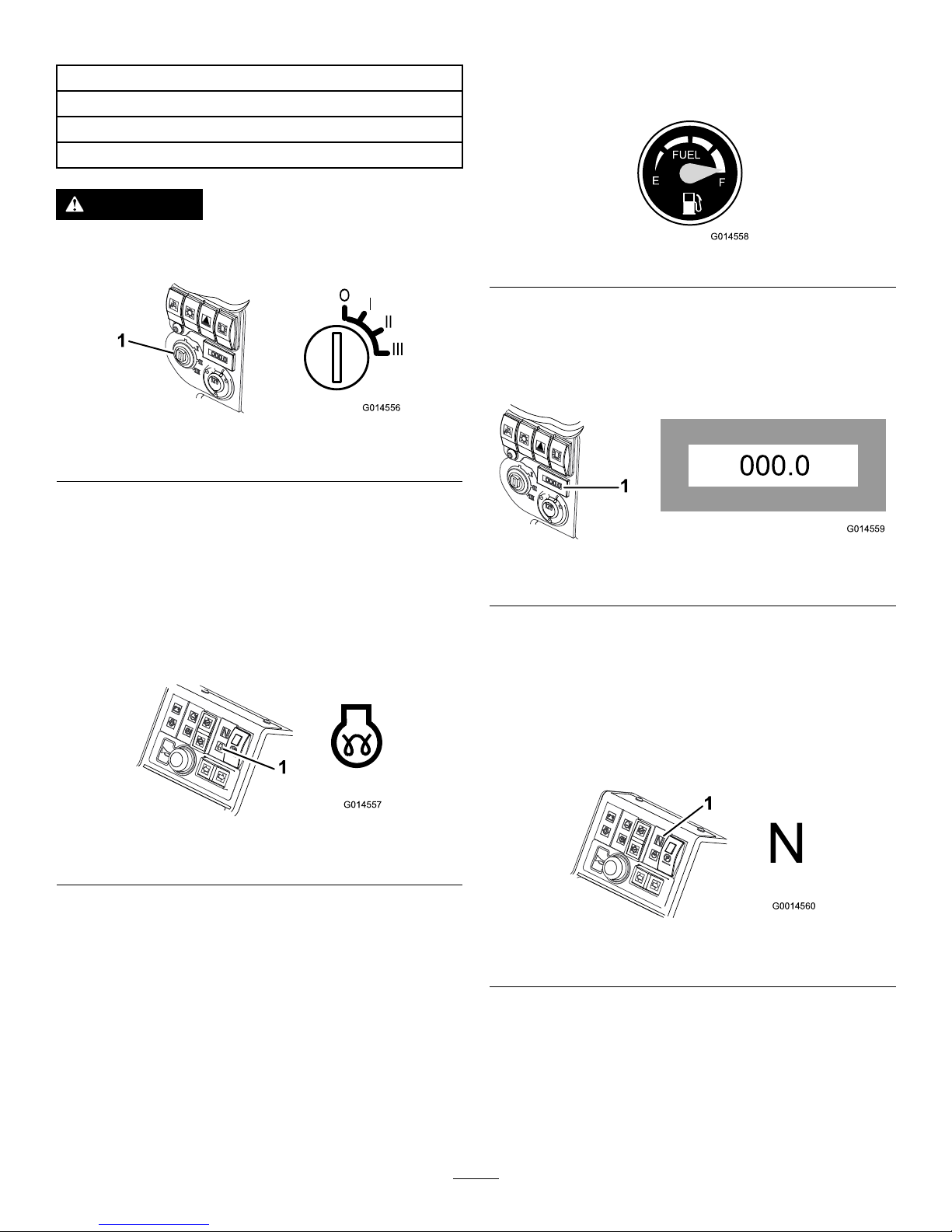
IgnitionKey
0=Engineoff
I=Enginerun/Auxiliaryon
II=Enginepre-heat
III=Enginestart
WARNING
Alwaysremovetheignitionkeywhenthemoweris
notinuse.
G014556
1
I
II
III
Figure20
1.Ignitionswitch
EnginePre-HeatIndicatorLight
TurntheignitionkeytopositionII.Theenginepreheat
indicatorlightwillilluminateandheattheglowplugs
(Figure21).
Important:Attemptingtostartacoldenginebefore
thepre-heatisusedcancauseunnecessaryweartothe
battery.
1
G014557
Figure21
1.Enginepre-heatindicatorlight
FuelGauge
Thefuelgaugeshowstheamountoffuelinthetank
(Figure22).
G014558
FUEL
E
F
Figure22
HourMeter
Thehourmetershowsthetotalhoursthatthemachinehas
beenoperated(Figure23).
1
G014559
000.0
Figure23
1.Hourmeter
TransmissionNeutralIndicatorLight
Thislightilluminateswhenthetravelcontrolpedalisinthe
neutralpositionandtheignitionkeyisturnedtopositionI
(Figure24).
Note:Theparkingbrakemustbeengagedforthe
transmissionneutralindicatorlighttoilluminate.
G0014560
1
Figure24
1.Transmissionneutralindicatorlight
18
Page 19

CutterheadDriveSwitchIndicatorLight
Thislightilluminateswhenthecutterheaddriveswitchisin
theforward/reversepositionandtheignitionkeyisturnedto
positionI(Figure25).
1
G0014561
Figure25
1.CutterheadDriveSwitchIndicatorLight
Specications
Note:Specicationsanddesignaresubjecttochangewithoutnotice.
Specication
LT3340
TransportWidth
157.5cm(62inches)
Widthofcut212.0cm(83.5inches)
Length
286.0cm(112.6inches)
Height
168.1cm(66.2inches)withROPSfolded
216.0cm(85.0inches)withROPSinitsverticaloperatingposition
Weight
1325kg(2921lb)*
Withuidsand250mm6bladecutterheads
Engine
Kubota26.5kw(35.5hp)at3000rpmDIN70020
Fueltankcapacity
45litres(11.9USgallons)
Transportspeed
25km/h(15.5mph)
Mowingspeed
11km/h(6.85mph)
Hydraulicsystemcapacity
32liters(8.5USgallons)
Enginespeed3000rpm
Attachments/Accessories
AselectionofToroapprovedattachmentsandaccessoriesisavailableforusewiththemachinetoenhanceandexpandits
capabilities.ContactyourAuthorizedServiceDealerorDistributor.
TobestprotectyourinvestmentandmaintainoptimalperformanceofyourToroequipment,countonTorogenuineparts.
Whenitcomestoreliability,Torodeliversreplacementpartsdesignedtotheexactengineeringspecicationofourequipment.
Forpeaceofmind,insistonT orogenuineparts.
19
Page 20

Operation
Note:Determinetheleftandrightsidesofthemachine
fromthenormaloperatingposition.
CAUTION
Ifyouleavethekeyintheignitionswitch,someone
couldaccidentlystarttheengineandseriously
injureyouorotherbystanders.
Lowerthecuttingunitstotheground,setthe
parkingbrakeandremovethekeyfromtheignition
switchbeforeservicingormakingadjustmentsto
themachine.
CheckingtheEngine-OilLevel
ServiceInterval:Beforeeachuseordaily
Theengineisshippedwithoilinthecrankcase;however,the
oillevelmustbecheckedbeforeandaftertheengineisrst
started.
Crankcasecapacity:approximately6.0L(6.3USqt)with
thelter
Usehigh-qualityengineoilthatmeetsthefollowing
specications:
•APIClassicationLevelRequired:CH-4,CI-4orhigher
•Preferredoil:SAE15W-40(above0degreesF)
•Alternateoil:SAE10W-30or5W-30(alltemperatures)
ToroPremiumEngineoilisavailablefromyourdistributorin
either15W -40or10W-30viscosity .
Note:Thebesttimetochecktheengineoiliswhenthe
engineiscoolbeforeithasbeenstartedfortheday.Ifithas
alreadybeenrun,allowtheoiltodrainbackdowntothe
sumpforatleast10minutesbeforechecking.Iftheoillevel
isatorbelowtheaddmarkonthedipstick,addoiltobring
theoilleveltothefullmark.Donotoverllthecrankcase.
Iftheoillevelisbetweenthefullandaddmarks,nooil
additionisrequired.
1.Parkthemachineonalevelsurface,stoptheengine,
settheparkingbrakeandremovethekeyfromthe
ignitionswitch.
2.Openthehood.
3.Removethedipstick,wipeitclean,andinstallit
(Figure26).
Figure26
1.Dipstick
4.Removedipstickandcheckoillevelondipstick.
TheoillevelshouldbeuptotheFullmark.
5.IftheoillevelisbelowtheFullmark,removethell
cap(Figure27)andaddoiluntillevelreachestheFull
markondipstick.Donotoverll.
Figure27
1.Oilllcap
6.Installtheoilllcapandclosethehood.
20
Page 21

CheckingtheCoolingSystem
ServiceInterval:Beforeeachuseordaily
CAUTION
Iftheenginehasbeenrunning,thepressurized,hot
coolantcanescapeandcauseburns.
•Donotopentheradiatorcapwhentheengine
isrunning.
•Usearagwhenopeningtheradiatorcap,and
openthecapslowlytoallowsteamtoescape.
Thecoolingsystemislledwitha50/50solutionofwater
andpermanentethyleneglycolantifreeze.
1.Cleandebrisoffofthescreen,oilcooler,andfront
oftheradiatordailyandmoreoftenifconditionsare
extremelydustyanddirty.RefertoRemovingDebris
fromtheCoolingSystem(page43).
2.Checkthelevelofthecoolantintheexpansiontank
(Figure28).
Note:Thecoolantlevelshouldbebetweenthemarks
onthesideofthetank.
1
g025068
Figure28
1.Expansiontank
3.Ifthecoolantlevelislow,removetheexpansion-tank
capandreplenishthesystem.
Note:Donotoverll.
4.Installtheexpansion-tankcap.
AddingFuel
ServiceInterval:Beforeeachuseordaily
Useonlyclean,freshdieselfuelwithlow(<50ppm)or
ultra-low(<15ppm)sulfurcontent.Theminimumcetane
ratingshouldbe40.Purchasefuelinquantitiesthatcanbe
usedwithin180daystoensurefuelfreshness.
Fueltankcapacity:45L(11.9USgallons)
Usesummergradedieselfuel(No.2-D)attemperatures
above-7°C(20°F)andwintergrade(No.1-DorNo.
1-D/2-Dblend)belowthattemperature.Useofwintergrade
fuelatlowertemperaturesprovideslowerashpointand
coldowcharacteristicswhichwilleasestartingandreduce
fuellterplugging.
Useofsummergradefuelabove-7°C(20°F)willcontribute
towardlongerfuelpumplifeandincreasedpowercompared
towintergradefuel.
Important:Donotusekeroseneorgasolineinsteadof
dieselfuel.Failuretoobservethiscautionwilldamage
theengine.
WARNING
Fuelisharmfulorfatalifswallowed.Long-term
exposuretovaporscancauseseriousinjuryand
illness.
•Avoidprolongedbreathingofvapors.
•Keepfaceawayfromnozzleandfueltankor
conditioneropening.
•Keepfuelawayfromeyesandskin.
DANGER
Incertainconditions,fuelisextremelyammable
andhighlyexplosive.Areorexplosionfromfuel
canburnyouandothersandcandamageproperty.
•Fillthefueltankoutdoors,inanopenarea,when
theengineiscold.Wipeupanyfuelthatspills.
•Neverllthefueltankinsideanenclosedtrailer.
•Neversmokewhenhandlingfuel,andstayaway
fromanopenameorwherefuelfumesmaybe
ignitedbyaspark.
•Storefuelinanapprovedcontainerandkeepit
outofthereachofchildren.Neverbuymore
thana180-daysupplyoffuel.
•Donotoperatemachinewithoutentireexhaust
systeminplaceandinproperworkingcondition.
21
Page 22

DANGER
Incertainconditionsduringfueling,static
electricitycanbereleased,causingasparkwhich
canignitethefuelvapors.Areorexplosionfrom
fuelcanburnyouandothersandcandamage
property.
•Alwaysplacefuelcontainersonthegroundaway
fromyourvehiclebeforelling.
•Donotllfuelcontainersinsideavehicleoron
atruckortrailerbedbecauseinteriorcarpets
orplastictruck-bedlinersmayinsulatethe
containerandslowthelossofanystaticcharge.
•Whenpractical,removeequipmentfromthe
truckortrailerandfueltheequipmentwiththe
wheelsontheground.
Ifthisisnotpossible,thenfuelsuchequipment
onatruckortrailerfromaportablecontainer,
ratherthanfromafueldispensernozzle.
•Ifafueldispensernozzlemustbeused,keepthe
nozzleincontactwiththerimofthefueltank
orcontaineropeningatalltimesuntilfuelingis
complete.
1.Parkthemachineonalevelsurface.
2.Usingacleanrag,cleantheareaaroundthefueltank
cap.
3.Removethecapfromthefueltank.
4.Fillthetankuntilthelevelistothebottomoftheller
neckwithdieselfuel.
5.Installthefueltankcaptightlyafterllingthetank.
Note:Ifpossible,llthefueltankaftereachuse.This
willminimizepossiblebuildupofcondensationinside
thefueltank.
CheckingtheHydraulicFluid
Thereservoirislledatthefactorywithapproximately32
L(8.5USgallons)ofhigh-qualityhydraulicuid.Thebest
timetocheckthehydraulicoiliswhentheuidiscold.The
machineshouldbeinitstransportconguration.Iftheoil
levelisbelowthe‘add’markonthedipstick,addoiltobring
theoilleveltothemiddleoftheacceptablerange.Donot
overllthereservoir.Iftheoillevelisbetweenthe‘full’and
the‘add’marks,nooiladditionisrequired.
Therecommendedreplacementuidis:
ToroPremiumAllSeasonHydraulicFluid
(availablein19liter(5USgallon)containersor208liter(55
USgallon)drums—seethepartsdocumentationoryourT oro
distributorforpartnumbers)
Alternativeuids:IftheTorouidisnotavailable,other
conventional,petroleum-baseduidsmaybeused,provided
thattheymeetallofthefollowingmaterialpropertiesand
industryspecications.Checkwithyouroilsuppliertosee
whethertheoilmeetsthesespecications.
Note:Torowillnotassumeresponsibilityfordamage
causedbyimpropersubstitutions,souseonlyproducts
fromreputablemanufacturerswhowillstandbehindtheir
recommendation.
HighViscosityIndex/LowPourPointAntiwearHydraulic
Fluid,ISOVG46Multigrade
MaterialProperties:
Viscosity,ASTMD445cSt@40°C(104°F)
44to48
cSt@100°C(212°F)
7.9to9.1
Viscosityindex,ASTM
D2270
140orhigher(high
viscosityindexindicatesa
multiweightuid)
Pourpoint,ASTMD97-36.7°Cto-45°C(-34°Fto
-49°F)
FZG,failstage
11orbetter
Watercontent(newuid)500ppm(maximum)
IndustrySpecications:
VickersI-286-S,VickersM-2950-S,DenisonHF-0,
Vickers35VQ25(EatonATS373-C)
Theproperhydraulicuidsmustbespeciedfor
mobilemachinery(asopposedtoindustrialplantusage),
multiweight-type,withZnDTPorZDDPantiwearadditive
package(notanashless-typeuid).
Important:Manyhydraulicuidsarealmostcolorless,
makingitdifculttospotleaks.Areddyeadditivefor
thehydraulicsystemoilisavailablein20ml(2/3oz)
bottles.Onebottleissufcientfor15to22liters(4to6
USgallons)ofhydraulicoil.Orderpart44-2500from
yourAuthorizedT oroDistributor.
Synthetic,BiodegradableHydraulicFluid
(availablein19liter(5USgallon)containersor208liter(55
USgallon)drums—seethepartsdocumentationoryourT oro
distributorforpartnumbers)
Thishigh-quality,synthetic,biodegradableuidhasbeen
testedandfoundcompatibleforthisToromodel.Other
brandsofsyntheticuidmayhavesealcompatibilityproblems
andTorocannotassumeresponsibilityforunauthorized
substitutions.
Note:Thissyntheticuidisnotcompatiblewiththe
ToroBiodegradableFluidpreviouslysold.SeeyourToro
Distributorformoreinformation.
Alternativeuids:
•MobilEALEnvirosynH46(US)
•MobilEALHydraulicOil46(international)
1.Positionthemachineonalevelsurface,lowerthe
cuttingunits,andstoptheengine.
2.Checkthesightlevelgaugeonthesideofthetank.
Note:Thelevelneedstobeattheuppermark.
22
Page 23

3.Ifadditionalhydraulicoilisneeded,cleanthearea
aroundthellerneckandthecapofthehydraulictank
(Figure29)andremovethecap.
2
1
G014570
3
Figure29
1.Hydraulic-tankcap
2.Oiltank
3.Sightlevelgauge
4.Removethecapandllthetanktotheuppermark
onthesightlevelgauge.
Note:Donotoverllthetank.
5.Installthecapontothetank.
CheckingtheTirePressure
Checktheairpressureinthefrontandreartires.Refertothe
chartbelowforthecorrectpressure.
Important:Maintaincorrecttirepressureinalltiresto
ensurecorrectcontactwiththeturf.
RecommendedTirePressures TiresTireType
Turf
Conditions
Road
Conditions
Maximum
Pressure
FrontAxle26x
12.0-12
BKTturf
pattern
0.7bar(10
psi)
1.4bar(20
psi)
1.7bar(25
psi)
RearAxle20x10.0-
8BKTturf
pattern
0.7bar(10
psi)
1.4bar(20
psi)
1.7bar(25
psi)
CheckingtheTorqueofthe
WheelNuts
ServiceInterval:Beforeeachuseordaily
Torquethewheelnutsto200N-m(148ft-lb)forthefront
axle,and54N-m(40ft-lb)fortherearaxle.
WARNING
Failuretomaintainpropertorqueofthewheelnuts
couldresultinpersonalinjury.
Ensurethatthewheelnutsaretorquedproperly.
ThinkSafetyFirst
Carefullyreadallsafetyinstructionsandsymbolsinthe
safetysection.Knowingthisinformationcouldhelpyouor
bystandersavoidinjury.
DANGER
Operatingonwetgrassorsteepslopescancause
slidingandlossofcontrol.
Wheelsdroppingoveredgescancauserollovers,
whichmayresultinseriousinjury,death,or
drowning.
Thereisnorolloverprotectionwhentherollbaris
down.
Alwayskeeptherollbarinthefullyraisedand
lockedpositionandusetheseatbelt.
Readandfollowtherolloverprotectioninstructions
andwarnings.
Toavoidlossofcontrolandpossibilityofrollover:
•Donotoperateneardrop-offsornearwater.
•Donotoperateonslopesgreaterthan20degrees.
•Reducespeedanduseextremecautionon
slopes.
•Avoidsuddenturnsorrapidspeedchanges.
CAUTION
Thismachineproducessoundlevelsthatcancause
hearinglossthroughextendedperiodsofexposure.
Wearhearingprotectionwhenoperatingthis
machine.
Theuseofprotectiveequipmentforeyes,ears,hands,feet,
andheadisrecommended.
G009027
1
2
Figure30
1.Wearsafetyglasses.
2.Wearhearingprotection.
23
Page 24

UsingtheOperatorPlatform
LatchingMechanism
Donotoperatethemowerwithoutrstcheckingthatthe
operatorplatformlatchingmechanismisfullyengagedand
ingoodworkingorder.
WARNING
Neveroperatethemowerwithoutrstchecking
thattheoperatorplatformlatchingmechanismis
fullyengagedandingoodworkingorder.
ReleasingthePlatform
1.Movethelockinglatchhandletowardsthefrontofthe
moweruntilthelatchhooksclearthelockingbar.
2.Raisetheplatform.Thegasspringwillprovide
assistance.
SecuringthePlatform
1.Lowertheplatformcarefully .
Note:Thegasspringwillprovideassistance.
2.Movethelockinglatchhandletowardsthefrontofthe
mowerastheplatformnearsthefullyloweredposition.
Note:Thiswillensurethatthelatchhooksclearthe
lockingbar.
3.Fullylowertheplatformandmovethelockinghandle
towardstherearofthemoweruntilthelatchhooks
fullyengagethelockingbar.
G014422
Figure31
UnderstandingtheOperator
PresenceControls
Note:Theenginestopsiftheoperatorleavestheseat
withoutengagingtheparkingbrake.
EngineStartLockout:Theenginecanonlybestartedwhen
theforward/reversetravelpedalisintheNeutralposition,
thecutterheaddriveswitchisintheOffpositionandthe
parkingbrakeisengaged.Whenthesecircumstancesare
satised,switchesareactivatedpermittingtheenginetobe
started.
EngineRunInterlock:Oncetheengineisstartedthe
operatormustbeseatedbeforetheparkingbrakeisreleased
fortheenginetocontinuetorun.
CuttingCylinderDriveLockout:Thedrivetothecutting
cylindersisonlypossiblewhentheoperatorisseated.Ifthe
operatorraisesofftheseatforaperiodofmorethanone
second,aswitchisactivatedandthedrivetothecutting
cylindersisautomaticallydisengaged.Toengagedrivetothe
cuttingcylinders,theoperatormustreturntotheseat,then
operatethecutterheaddriveswitchtotheOffpositionbefore
movingitbacktotheOnposition.Iftheoperatorrisesoff
theseatforabriefmomentduringnormalwork,drivetothe
cuttingcylindersisnotaffected.
Theenginecanonlybestartedwiththecutterheaddrive
switchintheOffposition.
WARNING
Donotoperatetheturfmoweriftheoperator
presencecontrolsaremalfunctioninginanyway .
Al w ays
replacedamagedorwornpartsandcheck
thattheyfunctioncorrectlybeforeoperatingthe
machine.
CAUTION
Ifsafetyinterlockswitchesaredisconnectedor
damagedthemachinecouldoperateunexpectedly
causingpersonalinjury.
•Donottamperwiththeinterlockswitches.
•Checktheoperationoftheinterlockswitches
dailyandreplaceanydamagedswitchesbefore
operatingthemachine.
StartingandStoppingthe
Engine
Important:Y oumustbleedthefuelsystembefore
startingtheengineifyouarestartingtheengineforthe
rsttime,theenginehasstoppedduetolackoffuel,or
youhaveperformedmaintenanceonthefuelsystem;
refertoBleedingtheFuelSystem.
24
Page 25

WARNING
Operatingthemachineinanunsafemannercould
resultinpersonalinjury.
Beforestartingtheengine,ensurethatthefollowing
conditionsaremet:
•YouhavereadandunderstoodtheSafetysection
inthismanual.
•Theareaisclearofbystanders.
•Thecutterheaddriveisdisengaged.
•Theparkingbrakeisset.
•Thetravelcontrolpedalsareinneutral.
Important:ThismachineisttedwithanEnginestart
lockout;refertoUnderstandingtheOperatorPresence
Controls(page24).
StartingaColdEngine
1.Sitontheseat,keepyourfootoffofthetractionpedals
sothatitisinNeutral,engagetheparkingbrakeand
setthethrottletothe70percentfullthrottleposition.
2.TurntheignitionkeytotheignitiononpositionIand
checkthattheengineoilpressureandbatterycharge
warninglightsilluminate.
3.TurntheignitionkeytothepreheatpositionIIsothat
thepre-heatindicatorlightison.Holditfor5seconds
toheattheglowplugs.
4.Afterpreheatingtheglowplugs,turnkeytothestart
positionIIIandholdtocranktheengine.
Cranktheenginefornolongerthan15seconds.
ReleasetheignitionkeybacktopositionIwhenthe
enginestarts.
5.Runtheengineatlowidlespeeduntilitwarmsup.
1
G014557
Figure32
1.Enginepre-heatindicatorlight
WARNING
Whentheengineisoperatingallwarninglights
shouldbeoff.Ifawarninglightilluminates,stop
theengineimmediatelyandhavethefaultrectied
beforerestarting.
StartingaWarmEngine
1.Sitontheseat,keepyourfootoffofthetractionpedal
sothatitisinNeutral,engagetheparkingbrakeand
setthethrottletothe70percentfullthrottle.
2.TurntheignitionkeytotheignitiononpositionIand
checkthattheengineoilpressureandbatterycharge
warninglightsilluminate.
3.TurntheignitionkeytothestartpositionIIIandhold
tocranktheengine.
Cranktheenginefornolongerthan15seconds.
ReleasetheignitionkeybacktopositionIwhenthe
enginestarts.
4.Runtheengineatlowidlespeeduntilitwarmsup.
StoppingtheEngine
1.MoveallcontrolstoNeutral,settheparkingbrake,
movethethrottletothelowidlepositionandallowthe
enginetoreachlowidlespeed.
Important:Allowtheenginetoidlefor5
minutesbeforeshuttingitoffafterafullload
operation.Failuretodosomayleadtotroubleon
aturbo-chargedengine.
2.Lettheengineidlefor5minutes.
3.Turntheignitionkeytoposition0.
Iftheenginefailstostopwhentheignitionkeyis
turnedto0,operatetheenginestopleverinforward
direction(Figure33).
WARNING
Keephandsclearofmovingobjectsandhot
enginepartswhiletheengineisrunning.
G014563
Figure33
25
Page 26

UsingtheGrassDeectors
Thereargrassdeectorsmustalwaysbecorrectlytted.The
deectorsshouldbesetaslowaspossibletodeectgrass
dischargetotheground(Figure34).
G014425
Figure34
AdjustingtheCenter
CutterheadHeight-of-Cut
Correction
WithallcutterheadssetatthesameHOCviatheindicator
rings,itmaybenoticeablethatthecenterunitproducesa
highercutnishcomparedtothewingunits.Thecenter
unitispulledandthewingunitsarepushed;thispresents
marginallydifferentcuttinganglesrelativetotheground.The
amountofHOCvariationwhichresultsfromthiswillbe
inuencedbytheterrain,butsatisfactoryresultscanusually
beachievedbysettingthecentercutterheadHOCindicator
ringlowerthanthewingunitsettings.
ControllingthePositionofthe
IndividualCutterheads
Thecutterheadsmayberaisedorloweredindependently
usingthebankof3liftcontrolswitches.
1.Tolowerthecutterheads,operatetheliftcontrol
switchesinadownwarddirectionandrelease.
Thecutterheaddriveswitchmustbeon(forward)todo
this,thecylinderdrivewillengagewhenthecutterheads
areapproximately150mm(6inches)aboveground
level.Thecutterheadsarenowin‘oat’modeandwill
followthegroundcontours.
2.Toraisethecutterheads,operatetheliftcontrol
switchesinanupwarddirectionandholdinposition3.
IfthecutterheaddriveswitchisintheOnpositionthe
cylinderdrivewilldisengageimmediately .
3.Releasetheliftcontrolswitcheswhenthecutterheads
areattherequiredheight.
Thecontrolswitcheswillautomaticallyreturnto
position2(neutral)andthearmsarehydraulically
lockedintoposition.
AdjustingtheCutterheadAuto
LimitedLift
Toactivate,presstheAutoLimitedLiftswitchtotheOn
position(Figure35).
Todeactivate,presstheAutoLimitedLiftswitchtotheOff
position(Figure35).
Manuallimitedliftusingthe3liftcontrolswitchesisalways
availableregardlessofthepositionoftheAutoswitch.
g014433
Figure35
Toraisethecutterheadstothelimitedliftposition:
momentarilyoperatetheswitchesinanupwarddirection.
Thecylinderdrivewilldisengageimmediatelyandthe
cutterheadswillstopraising,approximately150mm(6
inches)abovegroundlevel.
Thisoperateswiththecutterheadsloweredandrotating.
Autolimitedliftinreversecausesthecutterheadstorise
automaticallytothelimitedliftpositionwhenreversing.They
willreturntotheoatingpositionwhenreturningtoforward
26
Page 27

travel.Thecuttingcylinderscontinuetorotateduringthis
operation.
EngagingtheCutterheadDrive
1
2
3
G014434
Figure36
1.Forward3.Reverse
2.Off
Thecutterheaddrivecanbeengagedonlywhentheoperator
isseatedcorrectly,refertoCheckingtheOperatorPresence
SeatSwitch(page44).
Forwardrotationcutterheaddriveengagement:Pressthe
topofthecutterheaddriveswitchtotheforwardposition
(Figure36).
Reverserotationcutterheaddriveengagement:Pressthe
bottomofthecutterheaddriveswitchtothereverseposition
(Figure36).
Allcutterheaddrivesdisengagement:Settheswitchtothe
middleposition(Figure36).
Tolowerthecutterheads:Thecutterheaddriveswitch
mustbesettoforward.Operatetheliftcontrolswitch(s)
inadownwarddirection.Thecylinderwilldrivewhenthe
cutterheadsareapproximately150mm(6inches)above
groundlevel.
ClearingtheCuttingCylinders
WARNING
Neverattempttorotatethecuttingcylindersby
hand.
•Theremaybesomeresidualpressureinthe
hydraulicsystemwhichcouldcauseinjury
throughsuddenmovementofthecylinder(s)
whentheblockageisreleased.
•Alwayswearprotectiveglovesanduseasuitable
strongwoodeninstrument.
•Ensurethatthewoodeninstrumentwillt
betweenthebladesandthroughthecylinder
andislongenoughtoprovidesufcientleverage
toreleasetheblockage.
1.Stopthemachineonlevelground.
2.Applytheparkingbrakeanddisengagealldrives.
3.Lowerthecuttingunitstothegroundorsecurelylock
inthedesignatedtransportpositions.
4.Stoptheengineandremovetheignitionkeytoisolate
allpowersourcesandcheckthattheyarestopped.
5.Releaseallstoredenergydevices.
6.Checkthatallmovingpartsarestationary.
7.Usingasuitablestrongwoodeninstrument,remove
theblockage.Makesurethatthewoodeninstrumentis
properlysupportedinthecylinderandavoidtheuseof
excessiveforcetopreventdamage.
8.Ensurethatthewoodeninstrumentisremovedfrom
thecuttingcylinderbeforerestartingthepowersource.
9.Repairoradjustthecylinderifrequired.
UsingWeightTransfer/
TractionAssistance
Avariablehydraulicweighttransfersystemisprovidedfor
improvingtiregripwiththegrasssurface—tractionassistance.
Hydraulicpressureinthecutterheadsliftsystemprovides
aliftingforcewhichreducestheweightofthecutterheads
onthegroundandtransferstheweightasadownwardforce
ontothetiresofthemachine.Thisactionisknownasweight
transfer.
Toengageweighttransfer:Theamountofweighttransfer
canbevariedtosuitoperatingconditionsbyrotatingthe
weighttransferhandwheel(Figure37)asfollows:
1.Releasethevalvelocknut1/2turncounterclockwise
andhold(Figure37).
2.Rotatethevalvehandwheel(Figure37)
counterclockwisetoreduceweighttransferor
clockwisetoincreaseweighttransfer.
3.Tightenthenut.
27
Page 28

g014435
1
2
Figure37
1.LockWheel
2.Weighttransferhand
wheel
FoldingtheROPS
YoucanfoldtheROPSframedowntoallowaccessintoareas
ofrestrictedheight.
WARNING
WhiletheROPSframeisfoldeddownitdoesnot
provideanyprotectionintheeventofaroll-overand
shouldnotbeconsideredasaRollOverProtective
Structure.
1.Applytheparkingbrakeandswitchofftheengine.
2.Supporttheweightoftheupperframewhileremoving
thehandnuts,washersandretainingboltsfromthe
pivotbrackets(Figure38).
3.Carefullylowertheframedownwardsuntilitrestson
thestops.
4.Inserttheretainingboltsinthelowerholesandfully
tightenthehandnutstosupporttheupperframein
itsloweredposition.
5.Toraisetheframe,followtheseinstructionsinreverse
order.
3
2
1
G014436
Figure38
1.Upperframe
3.Lowerholes
2.Handnuts,washers,and
retainingbolts
WARNING
Whenintheraisedposition,bothretainingbolt
assembliesmustbeinstalledandfullytightenedto
ensurefullROPSprotection.
28
Page 29

WARNING
BecarefulloweringandraisingtheROPSframeto
prevententrapmentofngersbetweenxedpart
andpivotpartofthestructure.
•Keepallnuts,boltsandscrewscorrectlytorquedensure
thattheequipmentisinsafeworkingcondition.
•Replacewornordamagedpartsforsafety.
•EnsurethattheSeatBeltandMountingsareinsafe
workingorder.
•Weartheseatbeltwhentherollbarisraisedandnoseat
beltwhentherollbarislowered.
Important:Therollbarisanintegralandeffective
safetydevice.Keeptherollbarintheraisedposition
whenoperatingthemower.Lowertherollbar
temporarilyonlywhenabsolutelynecessary.
LocatingtheJackingPoints
Note:Usejackstandstosupportthemachinewhenrequired.
WARNING
Mechanicalorhydraulicjacksmayfailtosupport
themachineandcauseseriousinjury.
Usejackstandswhensupportingthemachine.
•Front—underthefrontarmmount
•Rear—axletubeontherearaxle
3
1 2
G0144447
Figure39
1.Frontleft-handliftingpoint3.Rearliftingpoint
2.Frontright-handlifting
point
TransportingtheMachine
Useaheavy-dutytrailerortrucktotransportthemachine.
Ensurethatthetrailerortruckhasallnecessarybrakes,
lighting,andmarkingasrequiredbylaw .Pleasecarefullyread
allthesafetyinstructions.Knowingthisinformationcould
helpyou,yourfamily,pets,orbystandersavoidinjury.
Totransportthemachine:
1.Ifusingatrailer,connectittothetowingvehicleand
connectthesafetychains.
2.Ifapplicable,connectthetrailerbrakes.
3.Loadthemachineontothetrailerortruck.
4.Stoptheengine,removethekey,setthebrake,and
closethefuelvalve.
5.Securelyfastenthemachinetothetrailerortruckwith
straps,chains,cable,orropes.
LoadingtheMachine
Useextremecautionwhenloadingthemachineontoatrailer
oratruck.Onefull-widthrampthatiswideenoughtoextend
beyondthefronttiresofthemachineisrecommendedinstead
ofindividualrampsforeachtire(Figure40).Ifitisnot
possibletouseonefull-widthramp,useenoughindividual
rampstosimulateafull-widthcontinuousramp.
Therampshouldbelongenoughsothattheanglesdonot
exceed15degrees(Figure40).Asteeperanglemaycause
mowercomponentstogetcaughtastheunitmovesfromthe
ramptothetrailerortruck.Steeperanglesmayalsocausethe
machinetotipbackward.Ifloadingthemachineonorneara
slope,positionthetrailerortrucksothatitisonthedown
sideoftheslopeandtherampextendsuptheslope.Thiswill
minimizetherampangle.Thetrailerortruckshouldbeas
levelaspossible.
Important:Donotattempttoturnthemachinewhile
ontheramp;youmaylosecontrolanddriveofftheside.
29
Page 30

WARNING
Loadingamachineontoatrailerortruckincreases
thepossibilityoftippingoverandcouldcause
seriousinjuryordeath.
•Useextremecautionwhenoperatingamachine
onaramp.
•UsetheROPS(inupposition)whileusingthe
seatbeltwhenloadingthemachine.Ensurethat
theROPSclearsthetopofanenclosedtrailer.
•Useonlyasingle,full-widthramp.
•Ifindividualrampsmustbeused,useenough
rampstocreateanunbrokenrampsurfacewider
thanthemachine.
•Donotexceeda15-degreeanglebetweenthe
rampandthegroundorbetweentherampand
thetrailerortruck.
•Avoidsuddenaccelerationordecelerationwhile
drivingthemachineupordownaramp.
Figure40
1.Trailer3.Notgreaterthan
15degrees
2.Full-widthramp4.Full-widthramp—side
view
TowingtheMachine
Ensurethatthetowingvehiclespecicationissuitedto
brakingthecombinedvehicleweightandabletoremainin
completecontrolatalltimes.Ensurethattheparkingbrake
ofthetowingvehicleisapplied.Chockthemowerfront
wheelstopreventthemowerfromrollingaway.
Important:Donottowthemachinefasterthan3to
5km/h(2to3mph),otherwiseinternaltransmission
damagemayoccur.
Decommissionthefrontwheelmotordiscbrakesas
follows:
1.Connectarigidtowbarbetweenthetowingeyeonthe
frontofthemowerandasuitabletowingvehicle.
2.Identifytheright-handfrontwheelmotordiscbrake
assemblyandremovethehexplug(Figure41).
g014448
1
Figure41
1.Hexplug
3.LocatetheM12x40mmsetscrewandwasherstored
underneaththeoperatorplatform,oneineachofthe
platformsupportrails.
4.InstallaM12x40mmlongsetscrewwithwasher
intotheholeinthecenterofthemotorendplate
(Figure42).
1 2 3
G014449
Figure42
1.Hexplug
3.SetscrewM12x40
2.WasherM12
5.Tightenthesetscrewintothethreadedhole
inthebrakepistonuntilthebrakeisreleased
(Figure42).
30
Page 31

6.Identifytheleft-handfrontwheelmotordisc
brakeassemblyandrepeatthepreviousprocedure
(Figure42).
7.Decommissionthehydraulicservicebrakingsystemby
turningthebypassvalve,locatedunderthetransmission
pump,counterclockwise,amaximumof3turns(Figure
43).
Thesteeringmustbeoperatedmanuallywhenthe
mowerisbeingtowed.Thesteeringwillfeelheavy
asthereisnohydraulicassistancewhentheengineis
switchedoff.
1
G014450
Figure43
1.Transmissionbypassvalves
8.Themowerisnowinafreewheelconditionandcanbe
towedforashortdistanceatslowspeed.
Note:Removethewheelchocksbeforetowing.
9.Aftertowingthemower:Toreturnthemowertoits
normalworkingconditionthefollowingprocedure
mustbedone:
A.Chockthefrontwheels.
B.Closethebypassvalveonthetransmissionpump
byturningitclockwise.
10.Commissionthefrontwheelmotordiscbrakesas
follows:
Note:EnsurethattheM12x40mmsetscrews
andwashersareremovedandstoredunderneaththe
operatorplatform.
A.Identifytheright-handfrontwheelmotordisc
brakeassembly .
B.Rotatethesetscrewcounterclockwiseandremove
togetherwiththewasher.
C.Assemblethehexplugintothemotorendplate
(Figure44).
1
2 3 4
g014451
Figure44
1.Frontwheelmoto3.WasherM12
2.Hexplug
4.SetscrewM12x40mm
D.Identifytheleft-handfrontwheelmotordisc
brakeassemblyandrepeatthepreviousprocedure.
E.Removethewheelchocks.
F.Disconnectthetowbar.
Note:Themowerbrakingsystemwillnow
operateinthenormalway.
WARNING
Beforeusingthemower,ensurethatthebraking
systemoperatescorrectly.Carryoutinitial
checkswiththemoweratslowspeed.Donot
operatethemowerwithadamagedbraking
system.Donotoperatethemowerwiththebrakes
decommissioned.
OperatingTips
BecomingFamiliarwiththeMachine
Beforemowinggrass,practiceoperatingthemachineinan
openarea.Startandstoptheengine.Operateinforwardand
reverse.Lowerandraisethecuttingunitsandengageand
disengagethecutterheads.Whenyoufeelfamiliarwiththe
machine,practiceoperatingupanddownslopesatdifferent
speeds.
UnderstandingtheWarningSystem
Ifawarninglightcomesonduringoperation,stopthe
machineimmediatelyandcorrecttheproblembefore
31
Page 32

continuingoperation.Seriousdamagecouldoccurifyou
operatethemachinewithamalfunction.
MowingGrass
Therotationalspeedofthecuttingcylindersshouldalways
bekeptashighaspossibleinordertomaintainthehighest
qualityofcut.Thisinturnrequiresthattheenginespeed
bekeptashighaspossible.
Cuttingperformanceisbestwhencuttingagainstthelieof
thegrass.Inordertotakeadvantageofthisfact,theoperator
shouldattempttoalternatethedirectionofmowingbetween
cuts.
Takecarenottoleaveuncutstripsofgrassattheoverlap
pointsbetweenadjacentcutterheadsbyavoidingtightturns.
MaximizingtheQualityofCut
Thequalityofcutwilldeteriorateiftheforwardspeedis
excessive.Alwaysbalancethequalityofcutwiththeworkrate
requiredandsettheforwardspeedaccordingly.
MaximizingEngineEfciency
Donotlettheenginelabor.Ifyounoticethattheengine
startstolabor,reducetheforwardspeedorincreasethe
heightofcut.Checkthatthecuttingcylindersarenotin
heavycontactwiththeirbottomblades.
DrivingtheMachineinTransportMode
Alwaysdisengagethecutterheaddrivewhentravellingacross
un-grassedareas.Grasswilllubricatethecuttingedgeswhilst
mowing.Excessiveheatwillbuildupifthecuttingcylinders
arerunwhennotmowingandthiswillcauserapidwearto
takeplace.Forthisreasonitisalsowisetoreducecutting
speedwhenmowinglightlygrassedareasorwhenthegrassis
dry.Becarefulwhendrivingbetweenobjectssothatyoudo
notaccidentallydamagethemachineorthecuttingunits.
WARNING
Takecarewhentravellingoverobstaclessuchas
roadsidecurbs.Alwaystravelatslowspeedover
obstaclestopreventdamagetothetires,wheels,
andsteeringsystem.Ensurethatthetiresare
inatedtotherecommendedpressures.
OperatingtheMachineonSlopes
Useextracarewhenoperatingthemachineonslopes.Drive
slowlyandavoidsharpturnsonslopestopreventrollovers.
Lowerthecuttingunitsforsteeringcontrolwhengoing
downhill.
UsingtheRearRollerScrapers
Itisgenerallywisetoremoverearrollerscraperswhere
conditionsallow ,asoptimumgrassdischargeisachieved
withoutthem.Installthescraperswhenconditionsaresuch
thatmudandgrassstarttobuildupontherollers.When
installingthescraperwires,ensurethattheyarecorrectly
tensioned.
32
Page 33

Maintenance
Note:Determinetheleftandrightsidesofthemachinefromthenormaloperatingposition.
Note:Toobtainanelectricalschematicorahydraulicschematicforyourmachine,visitwww .Toro.com.
RecommendedMaintenanceSchedule(s)
MaintenanceService
Interval
MaintenanceProcedure
Aftertherst8hours
•Checktheconditionandtensionofthealternatorbelt.
Aftertherst50hours
•Changetheengineoilandlter.
•Changethetransmissionoillter.
•Changethehydraulicreturnlter.
•Checktheenginespeed(idleandfullthrottle).
Beforeeachuseordaily
•Checktheengine-oillevel.
•Checkthecoolingsystem.
•Checkfuellevel.
•Checkthehydraulicuidlevel.
•T orquethewheellugnuts.
•Checkthetirepressure.
•Greasethebearings,bushingsandpivots(greasethemimmediatelyafterevery
washingregardlessoftheintervallisted).
•Checktheaircleanerblockageindicator(servicetheaircleanerearlieriftheair
cleanerindicatorshowsred;serviceitmorefrequentlyinextremelydirtyordusty
conditions).
•Removedebrisfromthescreen,oilcoolers,andradiator(morefrequentlyindirty
operatingconditions).
•Checkthesafetyinterlocksystem.
•Checkthehydrauliclinesandhosesforleaks,kinkedlines,loosemountingsupports,
wear,loosettings,weatherdeterioration,andchemicaldeterioration.
Every50hours
•Greasethebearings,bushingsandpivots(greasethemimmediatelyafterevery
washingregardlessoftheintervallisted).
Every100hours
•Inspectthecoolingsystemhoses.
•Checktheconditionandtensionofthealternatorbelt.
Every150hours
•Changetheengineoilandlter.
Every200hours
•Drainmoisturefromthefuelandhydraulicuidtanks.
Every250hours
•Checktheconditionofthebattery.
•Checktheconditionofandcleanthebattery.
•Checkthebatterycableconnections.
•Checkthetransmissioncontrolcable.
Every400hours
•Checkthefuellinesandconnections.
•Checktheenginespeed(idleandfullthrottle).
Every500hours
•Checktheengineoverheatwarningsystem.
•Replacetheprimaryairlter(morefrequentlyinextremedustyordirtyconditions).
•Replacethefuellter.
•Checktheelectricalsystem.
•Changethetransmissionoillter.
•Changethehydraulicreturnlter.
•Checktherearwheelalignment.
•Servicethehydraulicsystem.
•Checkthehydraulicoiloverheatwarningsystem.
•Replacethefuellter.
Every800hours
•Drainandcleanthefueltank
•Adjusttheenginevalves(refertotheengineoperator’smanual).
33
Page 34

MaintenanceService
Interval
MaintenanceProcedure
Beforestorage
•Drainandcleanthefueltank
Every2years
•Flushandreplacethecoolingsystemuid.
•Replaceallmovinghoses.
•Replacethetransmissioncable(contactyourAuthorizedToroDistributor).
DailyMaintenanceChecklist
Duplicatethispageforroutineuse.
Fortheweekof:
MaintenanceCheckItem
Mon.Tues.Wed.Thurs.Fri.
Sat.Sun.
Checkthesafetyinterlockoperation.
Checkthebrakeoperation.
Checktheengineoilandfuellevel.
Checktheairlterrestrictionindicator.
Checktheradiatorandscreenfordebris.
Checkunusualenginenoises.
1
Checkunusualoperatingnoises.
Checkthehydraulicsystemoillevel.
Checkhydraulichosesfordamage.
Checkforuidleaks.
Checkthetyrepressure.
Checktheinstrumentoperation.
Checkthecylinder-to-bedknifeadjustment.
Checktheheight-of-cutadjustment.
Checkallgreasettingsforlubrication.
2
Touch-updamagedpaint.
1.Checktheglowplugandinjectornozzlesifhardstarting,excesssmoke,orroughrunningisnoted.
2.Immediatelyaftereverywashing,regardlessoftheintervallisted
NotationforAreasofConcern
Inspectionperformedby:
ItemDate
Information
1
2
3
4
5
Important:Refertoyourengineoperator’smanualforadditionalmaintenanceprocedures.
34
Page 35

PreparingtheMachineforMaintenance
Beforeperforminganymaintenanceensurethattheengineisoffandtheignitionkeyisremoved,theparkingbrakeisset,
thereisnopressureinthehydraulicsystem,thecutterheadsaredownontheground,andthesafetyprecautionsinthis
manualhavebeenreadandunderstood.
CAUTION
Ifyouleavethekeyintheignitionswitch,someonecouldaccidentlystarttheengineandseriouslyinjure
youorotherbystanders.
Removethekeyfromtheignitionbeforeyoudoanymaintenance.
Important:Regularmaintenanceisessentialforthecontinuedsafeoperationofthemachine.Correctservicing
willprolongtheworkinglifeofthemachineandsafeguardtheWarranty.AlwaysusegenuineTOROserviceparts
astheseareaccuratelymatchedtotherequiredduty.
Dirtandcontaminationaretheenemiesofanyhydraulicsystem.Whencarryingoutmaintenanceproceduresonthehydraulic
systemalwaysensurethattheworkareaandthecomponentsarethoroughlycleanbefore,duringandafterretting.Ensurethat
allopenhydrauliclinesandports,etc.arepluggedduringmaintenanceprocedures.
Therecommendedserviceintervalsarebasedonnormaloperatingconditions.Severeorunusualconditionswillnecessitate
shorterserviceintervals.
Alwaysgreasethepivotpointsimmediatelyafterpressurewashingorsteamcleaning.
WARNING
Theengine,transmissionoil,andhydraulicsystemswillbehotaftermachineuse.Allowthesystemsto
coolbeforeworkingonthemachine,particularlybeforeworkingontheengineorwhenchangingthe
oiloroillters.
ServiceIntervalChart
g022393
Figure45
35
Page 36

Lubrication
GreasingtheBearings,
Bushings,andPivots
ServiceInterval:Beforeeachuseordaily
Every50hours
Lubricateallgreasettingsforthebearingsandbushings
with#2general-purpose,lithium-basedgrease.Lubricate
thebearingsandbushingsimmediatelyaftereverywashing,
regardlessoftheintervallisted.
Replaceanydamagedgreasettings.
Greaseallcutterheadgreasepointsandensurethatsufcient
greaseisinjectedsuchthatcleangreaseisseentoescapefrom
therollerendcaps.Thisprovidesvisibleevidencethatthe
rollersealshavebeenpurgedofgrassanddebrisandensures
maximumworkinglife.
Thegreasettinglocationsandquantitiesareasfollows:
G022392
1
2
Figure46
1.–Greaseevery50hours2.–Greasedaily
36
Page 37

EngineMaintenance
CheckingtheEngineOverheat
WarningSystem
ServiceInterval:Every500hours
1
G014437
Figure47
1.Temperatureswitch
1.TurntheignitionkeytotheignitiononpositionI.
2.Disconnectthered/bluewireterminalfromtheengine
temperatureswitch.
3.Touchthemetalterminalofthiswireontoasuitable
earthpoint,ensuringthatthemetalsurfacesmake
goodcontact.
Thehornwillsoundandtheenginecoolanttemperature
warninglightwillilluminatetoconrmcorrectoperation.If
thesystemismalfunctioning,makerepairsbeforeoperating
themower.
ServicingtheAirCleaner
ServiceInterval:Beforeeachuseordaily
Every500hours
ServicingthePrimaryAirFilter
Checktheair-cleanerbodyfordamagewhichcouldcausean
airleak.Replaceifdamaged.Checkthewholeintakesystem
forleaks,damageorloosehoseclamps.
Servicetheprimaryair-cleanerlteronlywhentheservice
indicator(Figure48)requiresit.Changingtheairlterbefore
itisnecessaryonlyincreasesthechanceofdirtenteringthe
enginewhenthelterisremoved.
Important:Besurethatthecoverisseatedcorrectly
andsealswiththeair-cleanerbody.
1.Checkthelterblockageindicator.Iftheindicatoris
red,theairlterneedstobereplaced(Figure48).
G014565
Figure48
2.Beforeremovingthelter,uselowpressureair(40psi,
cleananddry)tohelpremovelargeaccumulationsof
debrispackedbetweenoutsideofthelterandthe
canister.Avoidusinghighpressureairwhichcould
forcedirtthroughthelterintotheintaketract.
Removethecoverfromtheair-cleanerbody.
Thiscleaningprocesspreventsdebrisfrommigrating
intotheintakewhenthelterisremoved.
1
2
3
g022394
Figure49
1.Dustboot
3.Airlter
2.Dustbowl
3.Removeandreplacethelter(Figure49).
Cleaningoftheusedelementisnotrecommendeddue
tothepossibilityofdamagetotheltermedia.
4.Inspectthenewlterforshippingdamage,checking
thesealingendofthelterandthebody.Donotuse
adamagedelement.
5.Insertthenewlterbyapplyingpressuretotheouter
rimoftheelementtoseatitinthecanister.Donot
applypressuretotheexiblecenterofthelter.
6.Cleanthedirtejectionportlocatedintheremovable
cover.Removetherubberoutletvalvefromthecover,
cleanthecavityandreplacetheoutletvalve.
7.Installthecoverorientingtherubberoutletvalveina
downwardposition—betweenapproximately5:00to
7:00whenviewedfromtheend.
8.Checktheconditionoftheaircleanerhoses.
9.Securethecover.
37
Page 38

ServicingtheSafetyFilter
Theairlterhasasecondary,safetylterelementinsidethe
primaryairltertopreventdislodgeddustandotheritems
fromenteringtheenginewhilechangingthemainelement.
Replacethesafetylter,nevercleanit.
Important:Neverattempttocleanthesafetylter.
Ifthesafetylterisdirty,thentheprimarylteris
damaged.Replacebothlters.
ServicingtheEngineOiland
Filter
ServiceInterval:Aftertherst50hours
Every150hours
1.Removethedrainplug(Figure50)andlettheoilow
intoadrainpan.
Figure50
1.Oildrainplug
2.Whentheoilstops,installthedrainplug.
3.Removetheoillter(Figure51).
Figure51
1.Oillter
4.Applyalightcoatofcleanoiltothenewlterseal.
5.Installthereplacementoilltertothelteradapter.
Turntheoillterclockwiseuntiltherubbergasket
contactsthelteradapter,thentightenthelteran
additional1/2turn.
Important:Donotover-tightenthelter.
6.Addoiltothecrankcase;refertoCheckingthe
Engine-OilLevel(page20).
38
Page 39

FuelSystem
Maintenance
DANGER
Undercertainconditions,dieselfuelandfuel
vaporsarehighlyammableandexplosive.Are
orexplosionfromfuelcanburnyouandothersand
cancausepropertydamage.
•Useafunnelandllthefueltankoutdoors,in
anopenarea,whentheengineisoffandiscold.
Wipeupanyfuelthatspills.
•Donotllthefueltankcompletelyfull.Add
fueltothefueltankuntilthelevelis6to12mm
(1/4to1/2inches)belowthebottomoftheller
neck.Thisemptyspaceinthetankallowsthe
fueltoexpand.
•Neversmokewhenhandlingfuel,andstayaway
fromanopenameorwherefuelfumesmaybe
ignitedbyaspark.
•Storefuelinaclean,safety-approvedcontainer
andkeepthecapinplace.
DrainingtheFuelTank
ServiceInterval:Every800hours
Beforestorage
Drainandcleanthefueltankifthefuelsystembecomes
contaminatedorifthemachineistobestoredforanextended
period.Usecleanfueltoushoutthetank.
CheckingtheFuelLinesand
Connections
ServiceInterval:Every400hours/Yearly(whichevercomes
rst)
Checkthefuellinesandconnections.Inspectthemfor
deterioration,damage,orlooseconnections.
BleedingtheFuelSystem
Youmustbleedthefuelsystembeforestartingtheengineif
anyofthefollowingsituationshaveoccurred:
•Initialstartupofanewmachine.
•Enginehasceasedrunningduetolackoffuel.
•Maintenancehasbeenperformeduponfuelsystem
components;i.e.,lterreplaced,separatorserviced,etc.
DANGER
Undercertainconditions,dieselfuelandfuel
vaporsarehighlyammableandexplosive.Are
orexplosionfromfuelcanburnyouandothersand
cancausepropertydamage.
•Useafunnelandllthefueltankoutdoors,in
anopenarea,whentheengineisoffandiscold.
Wipeupanyfuelthatspills.
•Donotllthefueltankcompletelyfull.Add
fueltothefueltankuntilthelevelis6to12mm
(1/4to1/2inches)belowthebottomoftheller
neck.Thisemptyspaceinthetankallowsthe
fueltoexpand.
•Neversmokewhenhandlingfuel,andstayaway
fromanopenameorwherefuelfumesmaybe
ignitedbyaspark.
•Storefuelinaclean,safety-approvedcontainer
andkeepthecapinplace.
1.Parkthemachineonalevelsurfaceandensurethatthe
fueltankisatleasthalffull.
2.Openthehood.
3.TurnthekeyintheignitionswitchtotheONposition
andcranktheengine.Themechanicalpumpwillsuck
fueloutofthetank,llthefuellterandfuelhoseand
forcetheairintotheengine.Thiscouldtakesome
timetofullypurgealltheairoutofthesystemand
theenginemightreerraticallyuntilallairispurged
out.Whenallairispurgedandtheengineisrunning
smoothly,itshouldberunforafewminutestoensure
thatitisfullypurged.
ReplacingtheFuelFilter
ServiceInterval:Every500hours
Important:Replacethefuelltercanisterperiodically
topreventwearofthefuelinjectionpumpplungerorthe
injectionnozzle,duetodirtinthefuel.
1.Placeacleancontainerunderthefuelltercanister
(Figure52).
2.Cleantheareawheretheltercanistermounts.
39
Page 40

1
G018028
Figure52
1.Fuellter
3.Removetheltercanisterandcleanthemounting
surface.
4.Lubricatethegasketontheltercanisterwithcleanoil.
5.Installthenewltercanisterbyhanduntilthegasket
contactsmountingsurface.
6.Bleedthefuelsystem;refertoBleedingtheFuel
System.
ElectricalSystem
Maintenance
Important:Beforeweldingonthemachine,disconnect
bothcablesfromthebattery,bothwireharnessplugs
fromtheelectroniccontrolmodule,andtheterminal
connectorfromthealternatortopreventdamagetothe
electricalsystem.
CheckingtheElectrical
System
ServiceInterval:Every500hours
Inspectallelectricalconnectionsandcablesandreplaceany
whicharedamagedorcorroded.Sprayagood-qualitywater
inhibitorontoexposedconnectionstopreventmoisture
ingress.
CheckingtheBattery
Condition
ServiceInterval:Every250hours
Note:Whenremovingthebattery,alwaysdisconnectthe
negative(-)cablerst.
Note:Wheninstallingthebattery,alwaysconnectthe
negative(-)cablelast.
Raisetheenginecover.Removeanycorrosionfromthe
batteryterminalsusingawirebrushandapplypetroleum
jellytotheterminalstopreventfurthercorrosion.Cleanthe
batterycompartment.
Undernormaloperatingconditionsthebatterywillnot
requireanyfurtherattention.Ifthemachinehasbeen
subjecttocontinuoususeunderhighambienttemperature
conditions,thebatteryelectrolytemayrequiretoppingup.
Removethecellcoversandtopupwithdistilledwatertoa
height15mmbelowthetopofthebattery.Installthecell
covers.
Note:Checktheconditionofthebatterycables.Install
newcableswhencurrentonesareshowingsignsofwearor
damageandtightenanylooseconnectionsasnecessary.
40
Page 41

ServicingtheBattery
ServiceInterval:Every250hours
DANGER
Batteryelectrolytecontainssulfuricacidwhichisa
deadlypoisonandcausessevereburns.
•Donotdrinkelectrolyteandavoidcontactwith
skin,eyes,orclothing.Wearsafetyglassesto
shieldyoureyesandrubberglovestoprotect
yourhands.
•Fillthebatterywherecleanwaterisalways
availableforushingtheskin.
WARNING
Chargingthebatteryproducesgassesthatcan
explode.
Neversmokenearthebatteryandkeepsparksand
amesawayfromit.
Checkthebatterycondition.Keeptheterminalsandthe
entirebatterycasecleanbecauseadirtybatterywilldischarge
slowly.Tocleanthebattery,washtheentirecasewitha
solutionofbakingsodaandwater.Rinseitwithclearwater.
DriveSystem
Maintenance
ChangingtheTransmission
OilFilter
ServiceInterval:Aftertherst50hours
Every500hours
G018091
1
Figure53
Righthandsideofmachine
1.Transmissionoillter
1.Unscrewandremovethebottomofthetransmission
oillterhousing.
2.Withdrawthelterelementanddiscardit.
3.Installanewlterelement(Part924709).
4.Installthehousing.
ChangingtheHydraulicReturn
Filter
ServiceInterval:Aftertherst50hours
Every500hours
1.Removethereturnlter.
2.Wipeoilontothenewreturnltergasket.
3.Installthenewreturnltertothemachine.
41
Page 42

g014491
1
Figure54
Lefthandsideofmachine
1.Hydraulicoilreturnlter
CheckingtheRearWheel
Alignment
ServiceInterval:Every500hours
Topreventexcessivetirewearandensuresafemachine
operation,therearwheelsmustbecorrectlyalignedto3to8
mm(0.12to0.31inch).
Settherearwheelsinthestraightaheadposition.Measure
andcomparethedistancebetweenthefrontsidewallsand
therearsidewallsatthewheelcenterheight.Thedistance
betweenthefrontsidewallsmustbeset3to8mm(0.12to
0.31inch)lessthanthedistancebetweentherearsidewalls.
2
4
1
G014442
3
x + 3 - 8mm
x
Figure55
1.Wheelcenterheight
3.Directionofforwardtravel
2.Tire4.Track-rodassembly
Toadjustthealignmentoftherearwheels,rstbackoffthe
lefthandandrighthandlocknutsonthetrackrodassembly .
(Left-handlocknuthasaleft-handthread).Rotatethetrack
rodtoachievethecorrectdistanceasdescribedaboveand
tightenthelocknutssecurely .
InspectingtheTransmission
ControlCableandOperating
Mechanism
ServiceInterval:Every250hours
Checktheconditionandsecurityofthecableandoperating
mechanismatthespeedcontrolpedalsandtransmission
pumpends.
•Removebuildupofdirt,gritandotherdeposits.
•Ensurethattheballjointsaresecurelyanchoredand
checkthatmountingbracketsandcableanchorsaretight
andfreefromcracks.
•Inspectendttingsforwear,corrosion,brokensprings,
andreplaceifnecessary.
•Ensurethattherubbersealsarecorrectlylocatedandare
ingoodcondition.
•Ensurethatthearticulatingsleevessupportingtheinner
cableareingoodconditionandrmlyattachedtothe
outercableassemblyatthecrimpedconnections.Ifthere
areanysignsofcrackingordetachmentinstallanew
cableimmediately.
•Checkthatsleeves,rods,andinnercablearefreefrom
bends,kinks,orotherdamage.Iftheyarenot,installa
newcableimmediately.
•Withtheengineswitchedoff,operatethepedalcontrols
throughtheentirerangeandensurethatthemechanism
movessmoothlyandfreelytotheneutralpositionwithout
stickingorhangingup.
g014571
1 2 3 2 4
Figure56
1.Outercover3.Sleeve
2.Rubberseal4.Rodend
42
Page 43
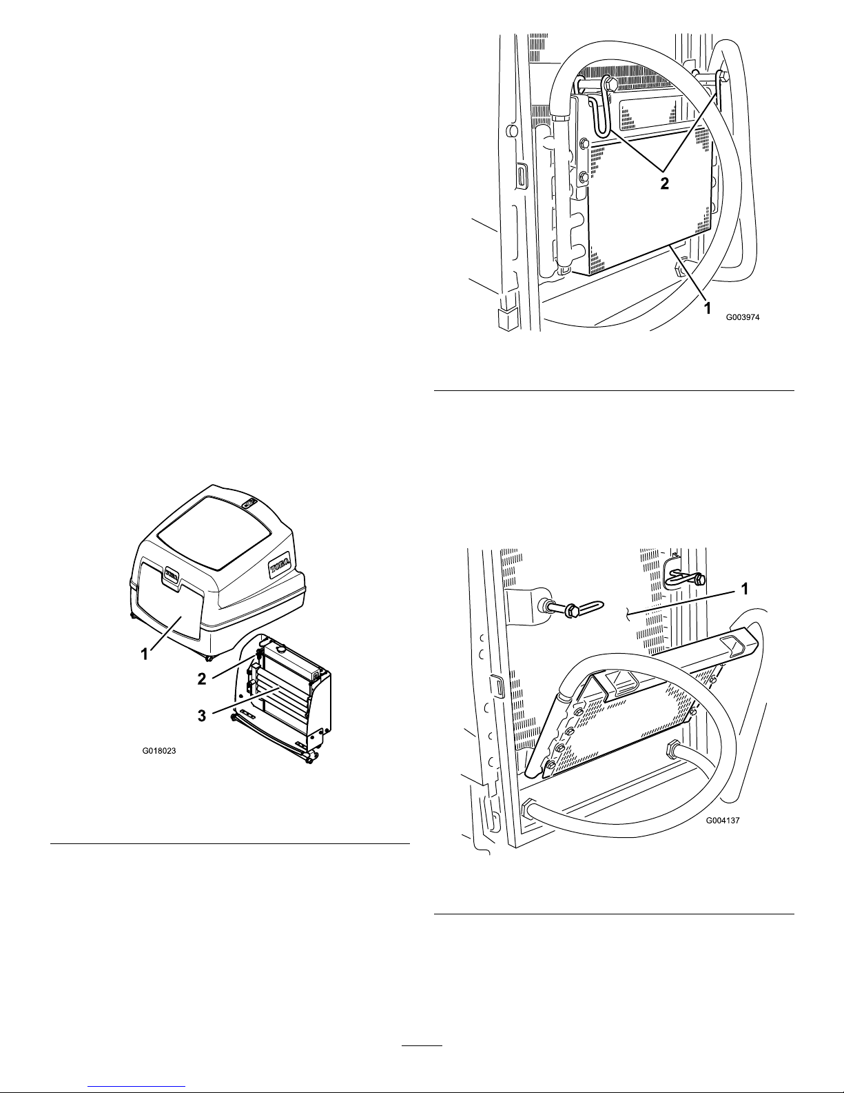
CoolingSystem
Maintenance
RemovingDebrisfromthe
CoolingSystem
ServiceInterval:Beforeeachuseordaily
Every100hours
Every2years
Note:Topreventtheenginefromoverheating,theradiator
andoilcoolermustbekeptclean.Normally,checkdailyand,
ifnecessary,cleananydebrisofftheseparts.However,itwill
benecessarytocheckandcleanmorefrequentlyinextremely
dustyanddirtyconditions.
1.Parkthemachineonalevelsurface,stoptheengine,
settheparkingbrakeandremovethekeyfromthe
ignitionswitch.
2.Cleantheradiatorscreen.
3.Thoroughlycleanalldebrisoutoftheenginearea.
4.Releasethelatchandopentheenginecover(Figure57).
2
3
1
G018023
Figure57
1.Enginecover
3.Oilcooler
2.Oilcoolerreleaseclip
5.Cleanthescreenthoroughlywithcompressedair.
6.Pivotthelatchinwardtoreleasetheoilcooler
(Figure58).
Figure58
1.Oilcooler2.Oilcoolerlatch
7.Workingfromthefansideoftheradiator,blowout
debriswithlowpressure(50psi)compressedair(do
notusewater).Repeatthestepfromthefrontofthe
radiatorandagainfromthefanside.Thoroughlyclean
bothsidesoftheoilcooler.Aftertheradiatorandoil
coolersarethoroughlycleaned,cleanoutanydebris
thatmayhavecollectedonotherpartsofthemachine
(Figure59)withcompressedair.
Figure59
1.Radiator
8.Pivottheoilcoolerbackintopositionandsecurethe
latch.
9.Closetheenginecoverandsecurethelatch.
43
Page 44
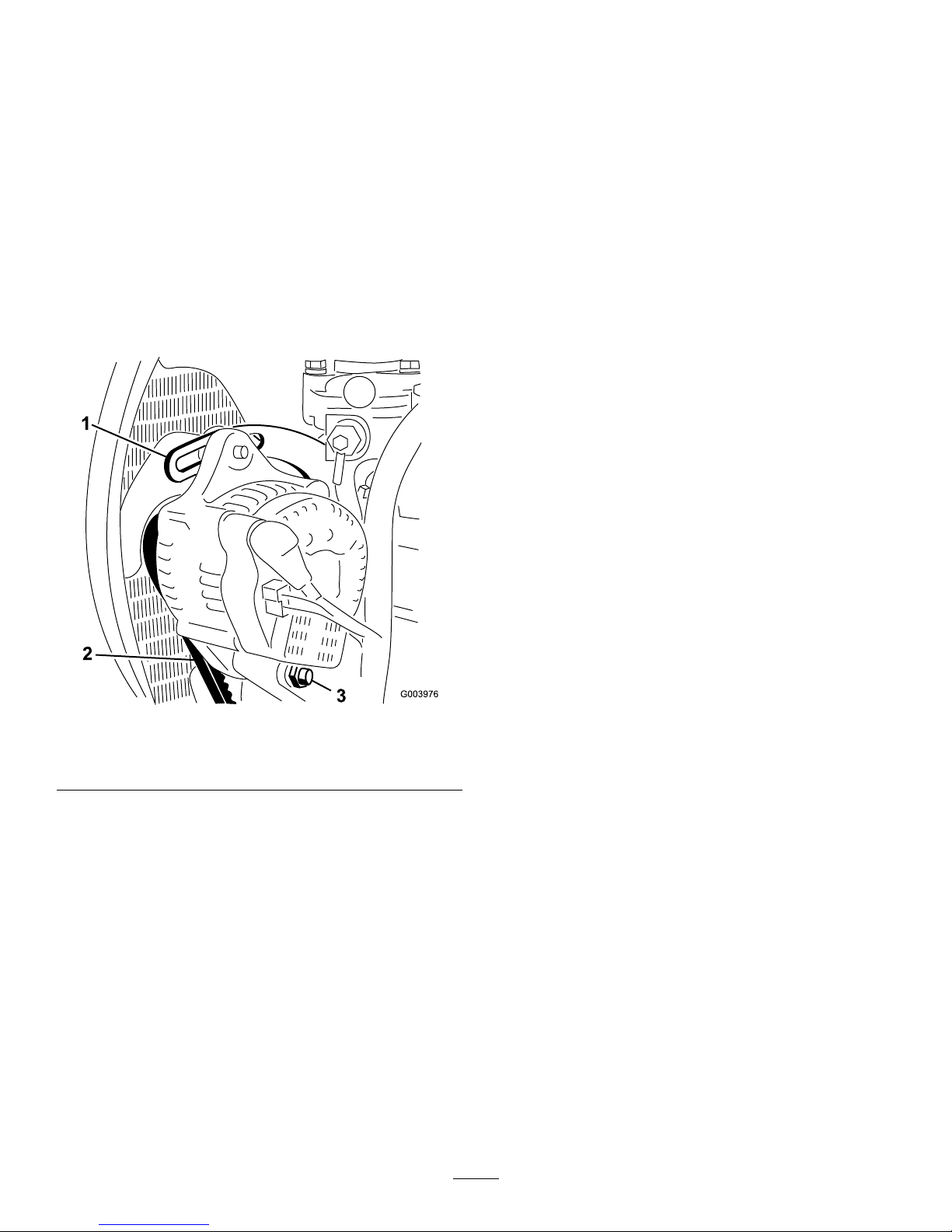
BeltMaintenance
Checktheconditionandtensionofthealternatorbeltafter
therstdayofoperationandevery100operatinghours
thereafter.
TensioningtheAlternatorBelt
ServiceInterval:Aftertherst8hours
Every100hours
1.Openthehood.
2.Checkthetensionofthealternatorbeltbypressing
it(Figure60)midwaybetweenthealternatorandthe
crankshaftpulleyswith10kg(22lb)offorce.
Figure60
1.Brace3.Pivotbolt
2.Alternatorbelt
Thebeltshoulddeect11mm(7/16inch).Ifthe
deectionisincorrect,proceedtostep3Ifcorrect,
continueoperation.
3.Loosentheboltsecuringthebracetotheengine
(Figure60),theboltsecuringthealternatortothebrace
andthepivotbolt.
4.Insertaprybarbetweenthealternatorandtheengine
andpryoutonthealternator.
5.Whenyouachievethepropertension,tighten
thealternator,braceandpivotboltstosecurethe
adjustment.
ControlsSystem
Maintenance
CheckingtheForward/Reverse
TravelPedalAction
Withtheengineswitchedoff,operatetheforwardandreverse
travelpedalsthroughthefullrangeofarticulationandensure
thatthemechanismreturnsfreelytotheneutralposition.
CheckingtheOperator
PresenceSeatSwitch
ServiceInterval:Beforeeachuseordaily
1.Sitontheoperatorseatandstarttheengine.
2.Lowerthecutterheadstotheground.
3.Engagethecutterdriveintheforwarddirection.
4.Risefromtheoperatorseatandcheckthatthecutting
cylinderscometoastopafteraninitial0.5to1second
delay.
5.Repeattheprocedurewiththecuttingcylinders
runninginreverse.
CheckingtheCutterDrive
InterlockSwitch
1.Stopthemowerengine.
2.Operatethecutterdriveswitchtotheoffpositionand
turntheignitionkeytopositionI.Thecutterheads
driveswitchindicatorlightshouldnotilluminate.
3.Operatetheswitchtotheforwardposition.The
indicatorlightshouldilluminateandtheengineshould
notstartwhentheignitionkeyisturned.Repeatfor
thereverseposition.
CheckingtheParkingBrake
InterlockSwitch
1.Stoptheengine.
2.Engagetheparkingbrake.
3.TurntheignitionkeytopositionI.Theparkingbrake
indicatorlightshouldilluminate.
4.Disengagetheparkingbrake.Theindicatorlight
shouldgooutandtheengineshouldnotstartwhen
theignitionkeyisturned.
5.Settheparkingbrake,sitontheoperatorseat,andstart
theengine.
6.Releasetheparkingbrake.
7.Risefromtheoperatorseatandcheckthattheengine
stops.
44
Page 45

CheckingtheTransmission
NeutralInterlockSwitch
1.Stopthemowerengine.
2.Removeyourfootfromtheforward/reversetravel
pedals.
3.TurntheignitionkeytopositionIandthetransmission
neutralindicatorlightshouldilluminate.
4.Applylightpressuretothetravelpedalsinaforward
andreversedirectiontocheckthattheindicatorlight
turnsoff.
Note:Takeextremecaretoensurethattheareaaroundthe
mowerisclearbeforecheckingthattheenginewillnotstart
underthiscondition.
HydraulicSystem
Maintenance
WARNING
Hydraulicuidescapingunderpressurecan
penetrateskinandcauseinjury.
•Makesureallhydraulicuidhosesandlinesare
ingoodconditionandallhydraulicconnections
andttingsaretightbeforeapplyingpressureto
thehydraulicsystem.
•Keepyourbodyandhandsawayfrompin
holeleaksornozzlesthatejecthighpressure
hydraulicuid.
•Usecardboardorpapertondhydraulicleaks.
•Safelyrelieveallpressureinthehydraulicsystem
beforeperforminganyworkonthehydraulic
system.
•Getimmediatemedicalhelpifuidisinjected
intoskin.
ServicingtheHydraulic
System
ServiceInterval:Every500hours
Note:Keepwaterawayfromelectricalcomponents.Usea
dryclothorbrushtocleansuchareas.
Thisprocedureisbestcarriedoutwhenthehydraulicoilis
warm(nothot).Lowerthecutterheadstothegroundand
drainthehydraulicsystem.
1.Removetheoiltankllerangetogainaccesstothe
suctionstrainer.
2.Unscrewandremovethestrainerandcleanwith
parafnorpetrolbeforeinstalling.
3.Installthereturnlineoillterelement.
4.Installthetransmissionoillterelement.
5.Fillthehydraulictankwithfreshcleanhydraulicoilof
therecommendedgrade.
6.Runthemachineandoperateallhydraulicsystemsuntil
thehydraulicoiliswarm.
7.Checktheoillevelandtopupasnecessarytotheupper
markonthesightlevelgauge.
45
Page 46

3
2
1
G014452
Figure61
1.Oil-tankllercap
3.Fillerstrainer
2.Suctionstrainer
CheckingtheHydraulicOil
OverheatWarningSystem
ServiceInterval:Every500hours
1
g022285
2
Figure62
1.Temperatureswitch2.Hydraulic-oiltank
1.TurntheignitionkeytotheignitiononpositionI.
2.Disconnectthered/yellowwireterminalfromthe
hydraulictanktemperatureswitch.
3.Touchthemetalterminalofthewireontoasuitable
earthpoint,ensuringthatthemetalsurfacesmake
goodcontact.
Thehornwillsoundandthehydraulicoiltemperature
warninglightwillilluminatetoconrmcorrectoperation.If
necessary,makerepairsbeforeoperatingthemower.
CheckingtheHydraulicLines
andHoses
Daily,checkhydrauliclinesandhosesforleaks,kinked
lines,loosemountingsupports,wear,loosettings,weather
deterioration,andchemicaldeterioration.Makeallnecessary
repairsbeforeoperating.
46
Page 47

CutterheadsSystem
Maintenance
BackLappingtheCutterheads
WARNING
Contactwiththecutterheadsorothermovingparts
canresultinpersonalinjury.
•Keepngers,hands,andclothingawayfromthe
cutterheadsorothermovingparts.
•Neverattempttoturnthecutterheadsbyhand
orfootwhiletheengineisrunning.
Thisprocessisrecommendedforrestoringthesharpcutting
edgestocylindersandbottombladeswhichareessentialfor
goodqualitygrasscutting.
Thisprocesscanonlydealwithasmallamountofmetal
removaltorestorethecuttingedges.Ifthebladeedgesare
seriouslywornordamageditwillbenecessarytoremovethe
componentpartsandhavethemgroundagain.
1.Ensurethatthemowerengineisoffandthatthe
parkingbrakeisset.
2.Adjustthecuttingcylinderstothebottombladesto
obtaineetingcontact.
3.Applyamedium-gradedetergent-basedcarborundum
pastetothecuttingedgesofthecylinderswitha
long-handledbrush.
80-gradecarborundumpaste
Partnumber
0.45kg(1lb)
63-07-088
11.25kg(25lb)
63-07-086
G014445
Figure63
4.Sitontheoperatorseat,startthemowerengine,and
settheenginespeedatidle.
WARNING
Ifyoutouchthecutterheadswhentheengine
isrunning,youcouldbeseriouslyinjured.
•Ensurethattheareasurroundingthe
cutterheadsisclearofpeople.
•Keephandsandfeetclearofthecutting
cylindersduringtheperiodwhenthe
mowerengineisrunning.
5.Operatethecutterheadsdriveswitchtothe
reverse/backlappositionforaperiodoftimeand
listentothegrindingaction.
6.Operatethecutterheadsdriveswitchtotheoffposition
andswitchoffthemowerenginewhenthegrinding
actionhasstopped.
7.Thoroughlycleanthebladeedgesandadjustthecutting
cylinderstothebottomblades.
8.Checkthatathinpieceofpapercanbecutcleanlyat
allpointsalongthecuttingedgeswhilerotatingthe
cylindersbyhand.
9.Iffurtherbacklappingisnecessaryrepeatsteps2
through8.
10.Thoroughlyremoveandwashoffalltracesofthe
carborundumpastefromthecylindersandbottom
blades.
47
Page 48

GrindingtheCutterheads
Itwillbenecessarytocarryoutagrindingoperationto
correctcylinderspiraledgesorbottombladeedgeswhich
havebecomeexcessivelyroundedordistorted.Bottom
bladeswhicharenearingtheendoftheirwearlifeshouldbe
replaced.Thenewbladesshouldbegroundontheirholders
priortotting.Whengrindingoperationsarenecessaryitis
essentialthatboththecylindersandthebottombladesare
groundatthesametime.Theonlyexceptiontothisruleis
whenanewcylinderistted,inwhichcaseitisonlynecessary
togrindthebottomblade.Allsuchgrindingoperations
shouldbecarriedoutbyyourauthorizeddealeronaquality,
well-maintainedcylinder/bottom-bladegrindingmachine
RaisingTheMowerOffThe
Ground
WARNING
Ifyougounderthemachinewhiletheengineis
running,youcouldbeseriouslyinjuredorkilled.
•Nevercrawlunderthemachinewhiletheengine
isrunning.
•Neverstarttheenginewhilesomeoneisunder
themachine.
Important:Beforeraisingthemowerensurethatthe
liftingdevicetobeusedisingoodconditionandcapable
ofsupportingtheweightofthemowersecurely.
Minimumliftcapacity:2000kg(4409lb)
1.Parkthemoweronlevelground.
2.Settheparkingbrake.
3.Turntheengineswitchtooffandremovetheignition
key.
4.Ensurethegroundundertheliftingdeviceisleveland
rm.
5.Alignandensuretheliftingdeviceissecureagainst
oneofthemowersliftingpoints;refertoLocatingthe
JackingPoints(page29).
6.Ifraisingthefrontofthemower,chocktherearwheels
topreventthemowerfromrollingaway .
Note:Theparkingbrakeoperatesonlyonthefront
wheels.
DisposingofWaste
Engineoil,batteries,hydraulicoil,andenginecoolantare
pollutantstotheenvironment.Disposeoftheseaccordingto
yourlocalregulations.
Whendisposingofhazardouswasteproducts,takethemtoan
authorizeddisposalsite.Wasteproductsmustnotbeallowed
tocontaminatesurfacewater,drains,orsewagesystems.
Important:Disposeofhazardoussubstancescorrectly.
Donotdisposeofbatterieswithaseparatecollection
markintogeneralwaste.
Whendisposingofhazardouswasteproducts,takethem
toanauthorizeddisposalsite.
48
Page 49

Storage
PreparingtheTractionUnit
1.Thoroughlycleanthetractionunit,cuttingunits,and
engine.
2.Checkthetirepressure.RefertoCheckingtheTire
Pressure(page23).
3.Checkallfastenersforloosenessandtightenthemas
necessary.
4.Greaseallgreasettingsandpivotpoints.Wipeup
anyexcesslubricant.
5.Lightlysandandusetouch-uppaintonpaintedareas
thatarescratched,chipped,orrusted.Repairanydents
inthemetalbody.
6.Servicethebatteryandcablesasfollows:
A.Removethebatteryterminalsfromthebattery
posts.
B.Cleanthebattery,terminals,andpostswithawire
brushandbakingsodasolution.
C.Coatthecableterminalsandbatterypostswith
Grafo112Xskin-overgrease(Toropart505-47)
orpetroleumjellytopreventcorrosion.
D.Slowlyrechargethebatteryevery60daysfor24
hourstopreventleadsulfationofthebattery.
PreparingtheEngine
1.Draintheengineoilfromtheoilpanandreplacethe
drainplug.
2.Removeanddiscardtheoillter.Installanewoillter.
3.Relltheoilpanwithdesignatedquantityofmotoroil.
4.Starttheengineandrunitatidlespeedfor
approximately2minutes.
5.Stoptheengine.
6.Thoroughlydrainallfuelfromthefueltank,lines,and
thefuellter/waterseparatorassembly.
7.Flushthefueltankwithfresh,cleandieselfuel.
8.Secureallfuelsystemttings.
9.Thoroughlycleanandservicetheaircleanerassembly.
10.Sealtheair-cleanerinletandtheexhaustoutletwith
weatherprooftape.
11.Checktheantifreezeprotectionandaddantifreezeas
neededfortheexpectedminimumtemperatureinyour
area.
49
Page 50

Troubleshooting
Problem
PossibleCauseCorrectiveAction
1.Y ouareturningtootightly .1.Increasetheturningradius
2.Themachineslidessidewayswhen
travellingacrossthefaceofaslope.
2.Mowup/downtheslope.
3.Thereisnogroundcontactononeend
ofthecutterbecauseofpoorlyrouted
hosesorwronglypositionedhydraulic
adaptors.
3.Correctthehoseroutingortheposition
ofthehydraulicadaptors.
4.Thereisnogroundcontactonone
endofthecutterbecauseapivotpin
isseizing.
4.Releaseandgreasethepivotpoints.
Thereareareasofuncutgrassatthe
overlapbetweencuttingcylinders.
5.Thereisnogroundcontactononeend
ofthecutterbecauseofgrassbuildup
underthecutterhead.
5.Clearthegrassbuildup.
1.Theforwardspeedistoohigh.1.Reduceforwardspeed.
2.Thecylinderspeedistooslow.2.Increasethemowerenginespeed.
Therearefull-widthridgelinesinthecut
acrossthedirectionoftravel.
3.Theheightofcutistoolow.3.Raisetheheightofcut.
Thereareridgelinesinthecutgrass,
acrossthedirectionoftravel,overthe
cuttingwidthofonecylinder.
1.Acylinderisrunningslow .
1.Checkthecylinderspeed;consultyour
authorizeddistributor.
1.Thereisaninconsistentheightofcut
settingononecylinder.
1.Checkandadjusttheheightofcut
setting.
2.Theraise/lowerpositioncontrolisnot
intheoatposition.
2.Setthepositioncontroltotheoat
position.
3.Thereisnogroundcontactononeend
ofthecutterbecauseofpoorlyrouted
hosesorwronglypositionedhydraulic
adaptors.
3.Correctthehoseroutingandthe
positionofthehydraulicadaptors.
4.Thereisnogroundcontactonone
endofthecutterbecauseofpivotpins
seizing.
4.Releaseandgreasethepivotpoints.
Thereisastepinthecutgrassheight
atthepointofoverlapbetweencutting
cylinders.
5.Thereisnogroundcontactononeend
ofthecutterbecauseofgrassbuildup
underthecutterhead
5.Removethegrassbuildup.
1.Acuttingcylinderispartiallyoutof
contactwiththebottomblade.
1.Adjustthe
cutting-cylinder-to-bottom-blade
contact.
2.Acuttingcylinderisinheavycontact
withthebottomblade.
2.Adjustthe
cutting-cylinder-to-bottom-blade
contact.
3.Theheightofcutistoohigh.3.Lowertheheightofcutsetting.
Therearesomeuncutorpoorlycut
strandsofgrass.
4.Thecuttingedgesofthecutting
cylinders/bottombladesarerounded.
4.Backlaporgrindtheedges.
50
Page 51

Problem
PossibleCauseCorrectiveAction
1.Thereistramliningofthecutting
edgesduetoheavycontactcausedby
poorcutting-cylinder-to-bottom-blade
adjustment.
1.Backlaporgrindtheedges.
2.Thebottombladeisincontactwiththe
ground.
2.Raisetheheightofcut.
3.Thebottombladehasanose-down
attitude.
3.Adjustthecutterheadtopositionthe
bottombladeparalleltotheground.
4.Thecutterheadsarebouncing.
4.Reducetheforwardspeedandreduce
theweighttransfer.
5.Thereareworncylinder
bearings/bearinghousingpivots.
5.Replaceanywornparts.
Therearelinesofuncutorbadlycutgrass
inthedirectionoftravel.
6.Thereareloosecomponentsinthe
cutterhead.
6.Checkandtightencomponentsas
necessary.
1.Theundulationsaretoosevereforthe
heightofcutsetting.
1.Useoatingcutterheads. Thereisscalpingoftheturf.
2.Theheightofcutistoolow.2.Raisetheheightofcut.
1.Thebottombladeisinheavycontact
withtheground.
1.Raisetheheightofcut.
2.Thecuttingedgesofthecutting
cylinderand/orbottombladeare
rounded.
2.Backlaporgrindtheedges.
3.Thecylinderisinheavycontactwith
thebottomblade.
3.Adjustthe
cutting-cylinder-to-bottom-blade
contact.
4.Thereisadamagedcuttingcylinderor
bottomblade.
4.Grindorreplacepartsasnecessary.
Thereisexcessivebottombladewear .
5.Thereareexcessivelyabrasiveground
conditions.
5.Raisetheheightofcut.
1.Thetransmissionneutralinterlock
switchisnotenergized.
1.Removeyourfootfromthe
forward/reversepedalsorcheck
thesettingofthetransmissionneutral
interlockswitch.
2.Theparkingbrakeinterlockswitchis
notenergized.
2.Movetheparkingbrakeswitchtothe
Onposition.
3.Thecutterheaddriveinterlockswitchis
notenergized.
3.MovethecutterswitchtotheOff
position.
Theenginedoesnotstartwiththeignition
key.
4.Thereisamalfunctioningelectrical
connection.
4.Locateandcorrectthefaultinthe
electricalsystem.
1.Aterminalconnectionislooseor
corroded.
1.Cleanandtightentheterminal
connections.Chargethebattery.
2.Thealternatorbeltislooseorworn.2.Adjustthetensionorreplacethebelt;
refertoengineoperator’smanual.
3.Thebatteryisdischarged.
3.Chargeorreplacethebattery.
Thebatteryhasnopower.
4.Thereisanelectricalshortcircuit.
4.Locatetheshortcircuitandxit.
1.Thereisablockedscreen.
1.Cleanthescreen.
2.Theoilcoolernsaredirty/blocked.2.Cleanthens.
3.Theengineradiatorisdirty/blocked.3.Cleantheradiator .
4.Thereliefvalvesettingislow .4.Havethereliefvalvepressurechecked.
Consultyourauthorizeddistributor.
5.Theoillevelislow.5.Fillthereservoirtothecorrectlevel.
6.Thebrakesareengaged.6.Disengagethebrakes.
7.Thecuttingcylinderstightonthe
bottomblades.
7.Adjustthesettings.
Thehydraulicoilsystemisoverheating.
8.Thereisamalfunctioningfanorfan
drive.
8.Checkthefanoperationandservice
itasrequired.
51
Page 52

Problem
PossibleCauseCorrectiveAction
1.Thereisamalfunctioningwheelmotor
brakeassembly.
1.Consultyourauthorizeddistributor.
Thebrakesystemdoesnotoperate
correctly.
2.Thebrakediscsareworn.2.Replacethebrakediscs;consultyour
authorizeddistributor.
1.Thesteeringvalveismalfunctioning.1.Serviceorreplacethesteeringvalve.
2.Ahydrauliccylinderismalfunctioning.2.Serviceorreplacethehydraulic
cylinder.
Thereisalackofsteering.
3.Asteeringhoseisdamaged.3.Replacethehose.
1.Theparkingbrakeisengaged.1.Releasetheparkingbrake.
2.Theoillevelislow.2.Fillthereservoirtothecorrectlevel.
3.Thereservoirhasthewrongkindofoil.3.Drainthereservoirandllitwiththe
correctoil.
4.Thedrivepedallinkageisdamaged.
4.Checkthelinkageandreplaceany
damagedorwornparts.
5.Thetransmissionpumpisdamaged.5.Havethetransmissionpump
overhauledbyyourauthorized
distributor.
6.Thetransmissionbypassvalveisopen.
6.Closethebypassvalve.
Thereisnomachinemovementinforward
orreverse.
7.Thereisabrokendrivecoupling.7.Replacethedrivecoupling.
Themachinecreepsforwardorbackward
inneutral.
1.Thetransmissionneutraladjustmentis
setincorrectly.
1.Adjustthetransmissionneutrallinkage
setting.
1.Apumpismalfunctioning.1.Identifythenoisypumpandserviceor
replaceit.
2.Amotorismalfunctioning.2.Identifythenoisymotorandserviceor
replaceit.
3.Airisleakingintothesystem.
3.Tightenorreplacethehydraulicttings,
particularlyinthesuctionlines.
4.Asuctionstrainerisblockedor
damaged.
4.Cleanandreplacethesuctionstrainer
orrenewitasnecessary.
5.Theoilhasexcessiveviscositydueto
coldconditions.
5.Allowthesystemtowarmup.
6.Thereliefvalvesettingislow .6.Havethereliefvalvepressurechecked.
Consultyourauthorizeddistributor.
Thereisexcessivenoiseinthehydraulic
system.
7.Thehydraulicoillevelislow.7.Fillthehydraulicoilreservoirtothe
correctlevel.
1.Apumpormotorisworn.1.Replacepartsasnecessary.
2.Thehydraulicoillevelislow.2.Fillhydraulicoiltanktocorrectlevel
3.Theoilinthehydraulicsystemhasthe
wrongviscosity.
3.Replacetheoilinthehydraulictank
withthecorrectviscosity-gradeoil;
refertotheSpecicationssection.
4.Theoil-lterelementisblocked.4.Changethelterelement.
5.Thepressurereliefvalveis
malfunctioning.
5.Havethereliefvalvecleanedand
pressurechecked.Consultyour
authorizeddistributor.
6.Thesystemisoverheating.
6.Checkthecylinder-to-bottom-blade
adjustment.Reducetheworkrate
(increasetheheightofcutorreduce
theforwardspeed).
Afteraninitialperiodofsatisfactory
operation,themachinelosespower .
7.Thereareleaksonthesuctionhose.
7.Checkandtightenthettings.Replace
thehoseifnecessary.
1.Thereisahighspotonthecylinderor
thebottombladeduetocontactwitha
foreignobject.
1.Removethehighspotwithastoneand
backlaptorestorethecuttingedges.
Severedamagewillrequiregrinding.
Acylinder‘knocks’whilerotating.
2.Thecylinderbearingsareworn.2.Replacethebearingsasnecessary.
52
Page 53

Problem
PossibleCauseCorrectiveAction
1.Acuttingcylinderbearingisseized.1.Replacethebearingsasnecessary.
2.Amotorwithincorrectrotationwas
installed.
2.Checkthemotorandreplaceitif
necessary.
3.Themotorintegralcheckvalveis
jammedopen.
3.Havethecheckvalvecleanedand
checked.
4.Thecuttingcylinderistightonthe
bottomblade.
4.Adjustthesetting.
Onecylinderrotatesslowly.
5.Themotorisworn.5.Replacethemotor.
1.Thereisaliftcylindersealfailure.
1.Replacetheseals.
2.Thepressurereliefvalveisjammed
openorwronglyset.
2.Havethereliefvalvepressurechecked.
Consultyourauthorizeddistributor.
3.Thereisamalfunctioningcontrolvalve.3.Overhaulthecontrolvalve.
Acutterheadfailstoliftoutofwork.
4.Thereismechanicalblockage.4.Removetheblockage.
1.Thehoseroutingortheorientationof
thehydraulicttingsisincorrect.
1.Movethecutterheadsthroughoutthe
extremesofmovementandobserve
anytightnessinthehoses.Correctly
routethehosesandorientatethe
ttingsasnecessary .
2.Thepivotpointsaretootight.2.Releaseandgreasethepivotpointas
necessary.
3.Themowerisbeingoperatedinthe
‘hold’position.
3.Movethepositioncontrolswitchto
‘down/oat’position.
Thecutterheadsdonotfollowthecontours
oftheground.
4.Theweighttransferissettoohigh.4.Reducetheweighttransfer.
1.Theseatsensorswitchis
malfunctioning.
1.Checkthemechanicalandelectrical
operationoftheswitch.
2.Thehydraulic-oillevelislow.2.Fillthehydraulic-oilreservoirtothe
correctlevel.
3.Adriveshaftissheared.3.Checkthemotorandcylinder
driveshaftsandreplacethemif
necessary.
4.Thepressurereliefvalveisjammed
openorwronglyset.
4.Havethereliefvalvepressurechecked.
Consultyourauthorizeddealer .
5.Acuttingcylinderisjammed.
5.Clearanyjamsasnecessary.
6.Acuttingcylinderistightonthebottom
blade.
6.Adjustthesetting.
7.Acutterheadcontrolvalveisinthe
‘off’position,causedbymalfunctioning
controlvalve.
7.Overhaulthecontrolvalve.
8.Acutterheadcontrolvalveisinthe‘off’
position,causedbyanelectricalfault.
8.Havetheelectricalsystemcheckedfor
anelectricalfault.
Thecutterheadsfailtostartupwhen
loweredintowork.
9.Theliftarmproximityswitchis
incorrectlyset.
9.Checkandadjusttheproximityswitch.
1.Thehosesareconnectedwrongly.
1.Checkthehydrauliccircuitandconnect
thehosescorrectly .
Thecylindersrotateinthewrongdirection.
2.Thecutterheaddriveswitchis
connectedwrongly.
2.Checktheelectricalconnectionsofthe
switch.
53
Page 54

Notes:
54
Page 55

InternationalDistributorList
Distributor:
Country:
PhoneNumber:Distributor:
Country:
Phone
Number:
AtlantisSuveSulamaSisstemleriLt
Turkey902163448674
MaquiverS.A.Colombia
5712364079
BalamaPrimaEngineeringEquip.HongKong85221552163
MaruyamaMfg.Co.Inc.
Japan81332522285
B-RayCorporation
Korea82325512076
AgrolancKft
Hungary3627539640
CascoSalesCompany
PuertoRico7877888383
Mountelda.s.CzechRepublic
420255704
220
CeresS.A.CostaRica
5062391138
MunditolS.A.
Argentina541 14821
9999
CSSCTurfEquipment(pvt)Ltd.SriLanka
94112746100
OslingerTurfEquipmentSA
Ecuador59342396970
CyrilJohnston&Co.
NorthernIreland442890813121
OyHakoGroundandGarden
Ab
Finland35898700733
EquiverMexico525553995444ParklandProductsLtd.NewZealand6433493760
FemcoS.A.Guatemala
5024423277
PratoVerdeS.p.A.
Italy390499128
128
G.Y .K.CompanyLtd.
Japan81726325861
Prochaska&Cie
Austria4312785100
GeomechanikiofAthensGreece
30109350054
RTCohen2004Ltd.
Israel97298617979
GuandongGoldenStarChina
862087651338Riversa
Spain
34952837500
HakoGroundandGardenSweden
4635100000
ScSvendCarlsenA/S
Denmark4566109200
HakoGroundandGarden
Norway4722907760
SolvertS.A.S.
France331308177
00
HayterLimited(U.K.)
UnitedKingdom441279723444
SpyprosStavrinidesLimitedCyprus
35722434131
HydroturfInt.CoDubai
UnitedArabEmirates97143479479
SurgeSystemsIndiaLimited
India911292299901
HydroturfEgyptLLC
Egypt2025194308T-MarktLogisticsLtd.Hungary3626525500
IrriamcPortugal351212388260T oroAustraliaAustralia61395807355
IrrigationProductsInt'lPvtLtd.India0091442449
4387
ToroEuropeNVBelgium3214562960
JeanHeybroekb.v.Netherlands3130639461 1
EuropeanPrivacyNotice
TheInformationToroCollects
ToroWarrantyCompany(T oro)respectsyourprivacy .Inordertoprocessyourwarrantyclaimandcontactyouintheeventofaproductrecall,weaskyou
tosharecertainpersonalinformationwithus,eitherdirectlyorthroughyourlocalT orocompanyordealer .
TheT orowarrantysystemishostedonserverslocatedwithintheUnitedStateswhereprivacylawmaynotprovidethesameprotectionasapplies
inyourcountry.
BYSHARINGYOURPERSONALINFORMATIONWITHUS,YOUARECONSENTINGTOTHEPROCESSINGOFYOURPERSONALINFORMATION
ASDESCRIBEDINTHISPRIV ACYNOTICE.
TheWayT oroUsesInformation
Toromayuseyourpersonalinformationtoprocesswarrantyclaims,tocontactyouintheeventofaproductrecallandforanyotherpurposewhichwetell
youabout.ToromayshareyourinformationwithT oro'safliates,dealersorotherbusinesspartnersinconnectionwithanyoftheseactivities.Wewillnot
sellyourpersonalinformationtoanyothercompany.Wereservetherighttodisclosepersonalinformationinordertocomplywithapplicablelawsand
withrequestsbytheappropriateauthorities,tooperateoursystemsproperlyorforourownprotectionorthatofotherusers.
RetentionofyourPersonalInformation
Wewillkeepyourpersonalinformationaslongasweneeditforthepurposesforwhichitwasoriginallycollectedorforotherlegitimatepurposes
(suchasregulatorycompliance),orasrequiredbyapplicablelaw .
Toro'sCommitmenttoSecurityofY ourPersonalInformation
Wetakereasonableprecautionsinordertoprotectthesecurityofyourpersonalinformation.Wealsotakestepstomaintaintheaccuracyandcurrent
statusofpersonalinformation.
AccessandCorrectionofyourPersonalInformation
Ifyouwouldliketorevieworcorrectyourpersonalinformation,pleasecontactusbyemailatlegal@toro.com.
AustralianConsumerLaw
AustraliancustomerswillnddetailsrelatingtotheAustralianConsumerLaweitherinsidetheboxoratyourlocalT oroDealer.
374-0269RevG
Page 56

TheToroT otalCoverageGuarantee
ALimitedWarranty
ConditionsandProductsCovered
TheToro
®
Companyanditsafliate,T oroWarrantyCompany ,pursuant
toanagreementbetweenthem,jointlywarrantyourT oroCommercial
product(“Product”)tobefreefromdefectsinmaterialsorworkmanship
fortwoyearsor1500operationalhours*,whicheveroccursrst.This
warrantyisapplicabletoallproductswiththeexceptionofAerators
(refertoseparatewarrantystatementsfortheseproducts).Wherea
warrantableconditionexists,wewillrepairtheProductatnocosttoyou
includingdiagnostics,labor,parts,andtransportation.Thiswarranty
beginsonthedatetheProductisdeliveredtotheoriginalretailpurchaser.
*Productequippedwithanhourmeter.
InstructionsforObtainingWarrantyService
YouareresponsiblefornotifyingtheCommercialProductsDistributoror
AuthorizedCommercialProductsDealerfromwhomyoupurchasedthe
Productassoonasyoubelieveawarrantableconditionexists.Ifyouneed
helplocatingaCommercialProductsDistributororAuthorizedDealer,or
ifyouhavequestionsregardingyourwarrantyrightsorresponsibilities,
youmaycontactusat:
CommercialProductsServiceDepartment
ToroWarrantyCompany
811 1LyndaleAvenueSouth
Bloomington,MN55420-1196
E-mail:commercial.warranty@toro.com
OwnerResponsibilities
AstheProductowner,youareresponsibleforrequiredmaintenanceand
adjustmentsstatedinyourOperator’sManual.Failuretoperformrequired
maintenanceandadjustmentscanbegroundsfordisallowingawarranty
claim.
ItemsandConditionsNotCovered
Notallproductfailuresormalfunctionsthatoccurduringthewarranty
periodaredefectsinmaterialsorworkmanship.Thiswarrantydoesnot
coverthefollowing:
•Productfailureswhichresultfromtheuseofnon-T ororeplacement
parts,orfrominstallationanduseofadd-on,ormodiednon-Toro
brandedaccessoriesandproducts.Aseparatewarrantymaybe
providedbythemanufactureroftheseitems.
•Productfailureswhichresultfromfailuretoperformrecommended
maintenanceand/oradjustments.Failuretoproperlymaintainyour
ToroproductpertheRecommendedMaintenancelistedinthe
Operator’sManualcanresultinclaimsforwarrantybeingdenied.
•ProductfailureswhichresultfromoperatingtheProductinanabusive,
negligentorrecklessmanner.
•Partssubjecttoconsumptionthroughuseunlessfoundtobedefective.
Examplesofpartswhichareconsumed,orusedup,duringnormal
Productoperationinclude,butarenotlimitedto,brakespadsand
linings,clutchlinings,blades,reels,bedknives,tines,sparkplugs,
castorwheels,tires,lters,belts,andcertainsprayercomponents
suchasdiaphragms,nozzles,andcheckvalves,etc.
•Failurescausedbyoutsideinuence.Itemsconsideredtobeoutside
inuenceinclude,butarenotlimitedto,weather,storagepractices,
contamination,useofunapprovedcoolants,lubricants,additives,
fertilizers,water,orchemicals,etc.
•Normalnoise,vibration,wearandtear ,anddeterioration.
•Normal“wearandtear”includes,butisnotlimitedto,damagetoseats
duetowearorabrasion,wornpaintedsurfaces,scratcheddecalsor
windows,etc.
Parts
Partsscheduledforreplacementasrequiredmaintenancearewarranted
fortheperiodoftimeuptothescheduledreplacementtimeforthatpart.
Partsreplacedunderthiswarrantyarecoveredforthedurationofthe
originalproductwarrantyandbecomethepropertyofT oro.Torowillmake
thenaldecisionwhethertorepairanyexistingpartorassemblyorreplace
it.T oromayuseremanufacturedpartsforwarrantyrepairs.
NoteRegardingDeepCycleBatteryWarranty:
Deepcyclebatterieshaveaspeciedtotalnumberofkilowatt-hoursthey
candeliverduringtheirlifetime.Operating,recharging,andmaintenance
techniquescanextendorreducetotalbatterylife.Asthebatteriesin
thisproductareconsumed,theamountofusefulworkbetweencharging
intervalswillslowlydecreaseuntilthebatteryiscompletelywornout.
Replacementofwornoutbatteries,duetonormalconsumption,isthe
responsibilityoftheproductowner.Batteryreplacementmayberequired
duringthenormalproductwarrantyperiodatowner’sexpense.
MaintenanceisatOwner’sExpense
Enginetune-up,lubricationcleaningandpolishing,replacementofItems
andConditionsNotCoveredlters,coolant,andcompletingRecommended
MaintenancearesomeofthenormalservicesT oroproductsrequirethat
areattheowner’sexpense.
GeneralConditions
RepairbyanAuthorizedToroDistributororDealerisyoursoleremedy
underthiswarranty.
NeitherTheToroCompanynorToroWarrantyCompanyisliablefor
indirect,incidentalorconsequentialdamagesinconnectionwiththe
useoftheToroProductscoveredbythiswarranty,includingany
costorexpenseofprovidingsubstituteequipmentorserviceduring
reasonableperiodsofmalfunctionornon-usependingcompletion
ofrepairsunderthiswarranty.ExceptfortheEmissionswarranty
referencedbelow,ifapplicable,thereisnootherexpresswarranty .
Allimpliedwarrantiesofmerchantabilityandtnessforusearelimitedtothe
durationofthisexpresswarranty .Somestatesdonotallowexclusionsof
incidentalorconsequentialdamages,orlimitationsonhowlonganimplied
warrantylasts,sotheaboveexclusionsandlimitationsmaynotapplytoyou.
Thiswarrantygivesyouspeciclegalrights,andyoumayalsohaveother
rightswhichvaryfromstatetostate.
CountriesOtherthantheUnitedStatesorCanada
CustomersshouldcontacttheirT oroDistributor(Dealer)toobtainguaranteepoliciesforyourcountry ,province,orstate.Ifforanyreasonyouare
dissatisedwithyourDistributor'sserviceorhavedifcultyobtainingguaranteeinformation,contacttheT oroimporter.Ifallotherremediesfail,you
maycontactusatT oroWarrantyCompany.
374-0277RevA
 Loading...