

Page 1

Part No. 111-4378 Rev A
LT3240 4WD TRIPLE BASE UNIT
Model No: 02740-Serial No. from 310000001
Operator’s Manual
Original Instructions (EN)
Date: 24.09.10
Page 2

Page 3

ATTENTION
THIS SYMBOL MEANS
BE ALERT!
YOUR SAFETY IS INVOLVED
READ THIS MANUAL BEFORE USING THE LT3240 MOWER.
IT IS ESSENTIAL THAT OPERATORS STUDY IT FOR THEIR
OWN SAFETY.
ALL OPERATORS SHOULD SEEK AND OBTAIN PROFESSIONAL AND
PRACTICAL INSTRUCTIONS ON THE SAFE USE OF THE MOWER.
THESE SERVICES ARE AVAILABLE THROUGH TORO APPROVED
COMMERCIAL DEALERS.
Page 4

Page 5

1.5 1.5
CONTENTS Page No.
SAFETY PRECAUTIONS 1.7 - 1.17
Training 1.7
Preparation 1.8
Operation 1.9 - 1.10
Slopes 1.9
Handling and storage of uids 1.11
Maintenance and storage 1.12
Decals 1.13 - 1.17
EC CONFORMITY INFORMATION 1.18 - 1.19
Noise / Vibration levels 1.18
EC Declaration of Conformity 1.19
INTRODUCTION 1.20
SPECIFICATIONS 1.21 - 1.24
Engine 1.21
Transmission system 1.21
Cutterhead drive system 1.22
Cutterhead lift system and steering 1.22
Hydraulic system 1.22
Vehicle specications 1.23
Operator controls 1.23
Instrumentation 1.24
Weight and dimensions 1.24
Recommended lubricants and hydraulic uids 1.24
Cutterhead 1.24
OPERATING THE MOWER 1.25 - 1.43
Safety Notice 1.25
Operator presence controls 1.25
Identication of control panel components 1.26
Braking system 1.27
Throttle control 1.27
Travel 1.27
Transport latches 1.28
Differential lock 1.28
Speed control pedals 1.29
Operator platform latching mechanism 1.29 - 1.30
Adjustable steering column 1.30
Folding the R.O.P.S 1.31
Operator seat 1.32
Warning systems 1.33
Audible warning horn 1.33
Ignition key 1.34
Engine pre-heat indicator light 1.34
CONTENTS
Page 6

1.6 1.6
CONTENTS Page No.
Fuel level gauge 1.34
Hour meter 1.34
Transmission neutral indicator light 1.35
Cutterhead drive switch indicator light 1.35
Parking brake indicator light 1.35
Hydraulic return lter indicator light 1.35
Hydraulic transmission lter indicator light 1.35
Cutterhead position control 1.36
Cutterhead drive engagement 1.36
Weight transfer / traction assistance 1.37
Starting the engine 1.37 - 1.38
Stopping the engine 1.38
Unblocking the cutting cylinders 1.38 - 1.39
Centre cutterhead height of cut correction adjustment 1.39
General operating hints 1.40
Cutterhead general information 1.41
MK3 200mm xed cutterhead 1.42
MK3 254mm xed cutterhead 1.42
MK3 200mm oating cutterhead 1.43
MAINTENANCE 1.44 - 1.60
Maintenance 1.44 - 1.45
Engine 1.46
Running in period 1.46
Running in period - at rst 50 hours 1.46
Daily and before use 1.47 - 1.50
Every 50 hours 1.51 - 1.52
Every 250 hours 1.53
Every 500 hours 1.54 - 1.55
Cutterhead cylinder to bottom blade adjustment 1.56
Cutterhead back lapping 1.57
Cutterhead grinding 1.58
Cutterhead bottom blade replacement 1.58
Raising the mower off the ground 1.58
Towing the mower 1.59 - 1.60
GRASS CUTTING FAULTS 1.61 - 1.62
TROUBLE SHOOTING 1.63 - 1.66
ELECTRICAL CIRCUIT DIAGRAM 1.67 - 1.68
HYDRAULIC CIRCUIT DIAGRAMS 1.69 - 1.71
WARRANTY 1.72
NOTES 1.73 - 1.75
INTERNATIONAL DISTRIBUTION LIST 1.76
CUSTOMER INFORMATION 1.77 - 1.78
CONTENTS
Page 7

1.7 1.7
SAFETY PRECAUTIONS
This manual should be regarded as part of the machine, as it gives essential
information regarding machine safety, operation, maintenance and specications.
READ THIS MANUAL BEFORE USING THE LT3240 MOWER, IT IS
ESSENTIAL THAT OPERATORS STUDY IT FOR THEIR OWN SAFETY.
THE FOLLOWING PRECAUTIONS MUST BE TAKEN TO HELP PREVENT
ACCIDENTS. A CAREFUL OPERATOR WHO USES COMMON SENSE IS THE
SAFEST OPERATOR.
Training
Read the instructions carefully. Be familiar with the controls and the proper use of the equipment. Learn how
to stop the mower quickly in an emergency.
Never allow children or people unfamiliar with these instructions to use the mower. Local regulations may
restrict the age of the operator.
Never mow while people, especially children, or pets are nearby.
Keep in mind that the operator or user is responsible for accidents or hazards occurring to other people or
their property.
Do not carry passengers.
All drivers should seek and obtain professional and practical instruction. Such instruction should
emphasise:
The need for care and concentration when working with this machine.
The need to slow down when making tight turning manoeuvres. Failure to take adequate care can affect
stability leading to loss of control of the machine particularly when operating in transport mode.
Control of a ride-on-machine sliding on a slope will not be regained by application of the parking brake.
The main reasons for loss of control are:
- Insufcient wheel grip.
- Being driven too fast.
- Inadequate braking.
- The type of machine is unsuitable for the task.
- Lack of awareness of the effect of ground conditions, especially slopes.
- Incorrect load distribution.
Page 8

1.8 1.8
SAFETY PRECAUTIONS
Preparation
Check that the machine complies with all applicable regulations, including those in force when used on the
public highway.
While mowing, always wear substantial footwear and long trousers. Do not operate the equipment when
barefoot or wearing open sandals. Eye protection should be worn.
Thoroughly inspect the area where the equipment is to be used and remove all objects which can be thrown
by the machine.
Never operate the machine without rst checking that the operator platform latching mechanism is fully
engaged and in good working order, refer to OPERATOR PLATFORM LATCHING MECHANISM.
Ensure that the cutterheads are fully raised with the latches and safety locks engaged in position before
transporting the mower.
Replace faulty silencers.
Check the condition of the tyres and ensure that they are inated to the correct pressures, refer to
SPECIFICATIONS. This is particularly important if the machine is to be taken on the public highway.
Check that the mower is in good working order, paying particular attention to the brakes and steering. Also
ensure that the forward/reverse speed control pedals move freely to neutral when released.
Before use, always visually inspect to see that the blades, blade bolts and cutting cylinders are not worn or
damaged. Replace worn or damaged components.
Check the mower hydraulic system, particularly the hydraulic hoses, ttings and hose supports. Worn,
crushed or damaged hoses can burst, with risks to health and damage to the machine and surrounding turf
areas.
After refuelling and adding oil to the hydraulic oil tank ensure that the caps are replaced securely.
Check that all linkages, connections and pivot nuts are secure and that wheel nuts are torqued correctly,
refer to SPECIFICATIONS.
Before operating the machine ensure that there are no foreign objects or liquids on the platform or
pedals - ALWAYS KEEP THE OPERATOR PLATFORM CLEAN/CLEAR.
Always make sure that the folding R.O.P.S is secured in its vertical operating position before use.
Page 9

Ground level
16 Degree slope
1.9 1.9
SAFETY PRECAUTIONS
Operation
Do not operate the engine in a conned space where dangerous carbon monoxide fumes can collect.
Mow only in daylight or in good articial light.
Before attempting to start the engine, engage the parking brake, disengage the cutterhead drive system and
ensure that the forward/reverse speed controls are in the neutral position.
Never operate the machine without rst checking that the operator platform latching mechanism is fully
engaged and in good working order, refer to OPERATOR PLATFORM LATCHING MECHANISM.
Slopes
Do not use on a slope of more than 16 degrees. Care should be taken when using the mower on any slope
where ground conditions are such that there may be a risk of the mower rolling over. The requirements of
89/355/EEC, as amended by 95/63/EEC ‘Provision and Use of Work Equipment Directive’ should be
considered.
Stability angles given are maximum gures for a machine equipped with a R.O.P.S and are for guidance only.
Particular conditions such as wet grass or uneven ground may not permit safe operation on the slope limits
stated.
Remember there is no such thing as a ‘safe’ slope. Travel on grass slopes requires particular care. To guard
against overturning or loss of traction when travelling or mowing on a slope:
- Exercise extreme care when changing direction on a slope.
- Do not stop or start suddenly.
- Engage drive slowly.
- Keep machine speed low.
- Avoid tight turns.
- Stay alert for humps, hollows and other hidden hazards.
- Keep away from sharp inclines and steep drops.
- A thorough risk assessment should be carried out by a competent person before travelling or mowing on a
slope.
Never park on a slope.
Fig 1
Page 10

1.10 1.10
SAFETY PRECAUTIONS
Operation continued
Watch out for trafc when crossing or near roadways.
Use extreme caution when reversing.
Disengage the cutterhead drive system before crossing surfaces other than grass.
When using the machine, never direct discharge of material towards bystanders or allow anyone near the
machine while in operation.
Never operate the mower with defective guards, shields or without safety protective devices in place and in
good working order.
Do not change the engine governor settings or overspeed the engine. Operating an engine at excessive speed
may increase the risk of personal injury.
Before leaving the operator’s position:
- Disengage the drive to the cutterheads.
- Lift cutterheads to the transport position and securely lock the safety latches or alternatively lower
cutterheads to the ground.
- Ensure the transmission is in neutral and engage the parking brake.
- Stop the engine and remove the ignition key.
Engage the parking brake, disengage the drive to the cutterheads, stop the engine and remove ignition key:
- Before releasing blockages.
- Before checking, cleaning or working on the mower.
- After striking a foreign object. Inspect the mower for damage and make repairs before restarting and
operating the equipment.
- If the machine starts to vibrate abnormally (check immediately).
- Before refuelling.
- Before making cutterhead adjustments.
Disengage the drive to the cutterheads when transporting or not in use.
Reduce the throttle setting during engine run out.
Never work on the mower when the engine is running.
Always keep feet and hands well away from the cutting cylinders when making adjustments.
Never operate the mower without rst checking that the operator platform is securely latched.
Always wear the seat belt when the folding R.O.P.S is in its vertical operating position.
Never wear the seat belt when the folding R.O.P.S is NOT in its vertical operating position.
Pay particular attention when operating due to the additional weight towards the front of the machine.
Page 11

1.11 1.11
SAFETY PRECAUTIONS
Handling and Storage of Fluids
Hydraulic Oil
- Avoid contact with eyes and prolonged contact with skin.
- Protective goggles should be worn when pouring.
- Use of gloves or barrier cream is recommended.
- Wash hands thoroughly after contact.
- Store under cover, away from heat and sources of ignition.
Diesel Oil
- Avoid skin and eye contact.
- Wear impervious gloves when regular contact is likely and goggles when there is risk of splashing.
- Wash hands thoroughly after contact.
- Store in a cool dry well ventilated place away from heat and sources of ignition, in vessels specically
designed for storing fuel oils.
Lubricating Oil
- Avoid skin and eye contact.
- Wear impervious gloves when regular contact is likely and goggles when there is risk of splashing.
- Wash hands thoroughly after contact.
- Store in a cool dry well ventilated place away from heat and sources of ignition.
Anti- Freeze
- Keep away from heat, sparks, and ames.
- Avoid skin and eye contact and breathing vapors.
- Store in a closed container in a cool dry well ventilated area.
Page 12

1.12 1.12
SAFETY PRECAUTIONS
Maintenance and Storage
Take care when rotating a cutting cylinder as this can cause other cylinders to rotate.
When the machine is to be parked, stored or left unattended, lift the cutterheads to the transport position and
engage the safety locks or lower the cutterheads to the ground.
Keep all nuts, bolts, and screws tight to be sure the equipment is in safe working condition.
Allow the engine to cool before storing in any enclosure.
To reduce the risk of re, keep the engine, silencer, fuel tank and battery compartment free of grass, leaves or
excessive grease.
Frequently check fuel lines and ttings for cracks or leaks and replace if necessary.
Replace worn or damaged parts for safety.
Ensure that all safety decals are properly secured and in good condition.
If the fuel tank has to be drained, this should be done outdoors.
Be careful during adjustment of the machine to prevent entrapment of the ngers between moving blades and
xed parts of the machine.
Never attempt to disconnect any part of the hydraulic system before depressurisation. This may be achieved
by lowering all cutterheads to the ground, stopping the engine and removing the ignition key.
Avoid skin or eye contact with hydraulic or diesel uids. Wear protective clothing.
Leaking uids under pressure can penetrate the skin or eyes, causing serious injury.
Always use a piece of cardboard or paper when searching for leaks.
The LT3240 Mower has been designed and constructed so that, in so far as is reasonably practical,
they meet the safety requirements of the Machinery Directive 2006/42/EC, they will not endanger the
safety and health of those working with them. This is, however, subject to the machine being properly
used and maintained according to the conditions stated in this manual and elsewhere, which have been
found necessary as a result of the research and testing.
Page 13
P
P
kg
I
II
III
O
1.13 1.13
SAFETY PRECAUTIONS
Decals
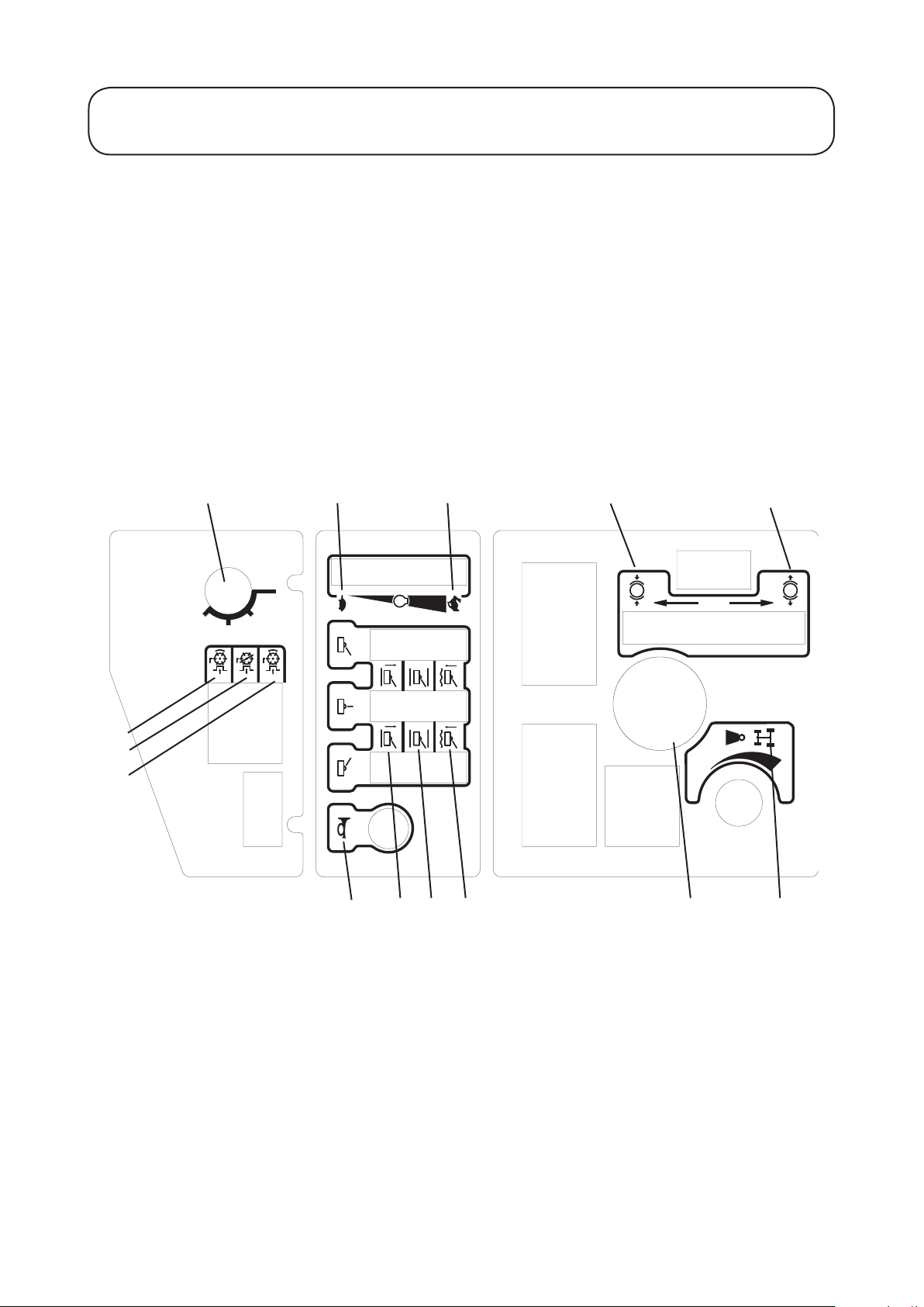
Decal - Control Panel
Part No: 924898 (A)
Location: Control Panel
A) Ignition Switch H) Cutters - Off
B) Engine Speed - Slow I) Cutters - Forward
C) Engine Speed - Fast J) Horn
D) Parking Brake - Engage K) Cutters - Lift
E) Parking Brake - Disengage L) Cutters - Hold
F) Weight Transfer - Control M) Cutters - Drop/Float
G) Cutters - Reverse N) Hour Meter
A
B C D E
G
H
I
J
NMLK
F
Page 14
1.14 1.14
SAFETY PRECAUTIONS
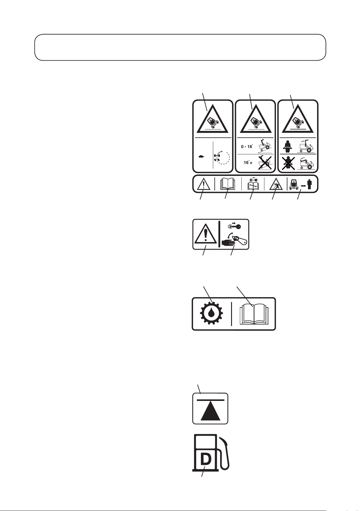
Decals continued
Decal - Inclines Part No: 111-0936 (A)
Location: Centre Platform
A) Warning - Travel slowly when turning and on
slopes
B) Warning - Maximum Slope
C) Warning - Seat belt must be worn only with a
R.O.P.S in the vertical position.
D) Caution
E) Read Operators Manual
F) Stop engine/Remove ignition key before servicing
or maintenance
G) Beware of ying objects
H) Keep bystanders clear
Decal - Danger Latch Part No: 70-13-077 (0)
Location: LH / RH / Centre Arms
A) Caution
B) Stop engine/Remove ignition key before releasing
or operating safety latches.
A
D E F
A
B
B C
G H
Decal - Transmission Oil
Part No: 111-3901 (A)
Location: Oil ller bracket mounted behind fuel tank.
A) Transmission Oil
B) Read and understand the Operators Manual.
Important: Fill the machine with the recommended oil to the correct level. Failure to do so
will cause serious damage and invalidate the
warranty.
Decal - Jacking/Support Point
Part No: 70-13-072 (0)
Location: Front Axle - 2 points
Rear Towing eye
A) Jacking and Support Point
Decal - Diesel
Part No: 70-13-078 (0)
Location: Fuel Tank
A) Diesel fuel only
A B
A
A
Page 15

0.7 BAR
10 PSI
1.4 BAR
20 PSI
1.15 1.15
SAFETY PRECAUTIONS
Decals continued
Decal - Engine Fan/Radiator
Part No: 111-3902 (A)
Location: Engine Fan Cowl
A) Danger of severing ngers
B) Caution
C) Warning - Hot Surfaces
D) Read and understand the Operators Manual
Important: Only remove radiator cap when the engine
is cool.
Decal - Tyre Pressure
Part No: 950832 (2)
Location: LH/RH Chassis - 4 places
A B C D
A
A) Mowing
B) Road Travel
Decal - Diff Lock / Control Pedal
Part No: 924812 (0)
Location: Centre Platform
A) Differential lock
B) Depress to engage diff-lock
C) Release to dis-engage diff-lock
D) Forward speed & directional control
E) Reverse speed & directional control
Decal - Noise
Part No: 922854 (0)
Location: Base of seat on GRP
B
A
B
E
DC
Page 16

105
dB
Code Serial No:
02740
310000001
LT3240
4WD TRIPLE BASE UNIT
kg:1025
RPM
:2850 kW:26.1
SPELLBROOK, BISHOP'S STORTFORD,
HERTS. CM23 4BU. ENGLAND.
2010
1.16 1.16
SAFETY PRECAUTIONS
Decals continued
Decal - Warning Crush Hazard
Part No: 111-0773 (A)
Location: Side of the ROPS frame
A) Safety Alert - Be aware to the possibility of injury
B) Crushing ngers. Force applied from side
Decal - Warning Hot Surface
Part No: 950889 (1)
Location: Right hand side of the machine
A) Safety Alert - Be aware to the possibility of injury
B) Warning - Hot surface
Decal - Serial Number
Location: Rear Bulkhead
A
A
B
B
Decal - Prevent Platform Damage
Part No: 111-3909 (A)
Location: Platform, Seat well
A) Engage parking brake
B) Lower cutterheads
C) Caution
D) Raise/lower platform
E) Read and understand the Operators Manual
Decal - Warning Platform Latch
Part No: 924868
Location: Next to Platform Latch
WARNING - PREVENT ACCIDENTS: Ensure
platform is correctly seated and the latch is fully
locked before operating the machine.
A
B
C
D
E
Page 17
1.17 1.17
SAFETY PRECAUTIONS
Decals continued
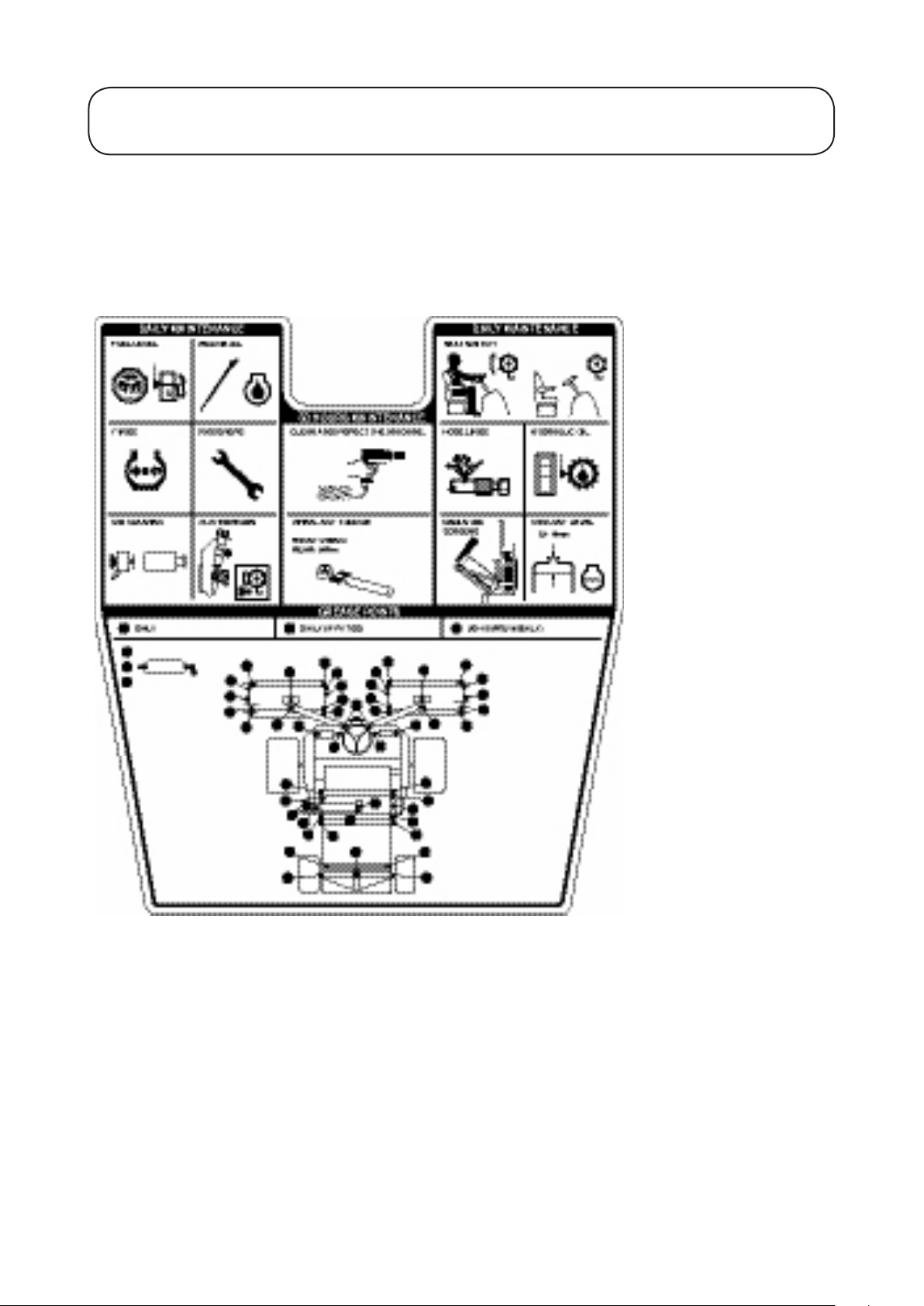
Decal - Maintenance LT3240
Part No: 924882 (2)
Location: Underside of engine
cover next to latch
Page 18

105
dB
Code Serial No:
02740
310000001
LT3240
4WD TRIPLE BASE UNIT
kg:1025
RPM
:2850 kW:26.1
SPELLBROOK, BISHOP'S STORTFORD,
HERTS. CM23 4BU. ENGLAND.
2010
1.18 1.18
EC CONFORMITY INFORMATION
Noise Levels
Operator Daily Personal Noise Exposure:
TORO have no control over site conditions, duration of
use, state of maintenance or adjustment of the mower.
All of these factors will affect the operator’s daily
personal noise exposure level - L
Under typical working conditions operators could be
exposed to a daily personal noise exposure level in
excess of 85 dB (A) L
Sound pressure level:
The sound pressure level at the operator’s position is 84
dB (A) measured in accordance with European Standard
EN836.
Sound power level:
The guaranteed sound power level is 105 dB (A)
measured in accordance with EC Directive 2000/14/EC.
EP,d
EP,d
If hearing protection is required, ear protectors with good
attenuation in the 63 - 8000 Hz frequency range should
be used.
Employers of personnel using this machine should refer
to the 2003/10/EC Directive for minimum health and
safety requirements regarding exposure and risks to
physical agents (noise).
Vibration Levels
Operator Daily Personal Vibration Exposure:
TORO have no control over site conditions, duration of
use, state of maintenance or adjustment of the mower.
All of these factors will affect the operator’s daily
personal vibration exposure level.
Under certain working conditions the operator may be
exposed to vibration levels above those stated.
Wear Hearing
Protection
Page 19
Manufactured for: T oro Company
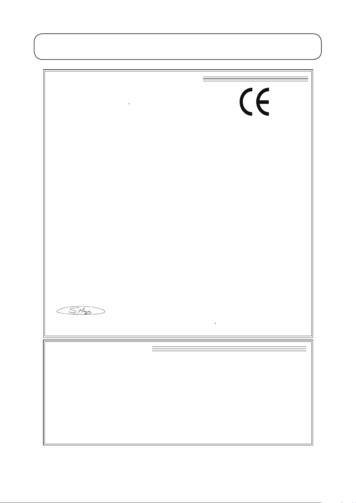
EC DECLARATION OF CONFORMITY
By: Hayter Limted
declare that thelawnmower
Model name:
Type:
Model No:
Cutting width:
Speed of rotation of the
cutting device:
Engine manufacturer:
Speed of rotation of engine:
Complies with the provisions of Directive: 2006/42/EC Essential Health & Safety Requirements relating to the Design &
Construction of Machinery and Safety Components and the regulations transposed into national law.
Also Directive 2004/108/EEC Electromagnetic Compatibility and the regulations transposed into national law.
Also Directive 79/622/EEC Roll-over protection structures of wheeled agricultural or forestry tractors (static testing), as
amended and the regulations transposed into national law.
Also Directive 2000/14/EC Noise emission in the environment by equipment for use outdoors, as amended and the regulations
transposed into national law.
Procedure applied for the conformity assessment: ANNEX VI, proced ure 1.
Notified Body: Sound Research Laboratories Ltd. Holbrook House, Little Waldingfield, Sudbury, Suffolk. CO10 0TH.
ENGLAND
Notified body identification No: 1088
Measured sound power level:
Guaranteed sound power level:
Authorised Signatory:
S.A Maryniak
(Technical Director)
Declaration done and technical documentation kept at:
HAYTER LIMITED
Spellbrook, Bishop s Stortford,
Herts. CM23 4BU ENGLAND
Date: 12.04.2010
VIBRATION INFORMATION
Address: Spellbrook, Bishop s Stortford, Herts. CM23 4BU. ENGLAND
Hand / Arm Vibration Level at the Operator Position measured in accordance with European Standard EN 836:
Measured Vibration Level ahv =
Uncertainty of measurement K =
Whole Body Vibration Level at the Operator Seat measured in accordance with European Standard EN 836:
Measured Vibration Level aw =
Uncertainty of measurement K =
SOUND PRESSURE INFORMATION
Sound Pressure Level at the Operator Position measured in accordance with European Standard EN 836:
Measured Sound Pressure Level LPA =
Uncertainty of measurement K =
ms
-2
dB(A)
ms
-2
ms
-2
ms
-2
dB(A)
LT3240
Ride-on cylinder
02740
212 cm
1050 rpm
Kubota
2850 rpm
0.5
0.5
0.2
0.1
02740
101 dB(A)
105 dB(A)
84
2
02740
02740
1.19 1.19
EC CONFORMITY INFORMATION
Page 20

1.20 1.20
INTRODUCTION
Introduction
The Toro LT3240 is a diesel engine powered self propelled machine with hydraulic systems for ground drive,
cutterhead drives and steering. It operates in two wheel drive with automatic four wheel drive on demand. A
differential lock function may be selected. The transmission system is converted automatically to engage drive to
all 4 wheels when the machine speed decreases as a result of front wheel traction slip. 2WD is automatically
re-engaged when traction slip is reduced.
The LT3240 mower is a precision built machine designed solely for cutting grass and similar low lying ground
vegetation within the limitations stated in this manual. Use in any other way is considered as contrary to the
intended use. Compliance with and strict adherence to the conditions of operation, service and repair as specied
in this Operators Manual also constitute essential elements of the intended use. The way in which this machine is
operated and maintained will have a profound effect on its performance and reliability.
This manual contains advice on the LT3240 mower which should be operated, serviced and repaired only by
persons who are familiar with its particular characteristics and who are acquainted with the relevant safety procedures.
The safety precautions listed herein and all other generally recognised regulations on safety and all road trafc
regulations must be observed at all times.
Any unauthorised modications carried out to this machine may relieve TORO of liability for any resulting
damage or injury.
In the pursuit of continuous product development TORO reserve the right to alter specications without notice.
Cutterhead Variants: The LT3240 can be tted with a range of cutterhead congurations and optional extras:
Floating Heads with
Cutterhead Cylinder diameter Number of blades Fixed Heads
MK3 Cutterhead 200mm (8˝)
254mm (10˝)
Optional Extras:
Beacon Kit - Amber ashing warning light.
Lighting Kit - Complies with EC trafc regulations.
R.O.P.S. Cab - Full weather protection and roll - over protection (Available in standard, deluxe and super deluxe).
Cab Tilt Kit - Enables the cab to be tilted.
Deluxe Seat Kit - Vinyl covering, includes air suspension unit, head rest, lumbar support and extended arm rests.
Note: with a ROPS cab tted the stability angle will decrease, due to the higher centre of gravity of the
machine.
4, 6, 8, 10
4, 6, 8
Yes
Yes
smooth or grooved front
rollers
Yes
No
When tting optional extra kits to the mower be sure to x the serial number decal supplied with the kit to the
chassis LH side. This will help the spare parts department to supply the correct spare parts throughout the service
life of the mower.
Left and right: Throughout this manual the terms ‘left’ and ‘right’ refer to the machine when looking in the
direction of forward travel.
Page 21

1.21 1.21
SPECIFICATIONS
Specications
ALL FIGURES ARE NOMINALLY QUOTED AT THE RATED ENGINE SPEED OF 2800 RPM
UNLESS OTHERWISE STATED.
Engine
LT3240
Type: Kubota V1505-E2B
4 cylinders in line
Power Rating: 24 kw (35.1 hp) @ 2800 rpm
DIN 70020
Capacity: 1498 cc (91.4 cu in)
Air Cleaner: Clean air drawn through a screened
air intake in-front of radiator via a
cyclonic air cleaner with built in
pre-cleaner.
Cooling System: Water cooled
Battery: 12V 480 Amps S. A. E.
Alternator: 40 Amps
Starter: 1.4 kw (1.6 hp) Electric
Cold Starting: Glow plug
Idle Speed: 1250 (± 50) rpm
Fuel Type: Diesel
IMPORTANT - PREVENT DAMAGE: For further information regarding the engine, refer to the Engine
Manual.
Transmission System
Drive Type: Hydraulic
Pump: Variable displacement hydraulic piston pump with integral charge pump
and pedal control.
Wheel Motors: Front Axle - radial piston, xed displacement, with integral disc
brake (pressure released)
Rear Axle - gear motor, xed displacement
Differential Lock: Electro - hydraulic control valve with pedal control
Drive: Automatic 4WD on demand (forward and reverse, selectable), with
differential lock.
Relief Valve Setting: Main service relief 300 bar (4350 psi) differential
Charge pressure relief 18.5 bar (268 psi) differential
Page 22

1.22 1.22
SPECIFICATIONS
Cutterhead Drive System
Drive Type: Hydraulic
Pump: Hydraulic gear type
Delivery Rate: 31 Litres per minute (6.8 UK gallons per minute)
Cutterhead Motors: Hydraulic gear type, reversible, pressure balanced with integral
differential pressure sensing relief check valve. Direct drive
Control: Electro-hydraulic
Automatic diverter valve safety cut-off
Relief Valve Setting: 250 bar (3625 psi) differential
Cutterhead Lift System and Steering
Drive Type: Hydraulic
Pump: Hydraulic gear pump with integral relief valve
Delivery Rate: 11 litres per minute (2.9 UK gallons per minute)
Steering: Power beyond hydrostatic steering valve with priority ow to steering and
auxiliary ow to cutterhead lift system. Manual emergency steering.
Cutterhead Lift Control: Mechanical hydraulic
Relief Valve: 110 bar (1595 psi)
Weight Transfer: Variable hydraulic applied weight transfer acting on all cutterheads
Hydraulic System
Hydraulic Oil Type: Refer to RECOMMENDED LUBRICANTS AND HYDRAULIC
FLUIDS
Capacity: 40 Litres (8.8 UK gallons)
Cooling: Forced air nned tube oil cooler
Suction Line Filtration: 125 micron no bypass mesh lter
Return Line Filtration: 10 micron with 2 bar (29 psi) bypass check valve
Transmission Filtration: 10 micron no bypass pressure lter
Maximum Oil
Contamination Level: ISO Code 18/13 or better (ISO 4406)
1300 to 2500 particles / ml < 15 μ
40 to 80 particles / ml > 15 μ
Maximum Oil Temperature: 95 C (203 F)
Page 23

1.23 1.23
SPECIFICATIONS
Vehicle Specications
0 - 22 km/hr (0 - 14 mph) Forward
Travel Speed:
0 - 11 km/hr (0 - 7 mph) Reverse
Tyres Tyre Type Recommended Tyre Pressures
Turf Conditions Road Conditions Max Pressure
Front Axle
Rear Axle
Wheel Nut Torque Settings: Front Axle 200Nm (148 lbf.ft)
Rear Axle 54Nm (40 lbf.ft)
Service Brakes: Closed loop hydrostatic service braking operating on front wheels only
Parking Brake: Lever operated oil immersed disc brakes on front wheels only. Pressurised
hydraulic oil release with mechanical override for emergency towing purposes
Ground Clearance: 180mm (7.1˝) at 13mm (.5˝) cut height and with cutterheads raised
Steering: Hydrostatic rear wheel steering, emergency manual steering
Features: Tilting operator platform
Lockable engine cover
Adjustable suspension seat with folding arms
Adjustable steering column
Cutterhead parking latches with safety locks
Back lapping facility
Differential lock (selectable)
Engine coolant and hydraulic oil overheat audible warning (horn)
Variable cutterhead weight transfer/traction assistance
2WD. 4WD on demand (forward & reverse)
Hydraulic oil lter blocked telltales on control panel
Safety Features: Neutral start interlock on transmission pump, parking brake and
cutterhead drive switch.
Operator presence control (seat switch).
2 Post folding ROPS designed and tested to European Directive 79/622/EEC.
26 x 12 - 12 4 ply 0.7 bar
(10 psi)
18 x 9.5 - 8 6 ply 0.7 bar
(10 psi)
1.4 bar
(20 psi)
1.4 bar
(20 psi)
1.7 bar
(25 psi)
1.7 bar
(25 psi)
Operator Controls
Steering: Automotive padded steering wheel
Cylinder Drive: Electric switch (forward - off - reverse)
Engine Speed: Hand lever
Parking Brake: Hand lever
Forward and Reverse: Forward and reverse foot pedal
Ignition: Key start, shut - off and engine preheat
Differential Lock: Foot pedal
Cutterhead Position: Hand lever
Horn: Button switch
Weight Transfer: Hand wheel
Page 24

1.24 1.24
SPECIFICATIONS
Instrumentation
Warning Lights: Engine oil pressure
Battery charge
Engine coolant temperature
Hydraulic transmission oil temperature
Gauges: Digital hour meter
Fuel level
Hydraulic oil level sight glass
Indicator Lights: Engine pre-heat
Hydraulic return lter blocked
Hydraulic transmission lter blocked
Cutterhead drive switch off
Parking brake engaged
Transmission neutral
Weight and Dimensions
Wheel Base: 1440 mm (56.7˝)
Working Width: 2300 mm (90.6˝)
Cutting Width: 2120 mm (83.5˝)
Transport Width: 1575 mm (58˝) at 13mm (.5˝) height of cut
Overall Length: 2710 mm (107˝)
Overall Height: 1770 mm (69.7˝) with R.O.P.S folded
2424 mm (95.4˝) with R.O.P.S in its vertical operating position
Working Weight: Including 2 post R.O.P.S, 8˝ 6 blade cutterheads and full tank of fuel. It
excludes the operator and any other options.
1317 kg (2903 lb)
Recommended Lubricants and Hydraulic Fluids
Grease Points: A good quality medium grease
Engine: Refer to Engine Operators Manual
Hydraulic System:
Ambient Temperature Range
0 - 30 C (32 - 86 F) 15 - 40 C (59 - 104 F)
ISO viscosity grade
46 hydraulic oil
Should you be in any doubt please contact your TORO dealer. Using incorrect grades will cause premature wear
of hydraulic components and invalidate warranty.
ISO viscosity grade
68 hydraulic oil
Cutterhead
MK3 200 mm Cutterhead MK3 254 mm Cutterhead
Cutting Width: 762 mm (30˝) 762 mm (30˝)
Cylinder Diameter: 200 mm (8˝) 254 mm (10˝)
Cylinder Speed: 1050 rpm approx 1050 rpm approx
Height of Cut: 12 mm (.5˝) to 80 mm (3˝) 12 mm (.5˝) to 80 mm (3˝)
Number of Blades: 4, 6, 8, 10 4, 6, 8
Smooth Rear Roller: Standard Standard
Smooth Front Roller: Optional Grooved Front Roller: Optional -
Conguration: Fixed/Floating Fixed
Page 25

1.25 1.25
OPERATING THE MOWER
Safety Notice
WARNING: PREVENT ACCIDENTS - Before operating the mower it is essential that;
- The operator reads and understands this manual.
- The operator platform latching mechanism is fully engaged and in good working order, refer to
OPERATOR PLATFORM LATCHING MECHANISM.
- The daily maintenance checks have been properly carried out and the mower is in good working
order.
- The operator should wear safety clothing and eye protection. Failure to do so could result in risk to
health and safety.
- The area where the equipment is to be used is inspected and all objects which may be thrown by the
machine are removed.
Operate safely on slopes;
It is essential to follow safe working practices when working on slopes. In order to avoid potentially
hazardous situations, it is essential that the operator understands and observes the relevant safety
precautions listed in this manual, refer to SAFETY PRECAUTIONS.
This machine is tted with a R.O.P.S as standard to increase operator safety in the event of the
machine rolling over.
The R.O.P.S frame may be folded down to allow access into area of restricted height.
While the R.O.P.S is folded down it does not provide any protection in the event of a roll over and
should not be considered as a Roll Over Protective structure.
Operator Presence Control
Cutting Cylinder Drive Lockout: Drive to the cutting cylinders is only possible when the operator is seated.
If the operator raises off the seat for a period of more than one second, a switch is activated and drive to the
cutting cylinders is automatically disengaged. To re-engage drive to the cutting cylinders, the operator must
return to the seat, then operate the cutterhead drive switch to the ‘OFF’ position before moving it back to the
‘ON’ position. If the operator rises off the seat for a brief moment during normal work, drive to the cutting
cylinders is not affected.
The engine can only be started with the cutterhead drive switch in the ‘OFF’ position.
Engine Start Lockout: The engine can only be started when the forward/reverse travel pedal is in the
‘NEUTRAL’ position, the cutterhead drive switch is in the ‘OFF’ position and the parking brake is engaged.
When these circumstances are satised, switches are activated permitting the engine to be started.
Engine Run Interlock: Once the engine is started the operator must be seated before the parking brake is
released for the engine to continue to run.
Note: The engine will cut out if the operator leaves the seat without engaging the parking brake.
WARNING: PREVENT ACCIDENTS - Do not operate the turf mower if the operator presence
controls are defective in any way. ALWAYS replace faulty parts and check that they function
correctly before operating the mower.
Page 26

1
2
5
6
10
9
4
7
8
11
14
13
12
15
16
18
19
20
21
17
22
3
23
24
31
27
25
29
26
28
30
1.26 1.26
OPERATING THE MOWER
Identication of Control Panel Components
1. Parking brake lever
2. Lighting switch
(supplied with lighting kit)
3. Warning beacon switch
(supplied with beacon kit)
4. Hazard warning switch
(supplied with lighting kit)
5. Cutterhead position controls
6. Throttle control lever
7. Ignition key
8. Cutterhead drive switch
9. Dip beam / main beam light switch
(supplied with lighting kit)
10. Direction indicator switch
(supplied with lighting kit)
11. Horn button
12. Transmission oil lter indicator
13. Oil pressure indicator
14. Transmission temperature indicator
15. Return oil lter indicator
16. Battery warning indicator
17. Engine temperature warning indicator
18. Glow plug indicator
19. Cutterhead drive off indicator
20. Parking brake indicator
21. Transmission neutral indicator
22. Weight transfer control
23. Wash / wipe switch
(supplied with cab kit)
24. Hour meter
25. LH cutterhead safety latch
26. RH cutterhead safety latch
27. Centre cutterhead transport latch
28. Reverse travel pedal
29. Forward travel pedal
30. Differential lock pedal
31. Centre cutterhead safety latch
Page 27

P
1.27 1.27
OPERATING THE MOWER
Braking System
Parking brake engaged
Parking brake: Move the parking brake lever to its rear position to engage the
parking brake. Do not operate the mower with the parking brake engaged.
WARNING: PREVENT ACCIDENTS The parking brake operates on the front wheels only. Do not park the mower on a slope.
Service brakes: Service braking is achieved by the hydraulic transmission system. When the forward or
reverse travel pedals are released or the engine speed reduced, service braking becomes effective and travel
speed is automatically reduced. To increase the braking effect, push the transmission pedal into the neutral
position.
WARNING: PREVENT ACCIDENTS The service braking system will not hold the mower at a standstill. ALWAYS ensure the parking brake
is engaged to park the mower at a standstill.
Emergency braking: In the event of service brake failure, turn the ignition off to bring the mower to a
standstill.
WARNING: PREVENT ACCIDENTS Take care when using the emergency braking. Remain seated and hold on to the steering wheel to prevent ejection from the mower caused by the front wheel brakes being applied suddenly when travelling.
Throttle Control
Operate the throttle control in a forward direction to
increase the engine speed.
Operate the throttle control in a rearward direction
to reduce engine speed.
Note that the engine speed dictates the speed of the
other functions, i.e. travel, cutting cylinder, position
controls.
Travel
Forward travel: Depress the forward travel pedal
to increase forward travel speed.
Release the pedal to reduce speed.
Reverse travel: Depress the reverse travel pedal to
increase reverse travel speed.
Release the pedal to reduce speed.
Stop (Neutral): Release the forward or reverse
travel pedal.
Engine speed
Fast Slow
Page 28

1.28 1.28
OPERATING THE MOWER
Transport Latches
WARNING: PREVENT ACCIDENTS ALWAYS raise the cutterheads to the transport
position and secure with the transport latches
and safety locks when travelling between work
areas.
1
2
1
2
Front cutterhead transport latches:
Centre cutterhead transport latch:
WARNING: PREVENT ACCIDENTS Stored energy devices are charged when the
outer wing units are in the transport position.
Always operate the relevant lift controls to
provide hydraulic support for the cutterhead
suspensions before attempting to release the
transport latches.
Differential Lock
WARNING: PREVENT ACCIDENTS Do not engage the differential lock at high
speed. The turning circle will increase with the
differential lock engaged.
2
1. Transport latch
2. Safety lock
1
The differential lock is effective only when ‘work’
mode is selected.
The differential lock operates in both ‘forwards’
and ‘reverse’ and can be engaged whilst the mower
is travelling slowly. Engage the differential lock to
prevent excessive power requirements by operating
with differential lock at SLOW speed.
Engaging differential lock:
Depress the differential lock pedal.
Disengaging differential lock:
Release the differential lock.
Page 29

2
1
A
B
1.29 1.29
OPERATING THE MOWER
Speed Control Pedals
The speed control pedal can be adjusted to provide
two speed ranges.
Securing the speed control cable through hole ‘A’
will provide 0-22 km/hr (0-14 mph) forward and
0-11 km/hr (0-7 mph) reverse. Securing the cable
through hole ‘B’ will provide 0-19 km/hr (0-12
mph) forward and 0-8 km/hr (0-5 mph) reverse.
WARNING: PREVENT ACCIDENTS - Ensure that the control cable is securely fastened
to the travel control pedal mechanism. Ensure
that both the cable and pedal articulate freely
through their full range of travel and that the
mechanism freely returns to neutral when
released.
WARNING: PREVENT ACCIDENTS - Ensure that the control cable is correctly routed
underneath the operator platform such that it is
clear of any obstructions and impediments to its
operation.
Operator Platform Latching Mechanism
WARNING: PREVENT ACCIDENTS -
Never operate the mower without rst checking
that the operator platform latching mechanism
is fully engaged and in good working order.
Check behind the seat and ensure that the top
of the platform is ush with the top of the fuel
tank. Also check beneath the tool tray and
ensure that the release lever is padlocked in the
correct position.
IMPORTANT: PREVENT DAMAGE Engage the parking brake and lower the
cutterheads to the ground. Remove ignition key
and close ignition key and close ignition cover
before raising and lowering the platform.
Releasing the platform: Release and remove the
tool tray from the left hand side of the platform.
Release the padlock securing the locking latch
handle with key provided. Move the locking latch
handle towards the front of the mower (position A)
until the latch hooks clear the locking bar and raise
the platform. The gas spring will provide
assistance.
1. Tool tray
2. Locking latch handle
A. Release
B. Securing
3. Padlock
Page 30

3
A
A
1.30 1.30
OPERATING THE MOWER
Operator Platform Latching Mechanism
Cont’d
Securing the platform: Lower the platform
carefully. The gas spring will provide assistance.
Move the locking latch handle towards the front
of the mower (position A) as the platform nears
the fully lowered position. This will ensure that the
latch hooks clear the locking bar. Fully lower the
platform and move the locking handle towards the
rear of the mower (position B) until the latch hooks
fully engage the locking bar. Replace the padlock
in order to secure the locking latch handle in place.
Adjustable Steering Column
WARNING: PREVENT ACCIDENTS Before operating the mower, ensure that the
steering column adjuster mechanism is in good
working order and that the steering wheel is
locked securely in position.
WARNING: PREVENT ACCIDENTS Adjustment of the steering wheel and steering
column should only be carried out when the
mower is at a standstill with the parking brake
engaged.
Adjusting the angle of inclination of the steering
wheel: Move lever ‘A’ downwards to adjust the
angle of steering wheel. Release the lever to lock
the steering wheel in position.
Adjusting the length of the steering column:
Move the lever ‘A’ upwards to adjust the length of
the steering column. Release the lever to lock the
steering column in position.
Page 31

1
2
3
4
3
4
1.31 1.31
OPERATING THE MOWER
Folding the R.O.P.S
The R.O.P.S frame may be folded down to allow access into areas of restricted height.
WARNING: PREVENT ACCIDENTS - While the R.O.P.S frame is folded down it does not
provide any protection in the event of a roll-over and should not be considered as a Roll Over
Protective Structure.
1. Lower the cutterheads, apply the parking brake and switch off the engine.
2. Support the weight of the upper frame (item 1) while removing the hand nuts, washers and retaining
bolts (items 2, 3 & 4) from the pivot brackets. Refer to Fig 2.
3. Carefully lower the frame downwards until it rests on the stops.
4. Insert the retaining bolts in the lower hole and fully tighten the hand nuts to support the upperframe in its
lowered position.
5. To raise the frame, follow these instructions in reverse order.
WARNING: PREVENT ACCIDENTS - When in the raised position, both retaining bolt
assemblies (items 2, 3 & 4) must be installed and fully tightened to ensure full R.O.P.S protection.
WARNING: PREVENT ACCIDENTS - Be careful lowering and raising the R.O.P.S frame to
prevent entrapment of ngers between xed part and pivot part of the structure.
Keep all nuts, bolts and screws correctly torqued ensure that the equipment is in safe working condition.
Replace worn or damaged parts for safety.
Ensure that the seat belt and mountings are in safe working order.
Fig 2
Page 32

B
C
D
CW
CCW
E
1.32 1.32
OPERATING THE MOWER
Operator Seat
WARNING: PREVENT ACCIDENTS - Before operating the mower ensure that the operator seat
mechanisms are in good working order and that the seat is locked securely in position.
WARNING: PREVENT ACCIDENTS - Adjustment of the seat mechanisms should only be carried out
when the mower is at a standstill with the parking brake engaged.
Fore/Aft Adjustment: Move lever ‘B’ upwards to
adjust the Fore/Aft position of the seat. Release the
lever to lock the seat in position.
Operator weight adjustment: Rotate handle ‘C’
clockwise as shown to increase suspension stiffness
and counter-clockwise to decrease. Dial ‘D’ indicates
when the optimum suspension has been set according
to operator weight (kg).
Height adjustment: Manually lift the seat for
incremental height adjustment. To lower lift the seat
to beyond its highest setting, then allow it to drop to
the lowest setting.
Backrest adjustment: Pull handle ‘E’ outwards to
adjust the seat backrest angle. Release the handle to
lock the seat backrest in position.
Page 33

1.33 1.33
OPERATING THE MOWER
Warning Systems
Engine coolant overheating warning:
The engine coolant warning light illuminates, the
horn is actuated and the cutters stop.
Hydraulic oil overheating warning:
The hydraulic oil warning light illuminates and
the horn is actuated when the hydraulic oil in the
reservoir exceeds 95˚ C (203˚ F) approx.
Low battery charge warning:
The battery charge warning light illuminates.
Low engine oil pressure warning light:
The engine oil pressure warning light illuminates.
Audible Warning Horn
Depress the horn button to provide an audible
warning.
IMPORTANT: PREVENT DAMAGE - The
horn is automatically actuated when an engine
coolant or hydraulic oil overheat condition
occurs. STOP the engine immediately and effect
remedial action before restarting.
Page 34

I
II
III
O
FUEL
E
F
D
3 4 5 5 9
1.34 1.34
OPERATING THE MOWER
Ignition Key
0 = Engine off.
I = Engine run / Auxiliary on.
II = Engine pre-heat.
III = Engine start.
WARNING : PREVENT ACCIDENTS - Always remove the ignition key when the mower is not in use.
IMPORTANT: PREVENT DAMAGE - Always t the protective cap when the ignition key is removed
to prevent ingress of dirt and moisture from damaging the mechanism.
Engine Pre-Heat Indicator Light
Turn the ignition key to position II. The engine
pre-heat indicator light will illuminate. When the
correct pre-heat temperature is achieved, the indicator
light will switch off. When this condition is achieved,
turn the ignition key to position III to start the engine.
IMPORTANT: PREVENT DAMAGE - Attempting to start a cold engine before the pre-heat is used
can cause unnecessary wear to the battery.
Fuel Level Gauge
Displays fuel tank level.
E = Empty
F = Full
Hour Meter
Displays engine running hours.
Page 35

N
P
1.35 1.35
OPERATING THE MOWER
Transmission Neutral Indicator Light
Illuminates when the travel control pedal is in the
neutral position and the ignition key is turned to
position ‘I’.
Note: The parking brake must be engaged for the
transmission neutral indicator light to illuminate.
Cutterhead Drive Switch Indicator Light
Illuminates when the cutterhead drive switch is in
the ‘off’ position and the ignition key is turned to
position ‘I’.
Parking Brake Indicator Light
Illuminates when the parking brake is engaged and
the ignition key is turned to position ‘I’.
Hydraulic Return Filter Indicator Light
Illuminates when the return lter element is blocked.
Note: The engine must be running for the hydrau-
lic return lter indicator light to illuminate. The
indicator light may illuminate briey when the
hydraulic oil is cold.
Hydraulic Transmission Filter Indicator
Light
Illuminates when the transmission lter element is
blocked.
Note: The engine must be running for the hydrau-
lic return lter indicator light to illuminate. The
indicator light may illuminate briey when the
hydraulic oil is cold.
Page 36

1
2
3
1.36 1.36
OPERATING THE MOWER
Cutterhead Position Control
The cutterheads may be raised or lowered
independently using the bank of 3 lift control
levers.
To lower the cutterheads, operate the lift control
levers in a downward direction until locked into
position. If the cutterhead drive switch is in the
‘on’ position, the cylinder drive will engage when
the cutterheads are approximately 300mm (11.8)
above ground level.
IMPORTANT: PREVENT DAMAGE - The lift
control levers must be locked in position 1 while
moving. NEVER mow with the lift control levers
in position 2 (neutral).
To raise the cutterheads, operate the lift control
levers in an upward direction and hold in
position 3. If the cutterhead drive switch is in the
‘on’ position, the cylinder drive will disengage
when the cutterheads are approximately 300mm
(11.8) above ground level. Release the lift control
levers when the cutterheads are at the required
height. The control levers will automatically return
to position 2 (neutral).
1
2
3
4 5 6
1. Down/oat
2. Neutral
3. Raise
4. LH cutterhead
5. Centre cutterhead
6. RH cutterhead
Cutterhead Drive Engagement
The cutterhead drive can be engaged only when the
operator is seated correctly, refer to OPERATOR
PRESENCE CONTROLS.
Briey operate the lift control levers to raise the
cutterheads, thereby removing the cutterhead
suspension deadweights and wing units stored energy reaction from the transport latch mechanisms.
Release the cutterhead latches. Operate the cutterhead position controls to the down / oat position
and lower all cutterheads to the ground ready for
mowing.
Forward rotation cutterhead drive engagement:
Operate the cutterhead drive switch to the ‘Forward’ position.
Reverse rotation cutterhead drive engagement:
Operate the cutterhead drive switch to the ‘Reverse’
position.
To disengage all cutterhead drives: Operate the
cutterhead drive switch to the ‘Off’ position.
1. Forward
2. O
3. Reverse
WARNING: PREVENT ACCIDENTS - Refer
to OPERATOR PRESENCE CONTROLS for
additional information.
Page 37

1
2
3
I
II
III
O
1
1.37 1.37
OPERATING THE MOWER
Weight Transfer / Traction Assistance
A variable hydraulic weight transfer system is provided for improving tyre grip with the grass surface
- ‘Traction Assistance’.
Hydraulic pressure in the cutterhead lift system
provides a lifting force which reduces cutterhead
weight on the ground and transfers the weight as a
downward force onto the mower’s tyres. This action is known as ‘Weight Transfer’.
To engage weight transfer: The amount of weight
transfer can be varied to suit operating conditions
by rotating the weight transfer hand wheel as follows;
Release the lock wheel underneath the hand wheel
1
/2 turn anti-clockwise and hold.
1. Weight transfer hand wheel
2. Lock wheel
3. Control panel
Rotate the hand wheel:
- Anti-clockwise to reduce weight transfer.
- Clockwise to increase weight transfer.
Tighten the lock wheel.
Starting The Engine
WARNING: PREVENT ACCIDENTS - Before
starting the engine check that;
- You have read and understood the Safety
Precautions section in this manual.
- The area is clear of bystanders.
- The cutterhead drive is disengaged.
- The parking brake is engaged.
- The travel control pedals are in neutral.
This machine is tted with an Engine Start
Lockout, refer to OPERATOR PRESENCE
CONTROLS.
Starting a cold engine: Set the throttle control
lever to approximately 70% full throttle.
Turn the ignition key to the ‘ignition on’ position
‘I’ and check that the engine oil pressure and battery charge warning lights illuminate.
Turn the ignition key to the ‘preheat’ position ‘II’
and hold until the engine pre-heat indicator light
goes out.
1. Engine pre-heat indicator light
Page 38

I
II
III
O
1.38 1.38
OPERATING THE MOWER
Starting The Engine Cont’d
Turn the ignition key to the ‘start’ position ‘III’
and hold to crank the engine. As soon as the engine
starts release the ignition key back to position ‘I’.
WARNING: PREVENT DAMAGE - When the
engine is operating all warning lights should
be ‘off’. If a warning light illuminates, stop the
engine immediately and have the fault rectied
before restarting.
Starting a warm engine: Engine pre-heating is
unnecessary when restarting an engine which has
been stopped for a few minutes. Follow the cold
engine starting procedure without holding in
‘preheat’ position ‘II’.
Stopping The Engine
To stop the engine: Turn the ignition key to
position ‘0’.
WARNING: PREVENT ACCIDENTS - If the
engine fails to stop when the ignition key is
turned to ‘O’ operate the engine stop lever in a
forward direction. Keep hands clear of moving
objects and hot engine parts whilst the engine is
running.
Unblocking Cutting Cylinders
WARNING: PREVENT ACCIDENTS - Before
attempting to clear any blockage from the
cutting cylinders on this machine ensure all of
the following:
- Stop the machine on level ground.
- Apply the parking brake and disengage all
drives.
- Lower the cutting units to the ground or
securely lock in the designated transport
positions.
- Stop the engine and remove the ignition key to
isolate all power sources and check that they
are stopped.
- Release all stored energy devices.
- Check that all moving parts are stationary.
1
1. Engine STOP position
Page 39

1.39 1.39
OPERATING THE MOWER
Unblocking Cutting Cylinders Cont’d
NEVER ATTEMPT TO ROTATE THE
CUTTING CYLINDERS BY HAND as there
may be some residual pressure in the hydraulic
system which could cause injury through sudden
movement of the cylinder(s) when the blockage is
released.
Always wear protective gloves and use a suitable
strong wooden instrument. Ensure that this will t
between the blades and through the cylinder and
is long enough to provide sufcient leverage to
release the blockage and any residual hydraulic
system pressure by rotating or rocking the cylinder.
Make sure that the wooden instrument is properly
supported in the cylinder and avoid the use of
excessive force to prevent damage.
Only when the cylinder has a degree of free
movement should the source of the blockage be
removed. Ensure that the wooden instrument is also
removed before restarting the power source.
If the cylinder requires readjustment or repair, refer
to MAINTENANCE - CUTTERHEADS.
Centre Cutterhead Height of Cut
Correction Adjustment
With all cutterheads set at the same HOC via the
indicator rings, it may be noticeable that the centre
unit produces a higher cut nish compared to the
wing units. The centre unit is pulled and the wing
units are pushed this presents marginally different
cutting angles relative to the ground. The amount
of HOC variation, which results from this will be
inuenced by the terrain but satisfactory results can
usually be achieved by setting the centre cutterhead
HOC indicator ring lower than the wing unit
settings.
Page 40

1.40 1.40
OPERATING THE MOWER
General Operating Hints
1. The rotational speed of the cutting cylinders should always be kept as high as possible in order to
maintain the highest quality of cut. This in turn requires that the engine speed be kept as high as
possible.
2. The quality of cut will deteriorate if the forward speed is excessive. Always balance the quality of
cut with the work rate required and set the forward speed accordingly.
3. Never let the engine labour. Reduce the forward speed or increase the height of cut. Check that the
cutting cylinders are not in heavy contact with their bottom blades.
4. Regularly check the cutting cylinder to bottom blade adjustment every few hours even though
cutting performance appears to be satisfactory. Heavy contact or excessive clearances between the
cylinder and bottom blades will cause rapid wear to take place.
5. Always disengage the cutterhead drive when travelling across un-grassed areas. Grass will lubricate
the cutting edges whilst mowing. Excessive heat will build up if the cutting cylinders are run when
not mowing and this will cause rapid wear to take place. For this reason it is also wise to reduce
cutting speed when mowing lightly grassed areas or when the grass is dry.
6. Cutting performance is best when cutting against the lie of the grass. In order to take advantage of
this fact, the operator should attempt to alternate the direction of mowing between cuts.
7. Take care not to leave uncut strips of grass at the overlap points between adjacent cutterheads by
avoiding tight turns.
8. It is generally wise to remove rear roller scrapers where conditions allow, as optimum grass dis-
charge is achieved without them. Scrapers should be retted when conditions are such that mud and
grass start to build up on the rollers. When retting the scraper wires care must be taken to ensure
that they are correctly tensioned, refer to MAINTENANCE - EVERY 50 HOURS.
WARNING: PREVENT ACCIDENTS - Take care when travelling over obstacles such as roadside
kerbs. ALWAYS travel at slow speed over obstacles to prevent damage to the machines tyres, wheels
and steering system. Ensure that tyres are inated to the recommended pressures.
Page 41

1.41 1.41
OPERATING THE MOWER
Cutterhead General Information
The mower is designed to be used with MK3 200mm (8˝) xed or oating cutterheads or MK3 254mm (10˝)
xed cutterheads.
It is essential that the relationship between the bottom blades and the cutting cylinders are kept in good adjustment and that cutting edges are kept sharp to ensure good cutting performance, minimum power consumption and prolonged life for the cutting edges, refer to MAINTENANCE - CUTTERHEADS.
MK3 Fixed Cutterheads 200mm (8˝) / 254mm
(10˝): When the mower is set up with xed cutter-
heads the height of cut is gauged by the rear roller
and the cutterhead is allowed to pivot laterally to
follow ground contours. This arrangement is normally recommended for general mowing require-
ments.
(MK3 200mm (8˝) Cutterhead illustrated).
MK3 Floating Cutterhead 200mm (8˝): When
the mower is set up with oating cutterheads the
height of cut is gauged by the front and rear rollers.
The cutterhead is allowed to pivot fore and aft as
well as laterally. This arrangement is recommended
for high quality grass areas and performs well
where grass is short and the ground undulations are
severe.
Grass deectors: The rear grass deectors must
always be correctly tted. The deectors should be
set as low as possible to deect grass discharge to
the ground.
WARNING: PREVENT ACCIDENTS - Always
ensure that the grass deectors are angled below
horizontal level, otherwise risks to health and
safety may result.
Height of cut gauge: An optional height of cut
gauge is available to assist in achieving accurate
cut height settings. It is suitable for both xed and
oating cutterheads.
TORO part no. 63-01-760
Page 42

B
E
C
E
=
B
E
C
E
=
1.42 1.42
OPERATING THE MOWER
MK3 200 mm (8˝) Fixed Cutterhead
Pivot knuckle xing: Secure the bolt in the
front “xed” hole position ‘A’ as shown.
Height of cut adjustment: The height of cut is
gauged by the position of the rear roller.
Turn the adjusting nut assembly ‘B’ both ends
clockwise to decrease height of cut ‘E’ or anticlockwise to increase height of cut ‘E’.
IMPORTANT: PREVENT DAMAGE - Do not
attempt to unlock the nut assemblies, ‘B’.
Ensure that all cutterheads are set at the same
height of cut by either referring to the indicator
rings ‘C’ or by using a height of cut gauge across
the full width of each cutterhead for greater accuracy as shown.
A
MK3 254 mm (10˝) Fixed Cutterhead
Height of cut adjustment: The height of cut is
gauged by the position of the rear roller.
Turn the adjusting nut assembly ‘B’ both ends
clockwise to decrease height of cut ‘E’ or anticlockwise to increase height of cut ‘E’.
IMPORTANT: PREVENT DAMAGE - Do not
attempt to unlock the nut assemblies, ‘B’.
Ensure that all cutterheads are set at the same
height of cut by either referring to the indicator
rings ‘C’ or by using a height of cut gauge across
the full width of each cutterhead for greater accuracy as shown.
Page 43

B
A
D
E
A
C
E
=
1.43 1.43
OPERATING THE MOWER
MK3 200 mm (8˝) Floating Cutterhead
Pivot knuckle xing: Secure the bolt in the rear
‘oating’ slot position ‘A’ as shown.
Height of cut adjustment: The height of cut is
gauged by the position of the front and rear rollers.
To alter the rear roller position, turn the adjusting
nut assembly ‘B’ both ends clockwise to decrease
height of cut ‘E’ or anti-clockwise to increase
height of cut ‘E’.
IMPORTANT: PREVENT DAMAGE - Do not
attempt to unlock the nut assemblies, ‘B’.
To alter the front roller position loosen bolts ‘F’.
Release and turn adjusting nuts ‘D’ both ends
clockwise to increase the height of cut or anticlockwise to decrease the height of cut.
Ensure that all cutterheads are set at the same
height of cut by referring to the indicator rings ‘C’
or use the height of cut gauge across the full width
of each cutterhead as shown.
Tighten nuts ‘D’ and ‘F’ both ends.
Page 44

1.44 1.44
MAINTENANCE
Maintenance
WARNING: PREVENT ACCIDENTS - When carrying out maintenance procedures it is essential that:
- The engine is switched off and the ignition key removed.
- The parking brake is applied.
- There is no pressure in the hydraulic system.
- The cutterheads are fully down on the ground.
- The safety precautions in this manual have been read and understood.
WARNING: PREVENT ACCIDENTS - Stored energy devices and systems are used on the T4240
mower. It is essential that this stored energy is safely dissipated before maintenance or other service or
operations are performed on these devices and systems on the machine.
Dissipate stored energy as described below:
Hydraulics:
Transmission System: Ensure that the machine is on level ground, engage the parking brake and switch the
engine off. Depress for forward and reverse travel pedals alternatively several times.
Cutterhead Lift System: Lower the cutterheads to the ground and switch the engine off. Raise and lower the
lift levers several times leaving them in the ‘down/oat’ position.
Cutterhead Drive System: Lower the cutterheads to the ground with the cutterhead drive switch in the ‘off’
position and switch the engine off.
Operator Platform Gas Spring: Raise the platform fully.
IMPORTANT: PREVENT DAMAGE - Regular maintenance is essential for the continued safe
operation of the machine. Correct servicing will prolong the working life of the machine and safe-
guard the ‘Warranty’. Always t genuine ‘TORO service parts’ as these are accurately matched to the
required duty.
Dirt and contamination are the enemies of any hydraulic system. When carrying out maintenance procedures
on the hydraulic system always ensure that the work area and the components are thoroughly clean before,
during and after retting. Ensure that all open hydraulic lines and ports, etc. are plugged during maintenance
procedures.
The recommended service intervals are based on normal operating conditions. Severe or unusual conditions
will necessitate shorter service intervals.
ALWAYS grease pivot points immediately after pressure washing or steam cleaning, refer to EVERY 50
HOURS, GREASE PIVOT POINTS.
WARNING: PREVENT ACCIDENTS - The engine, transmission oil and hydraulic systems will be hot
after machine use. Allow the systems to cool before working on the machine, particularly before work-
ing on the engine or when changing oil or oil lters.
Page 45

1.45 1.45
MAINTENANCE
Maintenance continued
WARNING: PREVENT ACCIDENTS - Use hazardous substances carefully.
The following uids are identied as being hazardous;
Substances Assessed risk
Diesel oil Low
Lubricating oil Low
Hydraulic oil Low
Grease Low
Anti - freeze Medium
Battery acid High
When using any of the above uids it is recommended that eye protection and gloves are worn and that
care is taken to prevent spillage.
Avoid contact with skin; wash off spillage with soap and water.
In the case of battery acid drench with water and seek medical attention. Remove any contaminated
clothing and clean thoroughly before use.
Avoid contact with eyes; wash with running water and seek medical attention if symptoms persist. In
the case of battery acid, seek medical attention immediately.
Avoid ingestion; if swallowed seek medical attention.
Keep clear of high pressure uid escaping from pinholes, cracked connections etc. High pressure uid
can penetrate the skin. Seek immediate medical advice if any uid is injected into the skin. Always use
a piece of cardboard or paper when searching for leaks.
CAUTION: PREVENT ENVIRONMENTAL DAMAGE - Dispose of hazardous substances
correctly.
When disposing of hazardous waste products, take them to an authorised disposal site.
Waste products must not be allowed to contaminate surface water, drains or sewerage systems.
CAUTION: PREVENT ENVIRONMENTAL DAMAGE - Dispose
of used battery correctly. The battery has a separate collection mark.
This means that the battery must not be disposed of with general waste.
It must be taken to an authorised disposal site
Page 46

ENGINE
1
2
3
1
2
1.46 1.46
MAINTENANCE
Engine
Refer to the ENGINE OPERATOR’S MANUAL
for maintenance information.
Running In Period
Check wheel nut torque settings:
During rst 50 hours of use and in addition to
routine checks. Refer to DAILY AND BEFORE
USE. Check wheel nut torques twice a day.
Front axle wheel nut torque setting - 200 Nm (148
lbf.ft).
Rear axle wheel nut torque setting - 54 Nm (40 lbf.
ft).
Running In Period - At First 50 Hours
Change the transmission oil lter: Unscrew and
remove the bottom of the transmission oil lter
housing. Withdraw the lter element and discard.
Ret a new lter element (Part no. 924709) and
replace the housing.
Change the hydraulic oil return lter:
Unscrew and remove the return lter canister
and discard. Ret a new lter canister (Part no.
924692).
1. Transmission oil lter
2. Centre cutterhead
3. Hydraulic oil tank
1. Hydraulic oil return lter
2. Engine fuel lter
Page 47

30 - 40mm (1.2” - 1.6”)
1
2
3
1.47 1.47
MAINTENANCE
Daily And Before Use
Check engine oil level: If the oil level is below the
upper mark on the dipstick, top up with the correct
grade of engine oil to the required level, refer to
ENGINE MANUAL.
Check engine radiator coolant level:
WARNING: PREVENT ACCIDENTS Avoid scalding. DO NOT remove the radiator
ller cap unless the engine is cool. Turn the ller
cap slowly to release system pressure before
removing the ller cap completely.
Keep coolant between ‘full’ and ‘low’ when engine
is cold at all times.
IMPORTANT: If you see RED in the Filter Blockage Indicator the air lter needs replacing.
Cleaning the air cleaner: Remove the air lter
and tap it repeatedly with the palm of the hand to
remove dust particles. DO NOT damage the air
lter by hitting it against a hard object. Inspect the
air lter for signs of damage.
IMPORTANT: PREVENT DAMAGE -
Always replace a damaged air lter or damage
to the engine will result. NEVER run the engine
without the air lter correctly tted.
Clean the inside of the cleaner dust bowl with a dry
cloth and check that the dust boot is not obstructed.
1. Air lter
Replace the air lter and assemble the dust bowl,
with the dust boot facing below horizontal level.
2. Dust bowl
3. Dust boot
Page 48

D
1
2
3
3
4
1
2
1.48 1.48
MAINTENANCE
Daily And Before Use continued
Clean the primary radiator screen:
Clean the primary radiator screen. Check the oil
cooler, secondary screen and engine radiator grille
for debris and clean as necessary using a brush or
airline. The secondary screen can be removed for
cleaning. Re-assemble the secondary screen. If
water is used, these areas should be allowed to dry
out completely before use.
IMPORTANT: PREVENT DAMAGE NEVER operate the mower with a damaged
radiator screen or engine damage could result
from overheating. Clean the radiator screen
more regularly in dry conditions.
Check fuel level: Top up as necessary with diesel
fuel. Always top up before storing the mower overnight to prevent water condensation from contaminating the fuel.
1. Radiator primary screen
2. Oil cooler
3. Secondary screen
Check hydraulic oil level: If the oil level is below
the upper mark on the sight level gauge, top up
with the correct grade of hydraulic oil as necessary,
refer to SPECIFICATIONS.
WARNING: PREVENT DAMAGE - If there
is noticeable hydraulic oil loss, the leakage
source must be rectied before using the mower.
NEVER operate the mower when the hydraulic
oil level is below the bottom mark on the sight
level gauge. NEVER operate the mower with
contaminated oil.
Check hydraulic hose-lines: Inspect hydraulic
hose-lines for signs of wear or damage.
WARNING: PREVENT ACCIDENTS ALWAYS replace worn or damaged hydraulic
hose-lines immediately. DO NOT operate the
mower with defective hydraulic hose-lines.
Inspect the mower for signs of oil leakage. Tighten
ttings or replace seals as required.
1. Sight level gauge
2. Oil tank
3. Oil ller cap
4. Fuel tank
Page 49

1.49 1.49
MAINTENANCE
Daily And Before Use continued
Check fasteners: Check that all nuts, bolts and
pins are secured correctly in place and in good
condition.
Check safety devices:
WARNING - PREVENT ACCIDENTS: Ensure
that all safety guards, shields and protective
devices are securely in place and in good working order.
Check tyres: Examine the condition of the tyres
and check that ination pressures are correctly set,
refer to SPECIFICATIONS.
WARNING - PREVENT ACCIDENTS: Ensure
that damaged tyres are replaced. Ensure that
tyre tread depths comply with road trafc
regulations.
Grease all rear axle components including the centre axle beam pivot pin, both steering yokes, track
rod ball joints and steering cylinder ball joints,
refer to EVERY 50 HOURS, GREASE PIVOT
POINTS.
Check cutterheads: Examine the condition of
the cutting cylinders and bottom blades. Adjust as
necessary, refer to CUTTERHEAD CYLINDER
TO BOTTOM BLADE ADJUSTMENT.
Grease all cutterhead rollers with a good quality
medium grade grease and ensure that sufcient
grease is injected such that clean grease is seen to
escape from the roller end cap, refer to EVERY 50
HOURS.
If no grease can be seen escaping from the roller
end cap it can be assumed that the rear seal has
failed, resulting in the roller shell being lled with
grease.
Note: Care should be taken if an industrial
power greaser is used as this may result in
damage to the bearing sealing arrangement.
Check forward/reverse travel pedal action: With
the engine switched ‘off’, operate the forward
and reverse travel pedals through the full range of
articulation and ensure that the mechanism returns
freely to the neutral position.
Page 50

1.50 1.50
MAINTENANCE
Daily And Before Use continued
WARNING - PREVENT ACCIDENTS: Do not operate the machine if there are any signs of
‘Stickiness’ in the pedal mechanism which prevents a free return to the neutral condition.
Check operator presence controls:
WARNING: PREVENT ACCIDENTS - Keep bystanders away when checking operator
presence control interlock switches. DO NOT use the mower unless the operator presence controls
work correctly as described below. If difculties arise, consult your authorised dealer.
Operator presence seat switch: Sit on the operator seat and start the engine. Lower the cutterheads to the
ground and engage the cutter drive in the forward direction. Rise from the operators seat and check that the
cutting cylinders come to a stop after an initial 0.5 to 1 second delay. Repeat with the cutting cylinders
running in reverse.
Cutter drive interlock switch: Stop the mower engine. Operate the cutter drive switch to the ‘off’
position and turn the ignition key to position ‘I’. The cutterhead drive switch indicator light should
illuminate. Refer to OPERATING THE MOWER.
Operate the switch to the ‘forward’ position. The indicator light should go out and the engine should not
start when the ignition key is turned. Repeat for the ‘reverse’ position.
Parking brake interlock switch: Stop the engine. Engage the parking brake and turn the ignition key to
position ‘I’. The parking brake indicator light should illuminate. Refer to OPERATING THE MOWER.
Disengage the parking brake. The indicator light should go out and the engine should not start when the
ignition key is turned. Sit on the operator seat and start the engine. Release the parking brake. Rise from the
operator seat and check that the engine stops.
Transmission neutral interlock switch: Stop the mower engine and remove the foot from the forward/
reverse travel pedals. Turn the ignition key to position ‘I’ and the transmission neutral indicator light should
illuminate. Application of light pedal pressure in a forward and reverse direction should cause the indicator
light to go out. Take extreme care to ensure that the area around the mower is clear before checking that the
engine will not start under this condition.
Page 51

A
B
B
1.51 1.51
MAINTENANCE
Every 50 Hours
Perform routine checks: Refer to DAILY BEFORE USE.
Check cutterhead roller bearing adjustment:
Important: Prevent Damage - It is essential that
the cutterhead roller bearings are kept in good
adjustment in order to ensure maximum
working life. If roller end oat is allowed to
become excessive, premature bearing failure
will result.
Grip the roller and move from side to side and
up and down. If excessive movement is detected
proceed as follows:
Carefully tighten nuts ‘A’ at each end of the roller
with the spanner provided, just sufciently to
remove any end oat.
Note: The roller should still rotate freely after
adjustment. Overtightening of nuts ‘A’ could
lead to premature bearing failure.
Check cutterhead rear roller scraper wire
tension:
It is important that the scraper wires are correctly
tensioned so as to ensure correct operation and
maximum working life. Carefully tighten the
scraper wire retaining nuts ‘B’ so as to just remove
any slack from the scraper wires then tighten nuts
‘B’ a further four full turns to correctly tension the
wire.
IMPORTANT: PREVENT DAMAGE - Do not
over tighten the scraper wires.
Check wheel nut torque settings:
Front axle wheel nut torque setting - 200Nm (148
lbf.ft).
Rear axle wheel nut torque setting - 54 Nm (40 lbf.
ft).
Greasing the transmission control unit:
It is important to grease the transmission control
unit. This is done using the remote grease nipple
located adjacent to the hydraulics oil tank ller.
Pump grease into the unit until it can be seen
exuding from both ends of the control unit.
Page 52

DAILY
DAILY (IF FITTED)
50 HOUR (WEEKLY)
1.52 1.52
MAINTENANCE
Every 50 Hours continued
Grease pivot points :
Clean and grease all grease points with a good
quality compound of the grade specied, refer to
SPECIFICATIONS.
Replace any grease nipples which are damaged.
Grease all cutterhead grease points and ensure
that sufcient grease is injected such that clean
grease is seen to escape from the roller end caps.
This provides visible evidence that the roller
seals have been purged of grass debris etc. and
will ensure maximum working life.
GREASE POINTS
Page 53

Outer Cover Sleeve Rod EndRubber Seal Rubber Seal
1
2
1.53 1.53
MAINTENANCE
Every 250 Hours
Perform routine checks: Refer to - DAILY BEFORE USE.
- EVERY 50 HOURS.
Check battery condition:
WARNING: PREVENT ACCIDENTS - Explosive gases are produced by the battery. Work in a well
ventilated area, away from all sources of ignition.
Battery uids are corrosive. Take care to avoid contact with the skin or eyes. In the event of a
spillage, drench the affected area with water. If the eyes are affected, seek medical attention.
Remove any contaminated clothing and clean thoroughly before use.
When removing the battery, always disconnect the negative (-) cable rst.
When replacing the battery, always connect the negative (-) cable last.
Remove the tool tray to gain access to the battery. Remove any corrosion from the battery terminals using a
wire brush and apply petroleum jelly to the terminals to prevent further corrosion. Clean the battery compart-
ment.
Under normal operating conditions the battery will not require any further attention. If the machine has been
subject to continuous use under high ambient temperature conditions, the battery electrolyte may require
topping up. Remove the cell covers and top up with distilled water to a height 15mm below the top of the
battery. Replace the cell covers.
IMPORTANT: PREVENT DAMAGE - Check
the condition of the battery cables. Replace cables
showing signs of wear or damage and tighten any
loose connections as necessary.
1. Battery
Visually inspect transmission control cable and
2. Tool tray
operating mechanism:
Check the condition and security of the cable and
operating mechanism at the speed control pedals and
transmission pump ends.
- Remove build up of dirt, grit and other deposits.
- Ensure that the ball joints are securely anchored and check that mounting brackets and cable anchors are
tight and free from cracks.
- Inspect end ttings for wear, corrosion, broken springs and replace if necessary.
- Ensure that the rubber seals are correctly located and in good condition.
- Ensure that the articulating sleeves supporting the inner cable are in good condition and rmly
attached to the outer cable assembly at the crimped connections. If there are any signs of cracking or
detachment t new cable immediately.
- Check that sleeves, rods and inner cable are free from bends, kinks and other damage. If there are
any signs of such failure, t a new cable immediately.
- With the engine switched ‘Off’, operate the pedal controls through the entire range and ensure that
the mechanism moves smoothly and freely to the neutral position without ‘Sticking’ or ‘Hanging up’.
Page 54

3
4
1
2
ENGINE
ENGINE
1.54 1.54
MAINTENANCE
Every 500 Hours
Perform routine checks: Refer to - DAILY BEFORE USE
- EVERY 50 HOURS
- EVERY 250 HOURS.
Thoroughly clean the machine:
IMPORTANT: PREVENT DAMAGE - Keep water away from electrical components. Use a dry cloth
or brush to clean such areas.
Service the hydraulic system: This procedure is best carried out when the hydraulic oil is warm (not hot).
Lower the cutterheads to the ground and drain the hydraulic system by removing the hydraulic tank drain
plug. Remove the oil tank ller ange to gain access to the suction strainer. Unscrew and remove the strainer
and clean with parafn or petrol before replacing. Renew the strainer if there are any signs of damage.
Remove the oil ller cap strainer and clean before replacing. Renew the strainer if there are any signs of
damage.
Renew the return line oil lter element, refer to RUNNING IN PERIOD AT FIRST 50 HOURS.
Renew the transmission oil lter element, refer to RUNNING IN PERIOD AT FIRST 50 HOURS.
Replace the drain plug and rell the hydraulic tank with fresh clean hydraulic oil of the recommended grade,
refer to SPECIFICATIONS.
Run the machine and operate all hydraulic systems until the hydraulic oil is warm. Recheck the oil level and
top up as necessary to the upper mark on the sight level gauge.
1. Drain plug
2. Oil tank ller ange
3. Suction strainer
4. Filler strainer
Renew the engine air cleaner lter: Check the
condition of the air cleaner hoses. Replace any hose
which is damaged and tighten the connections, refer
to ENGINE MANUAL.
Renew the engine fuel lter element: Refer to
ENGINE MANUAL.
Page 55

x + 3 - 8mm
x
4
3
2
1
1
1
2
1.55 1.55
MAINTENANCE
Every 500 Hours continued
Check electrical system:
Inspect all electrical connections and cables and
replace any which are damaged or corroded. Spray
a good quality water inhibitor onto exposed
connections to prevent moisture ingress.
Check rear wheel alignment:
To prevent excessive tyre wear and ensure safe
machine operation, the rear wheels must be
correctly aligned to ‘toe - in’ by 3 mm (.12˝) - 8
mm (.31˝).
Set the rear wheels in the straight ahead position.
Measure and compare the distance between the
front sidewalls and the rear sidewalls at the wheel
centre height. The distance between the front
sidewalls must be set 3 - 8 mm less than the
distance between the rear sidewalls.
1. Wheel centre height
2. Tyre
3. Direction of forward travel
4. Track-rod assembly
To adjust the alignment of the rear wheels, rst
back off the left hand and right hand locknuts on
the track rod assembly. (Left hand locknut is a left
hand thread). Rotate the track rod to achieve the
correct ‘toe - in’ as described above and tighten the
locknuts securely.
Check the engine overheat warning system:
Turn the ignition key to the ‘ignition on’ position
‘I’. Disconnect the red/grey wire terminal from the
engine temperature switch and touch the metal
terminal of this wire onto a suitable earth point,
ensuring that the metal surfaces make good
contact. The horn will sound and the engine
coolant temperature warning light will illuminate
to conrm correct operation. If the system is faulty,
make repairs before operating the mower.
1. Temperature switch
Check the hydraulic oil overheat warning
system:
Turn the ignition key to the ‘ignition on’ position
‘I’. Disconnect the red/blue wire terminal from
the hydraulic tank temperature switch and touch
the metal terminal of the wire onto a suitable earth
point, ensuring that the metal surfaces make good
contact. The horn will sound and the hydraulic oil
temperature warning light will illuminate to
conrm correct operation. If the system is faulty,
make repairs before operating the mower.
1. Temperature switch
2. Hydraulic oil tank
Page 56

90
0
B
A
1.56 1.56
MAINTENANCE
Cutterhead Cylinder To Bottom Blade Adjustment
IMPORTANT: PREVENT DAMAGE - It is essential that the relationship between the bottom blades
and the cutting cylinders is kept in good adjustment in order to ensure good cutting performance,
minimum power consumption and prolonged life for the cutting edges.
Carry out the following procedure before commencing work and
re-check the settings every few hours.
Check that the cutting cylinder is correctly set to the bottom blade
by holding a thin piece of paper between the cutting cylinder and the
bottom blade as shown. Carefully rotate the cylinder as shown and
check that the paper is cut cleanly at all points along the length of the
blade. Hold the paper at 90 (right angles) to the bottom blade to
obtain the correct cutting action.
WARNING: PREVENT ACCIDENTS - Ensure that people are clear of the cutting cylinders as rotation
of one may cause others to rotate.
If adjustment is necessary proceed as follows;
Release nut ‘A’ 1/4 turn both ends.
Turn hand wheel ‘B’ each end alternately whilst rotating the cutting
cylinder backwards until the bottom blade is in ‘eeting’ contact with
the cylinder along its entire length. Re-check the cutting action along
the length of the bottom blade using a thin piece of paper making
marginal adjustments as necessary.
Tighten nut ‘A’ both ends.
If it is impossible to obtain a good clean paper cut across the entire length of the bottom blade it will be necessary to carry out the back lapping procedure to reprocess the cutting edges. In severe cases it will be necessary to regrind the cutting cylinder and the bottom blade, refer to BACK LAPPING/GRINDING.
Do not be tempted to over adjust, thus causing heavy contact between the cylinder and bottom blade, as this
will cause very rapid uneven wear to take place leading to tram lining and waviness of the cutting edges. The
frictional losses will be high and a signicant amount of power will be absorbed, thus reducing the power
available for cutting. The heating effect due to friction will cause excessive expansion to take place which
will further aggravate the situation by increasing the contact pressure.
If the cutterheads are allowed to operate for more than a few hours without adjustment the running wear will
eventually cause the cylinder to run out of contact with the bottom blade. At this stage very rapid rounding of
the cutting edges will occur as grass and abrasive particles pass through the clearance between the blades.
Lack of attention to adjustment can therefore be foolhardy as maintenance costs will escalate. The quality of
cut will also be seriously affected as will the health and growth of the grass.
An experienced operator will notice when a cutterhead starts to go out of adjustment; when the grass ceases
to be cut cleanly and the cut ends become ragged.
Page 57

90
0
1.57 1.57
MAINTENANCE
Cutterhead Back Lapping
This process is recommended for restoring the
sharp cutting edges to cylinders and bottom blades
which are essential for good quality grass cutting.
This process can only deal with a small amount of
metal removal to restore the cutting edges. If the
blade edges are seriously worn or damaged it will
be necessary to remove the component parts and
have them reground.
The back lapping process:
1. Check that the mower engine is switched off
and the parking brake applied.
2. Adjust the cutting cylinders to the bottom
blades to obtain ‘eeting contact’.
3. Apply a medium grade detergent based
carborundum paste to the cutting edges
of the cylinders with a long handled brush.
80 Grade Carborundum paste
Part No.
0.45 kg (1 lb) 63-07-088
11.25 kg (25 lb) 63-07-086
4. Ensure that the area surrounding the
cutterheads is clear of people and keep hands
and feet clear of the cutting cylinders during
the period when the mower engine is running.
5. Sit on the operator seat, start the mower
engine and set the engine speed at idle.
6. Operate the cutterhead drive switch to the
‘reverse/back lap’ position for a period of time
and listen to the grinding action .
7. Operate the cutterhead drive switch to the ‘off’
position and switch off the mower engine when
the grinding action has stopped.
8. Thoroughly clean the blade edges and adjust
the cutting cylinders to the bottom blades.
Check that a thin piece of paper can be cut
cleanly at all points along the cutting edges
while rotating the cylinders by hand.
9. If further back lapping is necessary repeat steps
2 to 8.
10. Thoroughly remove and wash off all traces of
the carborundum paste from the cylinders and
bottom blades.
Page 58

1.58 1.58
MAINTENANCE
Cutterhead Grinding
It will be necessary to carry out a grinding operation to correct cylinder spiral edges or bottom blade edges
which have become excessively rounded or distorted. Bottom blades which are nearing the end of their wear
life should be replaced. The new blades should be ground on their holders prior to tting, refer to
CUTTERHEAD BOTTOM BLADE REPLACEMENT. When grinding operations are necessary it is
essential that both cylinders and bottom blades are ground at the same time. The only exception to this rule is
when a new cylinder is tted in which case it is only necessary to grind the bottom blade. All such
grinding operations should be carried out by your authorised dealer on a quality, well maintained cylinder/
bottom blade grinding machine.
Cutterhead Bottom Blade Replacement
Remove the bottom blade holder by removing the three xing bolts at each end and withdraw from the
cutterhead. Remove the worn bottom blade and discard the countersunk screws and securing nuts. Fit the new
blade to the holder and loosely assemble with new countersunk screws and securing nuts. Tighten the centre
bolts to a torque of 40Nm (30 lbf.ft). Continue by tightening the remaining bolts to the same torque by
working from the centre out towards the blade ends.
The new bottom blade must be ground on its holder prior to retting to the cutterhead.
Adjust the cutting cylinder position to give adequate clearance for tting the new bottom blade holder. Ret
the bottom blade holder assembly to the cutterhead using the original xing bolts and tighten to a torque of
35Nm (26 lbf.ft). Finally adjust the cylinder to the bottom blade, refer to CUTTERHEAD CYLINDER TO
BOTTOM BLADE ADJUSTMENT.
Raising The Mower Off The Ground
WARNING: PREVENT ACCIDENTS Before raising the mower ensure that:
- The lifting device to be used is in good
condition and capable of supporting the
weight of the mower securely. Minimum lift
capacity 2000 Kg (2 Tons).
- The mower is on level ground.
- The parking brake is applied.
- The engine is switched off and the ignition
key removed.
- The ground under the lifting device is level
and rm.
- The lifting device is secure against one of the
mowers lifting points.
- If raising the front of the mower, both of the
rear wheels must be chocked securely to
prevent the mower rolling away. Note that
the parking brake only operates on the front
wheels.
1. Front left hand lifting point
2. Front right hand lifting point
3. Rear towing eye and lifting point
4. Front towing eye
WARNING: PREVENT ACCIDENTS - When the mower is raised off the ground:
- NEVER crawl under the mower.
- NEVER start the engine.
Page 59

2
1
2
3
45
1.59 1.59
MAINTENANCE
Towing The Mower
Towing procedure:
Connect a rigid tow bar between the towing eye on
the mower and a suitable towing vehicle. Ensure
that the towing vehicle specication is suited to
braking the combined vehicle weight to rest whilst
effecting complete control at all times. Ensure
that the towing vehicle’s parking brake is applied.
Chock the mower front wheels to prevent the
mower rolling away.
De-commission the front wheel motor disc brakes
as follows :-
1. Identify the right hand front wheel motor disc
brake assembly and remove the rubber plug
(item 2). Position a M12 x 40mm long setscrew
(item 5) with washer (item 4) through the brake
release bar (item 3) and into the hole in the
centre of the motor end plate. Tighten the set
screw (item 5) into the threaded hole in the
brake piston until the brake is released.
2. Identify the left hand front wheel motor disc
brake assembly and repeat the previous
procedure.
De-commission the hydraulic service braking
system as follows:-
1. Open the transmission bypass valves A and B
situated on the transmission pump. The valves
are fully open at 2 anti-clockwise revolutions.
Do not open the valve past 2 revolutions.
The steering must be operated manually when the
mower is being towed. The steering will feel heavy
as there is no hydraulic assistance when the engine
is switched off.
The mower is now in a freewheel condition and
can be towed for a short distance at slow speed.
Remove wheel chocks before towing.
After towing the mower:
To return the mower to its normal working
condition the following procedure must be adopted.
1. Front wheel motor - 950620
2. Rubber Plug - 950639
3. Brake release bar - 950348
4. Washer - M12 - 09485
5. Setscrew M12 x 40 - ZDH1L040U
A and B - Transmission relief valves
Chock the front wheels and re-commission the
hydraulic service braking system as follows :-
1. Close the transmission bypass valve. Turn
clockwise and tighten to a torque of 41 Nm
(30 lbf.ft) - 68 Nm (50 lbf.ft).
Page 60

1
2
3
45
1.60 1.60
MAINTENANCE
Towing The Mower continued
Re-commission the front wheel motor disc brakes
as follows :-
1. Identify the right hand front wheel motor disc
brake assembly. Rotate the setscrew (item
5) anti-clockwise and remove together with
washer (item 4) and brake release bar (item 3).
Reassemble the rubber plug (item 2) into the
motor end plate.
2. Identify the left hand front wheel motor disc
brake assembly and repeat the previous
procedure.
Store the brake release bars, washers and setscrews
(items 3, 4 and 5) for future use.
Remove the wheel chocks.
Disconnect the tow bar.
The mower braking system will now operate in the
normal way.
WARNING: PREVENT ACCIDENTS - Before
using the mower, ensure that the braking system
operates correctly. Carry out initial checks with
the mower at slow speed.
Do not operate the mower with a defective
braking system.
Do not operate the mower with the brakes
de-commissioned.
1. Front wheel motor - 950620
2. Rubber Plug - 950639
3. Brake release bar - 950348
4. Washer - M12 - 09485
5. Setscrew M12 x 40 - ZDH1L040U
Page 61

1.61 1.61
FAULT POSSIBLE CAUSE REMEDY
GRASS CUTTING FAULTS
Areas of uncut grass at
point of overlap between
cutting cylinders
Ridge lines in the cut
across the direction of
travel over full width
Ridge lines in the cut
grass across the
direction of travel over
cutting width of one
cylinder
Step in cut grass height at
point of overlap between
cutting cylinders
Turning too tightly Reduce turning radius
Mower sliding sideways when
travelling across face of slope
One end of cutterhead out of ground contact
caused by:
- Poorly routed hoses or wrongly
positioned hydraulic adaptors
- Pivot pins seizing Free off and grease pivot points
- Grass build up under cutterhead Remove grass
Forward speed too high Reduce forward speed
Cylinder speed too slow
Height of cut too low Raise height of cut
Cylinder is running slow Refer to TROUBLE SHOOTING for
Inconsistent height of cut setting on one
cylinder
Raise/lower position control not in oat
position
Mow up/down slope
Reroute hoses/reposition hydraulic adaptors
Increase mower engine speed
remedy
Check and readjust height of cut
setting
Operate position control to oat
position
Some uncut or poorly cut
strands of grass
One end of cutterhead out of ground contact
caused by:
- Poorly routed hoses or wrongly
positioned hydraulic adaptors
- Pivot pins seizing Free off and grease pivot pins
- Grass build up under cutterhead Remove grass
Cutting cylinder is partially out of contact
with the bottom blade
Cutting cylinder is in heavy
contact with the bottom blade
Height of cut is too high Lower height of cut setting
Cutting edges of cutting cylinders/
bottom blades are rounded
Reroute hoses/reposition hydraulic adaptors
Readjust cutting cylinder to bottom blade
Readjust cutting cylinder to the
bottom blade
Back lap or regrind to restore cutting edges
Page 62

1.62 1.62
FAULT POSSIBLE CAUSE REMEDY
GRASS CUTTING FAULTS
Lines of uncut or badly
cut grass in direction of
travel
Scalping Undulations too severe for height of cut
Excessive bottom blade
wear
Tram lining of cutting edges due to heavy
contact caused by poor cutting cylinder to
bottom blade adjustment
Bottom blade in ground contact Raise height of cut
Nose down attitude of bottom blade Readjust cutterhead to ensure bottom blade
Cutterheads bouncing Reduce forward speed
Worn cylinder bearings/bearing
housing pivots
Loose components in cutterhead Check and retighten as necessary
setting
Height of cut too low Raise height of cut
Bottom blade in heavy ground contact Raise height of cut
Cutting edges of the cutting cylinder/bottom
blade are rounded
Cylinder is in heavy contact with the bottom
blade
Damaged cutting cylinder or bottom blade Regrind or replace as necessary
Back lap or regrind to restore cutting edges
is parallel to ground
Reduce weight transfer
Replace worn parts
Use oating cutterheads
Back lap or regrind to restore
cutting edges
Readjust the cutting cylinder to the bottom
blade
Excessively abrasive ground
conditions
Raise height of cut
Page 63

1.63 1.63
When using the following chart it may be found that overhaul of major components or hydraulic
pressure adjustments are necessary. In this case it is recommended that your authorised dealer make
these repairs as they are properly equipped to do this work.
WARNING: PREVENT ACCIDENTS - ALWAYS Apply the parking brake, switch off the engine
and remove the ignition key before attempting to work on the mower.
FAULT POSSIBLE CAUSE REMEDY
TROUBLE SHOOTING
Engine will not start with
ignition key
For all other engine problems; refer to ENGINE HANDBOOK
Differential lock non
operational
Flat battery Terminal connection loose or corroded Clean and tighten terminal connections.
Transmission neutral interlock switch not
energised
Parking brake interlock switch not
energised
Cutterhead drive interlock switch not energised
Faulty electrical connection Trace and correct fault
Defective switch Check switch and replace if necessary
Defective solenoid valve Service or replace solenoid valve
Defective wiring Check wiring/connections as necessary
Loose or defective alternator belt Re tension or replace drive belt, refer to
Remove foot from forward/reverse pedals
Check setting of transmission neutral
interlock switch
Operate parking brake lever to the ON
position
Check setting of parking brake interlock
switch
Move cutterhead drive switch to the OFF
position
Check setting of cutterhead interlock switch
Recharge battery
ENGINE HANDBOOK
Defective battery Recharge battery
Replace battery
Electrical short circuit Trace short circuit and make good
Hydraulic oil system
overheating
Incorrect brake operation Faulty wheel motor brake assembly Consult your authorised dealer
Blocked radiator screen Clean screen
Blocked oil cooler ns Clean ns
Blocked secondary screen Clean screen
Blocked engine radiator matrix Clean matrix
Low relief valve setting Have relief valve cleaned and pressure
checked. Consult your authorised dealer
Low oil level Fill reservoir to correct level
Brakes engaged Disengage brakes
Cutting cylinders tight on bottom blades Readjust settings
Defective fan or fan drive Check fan operation and service required
Worn brake discs Replace brake discs
Consult your authorised dealer
Page 64

1.64 1.64
FAULT POSSIBLE CAUSE REMEDY
Lack of steering Defective steering valve Service or replace steering valve
Defective hydraulic cylinder Service or replace hydraulic cylinder
Damaged steering hose Replace defective hose
TROUBLE SHOOTING
Lack of transmission
drive
Excessive noise in
hydraulic system
Parking brake engaged Release parking brake
Low oil level Fill reservoir to correct level
Incorrect oil used Drain reservoir and rell with correct oil
Defective travel pedal linkage Check linkage and replace defective parts
Defective transmission pump Have the transmission pump overhauled by
your authorised dealer
Transmission relief valve open Close relief valve, refer to
MAINTENANCE - TOWING THE
MOWER
Broken drive coupling Replace drive coupling
Transmission lter blocked Replace transmission lter
Faulty pump Identify noisy pump and service or replace
Faulty motor Identify noisy motor and service or replace
Air leaking into system Tighten or replace hydraulic ttings
particularly in suction lines
Suction strainer blocked or damaged Clean and replace suction strainer or renew
as necessary
Excessive oil viscosity due to cold
conditions
Allow system to warm up
After initial satisfactory
operation machine loses
power.
Low relief valve setting Have relief valve cleaned and pressure
checked. Consult your authorised dealer
Low hydraulic oil level Fill hydraulic oil reservoir to correct level
Worn pump or motor Replace as necessary
Low hydraulic oil level Fill hydraulic oil tank to correct level
Incorrect oil viscosity Renew oil in hydraulic tank with hydraulic
oil of correct viscosity grade, refer to
SPECIFICATIONS
Oil lter element blocked Change lter element
Faulty pressure relief valve Have relief valve cleaned and pressure
checked. Consult your authorised dealer
Overheating Check cylinder to bottom blade adjustment.
Reduce work rate i.e. increase height of cut
or reduce forward speed
Incorrect hydraulic oil grade, refer - Problem
‘Hydraulic Oil System Overheating’
Leaks on suction hose Check and tighten ttings. Replace hose if
necessary
Page 65

1.65 1.65
FAULT POSSIBLE CAUSE REMEDY
TROUBLE SHOOTING
Cylinder ‘knocks’ while
rotating
One cylinder rotates
slowly
Cutterhead fails to lift out
of work
Cutterheads do not follow
ground contours
High spot on cylinder or bottom blade due
to contact with foreign object
Worn cylinder bearings Replace as necessary
Cutting cylinder bearing seized Replace as necessary
Incorrect rotation motor tted Check motor and replace if necessary
Diverter valve only partly open Free off and lubricate or replace diverter
Motor integral check valve jammed open Have check valve cleaned and checked
Cutting cylinder tight on the bottom blade Readjust setting
Motor worn Replace motor
Lift cylinder seal failure Replace seals
Pressure relief valve jammed open or
wrongly set
Defective control valve Overhaul control valve
Mechanical blockage Remove blockage
Incorrect hose routing or incorrect
orientation of hydraulic ttings
Remove high spot with a stone and back lap
to restore cutting edges. Serious damage will
require re grinding
valve as necessary
Have relief valve cleaned and pressure
checked. Consult your authorised dealer
Move cutterheads throughout extremes of
movement and observe any tightness in the
hoses. Correctly route hoses and orientate
ttings as necessary
Cutterheads fail to start
up when lowered into
work
Tightness in pivots Free off and grease as necessary
Mower operated in ‘hold’ position Move position control lever to ‘down/oat’
position
Weight transfer set too high Reduce weight transfer
Faulty seat sensor switch Check mechanical and electrical operation
of switch
Low oil level Fill hydraulic oil reservoir to correct level
Diverter valve jammed Free off and lubricate or replace the diverter
valve as necessary
Sheared drive shaft Check motor and cylinder drive shafts and
replace if necessary
Pressure relief valve jammed open or
wrongly set
Cutting cylinder jammed Free off as necessary
Cutting cylinder tight on bottom blade Readjust setting
Cutterhead control valve in the ‘off’ position
caused by:
- Defective control valve Overhaul control valve
- Electrical fault Have electrical system checked
Have relief valve cleaned and pressure
checked. Consult your authorised dealer
Page 66

1.66 1.66
FAULT POSSIBLE CAUSE REMEDY
TROUBLE SHOOTING
Cylinders rotate in wrong
direction
Hoses wrongly connected Check hydraulic circuit and re connect as
necessary
Cutterhead drive switch wrongly connected Check switch electrical connections
Page 67

85
Y
Y
BL
R
W/R
BL
R
2
BL
50
50
50
G/R
G/W
G/R
G/W
R/W
BL
50
1
4
Y
86
BL/PU
R
BL
32
P
30
85
87
42
43
30
86
87a
R
B/G
BL
44
B/G
W/BL
45
BL B
31
BL BU
R
13 14
15
16
12
R/O
PU
BU/R
48
0
BL
BLR
M
49
34
BL
B
B
B
BL
BL
51
17
19
20
W/PU
BL
18
BPU
B
R
PU
R
1
2
3
4
5
6
BU/S
BU
BU/BL
21
B/BU
S
B/R
R/BU
P
W/B
87
30
86
85
5
W/B
B/R
7
G
G
R
D/G
G
B/R
53
30
87
86
85
PU/Y
8
BL
S
9
B/BU
52
Y
PU/Y
54
10
Y/BL
W/BU
57
11
19
58
15/54
50a
17
30
R
W
W/B
30
W
36
B
W/B
37
BL
Y
W/BU
33
4
8
7
1
0
BL
30
86
87
85
3
Y
28
26
38
40
24
23
R/BU
29
27
39
W/Y
W/G
41
W/PU
25
S
B/BU
R/Y
W/R
35
W/BL
Y/BL
W/BU
55
Y/BL
P
22
2
1
BL
BU/R
Y
W/R
W/BU
Y/BL
BU/Y
Y
BL
B/BL
BU
Y
6
56
Y
BL
Y
Y
B/BL
2
PU B
46
BL
R/PU
47
1.67 1.67
ELECTRICAL CIRCUIT DIAGRAM
Page 68

1.68 1.68
Item no Description Part No Wire Colour Code
1 Horn 70-09-108 B - Brown W - White
2 Relay - Neutral Start 995713 G - Green Y - Yellow
3 Relay - Engine Coolant Temperature Warning 70-09-148 P - Pink O - Orange
4 Relay - Hydraulic Oil Temperature Warning 70-09-148 R - Red BU - Blue
5 Relay - Glow Plug 924625 S - Slate grey BL - Black
6 Glow Plugs - Engine - PU - Purple
7 Timer 70-01-512
8 Switch - Seat 953819 Example wire colour:
9 Alternator / Regulator - Engine 10 Starter Motor - Engine - BU / G - Blue / Green
11 Battery 70-09-015
12 Fuse Box 70-09-096 Main colour Trace colour
13 Fuse - 10 Amp 70-09-026
14 Fuse - 5 Amp 70-09-025
15 Fuse - 3 Amp 70-09-024
16 Fuse - 30 Amp 70-09-027
17 Solenoid - Differential Lock 910627
18 Switch - Differential Lock 924624
19 Solenoid - Cutterhead Drive Front 70-06-246
20 Solenoid - Cutterhead Drive Rear 70-06-246
21 Switch - Cutterhead Drive 924864
22 Hour meter 910850
23 Light - Battery Warning 924605
24 Light - Engine Oil Pressure Warning 924606
25 Switch - Engine Oil Pressure 26 Light - Engine Coolant Temperature Warning 924602
27 Switch - Engine Coolant Temperature 28 Light - Hydraulic Oil Temperature Warning 924603
29 Switch - Hydraulic Oil Temperature 940852
30 Switch - Ignition 74-09-009
31 Switch - Neutral Start 995711
32 Switch - Horn 924618
33 Switch - Parking Brake Interlock 924624
34 Relay - Fuel Solenoid 16259-60250
35 Solenoid - Engine Fuel 36 Glow Plug Timer 15694-65992
37 Glow Plug Lamp 924601 / 950857
38 Return Filter Lamp 924601 / 950866
39 Return Filter Switch 40 Pressure Filter Lamp 924601 / 950863
41 Pressure Filter Switch 42 Cutterhead Drive Off Lamp 924601 / 950861
43 Relay - Cutter Lamp Off 70-09-148
44 Neutral Lamp 924601 / 950862
45 Handbrake Lamp 924601 / 950858
46 Temp Gauge and Hour Meter (Kit) 47 Sender - Temp (Kit) 48 Switch - Beacon (Supplied with Beacon Kit) 924608
49 Rotating Beacon (Supplied with Beacon Kit) 70-01-493
50 Connectors for Lighting Kit 51 Fuse - Main 50A 995714
52 Fuse - Engine Glow Plugs 50A 995714
53 Relay - Seat Switch 70-09-148
54 Diode - Seat Switch 950868
55 Diode - Parking Brake 950868
56 Temp Gauge & Hour Meter (Kit) 57 Sender - Temp (Kit) -
ELECTRICAL CIRCUIT DIAGRAM
Page 69

1.69 1.69
HYDRAULIC CIRCUIT DIAGRAM
Page 70

1.70 1.70
Item no Description Part No
1 Axial Piston Pump - Variable Displacement -
2 Charge Pump 3 Relief Valve - Charge Pump - 185 bar 4 Mechanical Control 5 Relief Valve - Forward Travel - 250 bar 910645
6 Relief Valve - Reverse Travel - 250 bar 910645
7 Shuttle Valve - Load Sensing 910629
8 Relief Valve - Hot Oil Purge 910630
9 Shuttle Valve - Hot Oil Purge 910628
10 Solenoid Valve - Difock 910626
11 Pilot Operated Diverter Valve - Difock Front RH 910625
12 Pilot Operated Diverter Valve - Difock Front LH 910925
13 Hydraulic Oil Tank 910912
14 Flow Divider - Front Axle 910624
15 Gear Pump - Steering and Cutterhead Lift 910695
16 Front LH Wheel Motor - Pressure Release Disc Brake 950620
17 Front RH Wheel Motor - Pressure Release Disc Brake 950620
18 Steering Cylinder - Rear Axle 70-01-195W
19 Brake Control Valve 70-06-015W
20 Gear Pump - Cutterhead Drive 910695
21 Check Valve - Transmission Forward Bypass 22 Check Valve - Transmission Reverse Bypass -
23 Relief Valve - 110 bar -
24 Check Valve - Oil Cooler Bypass - 4 bar 910641
25 Oil Cooler 70-06-171
26 Return Filter - Bypass Check Valve - 2 bar 924865
27 Suction Strainer - No Bypass 65-06-305
28 Pressure Filter - No Bypass 950597
29 Hydraulic Motor - LH Front Cutterhead 940602
30 Diverter Valve - LH Front Cutterhead 953601
31 Hydraulic Motor - RH Front Cutterhead 910696
32 Diverter Valve - RH Front Cutterhead 953601
33 Hydraulic Motor - Centre Cutterhead 940602
34 Diverter valve - Centre Cutterhead 953601
35 Solenoid - Cutting Cylinders Reverse 70-06-246
36 Solenoid - Cutting Cylinders Forwards 70-06-246
37 Relief Valve - Cutterheads - 250 bar 910708
38 Solenoid Valve - Cutterhead Drive 70-06-245
39 Restrictor Valve - Variable Weight Assist 910709
40 Spool Valve - Cutterhead Lift LH 41 Spool Valve - Cutterhead Lift Centre 42 Spool Valve - Cutterhead Lift RH 43 Hydraulic Cylinder - LH Front Cutterhead 910109
44 Hydraulic Cylinder - Centre Cutterhead 910109
45 Hydraulic Cylinder - RH Front Cutterhead 910109
46 Check Valve - Steering Shock Bypass RH 47 Check Valve - Steering Shock Bypass LH 48 Relief Valve - Steering Shock LH 49 Relief Valve - Steering Shock RH 50 Check Valve / Orice - Motor Bypass LH Front Cutterhead 51 Check Valve / Orice - Motor Bypass RH Front Cutterhead 52 Check Valve / Orice - Motor Bypass Centre Cutterhead -
53 Steering Unit 910649W
54 Valve Cutter Sub Plate 910699
55 Test Point - Transmission Reverse 910615
56 Test Point - Transmission Forward 910615
57 Test Point - Transmission Charge 910615
HYDRAULIC CIRCUIT DIAGRAM
Page 71

1.71 1.71
Item no Description Part No
58 Test Point - Cutterhead Drive 910615
59 Test Point - Weight Transfer 910615
60 Transmission Pump Assembly 924690W
61 Transmission Manifold 910602
62 Cooler Bypass Manifold 910616
63 Valve - Cutter Sub Plate 910699
64 Solenoid - Cutting Cylinders Reverse 70-06-246
65 Solenoid - Cutting Cylinders Forward 70-06-246
66 Wheel Motor - RH Rear 70-01-019W
HYDRAULIC CIRCUIT DIAGRAM
Page 72

7KH 7RUR 7RWDO &RYHUDJH *XDUDQWHH
$ /LPLWHG :DUUDQW\
&RQGLWLRQV DQG 3URGXFWV &RYHUHG
7KH 7RUR&RPSDQ\ DQG LWV DI¿OLDWH 7RUR :DUUDQW\ &RPSDQ\ SXUVXDQW
WR DQ DJUHHPHQW EHWZHHQ WKHP MRLQWO\ ZDUUDQW \RXU 7RUR &RPPHUFLDO
SURGXFW ³3URGXFW´ WR EH IUHH IURP GHIHFWV LQ PDWHULDOV RU ZRUNPDQVKLS
IRU WZR \HDUV RU RSHUDWLRQDO KRXUV ZKLFKHYHU RFFXUV ¿UVW 7KLV
ZDUUDQW\ LV DSSOLFDEOH WR DOO SURGXFWV ZLWK WKH H[FHSWLRQ RI $HUDWRUV
UHIHU WR VHSDUDWH ZDUUDQW\ VWDWHPHQWV IRU WKHVH SURGXFWV :KHUH D
ZDUUDQWDEOH FRQGLWLRQ H[LVWV ZH ZLOO UHSDLU WKH 3URGXFW DW QR FRVW WR \RX
LQFOXGLQJ GLDJQRVWLFV ODERU SDUWV DQG WUDQVSRUWDWLRQ 7KLV ZDUUDQW\
EHJLQV RQ WKH GDWH WKH 3URGXFW LV GHOLYHUHG WR WKH RULJLQDO UHWDLO SXUFKDVHU
3URGXFW HTXLSSHG ZLWK DQ KRXU PHWHU
,QVWUXFWLRQV IRU 2EWDLQLQJ :DUUDQW\ 6HUYLFH
<RX DUH UHVSRQVLEOH IRU QRWLI\LQJ WKH &RPPHUFLDO 3URGXFWV 'LVWULEXWRU RU
$XWKRUL]HG &RPPHUFLDO 3URGXFWV 'HDOHU IURP ZKRP \RX SXUFKDVHG WKH
3URGXFW DV VRRQ DV \RX EHOLHYH D ZDUUDQWDEOH FRQGLWLRQ H[LVWV ,I \RX QHHG
KHOS ORFDWLQJ D &RPPHUFLDO 3URGXFWV 'LVWULEXWRU RU $XWKRUL]HG 'HDOHU RU
LI \RX KDYH TXHVWLRQV UHJDUGLQJ \RXU ZDUUDQW\ ULJKWV RU UHVSRQVLELOLWLHV
\RX PD\ FRQWDFW XV DW
&RPPHUFLDO 3URGXFWV 6HUYLFH 'HSDUWPHQW
7RUR :DUUDQW\ &RPSDQ\
/\QGDOH $YHQXH 6RXWK
%ORRPLQJWRQ 01
(PDLO FRPPHUFLDOZDUUDQW\#WRURFRP
2ZQHU 5HVSRQVLELOLWLHV
$V WKH 3URGXFW RZQHU \RX DUH UHVSRQVLEOH IRU UHTXLUHG PDLQWHQDQFH
DQG DGMXVWPHQWV VWDWHG LQ \RXU 2SHUDWRU¶V 0DQXDO )DLOXUH WR SHUIRUP
UHTXLUHG PDLQWHQDQFH DQG DGMXVWPHQWV FDQ EH JURXQGV IRU GLVDOORZLQJ D
ZDUUDQW\ FODLP
,WHPV DQG &RQGLWLRQV 1RW &RYHUHG
1RW DOO SURGXFW IDLOXUHV RU PDOIXQFWLRQV WKDW RFFXU GXULQJ WKH ZDUUDQW\
SHULRG DUH GHIHFWV LQ PDWHULDOV RU ZRUNPDQVKLS 7KLV ZDUUDQW\ GRHV QRW
FRYHU WKH IROORZLQJ
3URGXFW IDLOXUHV ZKLFK UHVXOW IURP WKH XVH RI QRQ7RUR UHSODFHPHQW
SDUWV RU IURP LQVWDOODWLRQ DQG XVH RI DGGRQ RU PRGL¿HG QRQ7RUR
EUDQGHG DFFHVVRULHV DQG SURGXFWV $ VHSDUDWH ZDUUDQW\ PD\ EH
SURYLGHG E\ WKH PDQXIDFWXUHU RI WKHVH LWHPV
3URGXFW IDLOXUHV ZKLFK UHVXOW IURP IDLOXUH WR SHUIRUP UHFRPPHQGHG
PDLQWHQDQFH DQGRU DGMXVWPHQWV )DLOXUH WR SURSHUO\ PDLQWDLQ \RXU
7RUR SURGXFW SHU WKH 5HFRPPHQGHG 0DLQWHQDQFH OLVWHG LQ WKH
2SHUDWRU¶V 0DQXDO FDQ UHVXOW LQ FODLPV IRU ZDUUDQW\ EHLQJ GHQLHG
3URGXFW IDLOXUHV ZKLFK UHVXOW IURP RSHUDWLQJ WKH 3URGXFW LQ DQ
DEXVLYH QHJOLJHQW RU UHFNOHVV PDQQHU
3DUWV VXEMHFW WR FRQVXPSWLRQ WKURXJK XVH XQOHVV IRXQG WR EH
GHIHFWLYH ([DPSOHV RI SDUWV ZKLFK DUH FRQVXPHG RU XVHG XS GXULQJ
QRUPDO 3URGXFW RSHUDWLRQ LQFOXGH EXW DUH QRW OLPLWHG WR EUDNHV
SDGV DQG OLQLQJV FOXWFK OLQLQJV EODGHV UHHOV EHG NQLYHV WLQHV
VSDUN SOXJV FDVWRU ZKHHOV WLUHV ¿OWHUV EHOWV DQG FHUWDLQ VSUD\HU
FRPSRQHQWV VXFK DV GLDSKUDJPV QR]]OHV DQG FKHFN YDOYHV HWF
)DLOXUHV FDXVHG E\ RXWVLGH LQÀXHQFH ,WHPV FRQVLGHUHG WR EH RXWVLGH
LQÀXHQFH LQFOXGH EXW DUH QRW OLPLWHG WR ZHDWKHU VWRUDJH SUDFWLFHV
FRQWDPLQDWLRQ XVH RI XQDSSURYHG FRRODQWV OXEULFDQWV DGGLWLYHV
IHUWLOL]HUV ZDWHU RU FKHPLFDOV HWF
1RUPDO QRLVH YLEUDWLRQ ZHDU DQG WHDU DQG GHWHULRUDWLRQ
1RUPDO ³ZHDU DQG WHDU´ LQFOXGHV EXW LV QRW OLPLWHG WR GDPDJH WR
VHDWV GXH WR ZHDU RU DEUDVLRQ ZRUQ SDLQWHG VXUIDFHV VFUDWFKHG
GHFDOV RU ZLQGRZV HWF
3DUWV
3DUWV VFKHGXOHG IRU UHSODFHPHQW DV UHTXLUHG PDLQWHQDQFH DUH ZDUUDQWHG
IRU WKH SHULRG RI WLPH XS WR WKH VFKHGXOHG UHSODFHPHQW WLPH IRU WKDW SDUW
3DUWV UHSODFHG XQGHU WKLV ZDUUDQW\ DUH FRYHUHG IRU WKH GXUDWLRQ RI WKH
RULJLQDO SURGXFW ZDUUDQW\ DQG EHFRPH WKH SURSHUW\ RI 7RUR 7RUR ZLOO
PDNH WKH ¿QDO GHFLVLRQ ZKHWKHU WR UHSDLU DQ\ H[LVWLQJ SDUW RU DVVHPEO\ RU
UHSODFH LW 7RUR PD\ XVH UHPDQXIDFWXUHG SDUWV IRU ZDUUDQW\ UHSDLUV
1RWH 5HJDUGLQJ 'HHS &\FOH %DWWHU\ :DUUDQW\
'HHS F\FOH EDWWHULHV KDYH D VSHFL¿HG WRWDO QXPEHU RI NLORZDWWKRXUV WKH\
FDQ GHOLYHU GXULQJ WKHLU OLIHWLPH 2SHUDWLQJ UHFKDUJLQJ DQG PDLQWHQDQFH
WHFKQLTXHV FDQ H[WHQG
RU UHGXFH WRWDO EDWWHU\ OLIH $V WKH EDWWHULHV LQ WKLV
SURGXFW DUH FRQVXPHG WKH DPRXQW RI XVHIXO ZRUN EHWZHHQ FKDUJLQJ
LQWHUYDOV ZLOO VORZO\ GHFUHDVH XQWLO WKH EDWWHU\ LV FRPSOHWHO\ ZRUQ RXW
5HSODFHPHQW RI ZRUQ RXW EDWWHULHV GXH WR QRUPDO FRQVXPSWLRQ LV WKH
UHVSRQVLELOLW\ RI WKH SURGXFW RZQHU %DWWHU\ UHSODFHPHQW PD\ EH UHTXLUHG
GXULQJ WKH QRUPDO SURGXFW ZDUUDQW\ SHULRG DW RZQHU¶V H[SHQVH
0DLQWHQDQFH LV DW 2ZQHU¶V ([SHQVH
(QJLQH WXQHXS OXEULFDWLRQ FOHDQLQJ DQG SROLVKLQJ UHSODFHPHQW RI
,WHPV DQG &RQGLWLRQV 1RW &RYHUHG ¿OWHUV FRRODQW DQG FRPSOHWLQJ
5HFRPPHQGHG 0DLQWHQDQFH DUH VRPH RI WKH QRUPDO VHUYLFHV 7RUR
SURGXFWV UHTXLUH WKDW DUH DW WKH RZQHU ¶V H[SHQVH
*HQHUDO &RQGLWLRQV
5HSDLU E\ DQ $XWKRUL]HG 7RUR 'LVWULEXWRU RU 'HDOHU LV \RXU VROH UHPHG\
XQGHU WKLV ZDUUDQW\
1HLWKHU 7KH 7RUR &RPSDQ\ QRU 7RUR :DUUDQW\ &RPSDQ\ LV OLDEOH IRU
LQGLUHFW LQFLGHQWDO RU FRQVHTXHQWLDO GDPDJHV LQ FRQQHFWLRQ ZLWK WKH
XVH RI WKH 7RUR 3URGXFWV FRYHUHG E\ WKLV ZDUUDQW\ LQFOXGLQJ DQ\
FRVW RU H[SHQVH RI SURYLGLQJ VXEVWLWXWH HTXLSPHQW RU VHUYLFH GXULQJ
UHDVRQDEOH SHULRGV RI PDOIXQFWLRQ RU QRQXVH SHQGLQJ FRPSOHWLRQ
RI UHSDLUV XQGHU WKLV ZDUUDQW\ ([FHSW IRU WKH (PLVVLRQV ZDUUDQW\
UHIHUHQFHG EHORZ LI DSSOLFDEOH WKHUH LV QR RWKHU H[SUHVV ZDUUDQW\
$OO LPSOLHG ZDUUDQWLHV RI PHUFKDQWDELOLW\ DQG ¿WQHVV IRU XVH DUH OLPLWHG WR
WKH GXUDWLRQ RI WKLV H[SUHVV ZDUUDQW\ 6RPH VWDWHV GR QRW DOORZ H[FOXVLRQV
RI LQFLGHQWDO RU FRQVHTXHQWLDO GDPDJHV RU OLPLWDWLRQV RQ KRZ ORQJ DQ
LPSOLHG ZDUUDQW\ ODVWV VR WKH DERYH H[FOXVLRQV DQG OLPLWDWLRQV PD\ QRW
DSSO\ WR \RX
7KLV ZDUUDQW\ JLYHV \RX VSHFL¿F OHJDO ULJKWV DQG \RX PD\ DOVR KDYH RWKHU
ULJKWV ZKLFK YDU\ IURP VWDWH WR VWDWH
&RXQWULHV 2WKHU WKDQ WKH 8QLWHG 6WDWHV RU &DQDGD
&XVWRPHUV VKRXOG FRQWDFW WKHLU 7RUR 'LVWULEXWRU 'HDOHU WR REWDLQ JXDUDQWHH SROLFLHV IRU \RXU FRXQWU\ SURYLQFH RU VWDWH ,I IRU DQ\ UHDVRQ \RX DUH
GLVVDWLV¿HG ZLWK \RXU 'LVWULEXWRU¶V VHUYLFH RU KDYH GLI¿FXOW\ REWDLQLQJ JXDUDQWHH LQIRUPDWLRQ FRQWDFW WKH 7RUR LPSRUWHU ,I DOO RWKHU UHPHGLHV IDLO \RX
PD\ FRQWDFW XV DW 7RUR :DUUDQW\ &RPSDQ\
1.72 1.72
WARRANTY
Page 73

1.73 1.73
NOTES
Page 74

1.74 1.74
NOTES
Page 75

1.75 1.75
NOTES
Page 76

1.76 1.76
Distributor: Country: Phone Number:
Atlantis Su ve Sulama Sisstemleri Lt Turkey 90 216 344 86 74
Balama Prima Engineering Equipment Hong Kong 852 2155 2163
B-Ray Corporation Korea 82 32 551 2076
Casco Sales Company Puerto Rico 787 788 8383
Ceres S.A. Costa Rica 506 239 1138
CSSC Turf Equipment (pvt) Ltd Sri Lanka 94 11 2746100
Cyril Johnston & Co. Northern Ireland 44 2890 813 121
Equiver Mexico 52 55 539 95444
Femco S.A. Guatemala 502 442 3277
G.Y.K Company Ltd Japan 81 726 325 861
Geomechaniki of Athens Greece 30 10 935 0054
Guandong Golden Star China 86 20 876 51338
Hako Ground and Garden Sweden 46 35 10 0000
Hako Ground and Garden Norway 47 22 90 7760
Hayter Limited (UK) United Kingdom 44 1279 723 444
Hydroturf Int, Co Dubai United Arab Emirates 97 14 347 9479
Hydroturf Egypt LLC Egypt 202 519 4308
Ibea S.P.A Italy 39 0331 853611
Irriamc Portugal 351 21 238 8260
Irrigation Products Int’l Pvt Ltd India 86 22 83960789
Jean Heybroek b.v. Netherlands 31 30 639 4611
Lely (UK) Limited United Kingdom 44 1480 226 800
Maquiver S.A Columbia 57 1 236 4079
Maruyama Mfg. Co. Inc Japan 81 3 3252 2285
Metra Kft Hungary 36 1 326 3880
Mounteld a.s. Czech Republic 420 255 704 220
Munditol S.A. Argentina 54 11 4 821 9999
Oslinger Turf Equipment SA Ecuador 593 4 239 6970
Oy Hako Ground and Garden Ab Finland 358 987 00733
Parkland Products Ltd New Zealand 64 3 34 93760
Prochaska & Cie Austria 43 1 278 5100
RT Cohen 2004 Ltd Israel 972 986 17979
Riversa Spain 34 9 52 83 7500
Roth Motorgerate GmBh & Co. Germany 49 7144 2050
Sc Svend Carlsen A/S Denmark 45 66 109 200
Solvert S.A.S. France 33 1 30 81 77 00
Spypros Stavrinides Limited Cyprus 357 22 434131
Surge Systems India Limited India 91 1 292299901
T-Markt Logistics Ltd Hungary 36 26 525 500
Toro Australia Australia 61 3 9580 7355
Toro Europe BVBA Belgium 32 14 562 960
INTERNATIONAL DISTRIBUTOR LIST
Page 77

1.77 1.77
CUSTOMER INFORMATION
Machine Details
Model: . . . . . . . . . . . . . . . . . . . . . . . . . . . . . . . . . . . . . . . . .
Machine Serial No: . . . . . . . . . . . . . . . . . . . . . . . . . . . . . . . . . . . . . . . . .
Engine Serial No: . . . . . . . . . . . . . . . . . . . . . . . . . . . . . . . . . . . . . . . . .
Cutterhead Serial No’s: . . . . . . . . . . . . . . . . . . . . . . . . . . . . . . . . . . . . . . . . .
. . . . . . . . . . . . . . . . . . . . . . . . . . . . . . . . . . . . . . . . .
. . . . . . . . . . . . . . . . . . . . . . . . . . . . . . . . . . . . . . . . .
. . . . . . . . . . . . . . . . . . . . . . . . . . . . . . . . . . . . . . . . .
. . . . . . . . . . . . . . . . . . . . . . . . . . . . . . . . . . . . . . . . .
. . . . . . . . . . . . . . . . . . . . . . . . . . . . . . . . . . . . . . . . .
Transmission Pump Serial No: . . . . . . . . . . . . . . . . . . . . . . . . . . . . . . . . . . . . . . . . .
Transmission Valve Block Front Serial No: . . . . . . . . . . . . . . . . . . . . . . . . . . . . . . . . . . . . . . . . .
Transmission Valve Block Rear Serial No: . . . . . . . . . . . . . . . . . . . . . . . . . . . . . . . . . . . . . . . . .
Cutter Control Valve Serial No: . . . . . . . . . . . . . . . . . . . . . . . . . . . . . . . . . . . . . . . . .
Page 78

 Loading...