

Page 1
RESIDENTIAL PRODUCTS
TWO STAGE SNOW
ENGINE SERVICE MANUAL
LC175FDS (265cc)
LC180FDS (302cc)
Page 2

About this Manual
This service manual was written expressly for Toro service technicians. The Toro Company
has made every effort to make the information in this manual complete and correct. Basic shop
safety knowledge and mechanical/electrical skills are assumed. The Table of Contents lists the
systems and the related topics covered in this manual. An electronic version of this service
manual is available on the Toro Dealer Portal. We are hopeful that you will find this manual a
valuable addition to your service shop. If you have any questions or comments regarding this
manual, please contact us at the following address:
The Toro Company
Residential and Landscape Contractor Service Training Department
8111 Lyndale Avenue South
Bloomington, MN 55420
Page 3

Chapter 1 – General Service Information
1
Chapter 2 - Engine Service / Maintenance
2
Chapter 3 - Engine Disassembly and Service
3
Chapter 4 - Electrical
4
Page 4

NOTES:
1
Page 5

1
Chapter 1 – General Service Information
Safety 2
Service Rules 3
Engine Model / Serial Number Location 3
Engine Fastener Torque Specification 4
General Specifications 5
Engine Specifications - 265cc / 175FDS 6
Engine Specifications - 302cc / 180FDS 7
Troubleshooting 8
1
Page 6

Safety
Safety Information
This symbol means WARNING or PERSONAL SAFETY INSTRUCTION – read the instruction because it has
to do with your safety. Failure to comply with the instruction may result in personal injury or even death.
This manual is intended as a service and repair manual only. The safety instructions provided herein are for
troubleshooting, service, and repair of the Toro engine. The Toro operator’s manual contains safety
information and operating tips for safe operating practices.
Avoid Unexpected Engine Start - Turn off engine and disconnect the spark plug before servicing engine.
Avoid Lacerations and Amputations - Stay clear of all moving parts while the engine is running.
Avoid Burns - Do not touch the engine, muffler, or other components which may increase in temperature
during operation, while the unit is running or shortly after it has been running.
Avoid Fires and Explosions - Avoid spilling fuel and never smoke while working with any type of fuel or
lubricant. Wipe up any spilled fuel or oil immediately. Never remove the fuel cap or add fuel when the engine
is running. Always use approved, labeled containers for storing or transporting fuel and lubricants.
Avoid Asphyxiation - Never operate an engine in a confined area without proper ventilation.
Avoid Injury From Batteries - Battery acid is poisonous and can cause burns. Avoid contact with skin, eyes,
and clothing. Battery gases can explode. Keep cigarettes, sparks, and flames away from batteries.
Avoid Injury Due To Inferior Parts - Use only original equipment parts to ensure that important safety
criteria are met.
Avoid Injury To Bystanders - Always clear the area of bystanders before starting or testing power
equipment.
Avoid Injury Due To Projectiles - Always clear the area of sticks, rocks, or any other debris that could be
picked up and thrown by the power equipment.
Avoid Modifications - Never alter or modify any part unless it is a factory approved procedure.
2
Page 7
1. Only use genuine Toro parts and lubrication products.
2. Always install new gaskets, O-rings and seals when assembling engine.
3. Always torque fasteners to specification and in sequence.
4. Always lubricate friction components with clean engine oil or engine assembly lube
when assembling engine.
1
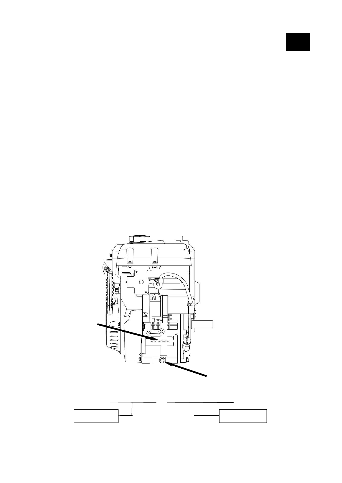
Engine Model and
Serial Numbers
Engine Model
Serial Number
Oil Drain
Service Rules
Engine Model / Serial Number Location
The engine model and serial number are stamped into the crankcase, above the oil drain.
XXX-XXXX XXXXXXXXXXX
3
Page 8

Item
Fastener Size
Torque
Specification
Cylinder Head Bolts
M10
35 ft-lbs (48 Nm)
Connecting Rod Bolts
M8
14 ft-lbs (19Nm)
Flywheel Nut
M16
80 ft-lbs (109 Nm)
Valve Adjust Lock Nut
M6
11 ft-lbs (15 Nm)
Rocker Arm Studs
M8
22 ft-lbs (30 Nm)
Crankcase Cover Bolts
M8
22 ft-lbs (30 Nm)
Exhaust Studs
M8
6 ft-lbs (8 Nm)
Exhaust Pipe Nuts
M8
22 ft-lbs (30 Nm)
Air Cleaner Nuts
M6
7.5 ft-lbs (10 Nm)
Oil Drain Plug
M10
17 ft-lbs (23 Nm)
Oil Drain Tube
M12
22 ft-lbs (30 Nm)
Fuel Shut-off Knob Screws
M4
18 in-lbs (2 Nm)
Switch box screw
M4
12 in-lbs (1.5 Nm)
Valve Cover Bolts
M6
7 ft-lbs (10 Nm)
Start Motor Mounting Bolts
M8
19 ft-lbs (26 Nm)
Spark Plug
-
22 ft-lbs (30 Nm)
Fuel Drain Screw
M6
7.5 ft-lbs (10 Nm)
Standard Torque Values
M5 Bolt / Nut
4.5 ft-lbs (6 Nm)
M6 Bolt / Nut
7.5 ft-lbs (10 Nm)
M8 Bolt / Nut
19 ft-lbs (26 Nm)
M10 Bolt / Nut
28 ft-lbs (38 Nm)
M12 Bolt / Nut
41 ft-lbs (55 Nm)
Engine Fastener Torque Specifications
4
Page 9
MODEL
265cc / LC175FDS
302cc / LC180FDS
Engine Type
OHV Single Cylinder, Four Stroke, Forced Air Cooling
Displacement (cc)
265
302
Bore × Stroke (mm)
75×60
80×60
Compression Ratio
8.2:1
8.9:1
Dry Weight
66.1 lbs. (30Kg)
70.5 lbs. (32Kg)
Engine Idle RPM
1700 - 2000 RPM
Engine Operating RPM
3200 – 3400 RPM
Oil Capacity
30 - 32 oz. (0.89 - 0.95 l)
Fuel Type
Unleaded Gasoline, 87 Octane
Fuel Capacity
1.05 Gallons (4l)
Engine Rotation
Counter-clockwise (from P.T.O. side)
Ignition System
T.C.I Transistorized Magneto
Lubrication System
Splash
Starting System
Recoil and Electric
Cylinder
Aluminum with Cast Iron Bore
70.57 lbs. (32Kg)
1
General Specifications
5
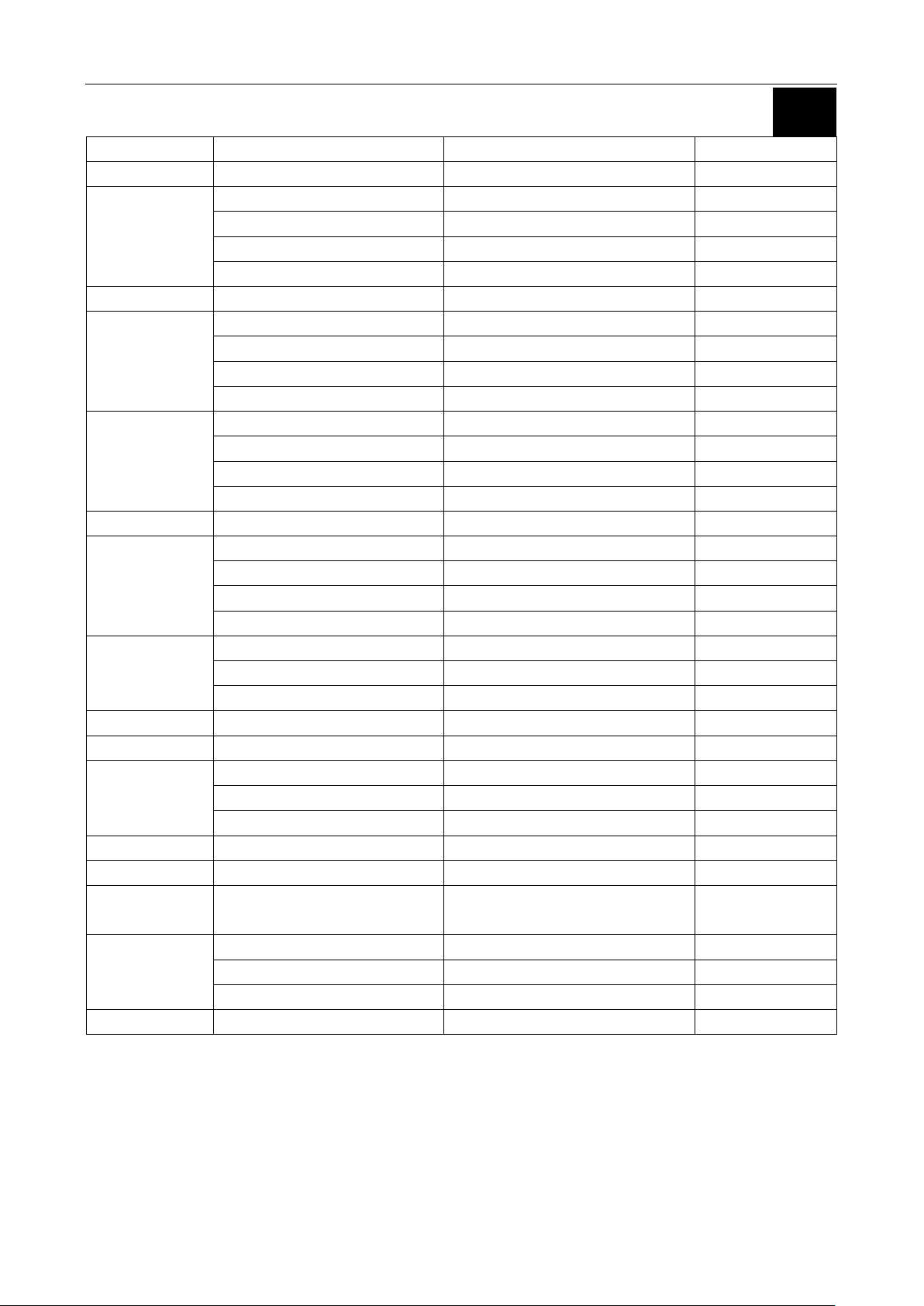
Page 10
Part
Item
Standard
Service Limit
Cylinder
Sleeve Inside Diameter
2.953 - 2.954” (75.015-75.025 mm)
2.959” (75.17 mm)
Piston
Skirt Outside Diameter
2.951 - 2.952” (74.970-74.980 mm)
2.939” (74.65 mm)
Clearance to Cylinder
0.00059 - 0.002” (0.015-0.052 mm)
0.0047” (0.12 mm)
Piston Pin Bore Inside Diameter
0.7087 - 0.7089” (18.002-18.008 mm)
0.7103” (18.042 mm)
Piston Pin Clearance
0.000078 - 0.00055” (0.002-0.014mm)
0.0031” (0.08 mm)
Piston Pin
Outside Diameter
0.7083 - 0.7085” (17.992-17.998 mm)
0.7067” (17.95 mm)
Piston Rings
Ring To Groove (Top and Middle)
0.00059 - 0.00177” (0.015-0.045 mm)
0.0059” (0.15 mm)
End Gap (Top and Middle)
0.0079 - 0.0157” (0.2-0.4 mm)
0.0394”(1.0 mm)
End Gap (Oil Ring)
0.0079 - 0.0275” (0.2-0.7 mm)
0.0394” (1.0 mm)
Width (Top and Middle)
0.077 - 0.078” (1.97-1.99 mm)
0.069” (1.75 mm)
Connecting Rod
Small End Inside Diameter
0.7088 - 0.7093” (18.006-18.017 mm)
0.7114” (18.07 mm)
Big End Inside Diameter
1.3 - 1.3003” (33.02-33.03 mm)
1.3019” (33.07 mm)
Big End Oil Clearance
0.00157 - 0.00259” (0.04-0.066 mm)
0.00472” (0.12 mm)
Big End Side Clearance
0.0039 - 0.0275” (0.1-0.7 mm)
0.0394” (1.0 mm)
Crankshaft
Crankpin Outside Diameter
1.2979” - 1.2984” (32.966-32.981 mm)
1.296” (32.92 mm)
Valves
Clearance (cold) (intake)
0.0059” (0.15 mm)
-
Clearance (cold) (exhaust)
0.0078” (0.20 mm)
-
Stem Diameter (intake)
0.258 - 0.259” (6.565-6.580 mm)
0.2535” (6.44 mm)
Stem Diameter (exhaust)
0.2576 - 0.2582” (6.545-6.560 mm)
0.252” (6.40 mm)
Valve Guides
Inside Diameter (intake, exhaust)
0.2598 - 0.2604” (6.60-6.615 mm)
0.2624” (6.66 mm)
Stem to Guide Clearance (intake)
0.00039 - 0.00145” (0.01-0.037 mm)
0.000393” (0.10 mm)
Stem to Guide Clearance (exhaust)
0.00197 - 0.00303” (0.05-0.077 mm)
0.0047” (0.12 mm)
Valve Seats
Seat Width
0.0315 - 0.0394” (0.8-1.0 mm)
0.0787” (2.0 mm)
Valve Springs
Free Length
1.535” (39 mm)
1.476” (37.5 mm)
Camshaft
Height (intake)
1.2455 - 1.2501” (31.636-31.754 mm)
1.234” (31.35 mm)
Height (exhaust)
1.2470 - 1.2533” (31.674 -31.834 mm)
1.2342” (31.35 mm)
Outside Diameter (bearing)
0.6285 - 0.6292” (15.966-15.984 mm)
0.6267” (15.92 mm)
Crankcase Cover
Camshaft Hole Diameter
0.6299 - 0.6306” (16.0-16.018 mm)
0.6318” (16.05 mm)
Spark Plug
Gap
0.0275 - 0.0314” (0.7-0.8 mm)
-
Stator
(12V-37.5W)
Resistance
0.21-0.31Ω
-
Ignition Coil
Resistance (primary)
1.0-1.6Ω
-
Resistance (secondary)
10.5 KΩ +/- 15%
-
Gap to Flywheel
0.011- 0.019” (.3-.5 mm)
-
Carburetor
Float Height
0.539” (13.7mm)
Engine Specifications - 265cc / 175FDS
6
Page 11
Part
Item
Standard
Service Limit
Cylinder
Sleeve Inside Diameter
3.4651 - 3.4655” (80.015-80.025 mm)
3.4712” (80.17 mm)
Piston
Skirt Outside Diameter
3.1484 - 3.1488” (79.97-79.98 mm)
3.1437” (79.85 mm)
Clearance to Cylinder
0.00059 - 0.002” (0.015-0.052 mm)
0.0047” (0.12 mm)
Piston Pin Bore Inside Diameter
0.7087 - 0.7089” (18.002-18.008 mm)
0.7103” (18.042 mm)
Piston Pin Clearance
0.000078 - 0.00055” (0.002-0.014mm)
0.0031” (0.08 mm)
Piston Pin
Outside Diameter
0.7083 - 0.7085” (17.992-17.998 mm)
0.7067” (17.95 mm)
Piston Rings
Ring To Groove (Top and Middle)
0.00059 - 0.00177” (0.015-0.045 mm)
0.0059” (0.15 mm)
End Gap (Top and Middle)
0.0079 - 0.0157” (0.2-0.4 mm)
0.0394”(1.0 mm)
End Gap (Oil Ring)
0.0079 - 0.0275” (0.2-0.7 mm)
0.0394” (1.0 mm)
Width (Top and Middle)
0.077 - 0.078” (1.97-1.99 mm)
0.069” (1.75 mm)
Connecting Rod
Small End Inside Diameter
0.7088 - 0.7093” (18.006-18.017 mm)
0.7114” (18.07 mm)
Big End Inside Diameter
1.3 - 1.3003” (33.02-33.03 mm)
1.3019” (33.07 mm)
Big End Oil Clearance
0.00157 - 0.00259” (0.04-0.066 mm)
0.00472” (0.12 mm)
Big End Side Clearance
0.0039 - 0.0275” (0.1-0.7 mm)
0.0394” (1.0 mm)
Crankshaft
Crankpin Outside Diameter
1.2979” - 1.2984” (32.966-32.981 mm)
1.296” (32.92 mm)
Valves
Clearance (cold) (intake)
0.0059” (0.15 mm)
-
Clearance (cold) (exhaust)
0.0078” (0.20 mm)
-
Stem Diameter (intake)
0.258 - 0.259” (6.565-6.580 mm)
0.2535” (6.44 mm)
Stem Diameter (exhaust)
0.2576 - 0.2582” (6.545-6.560 mm)
0.252” (6.40 mm)
Valve Guides
Inside Diameter (intake, exhaust)
0.2598 - 0.2604” (6.60-6.615 mm)
0.2624” (6.66 mm)
Stem to Guide Clearance (intake)
0.00039 - 0.00145” (0.01-0.037 mm)
0.000393” (0.10 mm)
Stem to Guide Clearance (exhaust)
0.00197 - 0.00303” (0.05-0.077 mm)
0.0047” (0.12 mm)
Valve Seats
Seat Width
0.0315 - 0.0394” (0.8-1.0 mm)
0.0787” (2.0 mm)
Valve Springs
Free Length
1.535” (39 mm)
1.476” (37.5 mm)
Camshaft
Height (intake)
1.257 - 1.264” (31.953-32.113 mm)
1.244” (31.60 mm)
Height (exhaust)
1.246 - 1.253” (31.66 -31.82 mm)
1.232” (31.30 mm)
Outside Diameter (bearing)
0.6285 - 0.6292” (15.966-15.984 mm)
0.6267” (15.92 mm)
Crankcase Cover
Camshaft Hole Diameter
0.6299 - 0.6306” (16.0-16.018 mm)
0.6318” (16.05 mm)
Spark Plug
Gap
0.0275 - 0.0314” (0.7-0.8 mm)
-
Stator
(12V-37.5W)
Resistance
0.21-0.31Ω
-
Ignition Coils
resistance (primary)
1.0-1.6Ω
-
resistance (secondary)
10.5 KΩ +/- 15%
-
gap to flywheel
0.011- 0.019” (.3-.5 mm)
-
Carburetor
Float Height
0.539” (13.7mm)
1
Engine Specifications - 302cc / 180FDS
7
Page 12

Troubleshooting
Hard Starting / Poor Running
- Incorrect Fuel (Level, Age, Octane, Ethanol Content)
- Fuel System Contamination and / or Carburetor Debris
- Primer System Incorrect Function
- Incorrect Oil Level
- Spark Plug (Incorrect Gap, Fouled, Loose or Faulty)
- Air Intake Restriction
- Air Intake System Leaks
- Ignition Coil to Flywheel Gap Incorrect
- Weak / No Spark
- Choke / Linkage
- Operating RPM Incorrect
- Governor Adjustment Incorrect
- Engine Valve Clearance out of Specification
- Low Compression or Excessive Leakdown
Overheating
- Incorrect Oil Level
- Cylinder Head Gasket Leak
- Debris Build-Up Restricting Air Flow
8
Page 13

1
2
Chapter 2 - Engine Service / Maintenance
Engine Oil Change Procedure 10
Spark Plug Service 11
Valve Clearance Inspection and Adjustment 12
Engine Governor – Zero Point Setting 13
Engine Idle Speed 14
Fuel Filter Replacement 15
9
Page 14
A
B
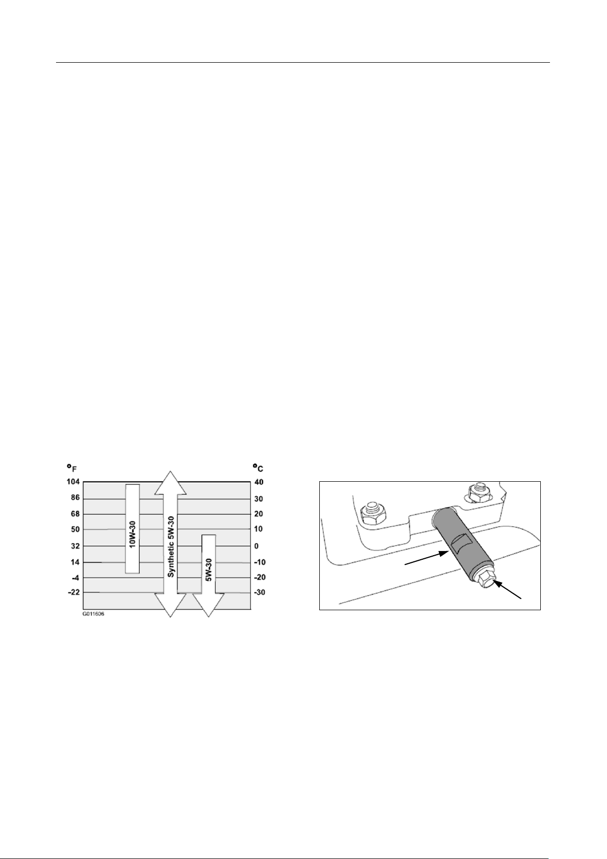
Engine Oil Change Procedure
1. Run engine to warm engine oil.
2. Remove the ignition key.
3. Remove oil dipstick.
4. Position oil drain pan under oil drain plug.
5. Firmly hold the oil drain tube (A) in position. Remove the oil drain plug (B).
6. Completely drain the engine oil.
7. Firmly hold the oil drain tube (A) in position. Install the oil drain plug (B) - torque to 17 ft-lbs (23 Nm).
8. Add oil through the dipstick tube. Wipe the dipstick clean and fully insert it into the dipstick tube.
9. Remove the dipstick and check the oil level – Add oil if needed until the proper oil level is reached
NOTE: DO NOT overfill the engine oil
10. Fully install the dipstick.
11. Properly dispose of the used engine oil.
Engine Oil Capacity:
30 to 32 oz. (0.89 to 0.95 l)
Engine Oil Type:
API classification of SF,SG, SH, SJ, SL, or higher.
10
Page 15
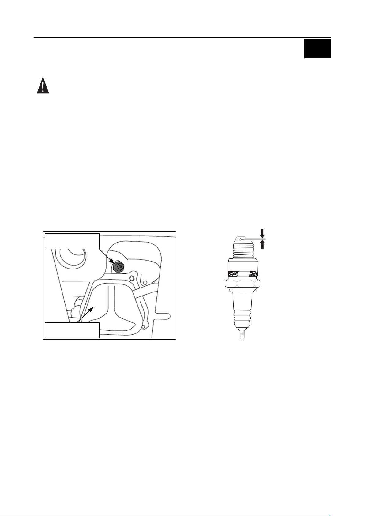
0.0275 - 0.0314”
(0.7-0.8 mm)
2
Valve Cover
Spark Plug
Spark Plug Service
NOTE: Spark plugs of the wrong size or incorrect heat range can cause severe engine damage.
High Voltage Ignition Systems can be Dangerous - Use Caution when Servicing Ignition Systems
1. Disconnect the spark plug boot and thoroughly clean the spark plug area.
2. Remove the spark plug from the engine.
3. Inspect the spark plug for excessively worn electrodes, chips or cracks in the insulator, or excessive
deposits.
4. Measure the electrode gap and adjust if necessary. Spark Plug Gap: 0.0275 - 0.0314” (0.7-0.8 mm)
5. Install spark plug and torque to specification - 22 ft-lbs (30 Nm).
6. Fully install the spark plug boot on the plug.
11
Page 16

Feeler Gauge
Rocker Arm
Pivot Lock Nut
Rocker Arm Pivot
Valve Clearance Inspection and Adjustment
NOTE: Valve clearance inspection and adjustment must be done with the engine cold.
1. Rotate engine to TDC (top-dead-center) of the compression stroke.
2. Remove the valve cover. Be sure both valves are completely closed and the decompression arm is not
holding the valve open.
3. Measure the clearance between the rocker arm and the valve stem with a feeler gauge.
Intake: 0.0059” (0.15 mm)
Exhaust: 0.0078” (0.20 mm)
4. To adjust valve clearance:
- Hold the rocker arm pivot and loosen the pivot lock nut.
- Turn the rocker arm pivot to obtain the specified clearance.
- Hold the rocker arm pivot and tighten the pivot lock nut to specification - 11 ft-lbs (15 Nm).
5. Recheck the clearance and readjust if necessary.
6. Inspect the valve cover gasket and replace if necessary. Install the cylinder head cover and torque
fasteners to specification - 7.5 ft-lbs (10 Nm).
12
Page 17

Governor Arm
Shaft
Governor Arm
Pinch Bolt and Nut
Governor Rod
Throttle Limit Screw
Carburetor
Governor Spring
Throttle Return Spring
2
Engine Governor – Zero Point Setting
1. Remove the front and rear panel to gain access to the governor arm and throttle limit screw.
2. Loosen but do not remove the governor arm pinch bolt and nut.
3. Move the governor arm away the carburetor to fully open the throttle valve. Firmly hold the governor arm
in this position.
4. Rotate the governor arm shaft fully counterclockwise and secure it in this position with a pair of pliers.
5. Tighten the governor arm pinch bolt and nut to Specification - 7.5 ft-lbs (10 Nm).
6. Start and warm engine.
7. Run Engine at MAX RPM. Adjust throttle limit screw until MAX engine speed is set to 3200 – 3400 RPM.
8. Verify engine idle speed is 1700 - 2000 RPM and adjust if necessary.
9. Verify that the governor arm and throttle valve move freely.
NOTE: The Illustration below has additional parts removed to show governor linkage detail.
13
Page 18

A
Valve Cover
Stop Screw
Engine Idle Speed
1. Start the engine and allow it to warm to normal operating temperature.
2. With the engine at low idle, just before the kill switch is activated, adjust the throttle stop screw to achieve
the recommended engine idle speed.
Recommended Idle Speed: 1700 - 2000 RPM
14
Page 19

2
A
Fuel Filter
Fuel Filter and Hose Replacement
- Fuel is Extremely Flammable - Use Extreme Caution When Servicing Fuel System
1. Drain the fuel tank into an approved container.
NOTE: Ensure fuel system contains no fuel to prevent leak when the fuel filter is replaced.
2. Release the fuel filter / fuel hose clamps (A) and slide them away from the fittings.
3. Remove the fuel filter / hose asm. from the engine.
4. Properly install new fuel filter / hose asm. and clamps (A).
5. Re-fill tank with fresh fuel.
6. Verify hose routing and check for leaks.
7. Properly dispose of any unused fuel.
15
Page 20

NOTES:
16
Page 21

3
Chapter 3 - Engine Disassembly and Service
Engine Service – Upper End 18-31
Heater Box Exploded View 18
Carburetor Mounting 19
Carburetor Exploded View 20
Fuel Tank / Engine Cover / Rear Panel Exploded View 21
Engine Cover / Front Panel / Fuel Tank / Fuel Hose View 22
Muffler / Heat Shield Exploded View 23
Governor and Throttle Control Exploded View 24
Recoil Asm. Exploded View 25
Starter / Flywheel / Coil Exploded View 26
Cylinder Head Exploded View and Service Information 27
Cylinder Head / Valves Exploded View and Service Information 28
Valve Spring / Cylinder Head Specifications 29
Valve Stem and Guide Specifications 30
Valve Seat Reconditioning 31
Engine Service – Lower End 32-40
Crankcase Exploded View and Information 32
Governor Exploded View 33
Piston / Connecting Rod Exploded View and Information 34
Crankcase / Camshaft Timing 35
Bearing / Piston Pin / Cylinder ID Specifications 36
Piston / Piston Ring Specifications 37
Piston Ring / Connecting Rod Specifications 38
Crankshaft Specifications 39
Camshaft and Crankcase Cover Specifications 40
17
Page 22

Gasket
Heater Box Cover
Heater Box Insert
Primer Bulb
Carburetor Mounting Nuts
7 ft-lbs (10 Nm)
Ignition Switch and Key
Engine Service – Upper End
Heater Box Exploded View
18
Page 23

Note spacer orientation for installation
Carburetor Removal:
-Remove throttle return spring
from throttle shaft
-Pull Carburetor outward
-Align governor rod with notch
in throttle shaft
-Remove governor rod
and remove carburetor
Throttle
Shaft
Throttle
Return spring
Governor Rod
Notch
Fuel Hose
Governor Rod
Throttle Return Spring
Gasket
Spacer
Primer Asm.
3
Carburetor Mounting
19
Page 24

Gasket
Gasket
Gasket
Float Pin
Needle Asm.
Float
Main Jet and Nozzle
Primer Asm.
Primer Hose
Choke Lever Asm.
Jet
O ring
Throttle Stop
Screw
7 ft-lbs (10 Nm)
Float Bowl
Carburetor Exploded View
20
Page 25

Fuel Tank
Mounting Hardware
7 ft-lbs (10 Nm)
Fuel Tank
Mounting Hardware
7 ft-lbs (10 Nm)
Rear Panel
7 ft-lbs (10 Nm)
19 ft-lbs (26 Nm)
Clip
Fuel Tank Cover
Fuel Tank
Dip Stick
3
Fuel Tank / Engine Cover / Rear Panel Exploded View
21
Page 26

Fuel Tank
Mounting Bracket
19 ft-lbs (26 Nm)
Starter Switch
Bracket
7 ft-lbs (10 Nm)
Fuel Filter
Fuel Hose
Fuel Hose
and Sleeve
Fuel Shut
Off Valve
7 ft-lbs
(10 Nm)
Front
Panel
18 in-lbs (2 Nm)
7 ft-lbs (10 Nm)
7 ft-lbs (10 Nm)
Engine Cover / Front Panel / Fuel Tank / Fuel Hose Exploded View
22
Page 27

Muffler Shield
19 ft-lbs (26 Nm)
Muffler Protector
Muffler
7 ft-lbs (10 Nm)
22 ft-lbs (30 Nm)
Exhaust Pipe
Gasket
7 ft-lbs (10 Nm)
3
Muffler / Heat Shield Exploded View
23
Page 28

7 ft-lbs (10 Nm)
Pinch Bolt
Governor Arm
Governor Rod
Throttle Return Spring
Governor Spring
Engine Kill Switch
7 ft-lbs (10 Nm)
Throttle Limit
Screw
Throttle Control Asm.
Governor and Throttle Control Asm. Exploded View
24
Page 29

Upper Heat Shroud
7 ft-lbs (10 Nm)
Shroud and Recoil Asm.
7 ft-lbs (10 Nm)
7 ft-lbs (10 Nm)
Set Screw
Guide
Clip
Spring
Recoil
Asm.
Ratchet
Spring
Reel
Rope
3
Recoil Asm. Exploded View
25
Page 30

Starter Asm.
12 in-lbs (1.5 Nm)
Flywheel
80 ft-lbs (109 Nm)
7 ft-lbs (10 Nm)
Ignition Coil Asm.
Stator
7 ft-lbs (10 Nm)
Rubber Grommet
Fan
Cup
Starter / Flywheel / Coil Exploded View
26
Page 31
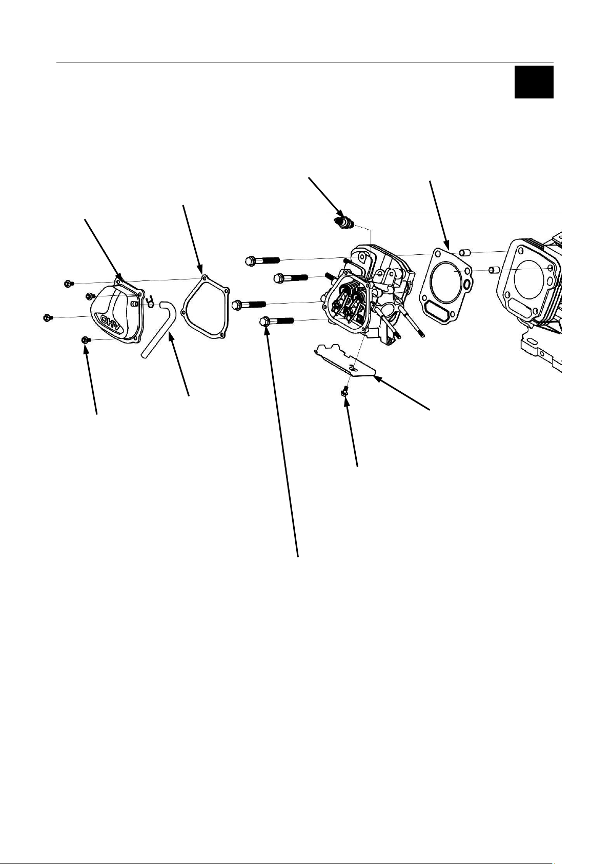
Valve Cover
7 ft-lbs (10 Nm)
Gasket
Breather
Tube
Spark Plug
22 ft-lbs (30 Nm)
Gasket
7 ft-lbs (10 Nm)
Shroud
Cylinder Head Bolt Torque Sequence:
1. Initially Torque the (4) Cylinder Head Bolts in a Crisscross Pattern to 10 ft-lbs (14 Nm).
2. Evenly Torque the (4) Cylinder Head Bolts in a Crisscross Pattern to 35 ft-lbs (48 Nm).
3
Cylinder Head Exploded View and Service Information
27
Page 32

Exhaust Valve
Intake Valve
Push Rod
Guide Plate
Studs
23 ft-lbs (31 Nm)
Rocker Arm
Pivot
Pivot Lock Nut
11 ft-lbs (15 Nm)
Valve Keeper
Rotator
Retainer
Valve Spring
Spring Seat
Seal
Cylinder Head / Valves Exploded View and Service Information
28
Page 33

Standard
Service Limit
1.535” (39 mm)
1.476” (37.5 mm)
Standard
Service Limit
0.03149 - 0.0393”
(0.8-1.0 mm)
0.0591”
(1.5 mm)
Service Limit
0.00393” (0.10 mm)
STRAIGHT EDGE
FEELER GAUGE
3
Valve Spring Free Length Specification
Valve Seat Width Inspection
Remove carbon deposits from the combustion
chamber. Inspect the valve seats for pitting or
other damage.
Cylinder Head Warp Inspection
- Remove carbon deposits from the combustion
chamber.
- Clean off any gasket material from the
cylinder head surface.
- Check the spark plug hole and valve areas for cracks.
- Check the cylinder head for warpage with a straight
edge and a feeler gauge as shown.
29
Page 34

Standard
Service Limit
Intake
0.2584 - 0.2590”
(6.565-6.58 mm)
0.2535”
(6.44 mm)
Exhaust
0.2577 - 0.2583”
(6.545-6.56 mm)
0.252”
(6.40 mm)
Standard
Service Limit
0.2598 - 0.2604”
(6.60-6.615 mm)
0.2624”
(6.66 mm)
Standard
Service Limit
Intake
0.00039 - 0.00145”
(0.01-0.037 mm)
0.000393”
(0.10 mm)
Exhaust
0.00197 - 0.00303”
(0.05-0.077 mm)
0.0047”
(0.12 mm)
Valve Stem Inspection
Inspect each valve for face irregularities, bending
or abnormal wear.
Valve Stem Diameter Specification
Valve Guide Inspection
Ream the exhaust valve guide to remove any carbon deposits before measuring.
Valve Guide ID Specification:
Valve Stem to Guide Clearance
Subtract each valve stem OD from the corresponding guide ID to
obtain the guide-to-stem clearance.
30
Page 35

Standard
Service Limit
0.0315 - 0.0394”
(0.8-1.0 mm)
0.0787”
(2.0 mm)
CONTACT TOO LOW
CONTACT TOO HIGH
3
Valve Seat Reconditioning
1. Thoroughly clean the combustion chamber and valve seats to remove carbon deposits.
2. Apply a light coat of Prussian Blue or erasable felt-tipped marker ink to the valve faces.
3. Properly install valves, springs and keepers. Manually open the valves, then and snap them closed
against their seats several times. Be sure the valves do not rotate on the seat. Remove the valve
assemblies. The transferred marking compound will show any area of the seat that is not concentric.
4. Use a 45°cutter to remove enough material to produce a smooth and concentric seat. Follow the valve
seat cutter manufacture’s instructions. Turn the cutter clockwise, never counterclockwise. Continue to
turn the cutter as you lift it from the valve seat.
5. Use a 30°~32° and 60° cutter to narrow and adjust the valve seat so that it contacts the middle of the
valve face. The 30°~32° cutter removes material from the top edge. The 60° cutter removes material from
the bottom edge. Be sure that the width of the finished valve seat is within specification.
6. Lap valves in accordance with valve lapping kit instructions.
7. Clean valve and seat of all lapping compound.
Valve Seat Width
31
Page 36

Bearing
Seal
Crankcase Cover
Governor
Gasket
Valve Tappets
Camshaft
Triangular Mark to Face Down
Piston Asm.
Rod Cap
Crankshaft
Governor
Drive Gear
Seal
14 ft-lbs (19Nm)
17 ft-lbs (23 Nm)
17 ft-lbs (23
22 ft-lbs (30 Nm)
22 ft-lbs
(30 Nm)
Torque in a
Crisscross Pattern
Engine Service – Lower End
Crankcase Exploded View and Service Information
32
Page 37

Crankcase
Shaft
Washer
Clip
Governor Gear
Pin
Weight
Slider
Pin
Washer
Governor
Shaft
3
Governor Exploded View
33
Page 38

Point Down to
Match Piston Arrow
Top Ring / Gap
Second Ring / Gap
Oil Rings
Stagger Scraper Rings
150°~ 210° from the Oil Ring
Install Piston Ring with
Markings “UP”
Triangular Mark to Face “DOWN”
Towards Push Rods
Oil Splash Spoon
Connecting Rod
Piston Pin Clip
Piston Rotation Arrow
Piston Pin
Clip Gap
Piston Cut-out
Piston / Connecting Rod Exploded View and Service Information
34
Page 39

3
Timing Marks
Crankshaft
Camshaft
Crankshaft / Camshaft Timing
35
Page 40

Standard
Service Limit
0.7083 - 0.7085”
(17.992-17.998 mm)
0.7067”
(17.95 mm)
Engine
Standard
Service Limit
175FDS-1
2.953 - 2.954”
(75.015-75.025 mm)
2.959”
(75.17 mm)
180FDS-1
3.4651 - 3.4655”
(80.015-80.025 mm)
3.4712”
(80.17 mm)
Crankshaft Bearing Free Play
1. Clean the bearing in solvent and dry it.
2. Spin the bearing by hand and check for play.
Replace the bearing if it is noisy or has excessive free play.
Piston Pin OD
Cylinder Inside Diameter
Inspect cylinder inside diameter for taper and out of round with a bore gauge.
Measure in two different directions, front to back and side to side, on
three different levels (½”down from the top, middle and ½” up from the
bottom).
36
Page 41

Engine
Standard
Service Limit
175FDS-1
2.951 - 2.952”
(74.970-74.980 mm)
2.939”
(74.65 mm)
180FDS-1
3.1484 - 3.1488”
(79.97-79.98 mm)
3.1437”
(79.85 mm)
Engine
Standard
Service Limit
175FDS-1
180FDS-1
0.00059 - 0.002”
(0.015-0.052 mm)
0.0047”
(0.12 mm)
Engine
Standard
Service Limit
175FDS-1
180FDS-1
Top /
Middle
Rings
0.00059 - 0.00177”
(0.015-0.045 mm)
0.0059”
(0.15 mm)
Engine
Standard
Service Limit
175FDS-1
180FDS-1
Top /
Middle
Rings
0.077 - 0.078”
(1.97-1.99 mm)
0.069”
(1.75 mm)
3
Piston Skirt Outside Diameter
Measure and the piston skirt outside diameter
10mm from the skirt base and 90°to piston pin hole.
Piston to Cylinder Clearance Specification
Piston Ring to Groove Clearance
Piston Ring Width
37
Page 42

Engine
Standard
Service Limit
175FDS-1
180FDS-1
0.0079 - 0.0157”
(0.2-0.4 mm)
0.0394”
(1.0 mm)
Engine
Standard
Service Limit
175FDS-1
180FDS-1
0.0079 - 0.0275”
(0.2-0.7 mm)
0.0394”
(1.0 mm)
Engine
Standard
Service Limit
175FDS-1
180FDS-1
0.7088 - 0.7093”
(18.006-18.017 mm)
0.7114”
(18.07 mm)
Engine
Standard
Service Limit
175FDS-1
180FDS-1
1.3 - 1.3003”
(33.02-33.03 mm)
1.3019”
(33.07 mm)
Piston Ring End Gap
Top and Middle Rings
Oil Ring
Use the piston to position the rings squarely 1” down from the top of the cylinder.
Connecting Rod Small End ID
.
Connecting Rod Big End ID
38
Page 43

Engine
Standard
Service Limit
175FDS-1
180FDS-1
1.2979” - 1.2984”
(32.966-32.981 mm)
1.296”
(32.92 mm)
Engine
Standard
Service Limit
175FDS-1
180FDS-1
0.0039 - 0.0275”
(0.1-0.7 mm)
0.0394”
(1.0 mm)
Engine
Standard
Service Limit
175FDS-1
180FDS-1
0.00157 - 0.00259”
(0.04-0.066 mm)
0.00472”
(0.12 mm)
3
Crankshaft Pin Outside Diameter
Connecting Rod Big End Side Clearance
Connecting Rod Big End Oil Clearance
- Clean oil from the crankshaft and connecting rod.
- Use plastic gauge style measuring tool in accordance
to the manufactures instructions to measure the oil clearance.
Connecting Rod Bolt Torque: 14 ft-lbs (19Nm)
39
Page 44

Engine
Standard
Service Limit
175FDS-1
1.2455 - 1.2501”
(31.636-31.754 mm)
1.2342”
(31.35 mm)
180FDS-1
1.257 - 1.264”
(31.953-32.113 mm)
1.244”
(31.60 mm)
Engine
Standard
Service Limit
175FDS-1
1.2470 - 1.2533”
(31.674 -31.834 mm)
1.2342”
(31.35 mm)
180FDS-1
1.246 - 1.253”
(31.66 -31.82 mm)
1.232”
(31.30 mm)
Engine
Standard
Service Limit
175FDS-1
180FDS-1
0.6285 - 0.6292”
(15.966-15.984 mm)
0.6267”
(15.92 mm)
Engine
Standard
Service Limit
175FDS-1
180FDS-1
0.6299 - 0.6306”
(16.0-16.018 mm)
0.6318”
(16.05 mm)
Camshaft Lobe Height Specifications
Intake
Exhaust
Camshaft Journal Outside Diameter
Check the camshaft bearing journal for scoring, wear or damage.
NOTE: Verify that the decompression mechanism moves freely.
.
Crankcase Cover / Camshaft Hole Inside Diameter
40
Page 45

4
Chapter 4 – Electrical System Information
Ignition Coil Gap Adjustment 42
Ignition Coil Resistance Inspection 42
Spark Testing 43
Stator Resistance Test 43
41
Page 46

Ignition Coil Gap
0.011- 0.019”
(.3-.5 mm)
A - Primary Coil Resistance
1.0-1.6 Ω
B - Secondary Coil Resistance
10.5 KΩ +/- 15%
A
B
Ignition Coil Gap Adjustment
High Voltage Ignition Systems can be Dangerous - Use Caution when Servicing Ignition Systems
1. Install the ignition coil and lightly tighten the igniting coil mounting bolts.
2. Rotate engine so ignition coil is aligned with the magnet portion of the flywheel.
3. Insert the feeler gauge between the flywheel and coil.
4. Adjust the ignition coil gap at both side of the coil.
5. Sufficiently tighten the mounting bolts.
Ignition Coil Resistance Inspection
Primary Coil
Place Ohm meter leads between the harness connection
lead and the exposed metal coil leg.
Secondary Coil
Place Ohm meter leads between exposed metal coil leg
and the spark plug terminal connection.
42
Page 47

Resistance
0.21-0.31Ω
4
Spark Testing
- Fuel is Extremely Flammable - Use Extreme Caution When Servicing the Fuel System
- High Voltage Ignition Systems can be Dangerous - Use Caution when Servicing Ignition Systems
1. Remove spark plug cap from the spark plug.
2. Remove the spark plug from the engine.
3. Connect the negative (-) electrode of the spark plug (threaded area) to ground (cylinder head cover).
4. Crank the engine and view the electrode gap. Spark should be present when engine is turning over.
5. Reinstall the spark plug and torque to specification - 22 ft-lbs (30 Nm).
6. Properly install the spark plug cap
Stator Resistance Test
Measure resistance between lead wire terminals as shown.
43
Page 48

RESIDENTIAL PRODUCTS
Form Number: 492-9235
44
 Loading...