

Page 1

FormNo.3368-615RevA
LawnStriperKit
ModelNo.20601
OperatorManual
Safety
•Readalloftheinstructionsinthismanualpriorto
usingthelawnstriperattachment.
•Thelawnstriperattachestoandfollowsbehindyour
lawnmowerduringnormalgrass-cuttingoperations,
andshouldnotaffecttheoperatingcharacteristicsof
yourmower.Carefullyfollowallofyourlawnmower
manufacturer’soperatinginstructionsandwarnings
whenusingthelawnstriperattachment.
•Thelawnstriperattachmentshouldnot
interferewithnormalmoweroperations,such
ascutting/mulching/bagging.Ifthereisany
interferenceimmediatelyshutoffmower,then
inspectthelawnstriperattachmentinstallation,make
anyadjustmentsneededtocorrecttheproblem,and
reassessoperationstoverifythattheinterferencehas
beenresolved.
•Thelawnstriperattachmentisdesignedtoworkwith
mostwalk-behind,self-propelled,andpush-type
lawnmowers.Donotusewithanyothertypeof
mower.
•Thelawnstriperattachmentmustbeproperly
installed,attached,andadjustedinordertowork
alongwithyourparticularlawnmower.
•Ifthelawnstriperattachmentshouldinterfere
withyourabilitytomowaroundobstructions,
walkways,orothertightlyconstrainedareas,shutoff
themower,removetherollerassembly,andthen
mowaroundtheobstructedareawithouttheroller
assemblyattached.
CAUTION
Donotassemble,disassemble,attach,inspect,or
adjustthelawnstriperattachmentwhilethemower
isrunning.
Shutoffthemowerbeforeperforminganyofthese
actions.
CAUTION
Donotplaceclampsystemoveranytypeofexisting
wires/cablesthatmaybepresentonlawnmower
handlebars.
©2011—TheT oro®Company
8111LyndaleAvenueSouth
Bloomington,MN55420
Registeratwww.Toro.com.
OriginalInstructions(EN)
PrintedintheUSA.
AllRightsReserved
Page 2
Installation
1
InstallingtheClamps
Partsneededforthisprocedure:
4Phillipsscrew
2Panheadscrew
2Innerclamp
2
Outerclamp
2Verticaltube
2Angleadjuster
Procedure
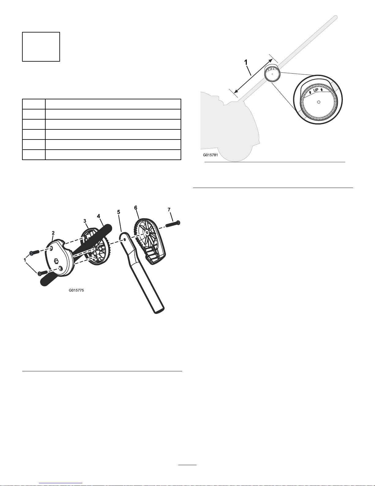
1.Withinthelowerthirdofthehandlebar,placethe
innerclampontheinsideofhandlebar(Figure1).
5
6
4
3
2
1
7
G015775
Figure1
Right-handhandlebarshown
1.Phillipsscrew5.Verticaltube
2.Innerclamp6.Angleadjuster
3.Outerclamp
7.Panheadscrew
4.Mowerhandlebar
2.Placeouterclampontheoutsideofhandlebar,with
thewordUpfacingupward(Figure2),andconnect
thetwoclampstothehandlebarusing2phillips
screws(
Figure1).
Important:Donotfullytightenphillipsscrews
asheightadjustmentswillbemadelater.
1
G015781
Figure2
1.Lowerthirdofmowerhandlebar
3.Settheverticaltubeintotheangleadjuster.Make
surethatthetopportionoftheverticaltuberestsat
ontheinnerportionoftheangleadjuster(
Figure1).
4.Usethepanheadscrewtoattachtheverticaltube
andangleadjustertotheclampassemblyasshown
in
Figure1.
Important:Donotfullytightenpanheadscrew,
asangleadjustmentswillbemadelater.
5.Repeatthisprocessfortheoppositehandlebar.
2
Page 3
2
AssemblingtheHitchTube
andCornerTubes
Partsneededforthisprocedure:
2
Cornertube
1Hitchtube
Procedure
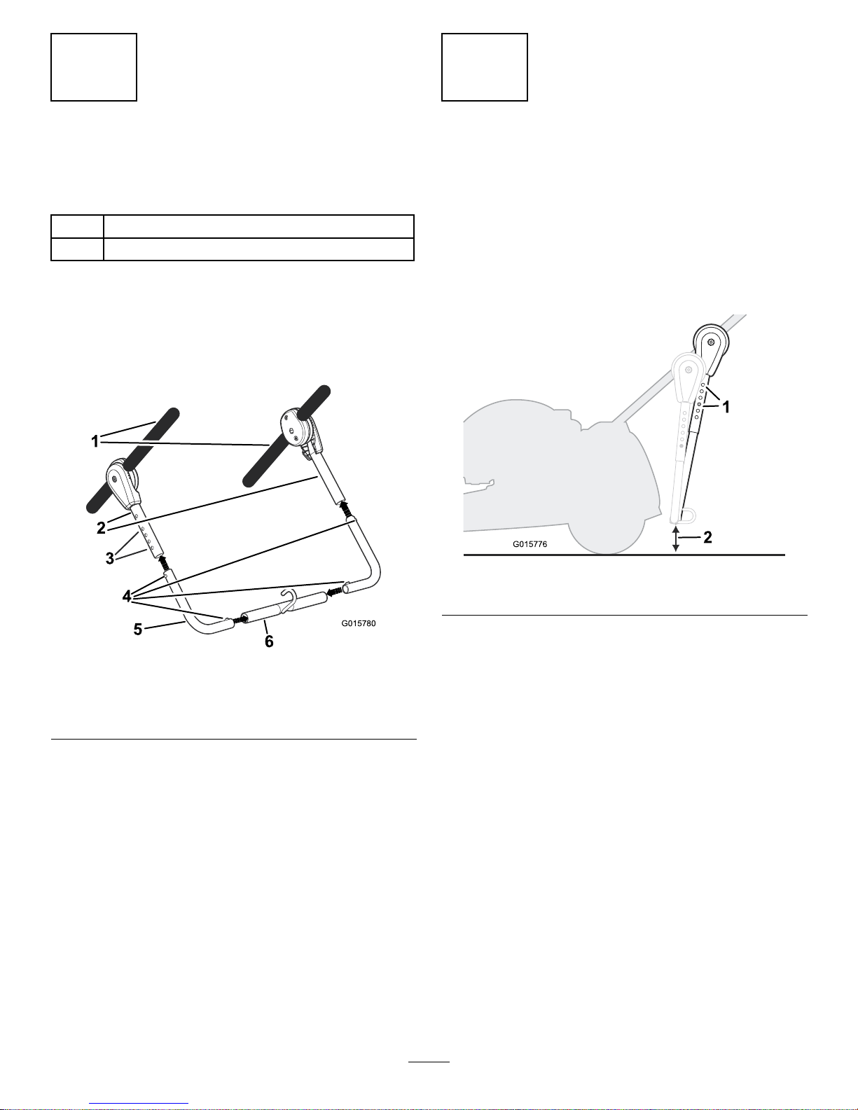
1.Attachcornertubestothehitchtubebypressing
downonthevalcopinsandlockingthemintoplace
inthevalcoholes(
Figure3).
3
4
2
1
5
G015780
6
Figure3
1.Lawnmowerhandlebars4.Valcopins
2.Verticaltubes
5.Cornertube
3.Valcoholes6.Hitchtube
2.Attachthecornertubestotheverticaltubesby
pressingdownonthevalcopinsandlockingthem
intoplaceinthevalcoholes(
Figure3).
Note:Whensettingwidthandheightofthe
assembly,makesurethevalcopinsoneachsideare
inmatchingholesontheoppositeside.
3
AdjustingAngleandHeight
NoPartsRequired
Procedure
1.Angletheassemblyasclosetothemoweraspossible
bymovingtheclampsupordownonthemower
handlebarswithouthittingthemowerorimpeding
themowerbaggingsystem(
Figure4).
1
2
G015776
Figure4
1.Valcohole
2.Minimumof3-1/2inches
2.Fullytightenthe2panheadscrewsand4phillips
screws.
3.Settheheightoftheassemblyusingthevalcopinson
eitherside,makingsuretheassemblyisaminimum
of3-1/2inchesofftheground.
3
Page 4

4
FillingandAttachingRoller
Assembly
Partsneededforthisprocedure:
1Rollerplug
1Rollerassembly
Procedure
1.Filltherollerassemblywithapproximately16to20
lbs.ofsand.
3
2
1
G015779
Figure5
1.Rollerplug3.Rollerassembly
2.Pourdrysandintohere
2.Sealtherollerassemblywithrollerplug(Figure5).
Important:Makesuretherollerplugisfully
tightened.Failuretodosowillresultinroller
plugimpedingtheroller’sabilitytoturn.
3.Attachthesand-lledrollerassemblyontohitchtube
hookasshownin
Figure6.
1
2
G015777
Figure6
1.Hitchtube2.Rollerassembly
4.Verifythattherollerassemblydoesnotinterfere
withanypartofthemower,includingotherkitsor
safetyfeatures.
4
Page 5

Troubleshooting
Problem
PossibleCauseCorrectiveAction
1.Debrisstuckinrollerassembly
1.Turnoffmowerandverify/removeany
debris(bark,twigs,stones)thatare
obstructingtheroller.
2.Rollerplugisnotfullytightened.2.Checktoseethatrollerplugisush
withendcap,andtightenrollerplug
fully.
Rollerdoesnotturn.
3.Rollerassemblyisnotlled.3.Makesuretherollerassemblyislled
withapproximately16to20lbs.of
DRYsand.
1.Lawnstriperisnotattachedcorrectly
1.RefertoOwner’sManualforproper
installation.
2.Grassiscuttooshort.2.Waitforgrasstogrowbeforecutting
withthelawnstriperattached.
Patterningeffectdoesnotshow.
3.Lackofpropersunlight.3.Partial/fullsunlightisoptimal.
1.Assemblyisnotatproperheight.
1.Turnoffthemower,andsetassembly
toproperheightandangleasoutlined
inOwner’sManual.
U-Barassemblyishittingtheground.
2.Heightisdifferentoneithersideof
assembly.
2.Makesurethatheightisthesame
onbothsidesasoutlinedinOwner’s
Manual.
5
Page 6

FormNo.3368-615RevA
Kitderayadodelcésped
Nºdemodelo20601
OperatorManual
Seguridad
•Leatodaslasinstruccionesdeestemanualantesde
utilizarelrodillodecésped.
•ElrodillodecéspeddeToroseacoplaasu
cortacéspedyesarrastradodetrásdurantelasiega
normal,peronodebeafectaralascaracterísticasde
operacióndesucortacésped.Sigacuidadosamente
todaslasinstruccionesdeusoyadvertenciasdel
fabricantedesucortacéspedmientrasutilizael
rodillodecésped.
•Elrodillodecéspednodebeinterferirconlas
operacionesdesieganormales,talescomolasiega,el
mulchingoelensacado.Sihayalgunainterferencia
pareinmediatamenteelmotordelcortacésped,
luegocompruebelainstalacióndelrodillodecésped,
hagalosajustesnecesariosparacorregirelproblema,
yhagaunaspruebasparavericarquelainterferencia
haquedadoresuelta.
•Elrodillodecéspedestádiseñadoparafuncionar
conlamayoríadeloscortacéspedesdirigidos,
autopropulsados,ymanuales.Noloutilicecon
otrostiposdecortacésped.
•Elrodillodecéspeddebeserinstalado,acopladoy
ajustadocorrectamenteparaquefuncioneconsu
modelodecortacésped.
•Sielrodillodecéspedinterereconsucapacidad
parasegaralrededordeobstáculos,caminos,uotros
lugaresestrechos,pareelmotordelcortacésped,
retireelconjuntodelrodilloyluegosieguealrededor
delazonaproblemáticasinteneracopladoel
conjuntodelrodillo.
CUIDADO
Nomonte,desmonte,acople,inspeccioneoajuste
elrodillodecéspedconelmotordelcortacésped
enmarcha.
Pareelmotordelcortacéspedantesderealizar
cualquieradeestasactividades.
CUIDADO
Nocoloqueelmecanismodejaciónsobre
cualquiertipodecablequehubieraenelmanillar
delcortacésped.
©2011—TheT oro®Company
8111LyndaleAvenueSouth
Bloomington,MN55420
Registresuproductoenwww.T oro.com.
Traduccióndeloriginal(ES)
ImpresoenEE.UU.
Reservadostodoslosderechos
Page 7

Instalación
1
Instalacióndelmecanismode
apriete
Piezasnecesariasenestepaso:
4TornilloPhillips
2Tornillodecabezaredonda
2Piezainteriordelaabrazadera
2Tubovertical
2Ajustadordeángulo
Procedimiento
1.Coloquelapiezainteriordelaabrazaderaenel
interiordeltercioinferiordelmanillar(Figura1).
5
6
4
3
2
1
7
G015775
Figura1
Manillarderechoilustrado
1.TornilloPhillips5.Tubovertical
2.Piezainteriordela
abrazadera
6.Ajustadordeángulo
3.Piezaexteriordela
abrazadera
7.Tornillodecabeza
redonda
4.Manillardelcortacésped
2.Coloquelapiezaexteriordelaabrazaderaenel
exteriordelmanillar,conlapalabraUphaciaarriba
(
Figura2),yconectelasdospiezasdelaabrazadera
almanillarcondostornillosPhillips(Figura1).
Importante:Noaprietetotalmentelostornillos
Phillips,porquemásadelanteseránecesario
ajustarlaaltura.
1
G015781
Figura2
1.Tercioinferiordelmanillardelcortacésped
3.Coloqueeltuboverticalenelajustadordeángulo.
Asegúresedequelapartesuperiordeltubovertical
estáplanasobrelaporcióninteriordelajustadorde
ángulo(Figura1).
4.Utiliceeltornillodecabezaredondaparaacoplarel
tuboverticalyelajustadordeánguloalaabrazadera,
segúnsemuestraen
Figura1.
Importante:Noaprietetotalmenteeltornillo
decabezaredonda,porquemásadelanteserá
necesarioajustarelángulo.
5.Repitaesteprocedimientoenelotromanillar.
2
Page 8

2
Montajedeltubodeenganche
ylostubosdeesquina
Piezasnecesariasenestepaso:
2Tubodeesquina
1Tubodeenganche
Procedimiento
1.Conectelostubosdeesquinaaltubodeenganche
presionandolospasadoresdeajustehaciadentroy
bloqueándolosenlosagujeros(
Figura3).
3
4
2
1
5
G015780
6
Figura3
1.Manillardelcortacésped4.Pasadoresdeajuste
2.Tubosverticales5.Tubodeesquina
3.Agujerosdeajuste6.Tubodeenganche
2.Conectelostubosdeesquinaalostubosverticales
presionandolospasadoresdeajustehaciadentroy
bloqueándolosenlosagujeros(
Figura3).
Nota:Alajustarlaanchuraylaalturadelsistema,
asegúresedequelospasadoresdeajusteestánenel
mismoagujeroencadalado.
3
Ajustedelánguloydelaaltura
Nosenecesitanpiezas
Procedimiento
1.Ajusteelconjuntoparaqueestélomáscercaposible
delcortacésped,desplazandolasabrazaderashacia
arribaohaciaabajoenelmanillarsinquelostubos
choquencontraelcortacéspedoestorbenelsistema
deensacado(
Figura4).
1
2
G015776
Figura4
1.Agujerodeajuste
2.Mínimode3,5pulg.(9cm)
2.Aprietedeltodolos2tornillosdecabezaredonda
ylos4tornillosPhillips.
3.Ajustelaalturadelconjuntousandolospasadoresde
ajustedecadalado,asegurándosedequeelconjunto
estáa3,5pulg.(9cm)comomínimodelsuelo.
3
Page 9

4
Llenadoyconexióndelrodillo
Piezasnecesariasenestepaso:
1Tapóndelrodillo
1
Conjuntodelrodillo
Procedimiento
1.Lleneelrodilloconaproximadamente16–20libras
(7,2–9kg)dearena.
3
2
1
G015779
Figura5
1.T apóndelrodillo
3.Conjuntodelrodillo
2.Viertaarenasecaaquí
2.Coloqueeltapónparasellarelrodillo(Figura5).
Importante:Asegúresedequeeltapóndel
rodilloestábienapretado.Sinoestábien
apretado,impediráqueelrodillogire.
3.Conecteelrodillollenodearenaalganchodeltubo
deenganche,segúnsemuestraen
Figura6.
1
2
G015777
Figura6
1.Tubodeenganche
2.Conjuntodelrodillo
4.Compruebequeelconjuntodelrodillonointerere
conningúnelementodelcortacésped,incluyendo
otroskitsyelementosdeseguridad.
4
Page 10

Solucióndeproblemas
ProblemaPosiblecausa
Accióncorrectora
1.Hayresiduosqueobstruyenelrodillo.1.Pareelmotordelcortacéspedy
compruebelapresenciaderesiduos
(corteza,ramitas,piedras,etc.);retire
cualquierresiduodelrodillo.
2.Eltapóndelrodillonoestábien
apretado.
2.Compruebequeeltapóndelrodillo
estáenrasadoconelextremodel
rodillo,yaprieteeltapónafondo.
Elrodillonogira.
3.Elrodillonosehallenado.3.Asegúresedequeelrodilloseha
llenadoconaproximadamente16–20
libras(7,2–9kg)dearenaSECA.
1.Elrodillodecéspednoestá
correctamenteconectado
1.Consulteelprocedimientode
instalacióncorrectoenelManualdel
usuario.
2.Lahierbaestádemasiadocorta.2.Espereaquecrezcalahierba
parasegarconelrodillodecésped
acoplado.
Noseaprecianlasfranjasenelcésped.
3.Faltadeluzsolar.
3.Sevemejorconbuenaluzdelsol.
1.Elconjuntonoestáalaalturacorrecta.1.Pareelmotordelcortacéspedyajuste
correctamentelaalturayelángulo,
segúnloindicadoenelManualdel
usuario.
LabarraenUchocacontraelsuelo.
2.Laalturaesdiferenteencadaladodel
conjunto.
2.Asegúresedequelaalturaeslamisma
enamboslados,segúnloindicadoen
elManualdelusuario.
5
Page 11

FormNo.3368-615RevA
Kittraceur
N°demodèle20601
OperatorManual
Sécurité
•Liseztouteslesinstructionsdecemanuelavant
d'utiliserlerouleautraceur.
•Lerouleautraceursexederrièrelatondeuse
quiletirependantlesopérationsdetonte
habituellesilnedevraitmodierlescaractéristiques
defonctionnementdelatondeuse.Observez
scrupuleusementlesinstructionsd'utilisationdu
fabricantdelatondeuseetlesmisesengardelorsque
vousutilisezlerouleautraceur.
•Lerouleautraceurnedevraitpasgênerles
opérationsnormalesdetonte,commelatonte/le
mulching/leramassage.Encasdeproblème,arrêtez
immédiatementlatondeuse,puisexaminezle
montagedurouleautraceureteffectuezlesréglages
nécessairespourremédierauproblème,etfaitesun
essaipourconrmerqueplusriennegênelebon
fonctionnementdelamachine.
•Lerouleautraceurestconçupourfonctionneravec
laplupartdestondeusesàconducteurmarchant,
autotractéesetpoussées.Nel'utilisezpassur
d'autrestypesdetondeuse.
•Lerouleautraceurdoitêtremonté,xéetréglé
correctementpourfonctionneravecvotretondeuse
spécique.
•Silerouleautraceurvousgênepourtondreautour
d'obstacles,d'alléesouautreslieuxtrèsétroits,
arrêtezlatondeuse,retirezlerouleauettondezàces
endroitssanslerouleau.
PRUDENCE
Nemontezpas,nedémontezpas,nexezpas,
n'inspectezpasetneréglezpaslerouleautraceur
pendantlefonctionnementdelatondeuse.
Arrêtezlatondeuseavantdeprocéderàl'unede
sesactions.
PRUDENCE
Neplacezpaslesbridesdeserragesuraucun
câbles/lsexistantspouvantsetrouversurle
guidondelatondeuse.
©2011—TheT oro®Company
8111LyndaleAvenueSouth
Bloomington,MN55420
Enregistrezvotreproduitàwww.Toro.com.Traductiondutexted'origine(FR)
ImpriméauxÉtats-Unis.
Tousdroitsréservés
Page 12

Montage
1
Montagedesbridesdeserrage
Piècesnécessairespourcette
opération:
4VisPhillips
2Boulonàtêtetronconique
2Brideintérieure
2Tubevertical
2
Dispositifderéglagedel'angle
Procédure
1.Dansletiersinférieurdugudion,placezlabride
intérieureàl'intérieurdugudion(
Figure1).
5
6
4
3
2
1
7
G015775
Figure1
Côtédroitduguidonmontré
1.VisPhillips5.Tubevertical
2.Brideintérieure
6.Dispositifderéglagede
l'angle
3.Brideextérieure7.Boulonàtêtetronconique
4.Guidondetondeuse
2.Placezlabrideextérieureàl'extérieurdugudion,la
mentionUptournéeverslehaut(Figure2),etxez
lesdeuxbridesauguidonaumoyende2visPhillips
(
Figure1).
Important:Neserrezpascomplètementles
visPhillipscardesréglagesdehauteurseront
effectuésultérieurement.
1
G015781
Figure2
1.Tiersinférieurduguidondetondeuse
3.Placezletubeverticaldansledispositifderéglage
del'angle.Assurez-vousquelapartiesupérieuredu
tubeverticalreposeàplatsurlapartieintérieuredu
dispositifderéglagedel'angle(
Figure1).
4.Utilisezlavisàtêtetronconiquepourxerletube
verticaletledispositifderéglagedel'angleàlabride
deserragecommeillustréàla
Figure1.
Important:Neserrezpascomplètementlavisà
têtetronconiquecardesréglagesd'angleseront
effectuésultérieurement.
5.Répétezcetteprocéduredel'autrecôtéduguidon.
2
Page 13

2
Montagedutubed'attelageet
destubesd'angle
Piècesnécessairespourcette
opération:
2Tubed'angle
1Tubed'attelage
Procédure
1.Fixezlestubesd'angleautubed'attelageenappuyant
surlesgoupillesValcoetenlesverrouillantenplace
danslestrousValco(
Figure3).
3
4
2
1
5
G015780
6
Figure3
1.Guidondelatondeuse4.GoupillesValco
2.Tubesverticaux5.Tubed'angle
3.TrousV alco6.Tubed'attelage
2.Fixezlestubesd'angleautubesverticauxen
appuyantsurlesgoupillesValcoetenlesverrouillant
enplacedanslestrousValco(Figure3).
Remarque:Lorsduréglagedelalargeuretdela
hauteurdel'ensembled'attelage,vériezdesdeux
côtésquelesgoupillesValcosontinséréesdansles
trouscorrespondantsdel'autrecôté.
3
Réglagedel'angleetdela
hauteur
Aucunepiècerequise
Procédure
1.Déplacezlesbridesverslehautoulebaspour
inclinezl'ensembled'attelageetlerapprocherautant
quepossibledelatondeuse,sansheurterleplateau
decoupenigênerlesystèmederamassage(
Figure4).
1
2
G015776
Figure4
1.TrouV alco2.Minimumde9cm
2.Serrezcomplètementles2visàtêtetronconiqueet
les4visPhillips.
3.Réglezlahauteurdel'ensembled'attelagedechaque
côtéàl'aidedesgoupillesValco,enveillantàcequ'il
setrouveaumoinsà9cmdusol.
3
Page 14

4
Remplissageetxationdu
rouleau
Piècesnécessairespourcette
opération:
1Bouchonderouleau
1Rouleau
Procédure
1.Remplissezlerouleaude7,2à9kgenvirondesable.
3
2
1
G015779
Figure5
1.Bouchonderouleau3.Rouleau
2.Versezlesablesecici
2.Fermezlerouleauhermétiquementaveclebouchon
(Figure5).
Important:Vériezquelebouchonestserréà
fond.Lebouchonpourraitsinonempêcherle
rouleaudetournercorrectement.
3.Fixezlerouleauremplidesableaucrochetdutube
d'attelage,commeillustréàla
Figure6.
1
2
G015777
Figure6
1.Tubed'attelage2.Rouleau
4.Vériezquelerouleaunegêneaucunepartiedela
tondeuse,ycomprisd'autreskitséventuellement
présentsoudesdispositifsdesécurité.
4
Page 15

Dépistagedesdéfauts
ProblèmeCausepossible
Mesurecorrective
1.Desdébrissontaggloméréssurle
rouleau
1.Arrêtezlatondeuseet
recherchez/enlevezlesdébris
(écorce,brindilles,cailloux)quigênent
lerouleau.
2.Lebouchondurouleaun'estpas
complètementserré.
2.Vériezquelebouchonestdeniveau
aveclechapeaud'extrémité,etserrez
lebouchonàfond.
Lerouleaunetournepas
3.Lerouleaun'estpasrempli.3.Remplissezlerouleaude7,2à9kg
environdesableSEC.
1.Lerouleautraceurn'estpasmonté
correctement.
1.Reportez-vousauManuelde
l'utilisateurpourlaprocédure
d'installationcorrecte.
2.L'herbeesttropcourte.2.Attendezquel'herbepousseavant
delatondreenassociationavecle
rouleautraceur.
Lesrayuresn'apparaissentpas.
3.Laluminositén'estpasbonne.3.Uneluminositépartielleouleplein
soleildonneradesrésultatsoptimaux.
1.Lahauteurdel'ensembled'attelage
n'estpasréglécorrectement.
1.Arrêtezatondeuseetréglezl'ensemble
d'attelageàlahauteurcorrecte,comme
expliquédansleManueldel'utilisateur.
L'ensembled'attelagetouchelesol.
2.Lahauteurn'estpaslamêmede
chaquecôté.
2.Réglezlahauteuruniformémentde
chaquecôté,commeexpliquédansle
Manueldel'utilisateur.
5
Page 16

 Loading...