


i
Lawn MasterTM II Landscape Timer
Models: 53805 (4-Zone) & 53806 (6-Zone)
Installation & Programming Guide
EnglishSpanish

ii
Table of Contents
Components Overview- - - - - - - - - - - - - - - - - - - - - - - - - - - - - - - - Page 1
Function Dial Overview - - - - - - - - - - - - - - - - - - - - - - - - - - - - - - - Page 2
LCD Display Overview - - - - - - - - - - - - - - - - - - - - - - - - - - - - - - - Page 3
Controller Installation - - - - - - - - - - - - - - - - - - - - - - - - - - - - - - - - Page 4
Battery Installation - - - - - - - - - - - - - - - - - - - - - - - - - - - - - - - - - Page 5
Power Connection - - - - - - - - - - - - - - - - - - - - - - - - - - - - - - - - - - Page 6
Rain Sensor Installation (Optional) - - - - - - - - - - - - - - - - - - - - - - - - - -Page 6
Master Valve & Station Connection - - - - - - - - - - - - - - - - - - - - - - - - -Page 7
RUN Position - - - - - - - - - - - - - - - - - - - - - - - - - - - - - - - - - - - - Page 8
CURRENT TIME/DAY Setup - - - - - - - - - - - - - - - - - - - - - - - - - - - - Page 8
WATERING DAYS Setup - - - - - - - - - - - - - - - - - - - - - - - - - - - - - - Page 9
START TIMES Setup - - - - - - - - - - - - - - - - - - - - - - - - - - - - - - - Page 10
SET ZONE TIMES Setup - - - - - - - - - - - - - - - - - - - - - - - - - - - - - Page 11
SEASON ADJUST Setup - - - - - - - - - - - - - - - - - - - - - - - - - - - - - - Page 12
MANUAL STATION Operation - - - - - - - - - - - - - - - - - - - - - - - - - - Page 12
MANUAL PROGRAM Operation - - - - - - - - - - - - - - - - - - - - - - - - - Page 13
Turning OFF Operation & Shutting Down Lawn Master II - - - - - - - - - - - - - Page 13
Troubleshooting Guide- - - - - - - - - - - - - - - - - - - - - - - - - - - - - - - Page 14
Specifications - - - - - - - - - - - - - - - - - - - - - - - - - - - - - - - - - - - Page 15
Limited One-Year Warranty - - - - - - - - - - - - - - - - - - - - - - - - - - - - Page 16
The Toro Dedication to Quality - - - - - - - - - - - - - - - - - - - - - - - - - - Page 16
Quick Reference Guide - - - - - - - - - - - - - - - - - - - - - - - - - - - - - - Page 17
Screw Location Template - - - - - - - - - - - - - - - - - - - - - - - - - - - - Back Page
1
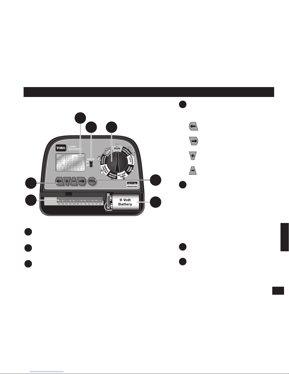
Components Overview
1
LCD Display (
See “LCD Display Overview” for
details
)
2
Sensor Switch
– Use to Enable or Disable the
optional rain sensor.
3
Function Dial
– Select from the controller functions.
(See “Function Dial Overview” for details)
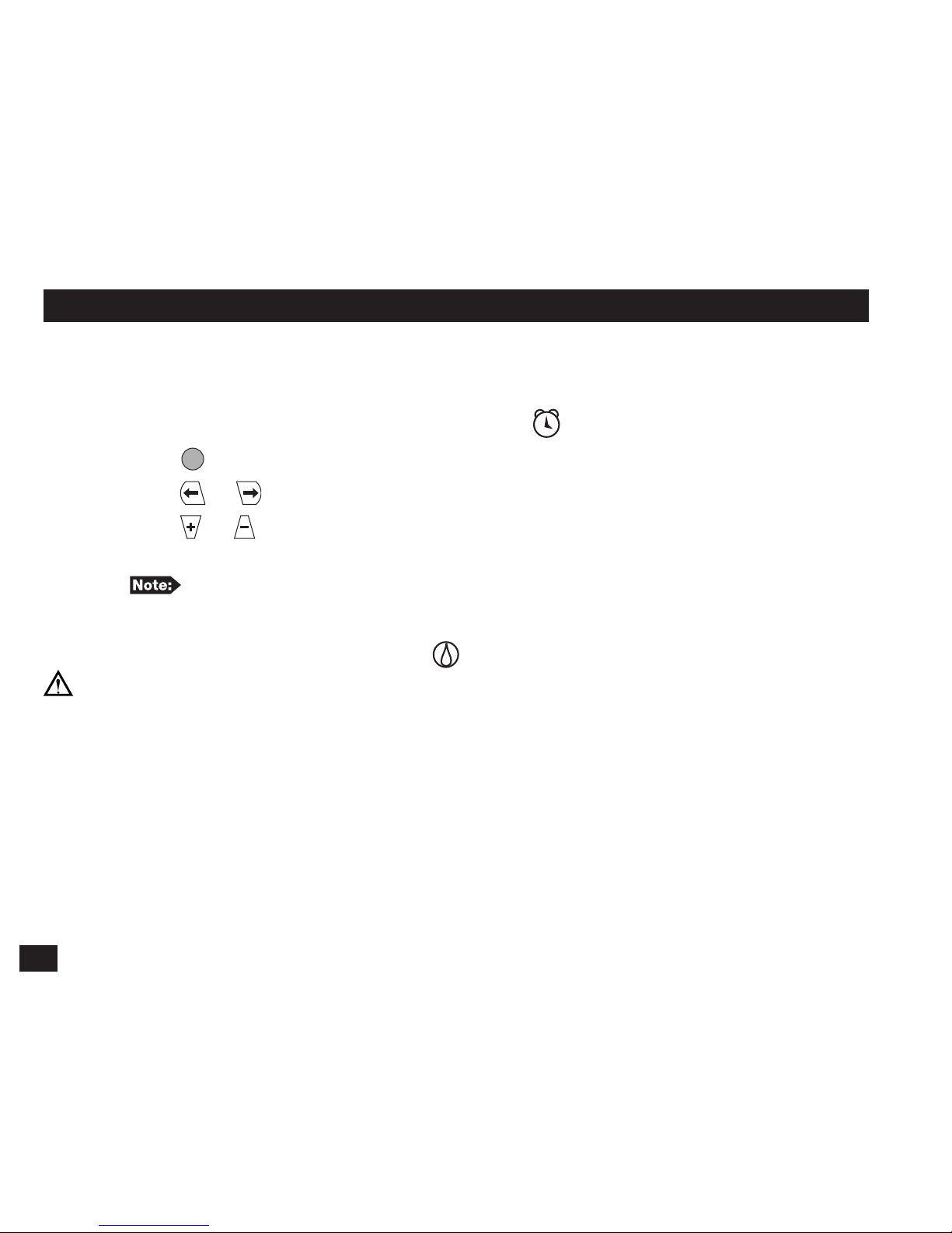
4
Navigational Buttons
– Use to
navigate through the function
menus.
– Navigate to the previous
menu item.
– Navigate to the next
menu item.
– Adjust/Increase the
selected value.
– Adjust/Decrease the
selected value.
5
Terminal Block
RS1
&
RS2
– Sensor
AC1
&
AC2
– AC Power
COM
– Valve Common
MV
– Master Valve
S1
through
S6
– Stations 1–6
(Station count will depend on
4-Zone or 6-Zone model)
6
Program Button
– Press to
select from Program A, B or C.
7
9-Volt Battery (not included)
– Install to retain date, time and
scheduled programs into the
memory.
1
2
3
4
5
6
7
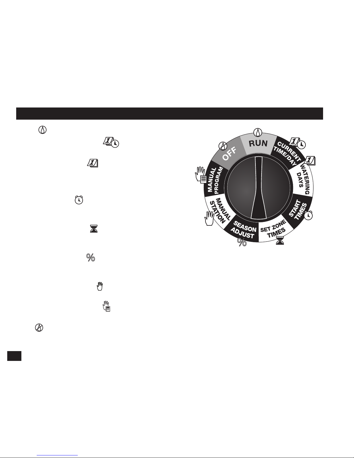
2
Function Dial Overview
RUN
– Select to operate scheduled programs.
CURRENT TIME/DAY
– Select to adjust the
current date and time.
WATERING DAYS
– Select to set the days to
activate the scheduled programs. You can set the
programs to operate on selected weekdays, ODD
days or EVEN days schedule.
START TIMES
– Select to set the time to activate
the scheduled programs. Lawn Master II provides three
start times to each of the three programs.
SET ZONE TIMES
– Select to set the time duration
of the specified station to run. The run times can
be set from one minute and up to six hours.
SEASON ADJUST
– Select to adjust the program’s watering by percentage. You can
decrease your irrigation system’s watering down to 0% (System OFF) or increase watering up
to 200% (double the scheduled watering time).
MANUAL STATION
– Select to activate a single station. You can specify the run time
of the station without affecting any program.
MANUAL PROGRAM
– Select to activate a program regardless of its scheduled
start time.
OFF
– Select to turn off any operation currently in progress. Leave the function dial in the
OFF position to shutdown the sprinkler system.
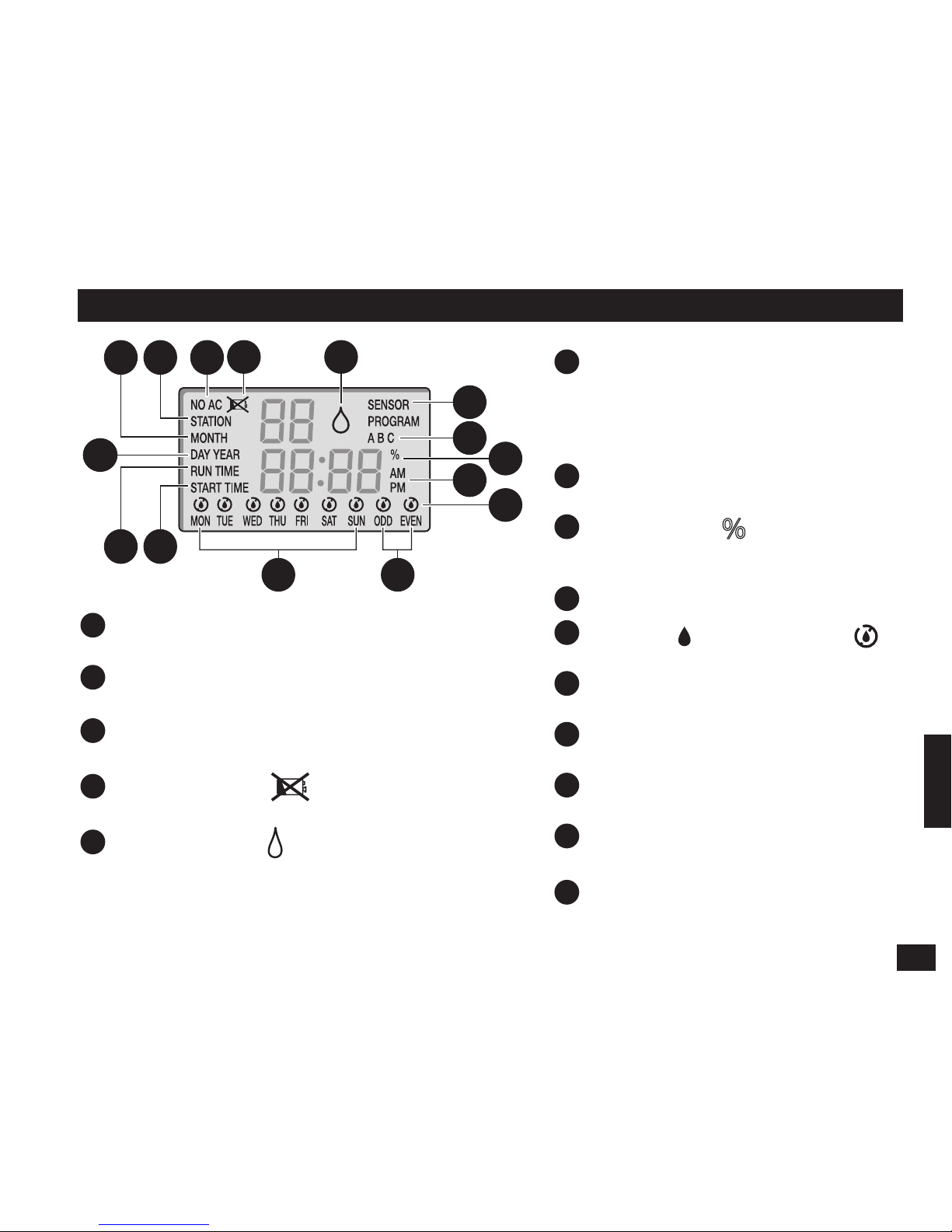
3
LCD Display Overview
1
MONTH
– The flashing 2-digit number
indicates the current month.
2
STATION – Indicates which station number
is selected.
3
NO AC
– Flashes when the AC power source is
not detected.
4
Low/No Battery
– Indicates the need to
install a new 9-Volt battery.
5
Active Watering
– Indicates that a program
or manual operation is currently active.
6
SENSOR
– Indicates that the sensor
terminals have been activated. If a
rain sensor (optional) is installed,
SENSOR indicates that rain has been
detected.
7
PROGRAM A, B or C
– Indicates
which program is selected.
8
Season Adjust
– Indicates that
the automatic programs have been
adjusted.
9
AM
or
PM
indicator.
10
Watering
/ Non-Watering
icon indicators.
11
DAY
– Indicates the current day.
YEAR
– Indicates the current year.
12
RUN TIME
– Indicates the run time
for the displayed station.
13
START TIME
– Indicates the start
time number and duration.
14
Weekdays
– for selective watering
schedule.
15
ODD
or
EVEN
watering schedule.
1 2 3 4 5
6
7
8
9
10
11
12 13
1514
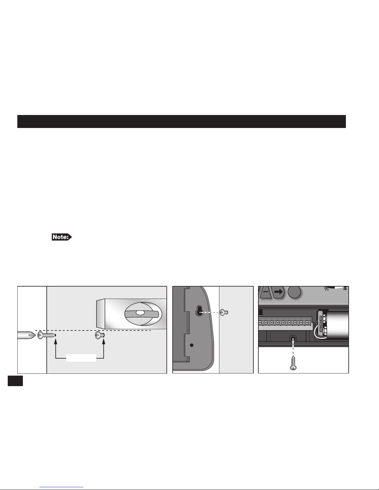
4
Controller Installation
For safe, reliable operation, select an installation site which is:
• Weather protected.
• Within 4 ft. (1.2 m) from a grounded 110 VAC, 60 Hz outlet which is not controlled by
a light switch or utilized by a high current load appliance, such as a refrigerator,
air conditioner or garage door opener.
• Accessible to the sprinkler control valve wiring and optional accessory wiring.
Step 1 – Use the Screw Location Template on the back page to mark the screw locations.
Use a level to align the two screws horizontally. Install two screws, 5 inches
(12.7 cm) apart, into the wall at eye level. Leave the screw extended approximately
1/4 inch (6 mm) from the wall to accommodate the controller case.
If installing into drywall or masonry, install proper screw anchors.
Step 2 – Hang the cabinet using the back panel’s keyhole slot. Make sure the cabinet slides
down securely onto the screws.
Step 3 – (Optional) Remove the controller’s access panel and install a center mounting screw.
Tighten securely.
5’’ (12.7cm)
PRG
SENSOR
ON
OFF
Questions?
(800) 367-8676
www.toro.com
Call the Toro Helpline
(Optional)
5
Battery Installation
The Lawn Master II maintains the programmed schedule and its
time and date by using a 9V battery backup. In the event of a
power outage and the 9V battery is not installed or very low in
power, the controller will reset the date and time to the default
01-01-2007 and 12:00am. Any scheduled watering that is
programmed in the Lawn Master II will also be lost.
Replace the 9V battery yearly to assure that the current
time, date and scheduled programs are retained.
IMPORTANT! Check the controller’s scheduled watering
program after every power outage to prevent interruption to your irrigation
system’s activity.
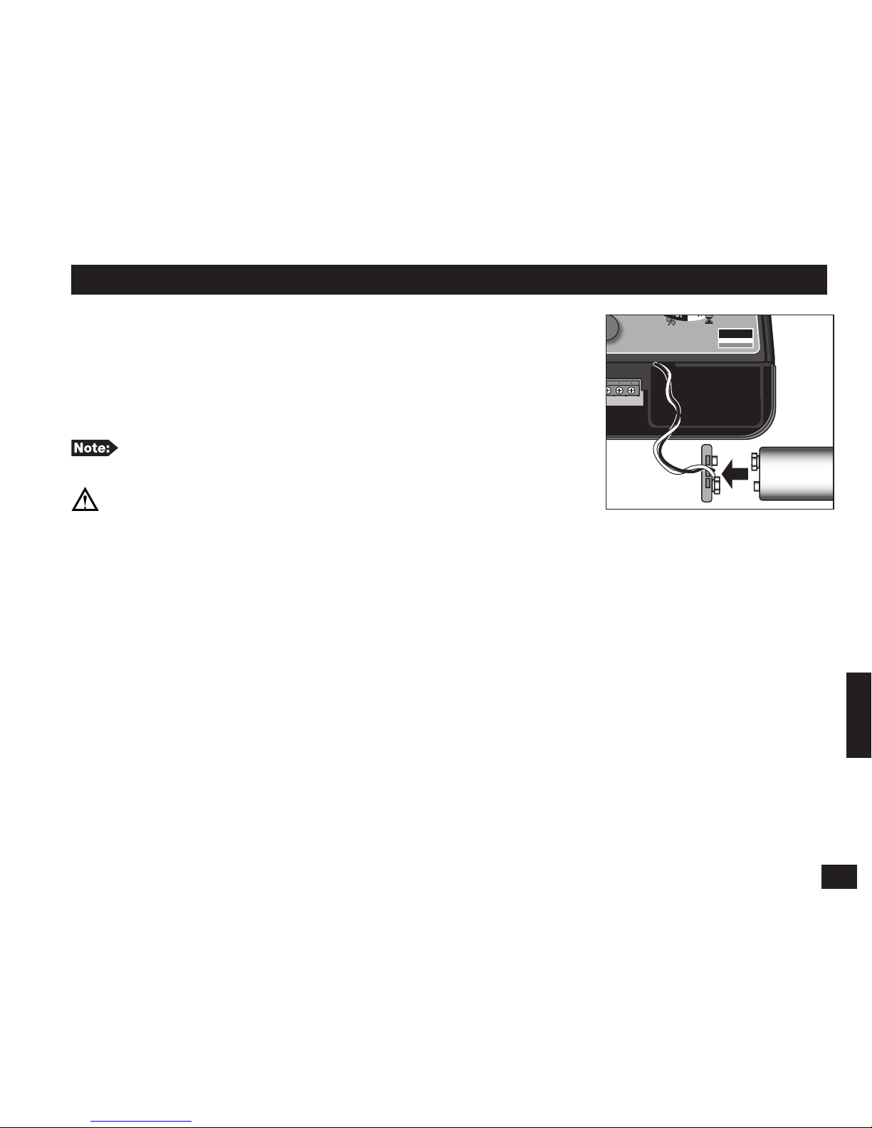
Step 1 – Remove the controller’s lower panel cover to access the battery compartment.
Step 2 – Install the 9V battery to the battery plug.
Step 3 – Secure the battery into the compartment.
Step 4 – Reinstall the lower panel cover.
Questions?
(800) 367-8676
www.toro.com
Call the Toro Helpline
9-Volt
Battery
6
Power Connection
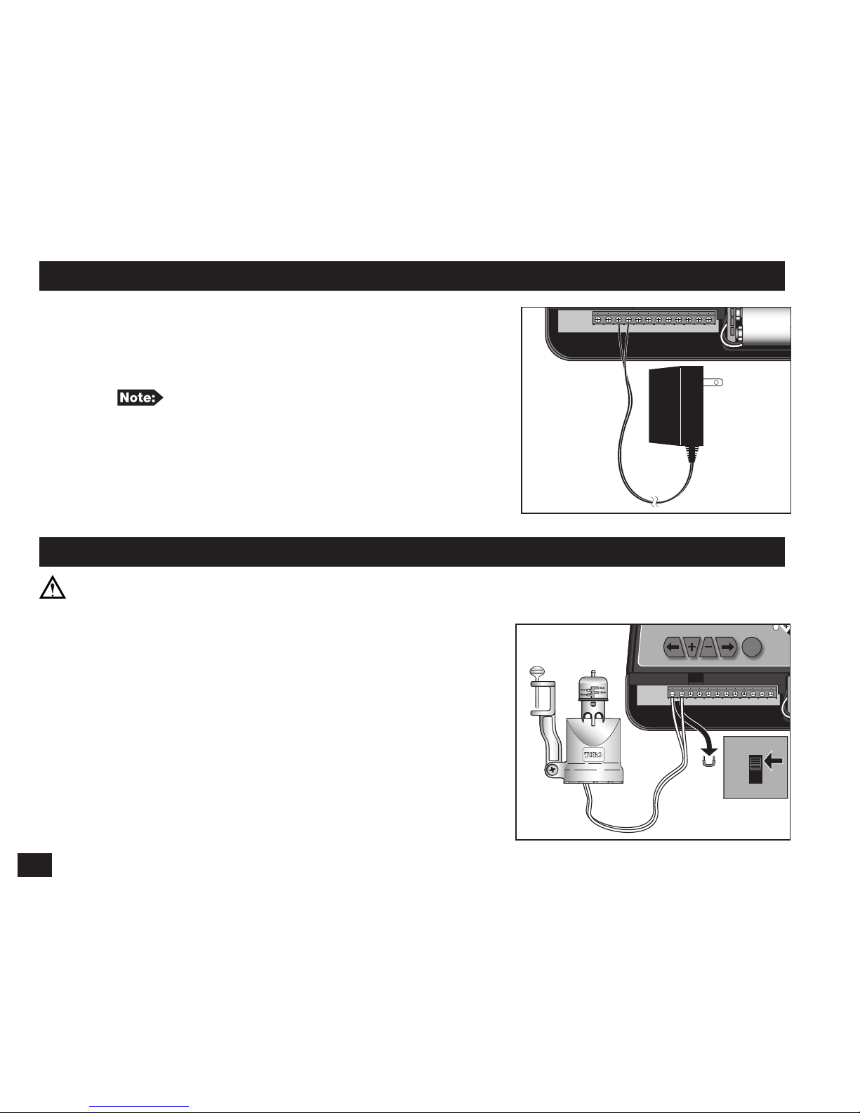
Step 1 – Remove the controller’s lower panel cover
to access the power supply terminals.
Step 2 – Connect the plug-in transformer cables to the
terminals labeled “AC1” and AC2”.
Polarity is not observed in this connection.
Step 3 – Replace the lower panel cover, making sure that
the transformer cable is routed through the
provided opening at the bottom of the controller.
Step 4 – Plug the transformer into a 120 VAC, 60Hz
wall outlet.
Rain Sensor Installation (Optional)
IMPORTANT! The sensor circuit is designed for a NORMALLY-CLOSED rain sensor.
If a rain sensor is not connected, the sensor switch must be in the “OFF” position or the
jumper wire must be installed.
Step 1 – Remove the controller’s lower panel cover
to access the sensor terminals.
Step 2 – Route the rain sensor’s cable to the controller.
Step 3 – Remove the jumper cable from the “RS1” and
“RS2” terminals. Connect the sensor cables to
the terminals.
Step 4 – Replace the lower panel cover.
Step 5 – Place the “SENSOR” switch to “ON” to
monitor the sensor status.
PRG
SENSOR
lawn
master
ON
OFF
Questions?
(800) 367-8676
www.toro.com
Call the Toro Helpline
RS1 RS2 AC1 AC2 COM MV S1 S2 S3 S4 S5 S6
9-Volt
Battery
PRG
SENSOR
lawn
master
ON
OFF
Questions?
(800) 367-8676
www.toro.com
Call the Toro Helpline
SENSOR
ON
OFF
RS1 RS2 AC1 AC2 COM MV S1 S2 S3 S4 S5 S6
9-Volt
Battery
7
Master Valve and Station Connection
Using 18-gauge (maximum 14-gauge wire can be used), multi-strand, direct burial
irrigation valve connection cable is recommended. Select a cable that provides at least one
wire for each valve and one extra wire for the common connection.
IMPORTANT! To prevent corrosion and possible short circuit, use waterproof wire
connectors on all splices.
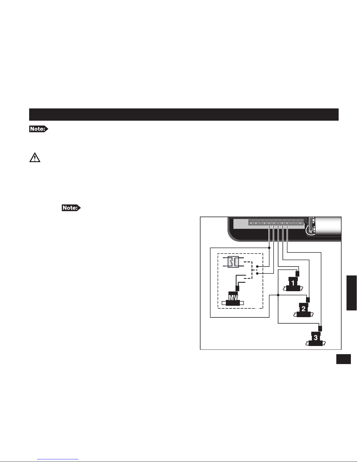
Step 1 – To provide a valve common connection, splice one cable wire (generally the white
wire) and connect it to one solenoid lead from each of the valves.
Step 2 – Connect a separate wire to the remaining solenoid lead from each valve.
For reference, note the wire color code being used for each valve connection
and the associated watering station.
Step 3 – Remove the controller’s lower
panel cover to access the master valve
and station terminals.
Step 4 – Route the wire cable into the controller
through the opening at the base of the
unit.
Step 5 – Secure the designated valve common
wire to the “COM” terminal.
Step 6 – Secure the Master Valve to the “MV”
terminal and the stations to their
corresponding terminals (S1, S2, S3, ...).
Step 7 – Reinstall the lower panel cover.
PRG
SENSOR
lawn
master
ON
OFF
Questions?
(800) 367-8676
www.toro.com
Call the Toro Helpline
RS1 RS2 AC1 AC2 COM MV S1 S2 S3 S4 S5 S6
9-Volt
Battery
S1
S2
S3
COM
COM
MV
8
RUN Position
Rotate the function dial to RUN to enable the controller to operate as programmed
.
Lawn Master II will only operate scheduled programs while in RUN position
.
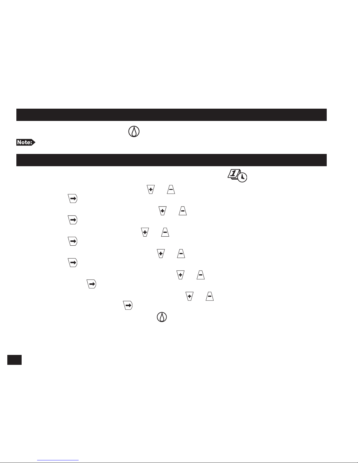
CURRENT TIME/DAY Setup
Step 1 – Place the function dial to the CURRENT TIME/DAY position.
Step 2 – With YEAR displayed, press or to adjust to the current year’s value.
Press to advance to MONTH.
Step 3 – With MONTH displayed, press or to adjust the current month’s value.
Press button to advance to DAY.
Step 4 – With DAY displayed, press or to adjust the current day’s value.
Press to advance to AM/PM.
Step 5 – With AM or PM flashing, press or to select AM or PM.
Press to adjust the HOUR value.
Step 6 – With the HOUR value flashing, press or to adjust the hour to the current
time. Press to adjust the MINUTE value.
Step 7 – With the MINUTE value flashing, press or to adjust the minutes to the
current time. Pressing will return you to the YEAR display (Step 2).
Step 8 – Place the function dial to RUN when finished.

9
WATERING DAYS Setup
The WATERING DAYS setup will dictate when to activate the selected watering program.
Lawn Master II allows you to select Weekdays, ODD days only or EVEN days only watering
schedules. When selecting Weekdays schedule, you can disable specific days.
Step 1 – Place the function dial to the WATERING DAYS position.
Step 2 – Press
PRG
to select the program being modified. Select from A, B or C.
Step 3 – For Weekday scheduling, press until MON–SUN is displayed. All weekdays with
the symbol are designated as an active watering day.
To disable a specific weekday, press or until the desired weekday is flashing.
Press to disable. The icon will be displayed above the non-watering day.
To enable a non-watering day, press or until the desired weekday is flashing.
Press to enable. The icon will be displayed above the active day.
Step 4 – For ODD scheduling, press or until ODD is flashing. Press the button
to activate. The symbol should be displayed above ODD. By selecting ODD
scheduling, Lawn Master II will only water on the ODD numbered days in the
calendar month. ODD scheduling will not water on the 31st but resumes on the 1st.
Step 5 – For EVEN scheduling, press or until EVEN is flashing. Press the button
to activate. The symbol should be displayed above EVEN. By selecting EVEN
scheduling, Lawn Master II will only water on the EVEN numbered days in the
calendar month.
Step 6 – Repeat Steps 2–5 for the remaining programs as necessary.
Step 7 – Return the function dial to RUN when finished.
10
START TIMES Setup
The START TIMES setup will instruct the controller the time to activate the selected program
during an active watering day. Lawn Master II provides three start times per program to
accommodate all your irrigation needs.
Step 1 – Place the function dial to the START TIMES position.
Step 2 – Press
PRG
to select the program being modified. Select from A, B or C.
Step 3 – Press or to select the START TIME number (1, 2 or 3) being modified.
Step 4 – Press or to adjust the time to the desired START TIME. For unused start
times, make sure OFF is displayed. OFF is located between 11:45pm and 12:00am.
Each key-press will increase or decrease the start time by 15 minutes.
Step 5 – Repeat steps 2–4 for the remaining start times and programs as necessary.
Step 6 – Return the function dial to RUN when finished.
IMPORTANT! A program which is set to start while a watering cycle is in progress will
be delayed (stacked) until the current watering cycle is completed. Any stacked programs that
are delayed past midnight will be canceled.
 Loading...