

Page 1
Introduction
The E-Series and RDR OSMAC narrow-band satellite frequency decoder module provides four preprogrammed frequencies,
one of which is selected for use by the placement of a movable jumper located on the module board.
The decoder module utilizes a programmable frequency synthesizer which enables each of the preprogrammed frequencies to be changed as needed for the irrigation site conditions. The software and hardware components provided in this
kit enable the frequency reprogramming task to be easily accomplished.
The Frequency Reprogramming Kit includes the following components:
• External 12 V a.c. power supply (120 V a.c. input for kit #102-1208 and 240 V a.c. input for kit #102-1230)
• Power supply interface adapter and 20-pin ribbon cable (for E-Sereis OSMAC power connection)
• Interface cable assembly (for RDR OSMAC power connection)
• DB-9 serial cable (for decoder module to PC connection)
• Two 3.5" floppy diskettes containing the Frequency Management Program software
Computer System Requirements
The Frequency Management Program, which occupies less than 5 megabytes of disc space, runs on a standard PC with
enough internal memory to run applications under the Windows operating system. The PC must have at least one standard communications port capable of attaching to a device at 1200 baud.
Step 1: Remove the Decoder Module from the Satellite Controller
Caution: Potential damage can occur to the satellite controller if the
decoder module is not disconnected from the controller or RDR unit prior
to performing the frequency reprogramming procedure.
For E-Series OSMAC satellite:
•Place the satellite controller power switch in the Off (O) position.
•Open the cabinet lid and remove the clear plastic cover from the decoder
module assembly.
•Release the ribbon cable connector from the decoder module by moving the
cable receptacle locking tabs outward.
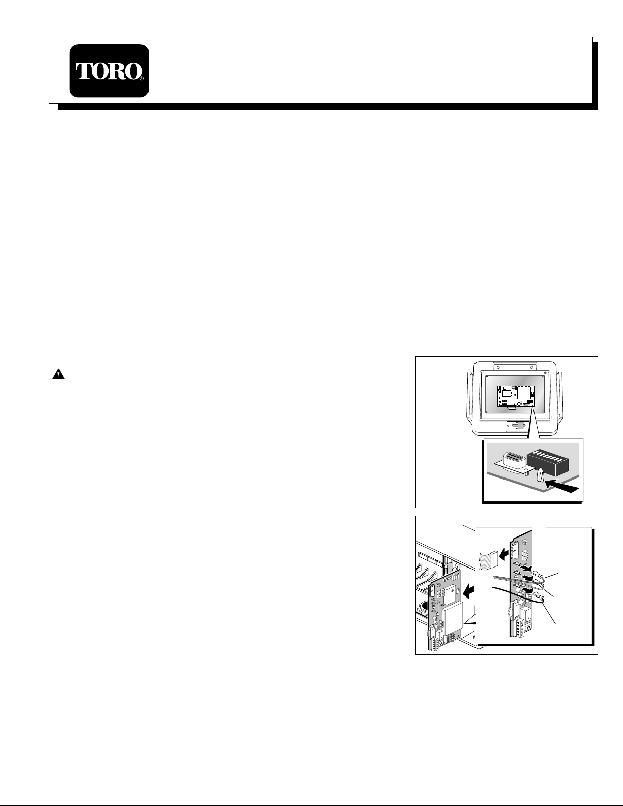
•Carefully remove the decoder module from the controller by compressing the
four standoff locking tabs (indicated in Figure 1) using needle nose pliers or a
flat blade screwdriver. Carefully lift each corner of the module upward just
enough to keep the standoff locking tab compressed. When all four standoffs
are compressed, remove the module assembly from the controller.
For RDR OSMAC satellite:
•Locate the RDR decoder module and unplug the Black common wire to
disconnect power to the module.
•Remove the Orange 12 V a.c. power wire, Red 26 V a.c. power wire and
the flat ribbon cable. Remove any wires connected to the decoder module
terminal block and note their position for proper reinstallation. See Figure 2.
•Carefully slide the decoder module out or the RDR unit.
Step 2: Install the Frequency Management Software
Note: The E-OSMAC decoder Frequency Management Program, written for use on a compatible PC running under the
Windows –95, –98, or NT operating system, allows the user to view the current frequency settings in the E-Sereis or
RDR OSMAC frequency decoder card and to change the settings to appropriate values. Data can be saved on computer
disc files for later retrieval, and values can be edited in order to simplify the chores of modifying frequency selections.
(continued)
Figure 1
Red
26 V a.c.
Orange
12 V a.c.
Black
Common
Figure 2
E-Series and RDR OSMAC Narrow-Band Satellite Controller
Frequency Reprogramming Kit, P/N 102-1208 and 102-1230
User’s Guide
Stand Off Locking Tab
Page 2
Software Installation Procedure (continued)
Important: As is the case during any program installation, it may be necessar y to update some Windows
files.There is always the possibility that some software in a system can be damaged in this process. It is recommended to save any of the PC’s valuable data files on diskette or a network before installing the program.
•Insert Diskette 1 into the floppy drive. Use standard Windows procedures to start the installation. For example: Click
on Start, then Run, then Browse to A:\SETUP.EXE. The install wizard should begin operation and will ask several
questions during the installation process. It is recommended that the program be placed in a folder named
EOSMACFQ. When all questions have been answered, the wizard will complete the installation.
Note: If the frequency reprogramming software was provided via email or some similar method, create a new folder
on your C drive or network for storing the files temporarily, then save them in that folder. The files are named
SETUP.EXE, SETUP.LST, and EOSMACFQ.CAB. Use standard Windows procedures to invoke SETUP.EXE.
•Windows may issue a message regarding updating some system files and restarting the computer. If this occurs, let the
computer reboot. When that operation is complete, start SETUP again. The installation wizard should begin operation.
•In some cases, Windows may issue messages regarding files in use, then give an option to abort the operation or
ignore the conflict. In such cases, choose IGNORE to continue installation.
•Windows may also issue warnings regarding files that are newer on the PC than in the installation suite. Generally, it
is best to keep the newer file.
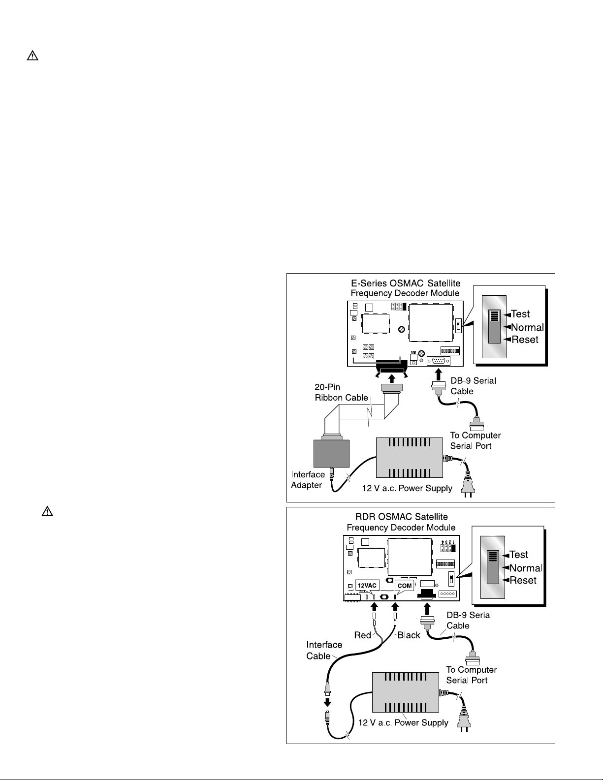
Step 3:Connect the Decoder Module to the Power Supply and Computer
For E-Series OSMAC satellite:
•Plug the power supply output cable into the interface
adapter. Attach the 20-pin ribbon cable to the decoder
module as shown in Figure 3. Make sure the ribbon
cable is properly attached to the socket and the locking tabs are pushed inward.
For RDR OSMAC satellite:
•Connect the power supply to the interface cable as
shown in Figure 3. Connect the Red lead to the
decoder module 12VAC tab and the black lead to the
COM tab.
For both satellite types:
•Connect the DB-9 serial cable to the decoder module
9-pin socket and the serial port of the PC.
•Plug the power supply cord into a wall outlet. The Red
LED on the decoder module should illuminate to indicate that the circuit is On.
•Place the 3-position mode switch in the TEST position.
Important: The switch must be in the TEST
position to enable frequency reprogramming. New
frequencies will not be downloaded if the switch is
in the NORMAL or RESET position.
Figure 4
Figure 3
2
Page 3

Step 4: Program Operation
Start the Frequency Management Program using standard Windows procedures. For example, click on START and
PROGRAMS then select the frequency manager from the list of programs. The program operates through the main form
on the computer screen as shown in Figure 5. (continued)
Figure 5
❷
❶
❸
❹
➎
➏
❶
The top line of the screen contains the program’s title and the standard Windows screen options,
allowing the user to minimize the screen, to make the screen smaller or larger, or to terminate the
program.
❷
The next line on the screen is a menu bar. The items marked FILE, EDIT and COMM PORT can be
used to select files and save data, to edit frequencies, and to select the COMM port to which a
decoder card can be attached. Also on this line is the name of the file currently used to store frequency data.
❸
This is a field containing current frequency data file description. This can be changed as desired,
and it will be saved in the data file along with frequency data in order to provide some assistance
in identifying the source or use of the data.
❹
This is the "Current Frequencies" data column which contains the four values read from the card
attached to the system. Normally, this data is obtained automatically whenever a decoder card is
first attached to the system. Under this column is a button marked "Read Frequencies." Click on
this button at any time to reread the frequencies from the card.
➎
The column marked "Edit Frequencies" contains the four numbers read from the disc file which
can be changed as needed to update the card. Only the entries in this column can be edited,
saved to disc or restored from disc or downloaded to the decoder card. Under this column is a button marked "Download Frequencies." Click on this button at any time to send the frequencies to
the decoder attached to the system.
➏
Below the two command buttons is a field that indicates the decoder status. When a decoder is
attached and communicating with the system, this field will have a green disc and display
"Decoder is Attached.” When no decoder is attached, or is not communicating, the field will show a
red disc and display "No Decoder Attached."
3
Page 4

Program Operation (continued)
•When the program begins operation, it attempts to read frequency and description data from the file that was
accessed during the previous session, and display that information in the EDIT FREQUENCIES column of the main
form. If that file cannot be found, the program will note that fact and display factory default frequencies on the form.
•The program next tries to read and display current frequency data from a decoder card. To be successful, there must
be a decoder card attached, the card must have electrical power and its slide switch must be set to the TEST position. If these conditions are not met, the CURRENT FREQUENCIES fields will be left blank and the form will display
a message that a decoder card is not attached.
Note: Adecoder card may have invalid data in its frequency memory. When the program detects this, it will show the
decoder card as attached, but display a message below the CURRENT FREQUENCIES column stating that the frequency data is bad. Normally, this is not a serious problem since it is only necessary to download valid data to the
decoder card. If this condition persists, the decoder card may be defective.
This condition can also arise if a frequency data upload operation (which can take several seconds) is inadvertently
interrupted. In this case, click on the READ FREQUENCIES button to reread frequency data.
•The program will automatically read frequency data each time a decoder card is replaced. If at any time you wish to
reread the frequencies, click on the READ FREQUENCIES button.
Note: The computer attaches to a decoder card using one of its RS232-type communications ports. The COMM
PORT menu on the form menu bar can be used to select the actual port to be used. Normally, the program saves
the port selection in a configuration file. In case the program cannot find its configuration file on startup, it will use
COMM 1. The selection can be changed any time during program operation.
Step 5: Editing Frequency Values
The four frequency values in the EDIT FREQUENCIES column and the FILE DESCRIPTION field can be changed as
needed, and the four frequency values from the CURRENT FREQUENCIES column can be copied to the EDIT FREQUENCIES column as desired.
•Fields in the EDIT FREQUENCIES column of the form can be edited as desired, whether or not a decoder card is
attached.
•Use the computer’s mouse to move the screen cursor to the FILE DESCRIPTION field, then left-click on the mouse
once. Change the description field as desired. When finished, click on any frequency field or on a menu bar item to
exit that field.
•While a frequency field shows its normal white background color, it cannot be changed. To edit one of the values in
the EDIT FREQUENCIES column, use the computer’s mouse to move the cursor into the field to be changed, then
left-click. The field’s background color should change to gray and editing should be enabled. Use normal editing keys
such as BACKSPACE and DELETE and numeral keys to navigate inside the field and to change numbers. Only
numerals and the decimal point are allowed, and the frequency value must be between 450.1000 and 470.1000.
If the program finds an unacceptable character in a field, or a frequency value that is out of range, it will "beep" using
the computer’s speaker, then restore the field to its previous contents. When editing within a field is complete, click
on another field to edit there or click on the same field to reset the field to its normal background color and close
editing on that field.
Note: The program stores the original contents of any EDIT FREQUENCY field that is changed, maintaining a "stack"
of five prior values, in reverse order; that is, the last changed value is on the top of the stack. If an error in some
changed value is detected, click on the EDIT menu button to pull that menu down. Click on the UNDO button to
restore the last field changed. The UNDO button will be active only when there are items on the stack.
•The contents of any CURRENT FREQUENCY or EDIT FREQUENCY field can be copied to any one of the EDIT
FREQUENCIES fields. Click on the field to be copied to activate it, then pull the EDIT menu down and select COPY.
Click on the EDIT FREQUENCY field you wish to copy to, then select PASTE from the EDIT menu to complete the
copy operation.
•When editing is complete, click on the DOWNLOAD FREQUENCIES button to send data to the attached decoder
card. If there is no decoder card attached, clicking on this button will have no effect.
Note: The program does not save the frequency data automatically. To save frequency values to disk, refer to
“Step 6: File Operations” on page 5 for detailed information.
•When a session is complete, click on the “X” in the upper right corner of the form, or select Exit from the File menu
on the menu bar. The program will save the name of the frequency file being used for use in the next session, then
terminate.
4
Page 5

Step 6: File Operations
Saving a File:
Contents of the FILE DESCRIPTION and the EDIT FREQUENCIES fields data can be saved in files on the computer’s hard disc or floppy drive, then recalled at a later time when needed.
•Save the contents of the edit fields in the selected file by pulling down the FILE menu and selecting SAVE.
•To create a new file for saving frequency data, pull down the FILE menu from the menu bar and select SAVE AS.
Use the Windows dialog to create a new folder or file on the hard disc or diskette. The program will save values in
the file, and keep the file name as the current selection. While this mechanism is intended primarily for building new
frequency files, it can be used to overwrite the data in an existing file. If the file selected from the Windows dialog
exists, the program will display a warning message to that effect. Select YES from the warning message box to use
the existing file, or select NO or CANCEL to void the SAVE AS operation.
Opening a File:
•As described previously, the program will attempt to read the same disc file that had been used at the end of the previous session. If that file is not available, the program will display default frequency values and mark the fact that no
file has been selected.
•To open a different existing frequency file, pull down the FILE menu from the menu bar and select OPEN. The program will start a Windows dialog. Browse through the computer system to find and select a file. The new selection
will be opened and its contents will appear in the edit fields. The file name will appear near the top of the main form.
Step 7:Test communication and satellite controller operation
•Place the decoder module mode switch in the NORMAL (center) position.
•Select the desired channel frequency (1–4) by placing the jumper
plug on the appropriate jumper pin set as shown in Figure 6.
(Channel frequency number 1 is selected in this example.)
•If the satellite controller address code was not previously set during
initial installation, set the address code at this time .
•The address numbers range from 1 (001) through 255 and are issued
to the satellite through an array of eight DIP switches, as shown in
Figure 7. In the down position, the switch is Off (open) and represents
a value of 0 (zero). In the up position, the switch is On (closed) and
represents the following value:
Sw 1 = 1 Sw 2 = 2 Sw 3 = 4 Sw 4 = 8
Sw 5 = 16 Sw 6 = 32 Sw 7 = 64 Sw 8 = 128
Example: To set satellite address number 50 (050), start with all eight
DIP switches in the Off position. Using a pen or small screwdriver,
move switch numbers 2, 5 and 6 to the On position (2+16+32=50).
See Figure 7.
•Referring to the switch position matrix in Figure 8 on the back page,
locate the desired address number and set the DIP switches accordingly. A dot in the switch position represents On; an open box represents Off.
•For E-Series OSMAC only: Confirm that the satellite controller power
switch is Off (O) and the Pump and Field Common control switches
are in Off (center) position.
•Reinstall the decoder module, making the appropriate wire or cable
connections.
For RDR OSMAC satellite only:
Important: Attach the Red 12 V a.c. and Orang e 26 V a.c. wires prior to connecting the Black Common wire
to the decoder module. Ensure all wires are properly routed to prevent interference with the RDR cabinet door.
•E-Series OSMAC only: Place the satellite controller power switch in the On (I) position.
•Send a series of commands to the satellite controller using the OSMAC base station programmed to the correct fre-
quency and controller address. Verify that the decoder module is receiving the commands and the controller is
responding properly.
•E-Series OSMAC only: Move the Pump and Common Switches to the AUTO (down) position. Reinstall the clear
plastic cover over the decoder module and close the controller cabinet.
Figure 6
Figure 7
1 2 3 4 5 6 7 8
RDR OSMAC
E-OSMAC
RDR OSMAC
E-OSMAC
5
Page 6

1 2 3 4 5 6 7 8 1 2 3 4 5 6 7 8 1 2 3 4 5 6 7 8
1 2 3 4 5 6 7 8 1 2 3 4 5 6 7 8
Satellite address DIP switch matrix – = On = Off
•
Figure 8
© 2001 The Toro Company, Irrigation Division, An ISO 9001-Certified Facility From Number 373-0129 Rev. B
001
002
003
004
005
006
007
008
009
010
011
012
013
014
015
016
017
018
019
020
021
022
023
024
025
026
027
028
029
030
031
032
033
034
035
036
037
038
039
040
041
042
043
044
045
046
047
048
049
050
051
052
053
054
055
056
057
058
059
060
061
062
063
064
065
066
067
068
069
070
071
072
073
074
075
076
077
078
079
080
081
082
083
084
085
086
087
088
089
090
091
092
093
094
095
096
097
098
099
100
101
102
103
104
105
106
107
108
109
110
111
112
113
114
115
116
117
118
119
120
121
122
123
124
125
126
127
128
129
130
131
132
133
134
135
136
137
138
139
140
141
142
143
144
145
146
147
148
149
150
151
152
153
154
155
156
157
158
159
160
161
162
163
164
165
166
167
168
169
170
171
172
173
174
175
176
177
178
179
180
181
182
183
184
185
186
187
188
189
190
191
192
193
194
195
196
197
198
199
200
201
202
203
204
205
206
207
208
209
210
211
212
213
214
215
216
217
218
219
220
221
222
223
224
225
226
227
228
229
230
231
232
233
234
235
236
237
238
239
240
241
242
243
244
245
246
247
248
249
250
251
252
253
254
255
 Loading...