

Page 1
Form No. 3357-573 Rev A
G004222
TX 525 Compact Utility Loader
Model No. 22333 —Serial No. 270000001 and Up
Model No. 22334 —Serial No. 270000001 and Up
Register your product at www.Toro.com Original Instructions (EN)
Page 2

Warning
CALIFORNIA
Pr oposition 65 W ar ning
Diesel engine exhaust and some of its
constituents ar e kno wn to the State of
Calif or nia to cause cancer , bir th defects, and
other r epr oducti v e har m.
Because in some areas there are local, state , or
federal regulations requiring that a spark ar rester
be used on the engine of this mac hine , a spark
ar rester is a v ailable as an option. If y ou require a
spark ar restor , contact y our A uthorized Ser vice
Dealer .
Gen uine T oro spark ar resters are appro v ed b y the
USD A F orestr y Ser vice .
Important: It is a violation of Calif or nia
Public R esource Code Section 4442 to use
or operate the engine on an y f or est-co v er ed,
br ush-co v er ed, or g rass-co v er ed land without
a spar k ar r ester muf fler maintained in w or king
order , or the engine constricted, equipped, and
maintained f or the pr ev ention of fir e. Other
states or federal ar eas may ha v e similar la ws.
into a plate mounted under the hood near the belt
dri v e . W rite the n umbers in the space pro vided.
Model No.
Serial No.
T his man ual identifies potential hazards and has
safety messag es identified b y the safety aler t
symbol ( Figure 1 ), whic h signals a hazard that ma y
cause serious injur y or death if y ou do not follo w
the recommended precautions .
Figure 1
1. Safety alert symbol
T his man ual uses 2 other w ords to highlight
infor mation. Impor tant calls attention to special
mec hanical infor mation and Note emphasizes
g eneral infor mation w or th y of special attention.
T he enclosed Engine Owner’ s Man ual is
supplied f or inf or mation r egarding the US
En vir onmental Pr otection Agency (EP A) and
the Calif or nia Emission Contr ol R egulation of
emission systems, maintenance, and w ar ranty .
R eplacements may be order ed thr ough the
engine man uf actur er .
Introduction
R ead this infor mation carefully to lear n ho w to
operate and maintain y our product properly and
to a v oid injur y and product damag e . Y ou are
responsible for operating the product properly
and safely .
Y ou ma y contact T oro directly at www .T oro .com
for product and accessor y infor mation, help
finding a dealer , or to register y our product.
W henev er y ou need ser vice , g en uine T oro par ts ,
or additional infor mation, contact an A uthorized
Ser vice Dealer or T oro Customer Ser vice and ha v e
the model and serial n umbers of y our product
ready . T he model and serial n umbers are stamped
© 2006—The Toro® Company
8111 Lyndale Avenue South
Bloomington, MN 55420
Contact us at www.Toro.com.
2
Printed in the USA.
All Rights Reserved
Page 3

Contents
Introduction . . . . . . . . . . . . . . . . . . . . . . . . . . . . . . . . . . . . . . . . . . . . . . . . . . . . . . . 2
Safety . . . . . . . . . . . . . . . . . . . . . . . . . . . . . . . . . . . . . . . . . . . . . . . . . . . . . . . . . . . . . . . . . . 4
Safe Operating Practices . . . . . . . . . . . . . . . . . . . . . . 4
Sound Pressure . . . . . . . . . . . . . . . . . . . . . . . . . . . . . . . . . . . . 7
Sound P o w er . . . . . . . . . . . . . . . . . . . . . . . . . . . . . . . . . . . . . . . 7
Vibration . . . . . . . . . . . . . . . . . . . . . . . . . . . . . . . . . . . . . . . . . . . . . 7
Slope Char t . . . . . . . . . . . . . . . . . . . . . . . . . . . . . . . . . . . . . . . . . 8
Safety and Instr uctional Decals . . . . . . . . . . . . 9
Setup . . . . . . . . . . . . . . . . . . . . . . . . . . . . . . . . . . . . . . . . . . . . . . . . . . . . . . . . . . . . . . . . 12
1 Acti v ating the Batter y . . . . . . . . . . . . . . . . . . . . . . 12
2 Charging the Batter y . . . . . . . . . . . . . . . . . . . . . . . 13
3 Chec king Fluid Lev els . . . . . . . . . . . . . . . . . . . . . 14
Product Ov er view . . . . . . . . . . . . . . . . . . . . . . . . . . . . . . . . . . . . . . . . . . . . . 15
Controls . . . . . . . . . . . . . . . . . . . . . . . . . . . . . . . . . . . . . . . . . . . 16
Specifications . . . . . . . . . . . . . . . . . . . . . . . . . . . . . . . . . . . 19
Operation . . . . . . . . . . . . . . . . . . . . . . . . . . . . . . . . . . . . . . . . . . . . . . . . . . . . . . . . . . 21
Filling the Fuel T ank . . . . . . . . . . . . . . . . . . . . . . . . . . 21
Chec king the Engine Oil Lev el . . . . . . . . . . . 21
Chec king the Hy draulic Fluid
Lev el . . . . . . . . . . . . . . . . . . . . . . . . . . . . . . . . . 22
Chec king, Adding, and Bleeding
the Engine Coolant . . . . . . . . . . . . 23
Bleeding the Fuel System . . . . . . . . . . . . . . . . . . . 24
Star ting and Stopping the
Engine . . . . . . . . . . . . . . . . . . . . . . . . . . . . . . 25
Stopping the T raction Unit . . . . . . . . . . . . . . . . . 25
Mo ving a Non-functioning
T raction Unit . . . . . . . . . . . . . . . . . . . . . 26
Using the Cylinder Loc k . . . . . . . . . . . . . . . . . . . . . 26
Using Attac hments . . . . . . . . . . . . . . . . . . . . . . . . . . . . 27
Securing the T raction Unit for
T ranspor t . . . . . . . . . . . . . . . . . . . . . . . . . . 28
Lifting the T raction Unit . . . . . . . . . . . . . . . . . . . . 28
Maintenance . . . . . . . . . . . . . . . . . . . . . . . . . . . . . . . . . . . . . . . . . . . . . . . . . . . . . . 29
R ecommended Maintenance
Sc hedule(s) . . . . . . . . . . . . . . . . . . . . . . . . . . . . . . . 29
Premaintenance Procedures . . . . . . . . . . . . . . . . . . . . . . . 30
Opening the Hood . . . . . . . . . . . . . . . . . . . . . . . . . . . . 30
Closing the Hood . . . . . . . . . . . . . . . . . . . . . . . . . . . . . . 30
Opening the R ear Access
Co v er . . . . . . . . . . . . . . . . . . . . . . . . . . . . . . . . 30
Closing the R ear Access Co v er . . . . . . . . . . . 31
R emo ving the Side Screens . . . . . . . . . . . . . . . . . 31
Installing the Side Screens . . . . . . . . . . . . . . . . . . 31
Lubrication . . . . . . . . . . . . . . . . . . . . . . . . . . . . . . . . . . . . . . . . . . . . . . . . 31
Greasing the T raction Unit . . . . . . . . . . . . . . . . . 31
Engine Maintenance . . . . . . . . . . . . . . . . . . . . . . . . . . . . . . . . . . 32
Ser vicing the Air Cleaner . . . . . . . . . . . . . . . . . . . 32
Ser vicing the Engine Oil . . . . . . . . . . . . . . . . . . . . 33
Fuel System Maintenance . . . . . . . . . . . . . . . . . . . . . . . . . . 34
Chec king the Fuel Lines and
Connections . . . . . . . . . . . . . . . . . . . . . . 34
Draining the Fuel Filter/W ater
Se parator . . . . . . . . . . . . . . . . . . . . . . . . . . . 34
R e placing the Fuel Filter
Canister . . . . . . . . . . . . . . . . . . . . . . . . . . . . . 35
Draining the Fuel T ank . . . . . . . . . . . . . . . . . . . . . . 35
Electrical System Maintenance . . . . . . . . . . . . . . . . . . . 35
Ser vicing the Batter y . . . . . . . . . . . . . . . . . . . . . . . . . . 35
Dri v e System Maintenance . . . . . . . . . . . . . . . . . . . . . . . . . 37
Ser vicing the T rac ks . . . . . . . . . . . . . . . . . . . . . . . . . . . 37
Cooling System Maintenance . . . . . . . . . . . . . . . . . . . . . 41
Ser vicing the Cooling System . . . . . . . . . . . . . 41
Belt Maintenance . . . . . . . . . . . . . . . . . . . . . . . . . . . . . . . . . . . . . . . 42
Chec king the Condition of
the Hy draulic Pump
Belt . . . . . . . . . . . . . . . . . . . . . . . . . . . . . . . . . . . 42
Chec king the Alter nator/F an Belt
T ension . . . . . . . . . . . . . . . . . . . . . . . . . . . . . 42
Controls System Maintenance . . . . . . . . . . . . . . . . . . . . 42
Adjusting the T raction Control
Alignment . . . . . . . . . . . . . . . . . . . . . . . . . 42
Adjusting the T raction Control
Neutral P osition . . . . . . . . . . . . . . . . 43
Adjusting the T rac king of the
T raction Control, Full
F orw ard P osition . . . . . . . . . . . . . . . 43
Hy draulic System Maintenance . . . . . . . . . . . . . . . . . . 44
R e placing the Hy draulic Filter . . . . . . . . . . . . 44
Changing the Hy draulic Fluid . . . . . . . . . . . . . 45
Chec king the Hy draulic Lines . . . . . . . . . . . . . 45
Cleaning . . . . . . . . . . . . . . . . . . . . . . . . . . . . . . . . . . . . . . . . . . . . . . . . . . . . 46
R emo ving Debris from the
T raction Unit . . . . . . . . . . . . . . . . . . . . . 46
Cleaning the Chassis . . . . . . . . . . . . . . . . . . . . . . . . . . 46
Storag e . . . . . . . . . . . . . . . . . . . . . . . . . . . . . . . . . . . . . . . . . . . . . . . . . . . . . . . . . . . . . . 47
T roubleshooting . . . . . . . . . . . . . . . . . . . . . . . . . . . . . . . . . . . . . . . . . . . . . . . . 48
Sc hematics . . . . . . . . . . . . . . . . . . . . . . . . . . . . . . . . . . . . . . . . . . . . . . . . . . . . . . . . 54
3
Page 4
Safety
hearing protection. Long hair , loose clothing
or jew elr y ma y g et tangled in mo ving par ts .
Impr oper use or maintenance by the operator
or o wner can r esult in injur y . T o r educe
the potential f or injur y , compl y with these
safety instr uctions and al w ays pay attention
to the safety aler t symbol , which means:
Caution , W ar ning , or Danger —per sonal
safety instr uction. F ailur e to compl y with the
instr uction may r esult in per sonal injur y or
death.
Safe Operating Practices
T his product is capable of amputating hands and
feet. Alw a ys follo w all safety instr uctions to a v oid
serious injur y or death.
Engine exhaust contains carbon mono xide,
an odor less, deadl y poison that can kill y ou.
Do not r un the engine indoor s or in an
enclosed ar ea.
Training
• R ead the Operator’ s Manual and other training
material. If the operator(s) or mec hanic(s) can
not read English, it is the o wner’ s responsibility
to explain this material to them.
• Become familiar with the safe operation of the
equipment, operator controls , and safety signs .
• All operators and mec hanics should be trained.
T he o wner is responsible for training the users .
• Nev er let c hildren or untrained people operate
or ser vice the equipment. Local regulations
ma y restrict the ag e of the operator .
• T he o wner/user can prev ent and is responsible
for accidents or injuries occur ring to himself
or herself , other people or proper ty .
Preparation
• Ev aluate the ter rain to deter mine what
accessories and attac hments are needed to
properly and safely perfor m the job . Only use
accessories and attac hments appro v ed b y the
man ufacturer .
• Inspect the area where the equipment is to be
used and remo v e all objects suc h as roc ks , to ys ,
and wire whic h can be thro wn b y the mac hine .
• Use extra care when handling fuels . T hey are
flammable and v apors are explosi v e .
– Use only an appro v ed container
– Nev er remo v e the fuel cap or add fuel with
the engine r unning . Allo w the engine to
cool before refueling . Do not smok e .
– Nev er refuel or drain the mac hine indoors .
• Chec k that the operator’ s presence controls ,
safety switc hes , and shields are attac hed and
functioning properly . Do not operate unless
they are functioning properly .
Operation
• Nev er r un an engine in an enclosed area.
• Only operate in g ood light, k ee ping a w a y from
holes and hidden hazards .
• Be sure all dri v es are in neutral and parking
brak e is eng ag ed before star ting the engine .
Only star t the engine from the operator’ s
position.
• Slo w do wn and use extra care on hillsides . Be
sure to tra v el in the recommended direction
on hillsides . T urf conditions can affect the
mac hine’ s stability .
• Slo w do wn and use caution when making tur ns
and when c hanging directions on slopes .
• Nev er operate with the guards not securely
in place . Be sure all interloc ks are attac hed,
adjusted properly , and functioning proper ty .
• Do not c hang e the engine g o v er nor setting or
o v erspeed the engine .
• Stop on lev el g round, lo w er implements ,
diseng ag e the auxiliar y h y draulics , eng ag e
parking brak e , shut off the engine before
lea ving the operator’ s position for any reason.
• K ee p hands and feet a w a y from mo ving
attac hments .
• Look behind and do wn before bac king up to
be sure of a clear path.
• W ear appropriate clothing including hard hat,
safety glasses , long pants , safety shoes , and
• Nev er car r y passeng ers and k ee p pets and
b ystanders a w a y .
4
Page 5

• Slo w do wn and use caution when making tur ns
and crossing roads and sidew alks .
• Do not operate the mac hine under the
influence of alcohol or dr ugs .
• Use care when loading or unloading the
mac hine into a trailer or tr uc k.
• Use care when approac hing blind cor ners ,
shr ubs , trees , or other objects that ma y obscure
vision.
• R ead all attac hment man uals .
• Ensure that the area is clear of other people
before operating the traction unit. Stop the
traction unit if any one enters the area.
• Nev er lea v e a r unning traction unit unattended.
Alw a ys lo w er the loader ar ms , stop the engine ,
set the parking brak e , and remo v e the k ey
before lea ving .
• Do not ex ceed the rated operating capacity , as
the traction unit ma y become unstable whic h
ma y result in loss of control.
• Do not car r y a load with the ar ms raised.
Alw a ys car r y loads close to the g round.
• Do not o v er -load the attac hment and alw a ys
k ee p the load lev el when raising the loader
ar ms . Logs , boards , and other items could roll
do wn the loader ar ms , injuring y ou.
• Nev er jerk the controls; use a steady motion.
• W atc h for traffic when operating near or
crossing roadw a ys .
• Do not touc h par ts whic h ma y be hot
from operation. Allo w them to cool before
attempting to maintain, adjust, or ser vice .
• Chec k for o v erhead clearances (i.e . branc hes ,
doorw a ys , electrical wires) before dri ving under
any objects and do not contact them.
• Ensure that y ou operate the traction unit in
areas where there are no obstacles in close
pro ximity to the operator . F ailure to maintain
adequate distance from trees , w alls , and other
bar riers ma y result in injur y as the traction unit
bac ks up during operation if the operator is not
attenti v e to the sur roundings . Only operate
the unit in areas where there is sufficient
clearance for the operator to safely maneuv er
the product.
• Before dig ging, ha v e the area mark ed for
underg round utilities , and do not dig in mark ed
areas .
• Locate the pinc h point areas mark ed on the
traction unit and attac hments and k ee p hands
and feet a w a y from these areas .
• Before operating the traction unit with an
attac hment, ensure that the attac hment is
properly installed.
Slope Operation
Slopes are a major factor related to loss-of-control
and tip-o v er accidents , whic h can result in sev ere
injur y or death. All slopes require extra caution.
• Do not operate the traction unit on hillsides
or slopes ex ceeding the angles recommended
in the Stability Data section in Specifications ,
pag e 19 , and those in the attac hment Operator’ s
Manual . See also the Slope Char t , pag e 8 .
• Operate up and do wn slopes with the
hea vy end of the traction unit uphill. W eight
distribution c hang es . An empty buc k et will
mak e the rear of the traction unit the hea vy
end, and a full buc k et will mak e the front of
the traction unit the hea vy end. Most other
attac hments will mak e the front of traction
unit the hea vy end.
• Raising the loader ar ms on a slope will affect
the stability of the mac hine . W henev er
possible , k ee p the loader ar ms in the lo w ered
position when on slopes .
• R emo ving an attac hment on a slope will mak e
the rear of the traction unit hea vy . R efer to
the Stability Data section in Specifications ,
pag e 19 , to deter mine whether the attac hment
can be safely remo v ed on the slope .
• R emo v e obstacles suc h as roc ks , tree limbs , etc .
from the w ork area. W atc h for holes , r uts , or
bumps , as unev en ter rain could o v er tur n the
traction unit. T all g rass can hide obstacles .
• Use only T oro-appro v ed attac hments .
Attac hments can c hang e the stability and
the operating c haracteristics of the traction
unit. W ar ranty ma y be v oided if used with
unappro v ed attac hments .
• K ee p all mo v ements on slopes slo w and
g radual. Do not mak e sudden c hang es in speed
or direction.
• A v oid star ting or stopping on a slope . If the
traction unit loses traction, proceed slo wly ,
straight do wn the slope .
5
Page 6

• A v oid tur ning on slopes . If y ou m ust tur n, tur n
slo wly and k ee p the hea vy end of the traction
unit uphill.
• Do not operate near drop-offs , ditc hes ,
or embankments . T he traction unit could
suddenly tur n o v er if a trac k g oes o v er the edg e
of a cliff or ditc h, or if an edg e ca v es in.
• Do not operate on w et g rass . R educed traction
could cause sliding .
• Do not park the traction unit on a hillside
or slope without lo w ering the attac hment to
the g round, setting the parking brak e , and
c hoc king the trac ks .
Maintenance and Storage
• Diseng ag e the auxiliar y h y draulics , lo w er
the attac hment, set the parking brak e , stop
the engine , and remo v e the k ey . W ait for all
mo v ement to stop before adjusting, cleaning,
or re pairing .
• Clean debris from attac hments , dri v es ,
m ufflers , and engine to help prev ent fires .
Clean up oil or fuel spillag e .
• If any maintenance or re pair requires the loader
ar ms to be in the raised position, secure the
ar ms in the raised position with the h y draulic
cylinder loc k.
• Secure the loader ar m v alv e with the loader
v alv e loc k anytime y ou need to stop the
mac hine with the loader ar ms raised.
• K ee p n uts and bolts tight. K ee p equipment in
g ood condition.
• Nev er tamper with safety devices .
• K ee p the traction unit free of g rass , lea v es ,
or other debris build-up . Clean up oil or fuel
spillag e . Allo w the traction unit to cool before
storing .
• Use extra care when handling fuels . T hey are
flammable and v apors are explosi v e .
– Use only an appro v ed container .
– Nev er remo v e the fuel cap or add fuel when
the engine is r unning . Allo w the engine to
cool before refueling . Do not smok e .
– Nev er refuel the traction unit indoors .
• Let the engine cool before storing and do not
store near flame .
• Do not store fuel near flames or drain indoors .
• P ark the mac hine on lev el g round. Nev er allo w
untrained personnel to ser vice the mac hine .
• Use jac k stands to suppor t components when
required.
• Carefully release pressure from components
with stored energ y .
• Disconnect the batter y before making any
re pairs . Disconnect the neg ati v e ter minal first
and the positi v e last. R econnect positi v e first
and neg ati v e last.
• K ee p hands and feet a w a y from mo ving par ts .
If possible , do not mak e adjustments with the
engine r unning .
• Charg e batteries in an open w ell v entilated
area, a w a y from spark and flames . Unplug the
c harg er before connecting or disconnecting it
from the batter y . W ear protecti v e clothing and
use insulated tools .
– Nev er store the traction unit or fuel
container inside where there is an open
flame , suc h as near a w ater heater or
fur nace .
– Nev er fill a container while it is inside a
v ehicle , tr unk, pic k-up bed, or any surface
other than the g round.
– K ee p container nozzle in contact with the
tank during filling .
• Stop and inspect the equipment if y ou strik e
an object. Mak e any necessar y re pairs before
restar ting .
• Use only g en uine T oro re placement par ts to
ensure that original standards are maintained.
• K ee p all par ts in g ood w orking condition and
all hardw are tightened. R e place all w or n or
damag ed decals .
6
Page 7

• Batter y acid is poisonous and can cause bur ns .
A v oid contact with skin, eyes , and clothing .
Protect y our face , eyes , and clothing when
w orking with a batter y .
• Batter y g ases can explode . K ee p cig arettes ,
sparks and flames a w a y from the batter y .
• K ee p y our body and hands a w a y from pin
hole leaks or nozzles that eject high pressure
h y draulic fluid. Use cardboard or paper to
find h y draulic leaks; nev er use y our hands .
Hy draulic fluid escaping under pressure can
penetrate skin and cause injur y requiring
surg er y within a few hours b y a qualified
surg eon or g ang rene ma y result.
Sound Pressure
T his unit has a maxim um sound pressure lev el
at the operator’ s ear of 88 dB A, based on
measurements of identical mac hines per EN
11201.
Sound Power
T his unit has a guaranteed sound po w er lev el of
103 dB A, based on measurements of identical
mac hines per EN 6395.
Vibration
T his unit does not ex ceed a hand/ar m vibration
lev el of 1.5 m/s
identical mac hines per EN 1033.
2
, based on measurements of
7
Page 8

Slope Chart
8
Page 9
Safety and Instructional Decals
Safety decals and instr uctions are easily visible to the operator and are located near any
area of potential dang er . R e place any decal that is damag ed or lost.
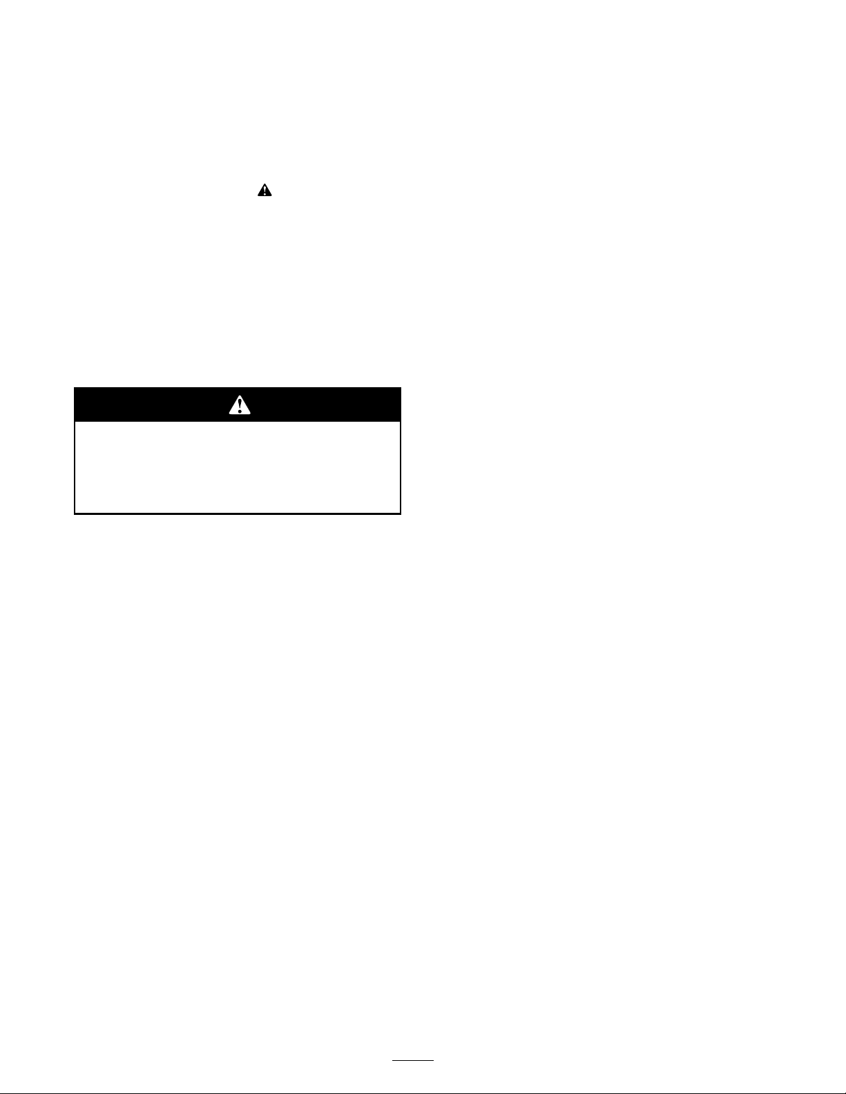
1. Operator’s Manual location
2. Engine—stop
3. Engine—run
4. Engine—start
5. Hour meter
6. Fuel gauge—diesel 10. Glow plug 14. Warning—read the
7. Engine oil 11. Slow 15. Tipping hazard—move the
8. Battery
112-2540
9. Engine temperature
12. Continuous variable setting
13. Fast
Operator’s Manual.
traction unit with the heavy
end up hill; do not travel
with the loader arms raised.
104-9957
1. Warning—read the Operator’s Manual.
2. Warning—remove the ignition key and lower the loader arms before leaving the machine.
3. Crushing hazard—install the cylinder lock and read the instructions before servicing or performing maintenance.
4. Cutting hazard of hands or feet—wait for moving parts to stop; stay away from moving parts.
5. Crushing/dismemberment hazard of bystanders—keep bystanders a safe distance from the machine.
6. Explosion and electric shock hazard—do not dig in areas with buried gas or electrical lines.
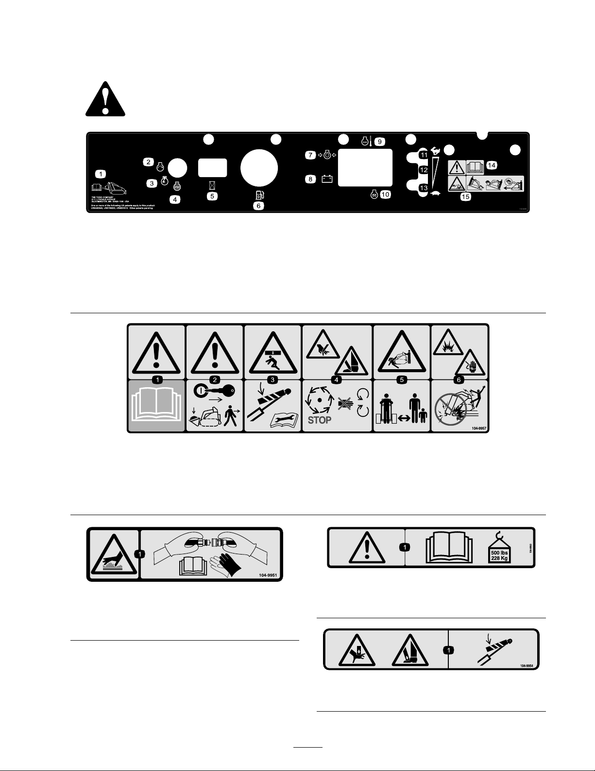
104-9951
1. Hot surface/burn hazard—wear protective gloves when
handling the hydraulic couplers and read the Operator’s
Manual for information on handling hydraulic components.
1. Warning—read the Operator’s Manual ; maximum load rating
of 500 lb. (228 Kg).
1. Crushing hazard of hands or feet—install the cylinder lock.
104-9950
104-9954
9
Page 10
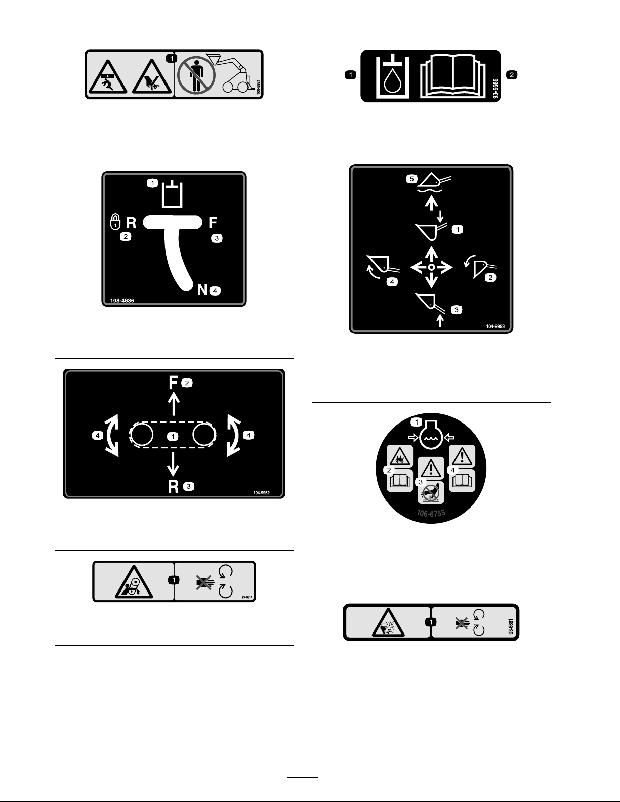
100-8821
1. Crushing hazard and cutting hazard of hand—stay a safe
distance from the front of the traction unit when the loader
arms are raised.
108-4636
1. Auxiliary hydraulics 3. Forward
2. Locked reverse (detent) 4. Neutral (off)
93-6686
1. Hydraulic oil
2. Read the Operator’s Manual.
104-9953
1. Lower the loader arms. 4. Curl the bucket.
2. Dump the bucket. 5. Float the bucket on the
ground.
3. Raise the loader arms.
104-9952
1. Traction Control
2. Forward 4. Turn right or left
3. Reverse
93-7814
1. Entanglement hazard, belt—stay away from moving parts.
106-6755
1. Engine coolant under
pressure.
2. Explosion hazard—read the
Operator’s Manual.
3. Warning—do not touch the
4. Warning—read the
93-6681
1. Cutting/dismemberment—hazard, fan-stay away from
moving parts.
10
hot surface.
Operator’s Manual.
Page 11
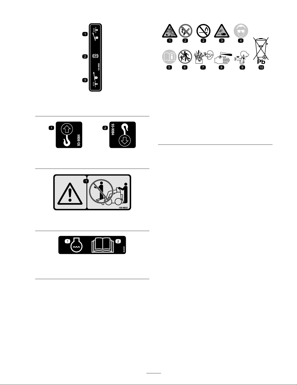
104-9958
1. Disengaged 3. Engaged
2. Parking brake
93-9084
1. Lift point 2. Tie-down point
100-8822
1. Warning—do not carry passengers.
Battery Symbols
Some or all of these symbols are on your battery
1. Explosion hazard 6. Keep bystanders a safe
2. No re, open ame, or
smoking.
3. Caustic liquid/chemical
burn hazard
4. Wear eye protection
5. Read the Operator’s
Manual.
distance from the battery.
7. Wear eye protection;
explosive gases can cause
blindness and other injuries
8. Battery acid can cause
blindness or severe burns.
9. Flush eyes immediately
with water and get medical
help fast.
10. Contains lead; do not
discard.
1. Engine coolant
93-9404
2. Read the Operator’s
Manual.
11
Page 12
Setup
Step
1
Activating the Battery
Parts needed for this step:
80
ounces
Procedure
Batter y posts, ter minals, and r elated
accessories contain lead and lead
compounds, chemicals kno wn to the State of
Calif or nia to cause cancer and r epr oducti v e
har m. W ash hands after handling .
Bulk electrolyte with 1.265 specic gravity
(Purchase from a battery supply outlet.)
Warning
CALIFORNIA
Pr oposition 65 W ar ning
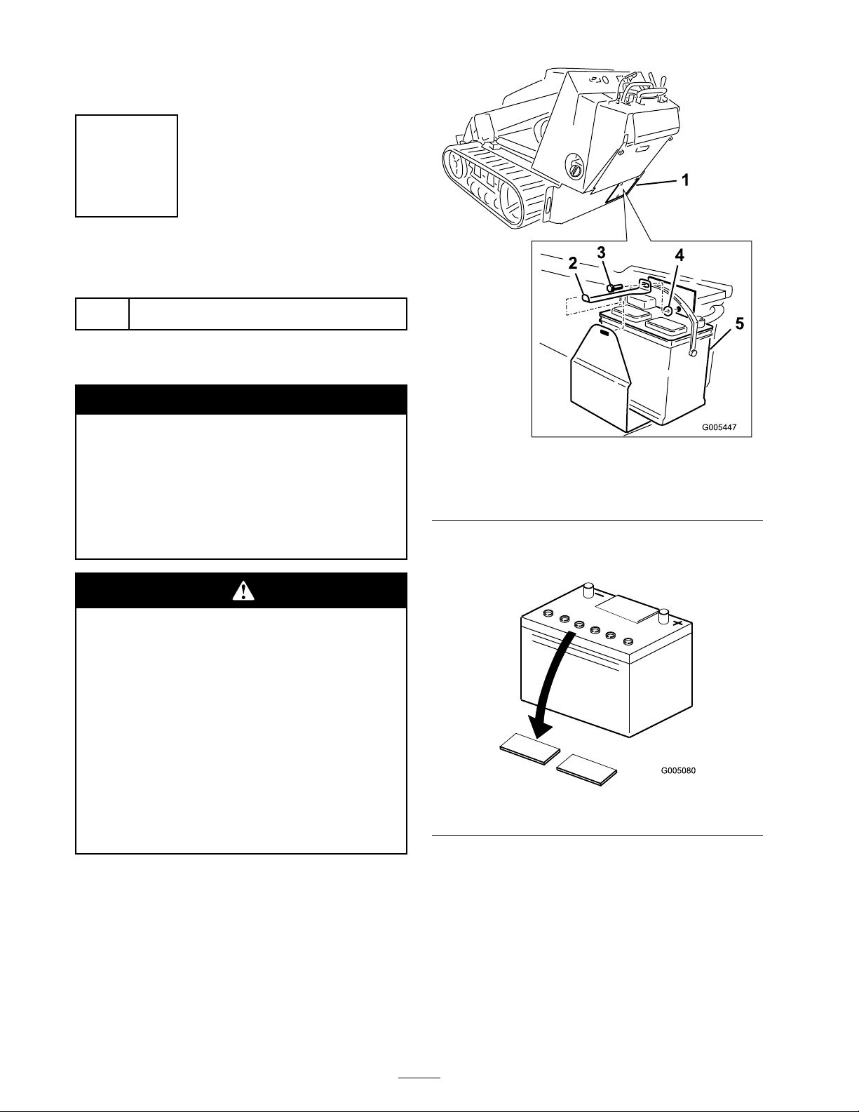
Figure 2
1. Battery access panel 4. Washer
2. Battery clamp
3. Bolt
3. Clean the top of the batter y and remo v e the
v ent caps ( Figure 5 ).
5. Battery
Batter y electr ol yte contains sulfuric acid
which is a deadl y poison and causes sev er e
bur ns.
Do not drink electr ol yte and a v oid contact
with skin, ey es or clothing . W ear safety
g lasses to shield y our ey es and r ub ber g lo v es
to pr otect y our hands.
Fill the batter y wher e clean w ater is al w ays
a v aila ble f or flushing the skin.
F ollo w all instr uctions and compl y with all
safety messa ges on the electr ol yte container .
1. R emo v e the batter y access co v er ( Figure 2 ).
2. R emo v e the batter y from the mac hine
( Figure 2 ).
Important: Nev er fill the batter y with
electr ol yte while the batter y is installed on
the machine. Electr ol yte can be spilled on
other par ts and cause cor r osion.
Figure 3
4. Slo wly pour electrolyte into eac h batter y cell
until the lev el is up to the upper line on the
batter y case .
Important: Do not o v erfill the batter y
because electr ol yte (sulfuric acid) can
cause sev er e cor r osion and dama ge to the
chassis.
12
Page 13
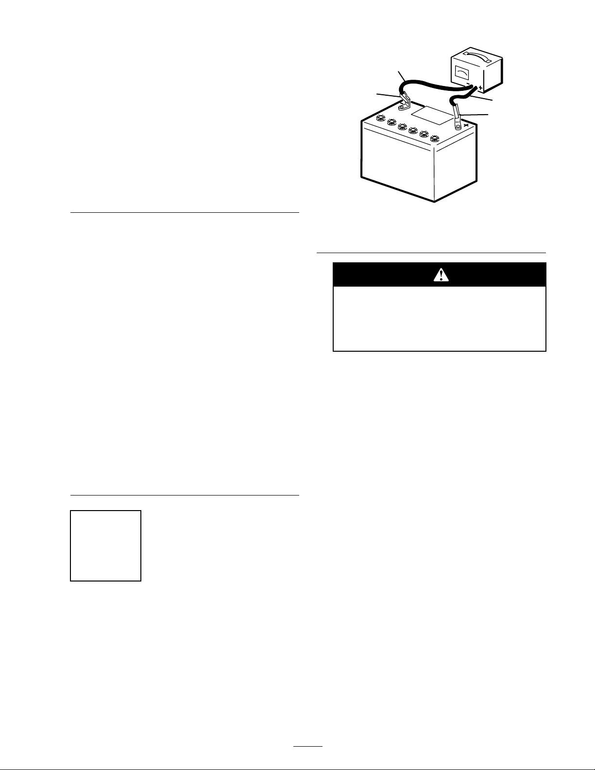
Figure 4
1
2
3
4
G003792
5. W ait fiv e to ten min utes after filling the batter y
cells . Add electrolyte , if necessar y , until the
electrolyte lev el is up to the upper line on the
batter y case .
6. Install the batter y v ent caps ( Figure 5 ).
Figure 5
1. Fill caps 3. Lower line
2. Upper line
Figure 6
1. Positive post
2. Negative post
Charging the batter y pr oduces gasses
that can explode.
Nev er smok e near the batter y and k eep
spar ks and flames a w ay fr om batter y .
2. W hen the batter y is fully c harg ed, unplug
the c harg er from the electrical outlet, then
disconnect the c harg er leads from the batter y
posts ( Figure 6 ).
3. Install the batter y into the mac hine ( Figure 7 ).
4. Install the batter y access co v er ( Figure 7 ).
3. Charger red (+) wire
4. Charger black (—) wire
Step
2
Charging the Battery
No Parts Required
Procedure
1. Connect a c harg er to the batter y ( Figure 6 ) and
c harg e it for a minim um of 1 hour at 6 to 10
amps . Do not o v erc harg e the batter y .
13
Page 14
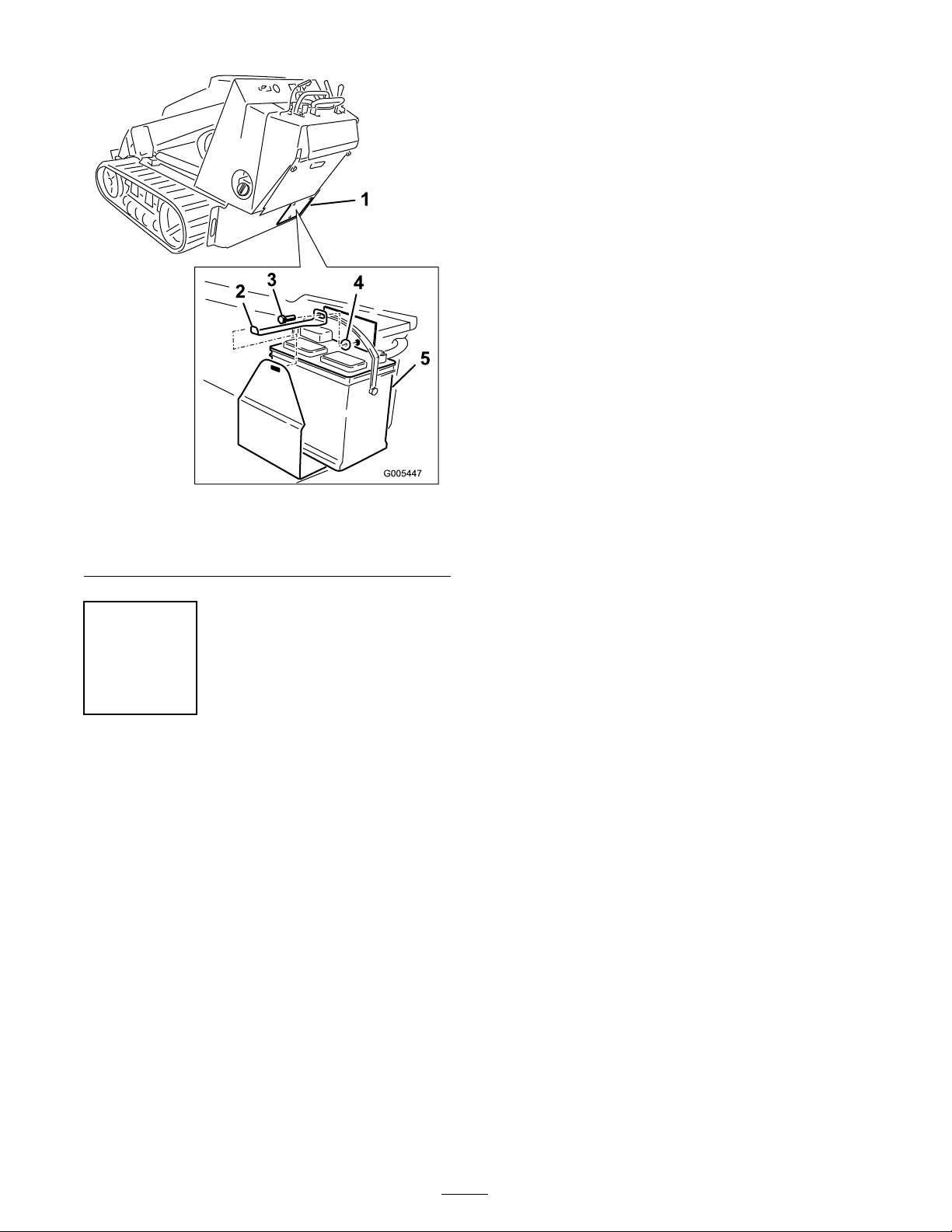
Figure 7
1. Battery access panel 4. Washer
2. Battery clamp
3. Bolt
5. Battery
Step
3
Checking Fluid Levels
No Parts Required
Procedure
Before star ting the engine for the first time , c hec k
the engine oil and h y draulic fluid lev els . R efer to
Operation for more infor mation.
14
Page 15
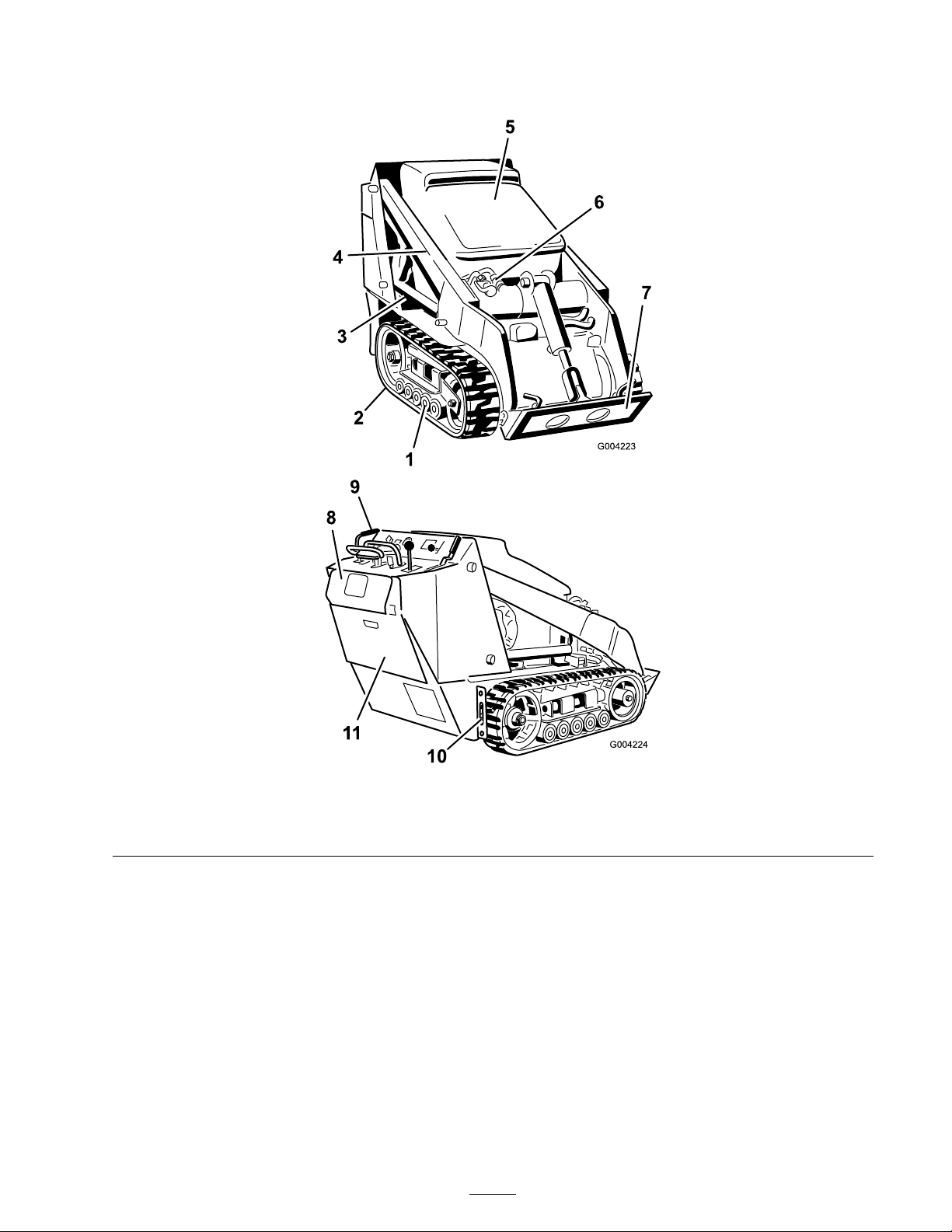
Product Overview
Figure 8
1. Road wheels 4. Loader arms 7. Mount plate 10. Tie-down/lift loop
2. Track 5. Hood 8. Reverse safety plate
3. Lift cylinder 6. Auxiliary hydraulic couplers 9. Control panel
15
11. Rear access cover
Page 16
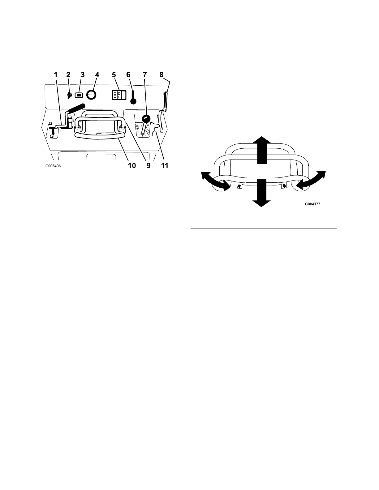
Controls
Traction Control
Become familiar with all the controls ( Figure 9 )
before y ou star t the engine and operate the traction
unit.
Figure 9
1. Auxiliary hydraulics lever 7. Loader arm/attachment tilt
2. Key switch 8. Parking brake lever
3. Hour meter
4. Fuel gauge 10. Traction control
5. Indicator lights and glow
plug switch
6. Throttle lever
lever
9. Reference bar
11. Loader valve lock
T o mo v e forw ard, mo v e the traction control
forw ard. T o mo v e rearw ard, mo v e the traction
control rearw ard ( Figure 10 ).
T o tur n, rotate the traction control in the desired
direction ( Figure 10 ).
T he far ther y ou mo v e the traction control in any
direction, the faster the traction unit will mo v e in
that direction.
T o stop , release the traction control.
Figure 10
Key Switch
T he k ey switc h, used to star t and stop the engine ,
has three positions: off , r un, and star t.
T o star t the engine , rotate the k ey to the star t
position. R elease the k ey when engine star ts and it
will mo v e automatically to the r un position.
T o stop the engine , rotate the k ey to the off
position.
Throttle Lever
Mo v e the control forw ard to increase the engine
speed and rearw ard to decrease speed.
Reference Bar
W hen dri ving the traction unit, use the reference
bar as a handle and a lev erag e point for controlling
the traction control and the auxiliar y h y draulics
lev er . T o ensure smooth, controlled operation, do
not tak e both hands off of the reference bar while
operating the traction unit.
Loader Arm/Attachment Tilt Lever
T o tilt the attac hment forw ard, slo wly mo v e the
lev er to the right ( Figure 11 ).
T o tilt the attac hment rearw ard, slo wly mo v e the
lev er to the left ( Figure 11 ).
T o lo w er the loader ar ms , slo wly mo v e the lev er
forw ard ( Figure 11 ).
T o raise the loader ar ms , slo wly mo v e the lev er
rearw ard ( Figure 11 ).
Y ou can also push the lev er fully forw ard into a
detent position ( Figure 11 ) to release the loader
ar ms so that the attac hment rests on the g round.
T his allo ws attac hments suc h as the lev eler and
the h y draulic blade to follo w the contours of the
g round (i.e ., float) when g rading .
16
Page 17
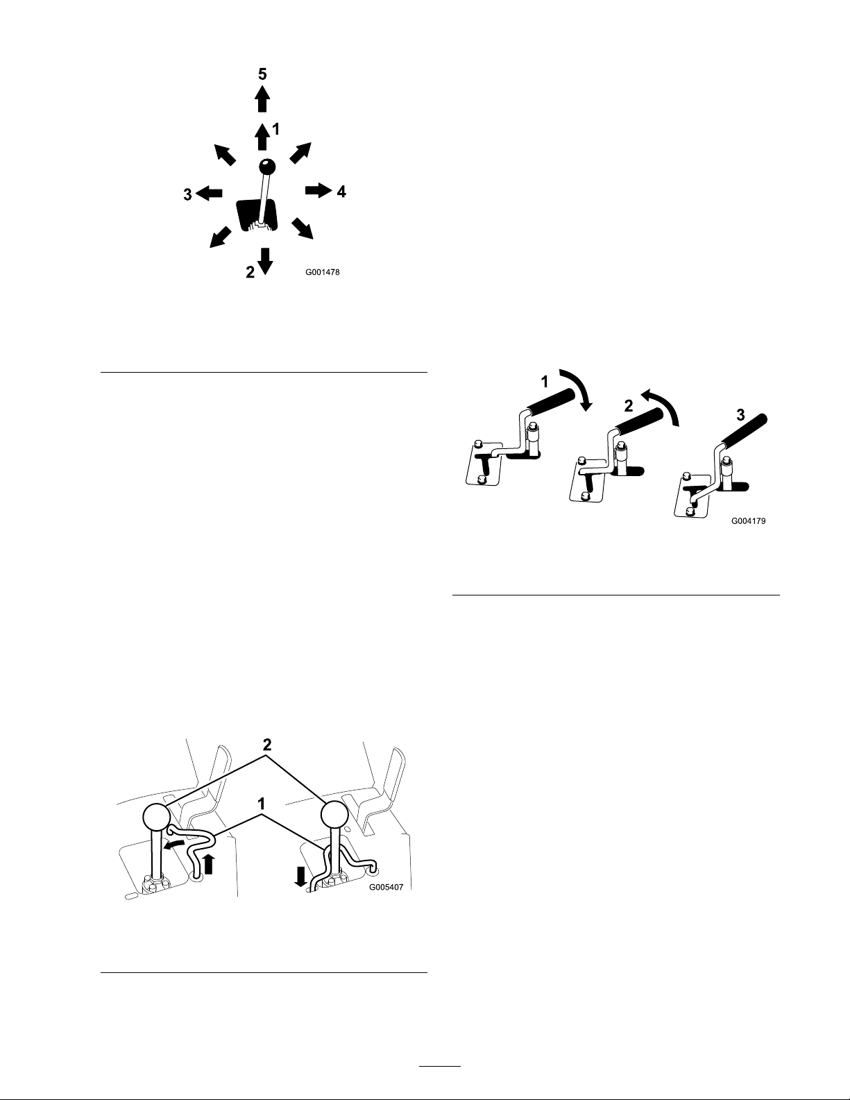
Figure 11
1. Lower the loader arms 4. Tilt the attachment forward
2. Raise the loader arms
3. Tilt the attachment
rearward
5. Detent (Float) position
By mo ving the lev er to an inter mediate position
(suc h as , forw ard and left), y ou can mo v e the
loader ar ms and tilt the attac hment at the same
time .
Auxiliary Hydraulics Lever
T o operate a h y draulic attac hment in the forw ard
direction, rotate the auxiliar y h y draulics lev er
rearw ard and pull it do wn to the reference bar
( Figure 13 , n umber 1).
T o operate a h y draulic attac hment in rev erse
direction, rotate the h y draulics lev er rearw ard, then
mo v e it left into the upper slot ( Figure 13 , n umber
2).
If y ou release the lev er while in the forw ard
position, the lev er will automatically retur n to the
neutral position ( Figure 13 , n umber 3). If it is in
the rev erse position, it will remain there until y ou
pull it out of the slot.
Loader Valve Lock
T he loader v alv e loc k secures the loader
ar m/attac hment tilt lev er so that y ou cannot push
it forw ard. T his helps to ensure that no one
will accidentally lo w er the loader ar ms during
maintenance . Secure the loader ar ms with the loc k
anytime y ou need to stop the mac hine with the
loader ar ms raised.
T o set the loc k, lift up on it so it clears the hole in
the control panel and swing it to the left in front
of the loader ar m lev er , pushing it do wn into the
loc k ed position ( Figure 12 ).
Figure 13
1. Forward ow hydraulics 3. Neutral
2. Reverse ow hydraulics
Parking Brake Lever
T o set the parking brak e , push the brak e lev er
forw ard and to the left and then pull it rearw ard
( Figure 14 ).
Note: T he traction unit ma y roll slightly before
the brak es eng ag e in the dri v e sproc k et.
Figure 12
1. Loader valve lock 2. Loader arm/attachment tilt
lever
17
Page 18

Figure 14
T o release the brak e , push the lev er forw ard and
then right, into the notc h.
Fuel Gauge
T his g aug e measures the amount of fuel in the fuel
tank.
Figure 15
1. Engine oil pressure light 4. Battery charge indicator
2. Engine coolant
temperature light
3. Glow plug switch
light
5. Glow plug light
Engine Oil Pressure Light
If the engine oil pressure g ets too lo w , this light
illuminates and an audible alar m sounds . If this
happens , stop the engine immediately and c hec k
the oil. If lo w , add oil and/or look for possible
leaks .
Battery Charge Indicator Light
If the batter y c harg e becomes too lo w , this light
illuminates and an audible alar m sounds . If this
happens , stop the engine and c harg e or re place the
batter y . Chec k the tension of the alter nator belt;
refer to y our Engine Operator’ s Manual .
Engine Coolant Temperature Light
If the engine coolant g ets too hot, this light
illuminates and an audible alar m sounds . If this
happens , stop the engine and allo w the traction
unit to cool. Chec k the coolant lev el when the
engine has fully cooled.
Glow Plug Light
Illuminates while the glo w plugs are c harg ed and
w ar ming the engine .
Glow Plug Switch
Press and hold this switc h for 10 seconds to
acti v ate the glo w plugs before star ting the engine .
Hour Meter
T he hour meter displa ys the n umber of hours of
operation that ha v e been log g ed on the traction
unit.
18
Page 19

Specications
Note: Specifications and design are subject to c hang e without notice .
Model 22333
Width
Length
Height
Weight
34 inches (86 cm)
71 inches (180 cm)
43 inches (109 cm)
1950 lb (885 Kg)
Operating capacity
Tipping capacity
Wheelbase
Dump height (with narrow bucket) 47 inches (119 cm)
Reach—fully raised (with narrow bucket) 22 inches (55 cm)
Height to hinge pin (narrow bucket in highest position) 66 inches (168 cm)
Model 22334
Width
Length
Height
Weight
Operating capacity
Tipping capacity
553 lb (251 Kg)
1580 lb (717 Kg)
31.2 inches (79 cm)
41 inches (104 cm)
71 inches (180 cm)
43 inches (109 cm)
2050 lb (885 Kg)
553 lb (251 Kg)
1580 lb (717 Kg)
Wheelbase
Dump height (with narrow bucket) 47 inches (119 cm)
Reach—fully raised (with narrow bucket) 22 inches (55 cm)
Height to hinge pin (narrow bucket in highest position) 66 inches (168 cm)
31.2 inches (79 cm)
Attachments/Accessories
A selection of T oro appro v ed attac hments and accessories are a v ailable for use with the mac hine to
enhance and expand its capabilities . Contact y our A uthorized Ser vice Dealer or Distributor or g o to
www .T oro .com for a list of all appro v ed attac hments and accessories .
Important: Use onl y T or o appr o v ed attachments. Other attachments may cr eate an unsafe
operating en vir onment or dama ge the traction unit.
19
Page 20

Stability Data
T he follo wing tables list the maxim um slope recommended for the traction unit in the positions listed in
the tables . Slopes o v er the listed deg ree ma y cause the traction unit to become unstable . T he data in the
tables assume that the loader ar ms are fully lo w ered; raised ar ms ma y affect the stability .
In eac h attac hment man ual is a set of three stability ratings , one for eac h hill position. T o deter mine the
maxim um slope y ou can tra v erse with the attac hment installed, find the deg ree of slope that cor responds
to the stability ratings of the attac hment. Example: If the attac hment installed on a TX model 22319
traction unit has a F ront Uphill rating of B , a R ear Uphill rating of D , and a Side Uphill rating of C ,
then y ou could dri v e forw ard up a 19° slope , rearw ard up a 12° slope , or sidew a ys on a 14° slope , as
listed in the follo wing table .
Model 22333
Conguration
Traction unit without attachment
Traction unit with an attachment rated with one of the following
stability ratings for each slope position:*
A
B
C
D
E
Maximum Recommended Slope when
Front Uphill Rear Uphill Side Uphill
11° 21° 19°
25° 25° 20°
19° 19° 18°
16° 15° 14°
10° 12° 9°
5° 5° 5°
Operating with:
Model 22334
Conguration
Traction unit without attachment
Traction unit with an attachment rated with one of the following
stability ratings for each slope position:*
A
B
C
D
E
Maximum Recommended Slope when
Operating with:
Front Uphill Rear Uphill Side Uphill
12° 19° 21°
25° 25° 23°
22° 22° 20°
18° 16° 14°
10° 10° 10°
5° 5° 5°
20
Page 21

Operation
Note: Deter mine the left and right sides of the
mac hine from the nor mal operating position.
Important: Bef or e operating , check the
fuel and oil lev el, and r emo v e de bris fr om the
traction unit. Also, ensur e that the ar ea is clear
of people and de bris. Y ou should also kno w
and ha v e mar k ed the locations of all utility
lines.
Filling the Fuel Tank
1. R emo v e the fuel tank cap ( Figure 16 ).
Under cer tain conditions, diesel fuel and
fuel v apor s ar e highl y flamma ble and
explosi v e. A fir e or explosion fr om fuel
can bur n y ou and other s and can cause
pr oper ty dama ge.
• Use a funnel and fill the fuel tank
outdoor s, in an open ar ea, when the
engine is of f and is cold. W ipe up an y
fuel that spills.
• Do not fill the fuel tank completel y
full. Add fuel to the fuel tank until the
lev el is 1/4 to 1/2 inch (6 to 13 mm)
belo w the bottom of the filler neck.
T his empty space in the tank allo ws
the fuel to expand.
• Nev er smok e when handling fuel,
and stay a w ay fr om an open flame or
wher e fuel fumes may be ignited by
a spar k.
• Stor e fuel in a clean, safety-appr o v ed
container and k eep the cap in place.
Figure 16
1. Fuel tank cap
2. Fill the tank to about one inc h belo w the top
of the tank, not the filler nec k, with No . 2
diesel fuel.
3. Install the fuel tank cap .
Checking the Engine Oil
Level
1. P ark the traction unit on a lev el surface , lo w er
the loader ar ms , and stop the engine .
2. R emo v e the k ey and allo w the engine to cool.
3. Open the hood.
4. Clean around the oil dipstic k ( Figure 17 ).
21
Page 22

Figure 17
1. Oil dipstick 2. Oil ller cap
5. Pull out the dipstic k and wipe the metal end
clean ( Figure 17 ).
2. P ark the traction unit on a lev el surface ,
lo w er the loader ar ms , and fully retract the tilt
cylinder .
3. Stop the engine , remo v e the k ey , and allo w the
engine to cool.
4. Open the hood.
5. Clean the area around the filler nec k of the
h y draulic tank ( Figure 18 ).
6. Slide the dipstic k fully into the dipstic k tube
( Figure 17 ).
7. Pull the dipstic k out and look at the metal end.
8. If the oil lev el is lo w (belo w the bottom hole),
clean around the oil filler cap and remo v e the
cap ( Figure 17 ).
9. Slo wly pour only enough oil into the v alv e
co v er to raise the lev el to the top hole on the
dipstic k.
Important: Do not o v erfill the crankcase
with oil because the engine may be
dama ged.
10. R e place the filler cap and dipstic k.
11. Close the hood.
Checking the Hydraulic
Fluid Level
Chec k the h y draulic fluid lev el before the engine is
first star ted and after ev er y 25 operating hours .
Figure 18
1. Hydraulic ller neck cap
6. R emo v e the cap from the filler nec k and c hec k
the fluid lev el on the dipstic k ( Figure 19 ).
T he fluid lev el should be betw een the marks
on the dipstic k.
Hy draulic T ank Capacity: 12 US g allons (45.4 l)
Use 10W -30 deterg ent, diesel engine oil (API
ser vice CH-4 or higher).
1. R emo v e the attac hment, if one is installed;
refer to R emo ving an Attac hment.
22
Page 23

If the engine has been r unning , the
pr essuriz ed, hot coolant can escape and
cause sev er e bur ns.
• Do not r emo v e the radiator cap when
the engine is hot. Al w ays allo w the
engine to cool at least 15 min utes or
until the radiator cap is cool enough to
touch without bur ning y our hand bef or e
r emo ving the radiator cap .
• Do not touch radiator and sur r ounding
par ts that ar e hot.
Figure 19
1. Filler neck 2. Dipstick
7. If the lev el is lo w , add enough fluid to raise it
to the proper lev el.
8. Install the cap on the filler nec k.
9. Close the hood.
Checking, Adding, and
Bleeding the Engine Coolant
Clean debris off of the screen, oil cooler , and front
of the radiator daily and more often if conditions
are extremely dusty and dir ty
T he cooling system is filled with a 50/50 solution
of w ater and per manent eth ylene glycol antifreeze .
Chec k the lev el of coolant in the expansion tank
at the beginning of eac h da y before star ting the
engine .
• Use a ra g when opening the radiator cap ,
and open the cap slo wl y to allo w steam
to escape.
R otating shaft and f an can cause per sonal
injur y .
• Do not operate the machine without the
co v er s in place.
• K eep finger s, hands and clothing clear of
r otating f an and dri v e shaft.
• Shut of f the engine and r emo v e
the ignition k ey bef or e perf or ming
maintenance.
Sw allo wing engine coolant can cause
poisoning .
• Do not s w allo w engine coolant.
• K eep out of r each of childr en and pets.
1. Chec k the lev el of coolant in the expansion
tank ( Figure 20 ).
T he coolant lev el should be at or abo v e the
mark on the side of the tank.
23
Page 24

E. P our coolant into the coolant filler nec k
until the coolant begins to come out of the
top coolant bleed v alv e ( Figure 21 ).
F . Close the top coolant bleed v alv e
( Figure 21 ).
G . P our coolant into the coolant filler nec k
until the coolant lev el comes into the filler
nec k ( Figure 21 ).
H. Install the coolant fill cap ( Figure 21 ).
I. Add coolant into the expansion tank until
it reac hes the Full line on the side of the
tank ( Figure 21 ).
3. Install the expansion tank cap .
Figure 20
1. Expansion tank
2. Full mark
2. If the coolant lev el is lo w , complete the
follo wing procedure:
A. R emo v e the coolant fill cap ( Figure 21 ).
Figure 21
1. Expansion tank 3. Top coolant bleed valve
2. Coolant ll cap and ller
neck
4. Front coolant bleed valve
B . Open the front and top coolant bleed
v alv es ( Figure 21 ).
C . P our coolant into the coolant filler nec k
until the coolant begins to come out of the
front coolant bleed v alv e ( Figure 21 ).
D . Close the front coolant bleed v alv e
( Figure 21 ).
Bleeding the Fuel System
Y ou m ust bleed the fuel system before star ting
the engine if any of the follo wing situations ha v e
occur red:
• Initial star t up of a new mac hine .
• Engine has ceased r unning due to lac k of fuel.
• Maintenance has been perfor med upon fuel
system components (e .g ., filter re placed).
Under cer tain conditions, diesel fuel and fuel
v apor s ar e highl y flamma ble and explosi v e.
A fir e or explosion fr om fuel can bur n y ou
and other s and can cause pr oper ty dama ge.
• Use a funnel and fill the fuel tank
outdoor s, in an open ar ea, when the
engine is of f and is cold. W ipe up an y
fuel that spills.
• Do not fill the fuel tank completel y full.
Add fuel to the fuel tank until the lev el
is 1/4 to 1/2 in. (6 to 13 mm) belo w the
bottom of the filler neck. T his empty
space in the tank allo ws the fuel to
expand.
• Nev er smok e when handling fuel, and
stay a w ay fr om an open flame or wher e
fuel fumes may be ignited by a spar k.
• Stor e fuel in a clean, safety-appr o v ed
container and k eep the cap in place.
1. Ensure that the fuel tank is at least half full.
24
Page 25

2. Open the hood.
3. Open the air bleed screw on the fuel injection
pump ( Figure 22 ).
5. T ur n the ignition k ey to the Star t position.
W hen the engines star ts , release the k ey .
Important: Do not enga ge the star ter
f or mor e than 10 seconds at a time. If the
engine f ails to star t, allo w a 30 second
cool-do wn period betw een attempts.
F ailur e to f ollo w these instr uctions can
bur n out the star ter motor .
6. Mo v e the throttle lev er to desired setting .
Important: If the engine is r un at high
speeds when the h y draulic system is cold
(i.e., when the ambient air temperatur e is
near fr eezing or lo w er), h y draulic system
dama ge could occur . W hen star ting the
engine in cold conditions, allo w the engine
to r un in the middle thr ottle position f or
2 to 5 min utes bef or e mo ving the thr ottle
to f ast (ra b bit).
Figure 22
1. Fuel injection pump bleed screw
4. T ur n the k ey in the ignition switc h to the On
position. T he electric fuel pump will begin
operation, thereb y forcing air out around
the air bleed screw . Lea v e the k ey in the On
position until a solid stream of fuel flo ws out
around the screw .
5. Tighten the screw and tur n the k ey to the Off
position.
Note: Nor mally , the engine should star t after the
abo v e bleeding procedures are follo w ed. Ho w ev er ,
if engine does not star t, air ma y be trapped
betw een injection pump and injectors; contact
y our A uthorized Ser vice Dealer .
Starting and Stopping the
Engine
Starting the Engine
Note: If outdoor temperature is belo w
freezing, store the traction unit in a g arag e to
k ee p it w ar mer and aid in star ting .
Stopping the Engine
1. Mo v e the throttle lev er to the slo w (tur tle)
position.
2. Lo w er the loader ar ms to the g round.
3. T ur n the ignition k ey off .
Note: If the engine has been w orking hard or
is hot, let it idle for a min ute before tur ning
the ignition k ey off . T his helps cool the engine
before it is stopped. In an emerg ency , the
engine ma y be stopped immediately .
Stopping the Traction Unit
T o stop the traction unit, release the traction
control, mo v e the throttle lev er to slo w (tur tle),
lo w er loader ar ms to the g round, and stop the
engine . Set the parking brak e and remo v e the k ey .
1. Ensure that the auxiliar y h y draulics lev er is in
neutral.
2. Mo v e the throttle lev er midw a y betw een slo w
(tur tle) and fast (rabbit) positions .
3. T ur n the ignition k ey to the R un position.
4. Press the glo w plug switc h and hold it for 10
seconds .
A child or untrained bystander could attempt
to operate the traction unit and be injur ed.
R emo v e the k ey fr om the s witch when
lea ving the traction unit, ev en if just f or a
few seconds.
25
Page 26

Moving a Non-functioning
Traction Unit
Important: Do not to w or pull the traction
unit without fir st opening the to w v alv es, or
the h y draulic system will be dama ged.
1. Stop the engine .
2. Open the rear access co v er .
3. Using a wrenc h, tur n the to w v alv es on the
h y draulic pumps twice counter -cloc kwise
( Figure 23 ).
2. Raise the loader ar ms to the fully raised
position.
3. Stop the engine .
4. R emo v e the hair pin cotter and clevis pin
securing the cylinder loc k to the loader ar m
( Figure 24 ).
Figure 24
1. Cylinder lock 3. Clevis pin
2. Lift cylinder
4. Hairpin cotter
Figure 23
1. Left tow valve (right track) 2. Right tow valve (left track)
4. T o w the traction unit as required.
5. W hen the traction unit has been re paired, close
the to w v alv es before operating it.
Using the Cylinder Lock
T he loader ar ms may lo w er when in the
raised position cr ushing an y one under them.
Install the cylinder lock bef or e perf or ming
maintenance that r equir es raised loader
ar ms.
5. Lo w er the cylinder loc k o v er the cylinder rod
and secure it with the clevis pin and hair pin
cotter ( Figure 24 ).
6. Slo wl y lo w er the loader ar ms until cylinder
loc k contacts the cylinder body and rod end.
Removing/Storing the Cylinder Lock
Important: Ensur e that the cylinder lock is
r emo v ed fr om the r od and full y secur ed in the
stora ge position bef or e operating the traction
unit.
1. Star t the engine .
2. Raise the loader ar ms to the fully raised
position.
3. Stop the engine .
4. R emo v e the clevis pin and cotter pin securing
the cylinder loc k.
5. R otate the cylinder loc k up to the loader ar m
and secure it with the clevis pin and hair pin
cotter .
Installing the Cylinder Lock
1. R emo v e the attac hment.
6. Lo w er the loader ar ms .
26
Page 27

Using Attachments
Important: If y ou ar e using an attachment
with a serial n umber of 200999999 or ear lier ,
the man ual f or the attachment may contain
inf or mation specific to the use of the
attachment with other compact utility loader
models, such as settings f or the flo w di vider
contr ol and speed selector lev er and the use of
a counterw eight on the traction unit. T hese
systems ar e built into the TX, and y ou should
ignor e an y r efer ences to them.
Installing an Attachment
Important: Use onl y T or o-appr o v ed
attachments. Attachments can change the
sta bility and the operating characteristics of
the traction unit. T he w ar ranty of the traction
unit may be v oided if used with unappr o v ed
attachments.
Important: Bef or e installing the
attachment, ensur e that the mount plates ar e
fr ee of an y dir t or de bris and that the pins
r otate fr eel y . If the pins do not r otate fr eel y ,
g r ease them.
Important: T he attachment should be
raised enough to clear the g r ound, and the
mount plate should be tilted all the w ay
back.
6. Stop the engine .
7. Eng ag e the quic k attac h pins , ensuring that
they are fully seated in the mount plate
( Figure 26 ).
Important: If the pins do not r otate to
the enga ged position, the mount plate
is not full y aligned with the holes in the
attachment r ecei v er plate. Check the
r ecei v er plate and clean it if necessar y .
1. P osition the attac hment on a lev el surface with
enough space behind it to accommodate the
traction unit.
2. Star t the engine .
3. Tilt the attac hment mount plate forw ard.
4. P osition mount plate into the upper lip of the
attac hment recei v er plate ( Figure 25 ).
Figure 25
1. Mount plate 2. Receiver plate
5. Raise the loader ar ms while tilting bac k the
mount plate at the same time .
Figure 26
1. Quick attach pins (shown
in engaged position)
2. Disengaged position
3. Engaged position
If y ou do not full y seat the quick attach
pins thr ough the attachment mount
plate, the attachment could f all of f of the
traction unit, cr ushing y ou or bystander s.
Ensur e that y our quick attach pins ar e
full y seated in the attachment mount
plate.
27
Page 28

Connecting the Hydraulic Hoses
If the attac hment requires h y draulics for operation,
connect the h y draulic hoses as follo ws:
1. Stop the engine .
2. Mo v e the auxiliar y h y draulics lev er forw ard,
bac kw ard, and bac k to neutral to reliev e
pressure at the h y draulic couplers .
3. Mo v e the auxiliar y h y draulics lev er into the
rev erse position.
4. R emo v e the protecti v e co v ers from the
h y draulic couplers on the traction unit.
5. Ensure that all foreign matter is cleaned from
the h y draulic connectors .
6. Push the attac hment male connector into the
female connector on the traction unit.
Note: W hen y ou connect the attac hment
male connector first, y ou will reliev e any
pressure built up in the attac hment.
8. Confir m that the connection is secure b y
pulling on the hoses .
9. Mo v e the auxiliar y h y draulics lev er to neutral.
Removing an Attachment
1. Lo w er the attac hment to the g round.
2. Stop the engine .
3. Diseng ag e the quic k attac h pins b y tur ning
them to the outside .
4. If the attac hment uses h y draulics , mo v e the
auxiliar y h y draulics lev er forw ard, bac kw ard,
and bac k to neutral to reliev e pressure at the
h y draulic couplers .
5. If the attac hment uses h y draulics , slide the
collar bac k on the h y draulic couplers and
disconnect them.
Important: Connect the attachment
hoses to gether to pr ev ent h y draulic system
contamination during stora ge.
Hy draulic fluid escaping under pr essur e
can penetrate skin and cause injur y .
F luid injected into the skin must be
surgicall y r emo v ed within a few hour s by
a doctor f amiliar with this f or m of injur y
or gang r ene may r esult.
• K eep y our body and hands a w ay fr om
pin hole leaks or nozzles that eject
high pr essur e h y draulic fluid.
• Use cardboard or paper to find
h y draulic leaks, nev er use y our hands.
Hy draulic coupler s, h y draulic
lines/v alv es, and h y draulic fluid may be
hot. If y ou contact hot components y ou
may be bur ned.
• W ear g lo v es when operating the
h y draulic coupler s.
• Allo w the traction unit to cool bef or e
touching h y draulic components.
• Do not touch h y draulic fluid spills.
7. Push the attac hment female connector into the
male connector on the traction unit.
6. Install the protecti v e co v ers onto the h y draulic
couplers on the traction unit.
7. Star t the engine , tilt the mount plate forw ard,
and bac k the traction unit a w a y from the
attac hment.
Securing the Traction Unit
for Transport
W hen transpor ting the traction unit on a trailer ,
alw a ys use the follo wing procedure:
Important: Do not operate or dri v e the
traction unit on r oad w ays.
1. Lo w er the loader ar ms .
2. Stop the engine .
3. Secure the traction unit to the trailer with
c hains or straps using the tie-do wn/lift loops
( Figure 8 ) to secure the rear of the traction unit
and the loader ar ms/mount plate to secure the
front of the traction unit.
Lifting the Traction Unit
Y ou can lift the traction unit using the tie-do wn/lift
loops as lift points ( Figure 8 ).
28
Page 29

Maintenance
Note: Deter mine the left and right sides of the mac hine from the nor mal operating position.
Recommended Maintenance Schedule(s)
Maintenance Service
Interval
After the rst 8 operating
hours
After the rst 50
operating hours
Before each use or daily
Every 25 hours
Every 100 hours
Maintenance Procedure
• Replace the hydraulic lter.
• Change the engine oil.
• Change the oil lter.
• Check and adjust the track tension.
• Check the engine oil level.
• Check the cooling system.
• Grease the traction unit.
• Drain water and other contaminants from the fuel lter/water separator.
• Check the condition of and clean the tracks.
• Clean the radiator.
• Remove debris from the traction unit.
• Check for loose fasteners.
• Check the hydraulic uid level.
• Change the engine oil (more frequently when operating conditions are
extremely dusty or sandy).
• Check the battery electrolyte level (replacement battery only).
• Check the battery cable connections.
• Check and adjust the track tension.
• Check the cooling system hoses.
• Check the alternator/fan belt tension (refer to the Engine Operator’s
Manual for instructions).
• Check the hydraulic lines for leaks, loose ttings, kinked lines, loose
mounting supports, wear, weather, and chemical deterioration.
• Check for dirt build-up in the chassis.
Every 200 hours
Every 250 hours
Every 400 hours
Every 500 hours
Every 600 hours
Every 1,500 hours
• Replace the primary air lter.
• Change the oil lter (more frequently when operating conditions are
extremely dusty or sandy).
• Replace the hydraulic lter.
• Check and grease the road wheels.
• Check the fuel lines and connections for deterioration, damage, or loose
connections.
• Replace the fuel lter canister.
• Change the hydraulic uid.
• Replace the alternator/fan belt (refer to the Engine Operator’s Manual
for instructions).
• Replace the safety air lter.
• Replace all moving hydraulic hoses.
Yearly
• Change the engine coolant (Authorized Service Dealer only).
• Check the condition of the hydraulic pump belt.
29
Page 30

Maintenance Service
Interval
Maintenance Procedure
Yearly or before storage
Every 2 years
Important: R efer to y our Engine Operator’ s Man ual f or additional maintenance pr ocedur es.
If y ou lea v e the k ey in the ignition s witch, someone could accidentl y star t the engine and
seriousl y injur e y ou or other bystander s.
R emo v e the k ey fr om the ignition bef or e y ou do an y maintenance.
• Check and adjust the track tension.
• Touch up chipped paint
• Drain and clean the fuel tank (Authorized Service Dealer only).
Premaintenance
Procedures
Before opening any of the co v ers , stop the engine
and remo v e the k ey . Allo w the engine to cool
before opening any co v ers
Opening the Hood
1. Push do wn on the hood while using a coin or
screw dri v er to tur n the hood latc h cloc kwise
( Figure 27 ).
Figure 27
1. Hood, push down 2. Hood latch, turn clockwise
2. Swing the hood up ( Figure 28 ).
Figure 28
1. Hood, swing up
Closing the Hood
Lo w er the hood and secure it b y pushing do wn on
the front of the hood until it loc ks in place .
Opening the Rear Access
Cover
1. Unscrew the 2 hand knobs securing the rear
access co v er to the mac hine ( Figure 29 ).
30
Page 31

Figure 29
1. Hand knob
2. Tilt the rear access co v er do wn and remo v e to
access the inter nal components ( Figure 29 ).
Closing the Rear Access
Cover
Figure 30
1. Side screen
1. Mo v e the rear access co v er in place o v er the
bac k of the traction unit making sure the tabs
line up in the slots .
2. Push the access co v er forw ard, lining up the
hand knob screws with the threaded holes in
the mac hine .
3. Screw the hand knobs tight to secure the rear
access co v er in place .
Removing the Side Screens
1. Open the hood.
2. Slide the side screens ( Figure 30 ) up and out of
the slots in the front screen and frame .
Installing the Side Screens
Slide the side screens into place in the slots in the
front screen and frame .
Lubrication
Greasing the Traction Unit
Grease all pi v ot joints ev er y 8 operating hours and
immediately after ev er y w ashing .
Grease T ype: General-pur pose g rease .
1. Lo w er the loader ar ms and stop the engine .
R emo v e the k ey .
2. Clean the g rease fittings with a rag .
3. Connect a g rease gun to eac h fitting ( Figure 31
and Figure 32 ).
31
Page 32

Figure 31
Replacing the Filters
1. Lo w er the loader ar ms , stop the engine , and
remo v e the k ey .
2. Open the hood.
3. R elease the latc hes on the air cleaner and pull
the air cleaner co v er off of the air cleaner body
( Figure 33 ).
Figure 33
1. Air lter body 4. Air cleaner cover
2. Safety lter 5. Latches
3. Primary lter
6. Dust cap
Figure 32
4. Pump g rease into the fittings until g rease begins
to ooze out of the bearings (appro ximately 3
pumps).
5. Wipe up any ex cess g rease .
Engine Maintenance
Servicing the Air Cleaner
Primar y Filter : R e place after ev er y 200 operating
hours or more often in dusty conditions .
Safety Filter : R e place after ev er y 600 operating
hours .
Note: Ser vice the air cleaner more frequently if
operating conditions are extremely dusty or sandy .
4. Squeeze the dust cap sides to open it and
knoc k the dust out.
5. Clean the inside of the air cleaner co v er with
compressed air .
6. Gently slide the primar y filter out of the air
cleaner body ( Figure 33 ). A v oid knoc king the
filter into the side of the body .
Important: Do not attempt to clean the
primar y filter .
7. R emo v e the safety filter only if y ou intend to
re place it.
Important: Nev er attempt to clean the
safety filter . If the safety filter is dir ty ,
then the primar y filter is dama ged and y ou
should r eplace both filter s.
8. Inspect the new filter(s) for damag e b y looking
into the filter while shining a bright light on
the outside of the filter . Holes in the filter will
appear as bright spots . Inspect the element for
tears , an oily film, or damag e to the r ubber
seal. If the filter is damag ed do not use it.
9. If y ou are re placing the safety filter , carefully
slide the new filter into the filter body
( Figure 33 ).
32
Page 33

Important: T o pr ev ent engine dama ge,
al w ays operate the engine with both air
filter s and co v er installed.
10. Carefully slide the primar y filter o v er the safety
filter ( Figure 33 ). Ensure that it is fully seated
b y pushing on the outer rim of the filter while
installing it.
Important: Do not pr ess on the soft
inside ar ea of the filter .
11. Install the air cleaner co v er with the side
indicated as UP facing up and secure the
latc hes ( Figure 33 ).
12. Close the hood.
Servicing the Engine Oil
Chang e oil and the oil filter after the first 50
operating hours . Chang e the oil ev er y 100
operating hours and the oil filter ev er 200
operating hours thereafter ..
Changing the Oil
1. Star t the engine and let it r un for fiv e min utes .
T his w ar ms the oil so it drains better .
2. P ark the traction unit so that the drain side is
slightly lo w er than the opposite side to ensure
that the oil drains completely .
3. Lo w er the loader ar ms , set the parking brak e ,
stop the engine , and remo v e the k ey .
Components will be hot if the traction
unit has been r unning . If y ou touch hot
components y ou may be bur ned.
Allo w the traction unit to cool bef or e
perf or ming maintenance or touching
components under the hood.
4. R emo v e the drain plug ( Figure 35 ).
Note: Chang e oil and oil filter more frequently
when operating conditions are extremely dusty or
sandy .
Oil T ype: Deterg ent diesel engine oil (API ser vice
CH-4 or higher)
Crankcase Capacity: w/filter , 0.98 US g allons (3.7
l)
Viscosity: See table belo w
Figure 35
1. Oil drain plug
5. W hen the oil has drained completely , re place
the plug .
Note: Dispose of the used oil at a cer tified
recycling center .
Figure 34
6. R emo v e the oil fill cap and slo wly pour
appro ximately 80% of the specified amount of
oil in through the v alv e co v er .
7. Chec k the oil lev el; refer to Chec king the
Engine Oil Lev el in Operation , pag e 21 .
33
Page 34

8. Slo wly add additional oil to bring the lev el to
the upper hole on the dipstic k.
9. R e place the fill cap .
Changing the Oil Filter
1. Drain the oil from the engine; refer to
Changing the Oil.
2. Place a shallo w pan or rag under the filter to
catc h oil.
3. R emo v e the old filter ( Figure 36 ) and wipe the
surface of the filter adapter g ask et.
Fuel System
Maintenance
Under cer tain conditions, diesel fuel and fuel
v apor s ar e highl y flamma ble and explosi v e.
A fir e or explosion fr om fuel can bur n y ou
and other s and can cause pr oper ty dama ge.
• Use a funnel and fill the fuel tank
outdoor s, in an open ar ea, when the
engine is of f and is cold. W ipe up an y
fuel that spills.
• Do not fill the fuel tank completel y full.
Add fuel to the fuel tank until the lev el
is 1/4 to 1/2 in. (6 to 13 mm) belo w the
bottom of the filler neck. T his empty
space in the tank allo ws the fuel to
expand.
• Nev er smok e when handling fuel, and
stay a w ay fr om an open flame or wher e
fuel fumes may be ignited by a spar k.
Figure 36
1. Oil lter
4. P our new oil of the proper type through the
center hole of the filter . Stop pouring when
the oil reac hes the bottom of the threads .
5. Allo w a min ute or tw o for the oil to be
absorbed b y filter material, then pour off the
ex cess oil.
6. Apply a thin coat of new oil to the r ubber
g ask et on the re placement filter .
7. Install the re placement oil filter to the filter
adapter . T ur n the oil filter cloc kwise until the
r ubber g ask et contacts the filter adapter , then
tighten the filter an additional 1/2 tur n.
• Stor e fuel in a clean, safety-appr o v ed
container and k eep the cap in place.
Checking the Fuel Lines and
Connections
Chec k the fuel lines and connections ev er y
400 hours or yearly , whic hev er comes first.
Inspect them for deterioration, damag e , or loose
connections . Tighten any loose connections
and contact y our A uthorized Ser vice Dealer for
assistance in fixing damag ed fuel lines .
Draining the Fuel
Filter/Water Separator
Drain w ater or other contaminants from the fuel
filter/w ater se parator ( Figure 37 ) daily .
8. Fill the crankcase with the proper type of new
oil; refer to Changing the Oil.
34
Page 35

Electrical System
Maintenance
Servicing the Battery
Warning
CALIFORNIA
Pr oposition 65 W ar ning
Batter y posts, ter minals, and r elated
accessories contain lead and lead
compounds, chemicals kno wn to the State of
Calif or nia to cause cancer and r epr oducti v e
har m. W ash hands after handling .
Figure 37
1. Fuel lter canister/water
separator
1. Locate the fuel filter on the right side of the
engine( Figure 37 ) and place a clean container
under it.
2. Loosen the drain plug on the bottom of the
filter canister and allo w it to drain.
3. W hen finished, tighten the drain plug .
2. Drain plug
Replacing the Fuel Filter
Canister
R e place the filter canister after ev er y 400 hours
of operation.
1. Clean the area where the filter canister mounts
( Figure 37 ).
2. R emo v e the filter canister and clean the
mounting surface ( Figure 37 ).
Important: T he f ollo wing pr ocedur es
appl y when ser vicing a (dr y) batter y that has
r eplaced the original batter y . T he original
(w et) batter y does not r equir e ser vice.
Chec k the electrolyte lev el in the batter y ev er y 100
hours . Alw a ys k ee p the batter y clean and fully
c harg ed. Use a paper to w el to clean the batter y
case . If the batter y ter minals are cor roded, clean
them with a solution of four par ts w ater and one
par t baking soda. Apply a light coating of g rease
to the batter y ter minals to reduce cor rosion.
V oltag e: 12 v , 450 Cold Cranking Amps
Checking the Electrolyte Level
1. Stop the engine and remo v e the k ey .
2. Look at the side of the batter y . T he electrolyte
m ust be up to the Upper line ( Figure 38 ).
Do not allo w the electrolyte to fall belo w the
Lo w er line ( Figure 38 ).
3. Lubricate the g ask et on the new filter canister
with clean oil.
4. Install the filter canister b y hand until the
g ask et contacts the mounting surface , then
rotate it an additional 1/2 tur n ( Figure 37 ).
Draining the Fuel Tank
Ha v e an A uthorized Ser vice Dealer drain and
clean the fuel tank ev er y 2 years .
35
Page 36

2
3
1
G003794
Important: Do not o v erfill the batter y
1
2
3
4
G003792
because electr ol yte (sulfuric acid) can
cause sev er e cor r osion and dama ge to the
chassis.
5. W ait fiv e to ten min utes after filling the batter y
cells . Add distilled w ater , if necessar y , until
the electrolyte lev el is up to the Upper line
( Figure 38 ) on the batter y case .
6. Install the batter y filler caps .
Figure 38
1. Filler caps 3. Lower line
2. Upper line
3. If the electrolyte is lo w , add the required
amount of distilled w ater; refer to Adding
W ater to the Batter y .
Adding Water to the Battery
T he best time to add distilled w ater to the batter y
is just before y ou operate the traction unit. T his
lets the w ater mix thoroughly with the electrolyte
solution.
Batter y electr ol yte contains sulfuric acid
which is a deadl y poison and causes sev er e
bur ns.
• Do not drink electr ol yte and a v oid
contact with skin, ey es or clothing . W ear
safety g lasses to shield y our ey es and
r ub ber g lo v es to pr otect y our hands.
Charging the Battery
Charging the batter y pr oduces gasses that
can explode.
Nev er smok e near the batter y and k eep
spar ks and flames a w ay fr om batter y .
Important: Al w ays k eep the batter y
full y charged (1.265 specific g ra vity). T his
is especiall y impor tant to pr ev ent batter y
dama ge when the temperatur e is belo w 32°F
(0°C).
1. Chec k the electrolyte lev el; refer to Chec king
Electrolyte Lev el.
2. Mak e sure the filler caps are installed in the
batter y .
3. Charg e the batter y for 10 to 15 min utes at
25 to 30 amps or 30 min utes at 4 to 6 amps
( Figure 39 ). Do not o v erc harg e the batter y .
• Fill the batter y wher e clean w ater is
al w ays a v aila ble f or flushing the skin.
1. R emo v e the batter y from the traction unit.
Important: Nev er fill the batter y with
distilled w ater while the batter y is installed
in the traction unit. Electr ol yte could be
spilled on other par ts and cause cor r osion.
2. Clean the top of the batter y with a paper to w el.
( Figure 38 ).
4. Slo wly pour distilled w ater into eac h batter y
cell until the electrolyte lev el is up to the Upper
3. R emo v e the filler caps from the batter y
line ( Figure 38 ) on the batter y case .
1. Positive battery post
2. Negative battery post
4. W hen the batter y is fully c harg ed, unplug
the c harg er from the electrical outlet, then
36
Figure 39
3. Red (+) charger lead
4. Black (-) charger lead
Page 37

disconnect the c harg er leads from the batter y
posts ( Figure 39 ).
5. R e place the batter y co v er .
Servicing the Fuses
T he electrical system is protected b y fuses . It
requires no maintenance; ho w ev er , if a fuse blo ws ,
c hec k the component/circuit for a malfunction or
a shor t. Figure 40 illustrates the fuse bloc k and
identifies the fuse positions .
Figure 41
1. Prop-rod
2. Hairpin cotter
4. R emo v e the 4 screws securing the fuse panel
and then pull the panel out and up to remo v e
it ( Figure 42 ).
Figure 40
1. 30 amp. fuse—main circuit 3. 10 amp fuse—control
2. Empty
panel/relay
4. Open position for optional
accessories
Note: If the traction unit will not star t, either
the main circuit or control panel/rela y fuse could
be blo wn.
T o access the fuses , y ou m ust remo v e the fuse
panel, as follo ws:
1. Stop the engine and remo v e the k ey .
2. Raise the hood.
3. Pull the hair pin cotter from the end of the
hood prop-rod and slide the prop rod out of
the retaining brac k ets ( Figure 41 ).
Figure 42
1. Fuse panel
2. Screw
5. Chec k the fuses .
6. Install the fuse panel using the 4 screws
remo v ed previously .
7. Install the prop-rod into the retaining brac k ets
and secure it with the hair pin cotter .
8. Close the hood.
Drive System
Maintenance
Servicing the Tracks
Cleaning the Tracks
Chec k the trac ks for ex cessi v e w ear and clean them
periodically . If the trac ks are w or n, re place them.
37
Page 38

1. With a buc k et on the loader ar ms , lo w er the
buc k et to the g round so that the front of the
traction unit lifts off of the g round a few
inc hes .
2. Stop the engine , and remo v e the k ey .
3. Using a w ater hose or pressure w asher , remo v e
dir t from eac h trac k system.
Important: Ensur e that y ou use
high-pr essur e w ater to w ash onl y the track
ar ea. Do not use a high-pr essur e w asher to
clean the r est of the traction unit. Do not use
high pr essur e w ater betw een the dri v e spr ock et
and the traction unit or y ou may dama ge
the motor seals. High-pr essur e w ashing can
dama ge the electrical system and h y draulic
v alv es or deplete g r ease.
Figure 44
1. 2-3/4 inches (7 cm)
Important: Ensur e that y ou full y clean the
r oad wheels, the tension wheel, and the dri v e
spr ock et ( Figur e 43 ). T he r oad wheels should
r otate fr eel y when clean.
Figure 43
1. Track 3. Road wheels
2. Drive sprocket 4. Tension wheel
1. Lo w er the loader ar ms , stop the engine , and
remo v e the k ey .
2. Lift/suppor t the side of the unit to be w ork ed
on so that the trac k is off of the g round.
3. R emo v e the loc king bolt and n ut ( Figure 45 ).
Figure 45
1. Locking bolt 3. Tension tube
2. Tensioning screw
4. Tension wheel
Adjusting the Track Tension
Chec k and adjust the trac k tension after the first
50 operating hours and ev er y 100 operating hours
thereafter . T here should be 2-3/4 inc hes (7 cm)
betw een the tension n ut and the bac k of the
tension tube ( Figure 44 ). If not, adjust the trac k
tension using the follo wing procedure:
4. Using a 1/2 inc h dri v e soc k et ( Figure 46 ), tur n
the tensioning screw counter -cloc kwise until
the distance betw een the tension n ut and the
bac k of the tension tube ( Figure 44 ) is 2-3/4
inc hes (7 cm).
5. Align the closest notc h in the tension screw to
the loc king bolt hole and secure the screw with
the loc king bolt and n ut ( Figure 45 ).
6. Lo w er the traction unit to the g round.
38
Page 39

Replacing the Tracks (Model 22319)
W hen the trac ks are badly w or n, re place them.
1. Lo w er the loader ar ms , stop the engine , and
remo v e the k ey .
2. Lift/suppor t the side of the unit to be w ork ed
on so that the trac k is 3 to 4 inc hes (7.6 to 10
cm) off of the g round.
3. R emo v e the loc king bolt and n ut ( Figure 45 ).
4. Using a 1/2 inc h dri v e soc k et, release the
dri v e tension b y tur ning the tensioning screw
cloc kwise ( Figure 45 and Figure 46 ).
9. Push the trac k under and betw een the road
wheels ( Figure 46 ).
10. Star ting at the bottom of the tension wheel,
install the trac k around the wheel b y rotating
the trac k rearw ard while pushing the lugs into
the wheel.
11. T ur n the tensioning screw counter -cloc kwise
until the distance betw een the tension n ut and
the bac k of the fork tube ( Figure 44 ) is 2-3/4
inc hes (7 cm).
12. Align the closest notc h in the tension screw to
the loc king bolt hole and secure the screw with
the loc king bolt and n ut.
13. Lo w er the traction unit to the g round.
14. R e peat ste ps 2 through 13 to re place the other
trac k.
Replacing the Tracks (Model 22320)
W hen the trac ks are badly w or n, re place them.
Figure 46
1. Track 5. Track lug
2. 1/2 inch socket 6. Drive sprocket
3. Tension wheel 7. Sprocket spacer
4. Fork tube 8. Road wheels
5. Push the tension wheel to w ard the rear of the
unit to mo v e the fork tube ag ainst the frame
( Figure 46 ). (If it does not touc h the frame ,
contin ue tur ning the tensioning screw until it
does .)
6. Begin remo ving the trac k at the top of the
tension wheel, peeling it off of the wheel while
rotating the trac k forw ards .
1. Lo w er the loader ar ms , stop the engine , and
remo v e the k ey .
2. Lift/suppor t the side of the unit to be w ork ed
on so that the trac k is 3 to 4 inc hes (7.6 to 10
cm) off of the g round.
3. R emo v e the loc king bolt and n ut ( Figure 45 ).
4. Using a 1/2 inc h dri v e soc k et, release the
dri v e tension b y tur ning the tensioning screw
cloc kwise ( Figure 45 and Figure 47 ).
7. W hen the trac k is off of the tension wheel,
remo v e it from the dri v e sproc k et and road
wheels ( Figure 46 ).
8. Beginning at the dri v e sproc k et, coil the new
trac k around the sproc k et, ensuring that the
lugs on the trac k fit betw een the spacers on the
sproc k et ( Figure 46 ).
39
Page 40

Figure 47
1. Track 6. Track lug
2. 1/2 inch socket 7. Drive sprocket
3. Tension wheel nut 8. Sprocket spacer
4. Outer tension wheel 9. Road wheels
5. Fork tube 10. Inner tension wheel
5. Push the tension wheel to w ard the rear of
the unit to mo v e the tension tube ag ainst the
frame ( Figure 47 ). (If it does not touc h the
frame , contin ue tur ning the tensioning screw
until it does .)
16. T or que the n ut to 300 ft-lb (407 N ⋅ m).
17. T ur n the tensioning screw counter -cloc kwise
until the distance betw een the tension n ut and
the bac k of the tension tube ( Figure 44 ) is
2-3/4 inc hes (7 cm).
18. Align the closest notc h in the tension screw to
the loc king bolt hole and secure the screw with
the loc king bolt and n ut.
19. R e peat ste ps 2 through 18 to re place the other
trac k.
20. Lo w er the traction unit to the g round.
Maintaining the Road Wheels
Chec k and g rease the road wheels ev er y 250
operating hours or yearly .
1. R emo v e the trac ks; refer to R e placing the
T rac ks .
2. R emo v e the 4 bolts securing eac h lo w er trac k
guide whic h contains the road wheels , and
remo v e them ( Figure 48 ).
6. R emo v e the n ut securing the outer tension
wheel and remo v e the wheel ( Figure 47 ).
7. R emo v e the trac k ( Figure 47 ).
8. R emo v e the n ut securing the inner tension
wheel and remo v e the wheel ( Figure 47 ).
9. Pull the 4 larg e w ashers out of the 2 wheels , 1
on eac h side of eac h wheel.
10. Clean the old g rease and dir t out of the area
betw een where the w ashers w ere installed and
the bearings inside the wheels , then fill this
area on eac h side of eac h wheel with g rease .
11. Install the larg e w ashers on the wheels o v er
the g rease .
12. Install the inner tension wheel and secure it
with the n ut remo v ed previously ( Figure 47 ).
13. T or que the n ut to 300 ft-lb (407 N ⋅ m).
14. Install the new trac k, ensuring that the lugs in
the trac k fit betw een the spacers in the middle
of the dri v e sproc k et ( Figure 47 ).
15. Install the outer tension wheel and secure it
with the n ut remo v ed previously ( Figure 47 ).
Figure 48
1. Road wheels
2. Lower track guide
3. Track guide bolts (only two
shown)
3. R emo v e the snap ring and cap from a road
wheel ( Figure 49 ).
40
Page 41

Figure 49
1. Road wheel 4. Road wheel cap
2. Gasket
3. Bolt 6. Add grease under the cap
5. Snap ring
4. Chec k the g rease under the cap and around
the g ask et ( Figure 49 ). If it is dir ty , g ritty , or
de pleted, clean out all of the g rease , re place
the g ask et, and add new g rease .
Cooling System
Maintenance
Servicing the Cooling System
If the engine has been r unning , the
pr essuriz ed, hot coolant can escape and
cause sev er e bur ns.
• Do not r emo v e the radiator cap when
the engine is hot. Al w ays allo w the
engine to cool at least 15 min utes or
until the radiator cap is cool enough to
touch without bur ning y our hand bef or e
r emo ving the radiator cap .
• Do not touch radiator and sur r ounding
par ts that ar e hot.
5. Ensure that the road wheel tur ns smoothly
on the bearing . If it is frozen, re place the
road wheel as described in the Road W heel
Kit Installation Instr uctions or contact y our
A uthorized Ser vice Dealer for re pair .
6. Place the g reased road wheel cap o v er the bolt
head ( Figure 49 ).
7. Secure the road wheel cap with the snap ring
( Figure 49 ).
8. R e peat ste ps 3 through 7 for the other road
wheels .
9. Install eac h trac k guide to the traction unit
frame using the fasteners y ou remo v ed
previously . T or que the bolts to 67 to 83 ft-lb
(91 to 112 N ⋅ m).
10. Install the trac ks; refer to R e placing the T rac ks .
• Use a ra g when opening the radiator cap ,
and open the cap slo wl y to allo w steam
to escape.
R otating shaft and f an can cause per sonal
injur y .
• Do not operate the machine without the
co v er s in place.
• K eep finger s, hands and clothing clear of
r otating f an and dri v e shaft.
• Shut of f the engine and r emo v e
the ignition k ey bef or e perf or ming
maintenance.
Sw allo wing engine coolant can cause
poisoning .
• Do not s w allo w engine coolant.
• K eep out of r each fr om childr en and pets.
Cleaning Radiator Screen
Before eac h use , c hec k and clean the radiator
screen, located behind the g rill at the front of
the traction unit. R emo v e any build-up of g rass ,
41
Page 42

dir t or other debris from the radiator screen with
compressed air .
Changing the Engine Coolant
Ha v e an A uthorized Ser vice Dealer c hang e the
engine coolant yearly .
If y ou need to add engine coolant, refer to
Chec king, Adding, and Bleeding the Engine
Coolant in Operation , pag e 21 .
Belt Maintenance
Checking the Condition of
the Hydraulic Pump Belt
Chec k the condition of the h y draulic pump belt
( Figure 50 ) yearly . Ha v e an A uthorized Ser vice
Dealer re place it if it becomes damag ed or w or n.
Controls System
Maintenance
T he factor y adjusts the controls before shipping
the traction unit. Ho w ev er , after many hours of
use , y ou ma y need to adjust the traction control
alignment, the neutral position of the traction
control, and the trac king of the traction control in
the full forw ard position.
Important: T o adjust the contr ols pr oper l y ,
complete each pr ocedur e in the order listed.
Adjusting the Traction
Control Alignment
If the traction control bar does not rest flush
and square with the reference bar when in the
full bac kw ard position, immediately complete the
follo wing procedure:
1. P ark the traction unit on a flat surface and
lo w er the loader ar m.
Figure 50
1. Hydraulic Pump Belt
Checking the
Alternator/Fan Belt Tension
Chec k and adjust the tension of the alter nator/fan
belt ev er y 100 operating hours . R e place it ev er y
500 operating hours . R efer to the Engine Operator’ s
Manual for instr uctions .
2. Stop the engine and remo v e the k ey .
3. Pull straight bac k on the traction control so
the front of the control contacts the reference
bar ( Figure 51 ).
Figure 51
1. Front of the control, out of
alignment
4. If the front of the traction control does not
rest square and flush with the reference bar ,
loosen the flang e n ut and bolt in the stem of
the traction control ( Figure 52 ).
2. Reference bar
42
Page 43

Figure 52
1. Traction control 2. Stem , bolt and nut
5. Adjust the traction control so that it rests flush
ag ainst the reference bar when it is pulled
straight bac k ( Figure 52 and Figure 53 ).
Figure 53
6. Tighten the flang e n ut and bolt in the traction
control stem.
Adjusting the Traction
Control Neutral Position
If the traction unit cree ps forw ard or bac kw ard
when the traction control is in neutral and the
unit is w ar m, immediately complete the follo wing
procedure:
1. Lift/suppor t the traction unit so that both
trac ks are off of the g round.
2. Open the rear access co v er .
3. Loosen the jam n uts on the traction rods ,
under the control panel ( Figure 54 ).
Figure 54
1. Traction rod
2. Jam nut
4. Star t the traction unit and set the throttle to
about 1/3 open position.
W hen the traction unit is r unning , y ou
could be caught and injur ed in mo ving
par ts or bur ned on hot surf aces.
Stay a w ay fr om pinch points, mo ving
par ts, and hot surf aces when adjusting
the r unning traction unit.
5. If the left trac k mo v es , lengthen or shor ten the
right traction rod until the trac k stops mo ving .
6. If the right trac k mo v es , lengthen or shor ten
the left traction rod until the trac k stops
mo ving .
7. Tighten the jam n uts .
8. Close the rear access co v er .
9. Stop the engine and lo w er the traction unit to
the g round.
10. Dri v e the traction unit in full rev erse , c hec king
to see if the unit trac ks straight. If it does
not, note the direction the traction unit v eers .
R e peat the adjustment previously described so
that it trac ks straight in rev erse .
Adjusting the Tracking of
the Traction Control, Full
Forward Position
If the traction unit does not dri v e straight when
y ou hold the traction control ag ainst the reference
bar , complete the follo wing procedure:
43
Page 44

1. Dri v e the traction unit with the traction
control ag ainst the reference bar , noting whic h
direction the traction unit v eers .
2. R elease the traction control.
3. If the traction unit v eers to the left , loosen the
right jam n ut and adjust the trac king set screw
on the front of the traction control ( Figure 55 ).
4. If the traction unit v eers to the right , loosen
the left jam n ut and adjust the trac king set
screw on the front of the traction control
( Figure 55 ).
1. P osition traction unit on a lev el surface .
2. Lo w er the loader ar ms , stop the engine , and
remo v e the k ey .
3. Open the rear access co v er .
4. Place a drain pan under the filter ( Figure 56 ).
Figure 56
1. Hydraulic lter
5. R emo v e the old filter ( Figure 56 ) and wipe the
surface of the filter adapter g ask et clean.
Figure 55
1. Set screw 3. Stop
2. Jam nut
5. R e peat ste ps 1 through 4 until the traction unit
dri v es straight in the full forw ard position.
Important: Ensur e the tracking set
scr ews touch the stops in the full f orw ard
position to a v oid o v er str oking the
h y draulic pumps.
Hydraulic System
Maintenance
Replacing the Hydraulic
Filter
Important: Do not substitute an automoti v e
oil filter or sev er e h y draulic system dama ge
may r esult.
Chang e the h y draulic filter :
6. Apply a thin coat h y draulic fluid to the r ubber
g ask et on the re placement filter .
7. Install the re placement h y draulic filter onto the
filter adapter ( Figure 56 ). Tighten it cloc kwise
until the r ubber g ask et contacts the filter
adapter , then tighten the filter an additional
3/4 tur n.
8. Clean up any spilled fluid.
9. Star t the engine and let it r un for about tw o
min utes to purg e air from the system.
10. Stop the engine and c hec k for leaks .
Hy draulic fluid escaping under pr essur e
can penetrate skin and cause injur y .
F luid injected into the skin must be
surgicall y r emo v ed within a few hour s by
a doctor f amiliar with this f or m of injur y
or gang r ene may r esult.
• K eep y our body and hands a w ay fr om
pin hole leaks or nozzles that eject
high pr essur e h y draulic fluid.
• After the first 8 operating hours
• After ev er y 200 operating hours
• Use cardboard or paper to find
h y draulic leaks, nev er use y our hands.
44
Page 45

11. Chec k the fluid lev el in the h y draulic tank (refer
to Chec king the Hy draulic Fluid in Operation ,
pag e 21 ) and add fluid to raise the lev el to mark
on dipstic k. Do not o v er fill the tank.
12. Close the rear access co v er .
Changing the Hydraulic
Fluid
Chang e the h y draulic fluid after ev er y 400
operating hours or yearly .
1. P osition the traction unit on a lev el surface .
2. Open the hood.
3. Install the cylinder loc k, stop the engine , and
remo v e the k ey .
4. Allo w the traction unit to cool completely .
5. R emo v e the h y draulic tank cap and dipstic k
( Figure 57 ).
Note: T he filler cap is behind the front
screen. If y ou w ant to impro v e y our access to
it, remo v e the screen.
Figure 58
1. Drain plug
7. R emo v e the drain plug and allo w the oil to
drain into the pan ( Figure 58 ).
8. W hen finished, install and tighten the drain
plug .
Note: Dispose of the used oil at a cer tified
recycling center .
Figure 57
1. Filler neck 2. Dip stick
6. Place a larg e drain pain (capable of holding 15
US g allons) under the drain plug on the front
of the traction unit ( Figure 58 ).
9. Fill the h y draulic tank with appro ximately
12 US g allons (45.4 l) of 10W -30 or 15W -40
deterg ent, diesel engine oil (API ser vice CH-4
or higher); refer to Chec king Hy draulic Fluid
in Operation , pag e 21 .
10. Star t the engine and let it r un for a few min utes .
11. Stop the engine .
12. Chec k the h y draulic fluid lev el and top it off if
necessar y; refer to Chec king Hy draulic Fluid
in Operation , pag e 21 .
13. Close the hood.
Checking the Hydraulic
Lines
After ev er y 100 operating hours , c hec k the
h y draulic lines and hoses for leaks , loose fittings ,
kink ed lines , loose mounting suppor ts , w ear ,
w eather , and c hemical deterioration. R e place all
mo ving h y draulic hoses ev er y 1500 hours or 2
years , whic h ev er comes first. Mak e necessar y
re pairs before operating .
45
Page 46

Cleaning the Chassis
Hy draulic fluid escaping under pr essur e
can penetrate skin and cause injur y . F luid
injected into the skin must be surgicall y
r emo v ed within a few hour s by a doctor
f amiliar with this f or m of injur y or gang r ene
may r esult.
• K eep y our body and hands a w ay fr om
pin hole leaks or nozzles that eject high
pr essur e h y draulic fluid.
• Use cardboard or paper to find h y draulic
leaks, nev er use y our hands.
Cleaning
Removing Debris from the
Traction Unit
Important: Operating the engine with
block ed scr eens and/or cooling shr ouds
r emo v ed, will r esult in engine dama ge fr om
o v erheating .
Ov er time , the c hassis under the engine collects
dir t and debris that m ust be remo v ed. Using a
flashlight, open the hood and inspect the area
under the engine on a regular basis . W hen the
debris is 1 to 2 inc hes dee p , ha v e an A uthorized
Ser vice Dealer remo v e the rear of the traction unit,
fuel tank, and batter y and flush the c hassis clean.
1. P ark the traction unit on a lev el surface , lo w er
the loader ar ms , and stop the engine .
2. R emo v e the k ey and allo w the engine to cool.
3. Open the hood.
4. Clean any debris from the front and side
screens .
5. Wipe a w a y debris from the air cleaner .
6. Clean any debris build-up on the engine and in
the oil cooler fins with a br ush or blo w er .
Important: It is pr efera ble to blo w
dir t out, rather than w ashing it out. If
w ater is used, k eep it a w ay fr om electrical
items and h y draulic v alv es. Do not use
a high-pr essur e w asher . High-pr essur e
w ashing can dama ge the electrical system
and h y draulic v alv es or deplete g r ease.
7. Clean debris from the hood opening, m uffler ,
and heat shields .
8. Close the hood.
46
Page 47

Storage
1. Lo w er the loader ar ms , stop the engine , and
remo v e the k ey .
2. R emo v e dir t and g rime from the entire traction
unit.
Important: Y ou can w ash the traction
unit with mild detergent and w ater . Do
not pr essur e w ash the traction unit. A v oid
ex cessi v e use of w ater , especiall y near the
contr ol panel, engine, h y draulic pumps,
and motor s.
3. Ser vice the air cleaner; refer to Ser vicing the
Air Cleaner .
4. Grease the traction unit; refer to Greasing the
T raction Unit.
5. Chang e the crankcase oil; refer to Ser vicing the
Engine Oil.
6. Charg e the batter y; refer to Ser vicing the
Batter y .
7. Chec k and adjust the trac k tension; refer to
Adjusting the T rac k T ension.
8. Chec k and tighten all bolts , n uts , and screws .
R e pair or re place any par t that is damag ed.
9. P aint all scratc hed or bare metal surfaces . P aint
is a v ailable from y our A uthorized Ser vice
Dealer .
10. Store the traction unit in a clean, dr y g arag e or
storag e area. R emo v e the k ey from the ignition
switc h and k ee p it in a memorable place .
11. Co v er the traction unit to protect it and k ee p
it clean.
47
Page 48

Troubleshooting
Problem
The starter does not crank
Possible Cause Corrective Action
1. The electrical
connections are
corroded or loose.
2. A fuse is blown or loose. 2. Correct or replace the
3. The battery is
discharged.
4. The relay or switch is
damaged.
5. A damaged starter or
starter solenoid.
6. Seized internal engine
components.
1. Check the electrical
connections for good
contact.
fuse.
3. Charge the battery or
replace it.
4. Contact your Authorized
Service Dealer.
5. Contact your Authorized
Service Dealer.
6. Contact your Authorized
Service Dealer.
48
Page 49

Problem
Possible Cause Corrective Action
The engine cranks, but will
not start.
1. Incorrect starting
procedure.
1. Refer to Starting and
Stopping the Engine
2. The fuel tank is empty. 2. Fill with fresh fuel.
3. The fuel shut-off valve is
closed.
4. Dirt, water, stale fuel, or
incorrect fuel is in the
3. Open the fuel shut-off
valve.
4. Drain and ush the fuel
system; add fresh fuel.
fuel system.
5. Clogged fuel line. 5. Clean or replace.
6. There is air in the fuel. 6. Bleed the nozzles and
check for air leaks at the
fuel hose connections
and ttings between the
fuel tank and engine.
7. Inoperative glow plugs. 7. Check the fuse, glow
plugs, and wiring.
8. Slow cranking speed. 8. Check the battery, oil
viscosity, and starting
motor (contact your
Authorized Service
Dealer).
9. The air cleaner lters are
9. Service the air lters.
dirty.
10. The fuel lter is clogged. 10. Replace the fuel lter.
11. Improper fuel grade for
cold weather use.
11. Drain the fuel system
and replace the fuel
lter. Add fresh fuel of
proper grade for ambient
temperature conditions.
You may need to warm
the entire traction unit.
12. Low compression.
12. Contact your Authorized
Service Dealer.
13. The injection nozzles are
damaged.
14. The injection pump
timing is incorrect.
15. The injection pump is
broken.
16. The ETR solenoid is
broken.
13. Contact your Authorized
Service Dealer.
14. Contact your Authorized
Service Dealer.
15. Contact your Authorized
Service Dealer.
16. Contact your Authorized
Service Dealer.
49
Page 50

Problem
Possible Cause Corrective Action
The engine starts, but does
not keep running.
1. The fuel tank vent is
restricted.
1. Loosen the cap. If the
engine runs with the cap
loosened, replace the
cap.
2. Dirt or water is in the fuel
system.
2. Drain and ush the fuel
system; add fresh fuel.
3. The fuel lter is clogged. 3. Replace the fuel lter.
4. There is air in the fuel. 4. Bleed the nozzles and
check for air leaks at fuel
hose connections and
ttings between the fuel
tank and engine.
5. Improper fuel grade for
cold weather use.
5. Drain the fuel system
and replace the fuel
lter. Add fresh fuel of
proper grade for ambient
temperature conditions.
6. The spark arrestor screen
is clogged.
7. The fuel pump is
damaged.
6. Clean or replace the
spark arrestor screen.
7. Contact your Authorized
Service Dealer.
The engine runs, but knocks
or misses.
1. Dirt, water, stale fuel, or
incorrect fuel is in the
1. Drain and ush the fuel
system; add fresh fuel.
fuel system.
2. Engine overheating. 2. Refer to Engine
Overheats.
3. There is air in the fuel. 3. Bleed nozzles and check
for air leaks at the fuel
hose connections and
ttings between the fuel
tank and engine.
4. The injection nozzles are
damaged.
5. Low compression
4. Contact your Authorized
Service Dealer.
5. Contact your Authorized
Service Dealer.
6. The injection pump
timing is incorrect.
7. Excessive carbon
build-up.
6. Contact your Authorized
Service Dealer.
7. Contact your Authorized
Service Dealer.
8. Internal wear or damage. 8. Contact your Authorized
Service Dealer.
50
Page 51

Problem
Possible Cause Corrective Action
The engine will not idle.
The engine overheats.
1. The fuel tank vent is
restricted.
1. Loosen the cap. If the
engine runs with the cap
loosened, replace the
cap.
2. Dirt, water, stale fuel, or
incorrect fuel is in the
2. Drain and ush the fuel
system; add fresh fuel.
fuel system.
3. The air cleaner lters are
3. Service the air lters.
dirty.
4. The fuel lter is clogged. 4. Replace the fuel lter.
5. There is air in the fuel. 5. Bleed the nozzles and
check for air leaks at fuel
hose connections and
ttings between the fuel
tank and engine.
6. The fuel pump is
damaged.
7. Low compression
6. Contact your Authorized
Service Dealer.
7. Contact your Authorized
Service Dealer.
1. More coolant is needed. 1. Check and add coolant.
2. Restricted air ow to the
radiator.
2. Inspect and clean the
radiator screen with
every use.
3. The crankcase oil level is
incorrect.
3. Fill or drain to the full
mark.
4. Excessive loading. 4. Reduce load; use lower
ground speed.
5. Incorrect fuel is in the
fuel system.
6. The thermostat is
damaged.
7. The fan belt is loose or
broken.
8. Injection timing is
incorrect.
9. Coolant pump is
damaged.
5. Drain and ush the fuel
system; add fresh fuel.
6. Contact your Authorized
Service Dealer.
7. Contact your Authorized
Service Dealer.
8. Contact your Authorized
Service Dealer.
9. Contact your Authorized
Service Dealer.
51
Page 52

Problem
Possible Cause Corrective Action
The engine loses power.
1. The engine load is
1. Reduce ground speed.
excessive.
2. The crankcase oil level is
incorrect.
3. The air cleaner lters are
2. Fill or drain to the full
mark.
3. Service the air lters.
dirty.
4. Dirt, water, stale fuel, or
incorrect fuel is in the
4. Drain and ush the fuel
system; add fresh fuel.
fuel system.
5. Engine overheating. 5. Refer to Engine
Overheats.
6. The spark arrestor screen
is clogged.
6. Clean or replace the
spark arrestor screen.
7. There is air in the fuel. 7. Bleed the nozzles and
check for air leaks at fuel
hose connections and
ttings between the fuel
tank and engine.
8. Low compression
8. Contact your Authorized
Service Dealer.
9. The fuel tank vent is
restricted.
10. The injection pump
timing is incorrect.
11. The injection pump is
damaged.
9. Contact your Authorized
Service Dealer.
10. Contact your Authorized
Service Dealer.
11. Contact your Authorized
Service Dealer.
Excessive black smoke from
exhaust.
1. Excessive loading. 1. Reduce load; use lower
ground speed.
2. The air cleaner lters are
2. Service the air lters.
dirty.
3. Incorrect fuel is in the
fuel system.
3. Drain the fuel system
and rell with specied
fuel.
4. The injection pump
timing is incorrect.
5. The injection pump is
damaged.
6. The injection nozzles are
damaged.
4. Contact your Authorized
Service Dealer.
5. Contact your Authorized
Service Dealer.
6. Contact your Authorized
Service Dealer.
52
Page 53

Problem
Possible Cause Corrective Action
Excessive white smoke from
exhaust.
Traction unit does not drive.
1. The key was turned to
the start position before
the glow plug light
turned off.
1. Turn the key to the run
position and allow the
glow plug light to turn
off before starting the
engine.
2. The engine temperature
2. Check the thermostat.
is low.
3. The glow plugs are
inoperative.
4. The injection pump
timing is incorrect.
5. The injection nozzles are
damaged.
6. Low compression
3. Check the fuse, glow
plugs and wiring.
4. Contact your Authorized
Service Dealer.
5. Contact your Authorized
Service Dealer.
6. Contact your Authorized
Service Dealer.
1. The parking brake is on. 1. Release the parking
brake.
2. Hydraulic uid level low. 2. Add hydraulic uid to
the reservoir.
3. The tow valves are open. 3. Close the tow valves.
4. Flow divider valve lever
is in 9 o’clock position.
5. Traction pump drive
coupler is loose or
4. Move lever to 12 o’clock
to 10 o’clock position.
5. Contact your Authorized
Service Dealer.
broken.
6. Pump and/or wheel
motor is damaged.
7. Control valve is
damaged.
6. Contact your Authorized
Service Dealer.
7. Contact your Authorized
Service Dealer.
8. Relief valve is damaged. 8. Contact your Authorized
Service Dealer.
53
Page 54

Schematics
Electrical Schematic (Rev. A)
54
Page 55

Hydraulic Schematic (Rev. A)
55
Page 56

 Loading...