

Page 1

Dingo TX
Traction Unit
Model Number 22306—200000001 & Up
Form No. 3322-879
Operator ’s Manual
Domestic English (EN)
Page 2
Introduction
Thank you for purchasing a Toro product.
All of us at Toro want you to be completely satisfied
with your new product, so feel free to contact your
local Authorized Service Dealer for help with service,
genuine replacement parts, or other information you
may require.
Whenever you contact your Authorized Service
Dealer or the factory, always know the model and
serial numbers of your product. These numbers will
help the Service Dealer or Service Representative
provide exact information about your specific
product. The two numbers are stamped into a plate
mounted on under the hood near the belt drive.
For your convenience, write the product model and
serial numbers in the space below.
Model No:
Serial No.
DANGER signals an extreme hazard that will cause
serious injury or death if the recommended
precautions are not followed.
WARNING signals a hazard that may cause serious
injury or death if the recommended precautions are
not followed.
CAUTION signals a hazard that may cause minor or
moderate injury if the recommended precautions are
not followed.
Two other words are also used to highlight
information. “Important” calls attention to special
mechanical information and “Note” emphasizes
general information worthy of special attention.
The left and right side of the machine is determined
by standing in the normal operator’s position.
The engine exhaust from this product
contains chemicals known to the State of
California to cause cancer, birth defects,
or other reproductive harm.
Read this manual carefully to learn how to operate
and maintain your product correctly. Reading this
manual will help you and others avoid personal injury
and damage to the product. Although we design,
produce and market safe, state-of-the-art products,
you are responsible for using the product properly
and safely. You are also responsible for training
persons, who you allow to use the product, about safe
operation.
The warning system in this manual identifies
potential hazards and has special safety messages that
help you and others avoid personal injury, even death.
DANGER, WARNING and CAUTION are signal
words used to identify the level of hazard. However,
regardless of the hazard, be extremely careful.
The Toro Company – 1999
All Rights Reserved
Page 3

Contents
Safety 2. . . . . . . . . . . . . . . . . . . . . . . . . . . . . . . . .
Safe Operating Practices 2. . . . . . . . . . . . . .
Slope Chart 5. . . . . . . . . . . . . . . . . . . . . . . . .
Safety and Instruction Decals 6. . . . . . . . . . .
Assembly 7. . . . . . . . . . . . . . . . . . . . . . . . . . . . . .
Activating the Battery 7. . . . . . . . . . . . . . . .
Specifications 9. . . . . . . . . . . . . . . . . . . . . . . . . . .
Attachments 9. . . . . . . . . . . . . . . . . . . . . . . .
Stability Data 10. . . . . . . . . . . . . . . . . . . . . . .
Before Operating 11. . . . . . . . . . . . . . . . . . . . . . . .
Adding Fuel 11. . . . . . . . . . . . . . . . . . . . . . . .
Checking the Oil Level 12. . . . . . . . . . . . . . .
Removing Debris from the Traction Unit 12.
Checking the Hydraulic Fluid 13. . . . . . . . . .
Operation 14. . . . . . . . . . . . . . . . . . . . . . . . . . . . . .
Traction Unit Overview 14. . . . . . . . . . . . . . .
Controls 15. . . . . . . . . . . . . . . . . . . . . . . . . . .
Starting and Stopping the Engine 17. . . . . . .
Stopping the Traction Unit 18. . . . . . . . . . . . .
Moving a Non-functioning Traction Unit 18.
Using the Cylinder Lock 18. . . . . . . . . . . . . .
Using Attachments 19. . . . . . . . . . . . . . . . . . .
Securing the Traction Unit for Transport 21. .
Page
Page
Maintenance 22. . . . . . . . . . . . . . . . . . . . . . . . . . . .
Service Interval Chart 22. . . . . . . . . . . . . . . .
Accessing the Engine and Internal
Components 23. . . . . . . . . . . . . . . . . . . . . . .
Adjusting the Controls 24. . . . . . . . . . . . . . . .
Servicing the Air Cleaner 26. . . . . . . . . . . . . .
Servicing the Engine Oil 28. . . . . . . . . . . . . .
Servicing the Tracks 29. . . . . . . . . . . . . . . . . .
Servicing the Spark Plugs 31. . . . . . . . . . . . .
Greasing the Traction Unit 32. . . . . . . . . . . . .
Changing the Fuel Filter 32. . . . . . . . . . . . . .
Draining the Fuel Tank 33. . . . . . . . . . . . . . .
Servicing the Hydraulic System 33. . . . . . . . .
Servicing the Battery 36. . . . . . . . . . . . . . . . .
Cleaning the Chassis 36. . . . . . . . . . . . . . . . .
Storage 38. . . . . . . . . . . . . . . . . . . . . . . . . . . .
Troubleshooting 40. . . . . . . . . . . . . . . . . . . . . . . . .
The Toro Dingor Product Line Warranty 42. . . . . .
1
Page 4

Safety
Improper use or maintenance by the operator or
owner can result in injury. To reduce the potential
for injury, comply with these safety instructions
and always pay attention to the safety alert
symbol, which means CAUTION, WARNING, or
DANGER—“personal safety instruction.” Failure
to comply with the instruction may result in
personal injury or death.
Safe Operating Practices
This product is capable of amputating hands and feet.
Always follow all safety instructions to avoid serious
injury or death.
POTENTIAL HAZARD
• Engine exhaust contains carbon monoxide,
which is an odorless, deadly poison.
General Operation
• Read, understand, and follow all instructions in
the operator’s manual, in the video, and on the
traction unit before starting. Also, read all
attachment manuals where supplied.
• Allow only responsible adults who are familiar
with the instructions to operate the traction unit.
• Always wear long pants, safety glasses, safety
shoes, hearing protection, and a hard hat when
operating the traction unit and any of its
attachments. Other personal protective
equipment may be required by some local
ordinances and insurance regulations.
• Ensure that the area is clear of other people
before operating the traction unit. Stop the
traction unit if anyone enters the area.
• Never carry passengers on attachments or on the
traction unit.
WHAT CAN HAPPEN
• Carbon monoxide can kill you and is also
known to the State of California to cause
birth defects.
HOW TO AVOID THE HAZARD
• Do not run engine indoors or in an enclosed
area.
Because in some areas there are local, state, or federal
regulations requiring that a spark-arrester be used on
engines, a spark-arrester is available as an option for
the traction unit. If a spark-arrester is required,
contact your Toro dealer. Genuine Toro approved
spark-arresters are approved by the USDA Forestry
Service. It is a violation of the State of California
PRC Section 4442 to use or operate the engine on any
forest-covered, brush-covered, or grass-covered land,
unless the engine is equipped with a spark-arrester,
maintained in working order, or the engine is
constricted, equipped, and maintained for the
prevention of fire.
• Always look down and behind before and while
backing.
• Slow down before turning. Sharp turns on any
terrain may cause loss of control.
• Never leave a running traction unit unattended.
Always lower the loader arms, stop the engine,
set the parking brake, and remove the key before
leaving.
• Do not exceed the rated operating capacity, as
the traction unit may become unstable which
may result in loss of control.
• Do not carry a load with the arms raised. Always
carry loads close to the ground.
• Do not over-load the attachment and always
keep the load level when raising the loader arms.
Logs, boards, and other items could roll down
the loader arms, injuring you.
2
Page 5

Safety
• Never jerk the control levers; use a steady
motion.
• Keep your hands, feet, hair, and loose clothing
away from any moving parts.
• Operate only in daylight or good artificial light.
• Do not operate the traction unit while under the
influence of alcohol or drugs.
• Watch for traffic when operating near or crossing
roadways.
• Use extra care when loading or unloading the
traction unit onto a trailer or truck.
• Do not touch parts which may be hot from
operation. Allow them to cool before attempting
to maintain, adjust, or service.
• Check for overhead clearances (i.e. branches,
doorways, electrical wires) before driving under
any objects and do not contact them.
• Before digging, have the area marked for
underground utilities, and do not dig in marked
areas.
• Locate the pinch point areas marked on the
traction unit and attachments and keep hands and
feet away from these areas.
Slope Operation
Slopes are a major factor related to loss-of-control
and tip-over accidents, which can result in severe
injury or death. All slopes require extra caution.
• Do not operate the traction unit on hillsides or
slopes exceeding the angles recommended in the
Stability Data section, page 10, and those in the
attachment operator’s manual. See also the
slope chart on page 5.
• Operate up and down slopes with the heavy
end of the traction unit uphill. Weight
distribution changes. An empty bucket will make
the rear of the traction unit the heavy end, and a
full bucket will make the front of the traction
unit the heavy end. Most other attachments will
make the front of traction unit the heavy end.
• Raising the loader arms on a slope will affect the
stability of the machine. Whenever possible,
keep the loader arms in the lowered position
when on slopes.
• Removing an attachment on a slope will make
the rear of the traction unit heavy. Refer to the
Stability Data section, page 10, to determine
whether the attachment can be safely removed
on the slope.
• Remove obstacles such as rocks, tree limbs, etc.
from the work area. Watch for holes, ruts, or
bumps, as uneven terrain could overturn the
traction unit. Tall grass can hide obstacles.
• Use only Toro-approved attachments.
Attachments can change the stability and the
operating characteristics of the traction unit.
Warranty may be voided if used with
unapproved attachments.
• Keep all movements on slopes slow and gradual.
Do not make sudden changes in speed or
direction.
• Avoid starting or stopping on a slope. If the
tracks lose traction, proceed slowly, straight
down the slope.
• Avoid turning on slopes. If you must turn, turn
slowly and keep the heavy end of the traction
unit uphill.
• Do not operate near drop-offs, ditches, or
embankments. The traction unit could suddenly
turn over if a track goes over the edge of a cliff
or ditch, or if an edge caves in.
• Do not operate on wet grass. Reduced traction
could cause sliding.
• Do not park the traction unit on a hillside or
slope without lowering the attachment to the
ground and setting the parking brake.
3
Page 6

Safety
Children
Tragic accidents can occur if the operator is not alert
to the presence of children. Children are often
attracted to the traction unit and the work activity.
Never assume that children will remain where you
last saw them.
• Keep children out of the work area and under the
watchful care of another responsible adult.
• Be alert and turn the traction unit off if children
enter the area.
• Before and while backing, look behind and down
for small children.
• Never carry children. They may fall off and be
seriously injured or interfere with safe traction
unit operation.
• Never allow children to operate the traction unit.
• Use extra care when approaching blind corners,
shrubs, trees, the end of a fence, or other objects
that may obscure vision.
• Use extra care when handling gasoline and other
fuels. They are flammable and vapors are
explosive.
• Use only an approved container.
• Never remove the gas cap or add fuel when
the engine is running. Allow the engine to
cool before refueling. Do not smoke.
• Never refuel the traction unit indoors.
• Never store the traction unit or fuel
container inside where there is an open
flame, such as near a water heater or
furnace.
• Never fill a container while it is inside a
vehicle, trunk, pick–up bed, or any surface
other than the ground.
• Keep container nozzle in contact with the
tank during filling.
• Stop and inspect the equipment if you strike an
object. Make any necessary repairs before
restarting.
Service
• Stop the engine and disconnect the spark plug
wires before performing any service, repairs,
maintenance, or adjustments.
• If any maintenance or repair requires the loader
arms to be in the raised position, secure the arms
in the raised position with the hydraulic cylinder
lock.
• Never run a traction unit inside a closed area.
• Keep nuts and bolts tight. Keep equipment in
good condition.
• Never tamper with safety devices. Check safety
systems for proper operation before each use.
• Keep the traction unit free of grass, leaves, or
other debris build-up. Clean up oil or fuel
spillage. Allow the traction unit to cool before
storing.
• Use only genuine replacement parts to ensure
that original standards are maintained.
• Battery acid is poisonous and can cause burns.
Avoid contact with skin, eyes, and clothing.
Protect your face, eyes, and clothing when
working with a battery.
• Battery gases can explode. Keep cigarettes,
sparks and flames away from the battery.
• Keep your body and hands away from pin hole
leaks or nozzles that eject high pressure
hydraulic fluid. Use cardboard or paper to find
hydraulic leaks. Hydraulic fluid escaping under
pressure can penetrate skin and cause injury
requiring surgery within a few hours by a
qualified surgeon or gangrene may result.
4
Page 7

Slope Chart
Safety
5
Page 8
Safety
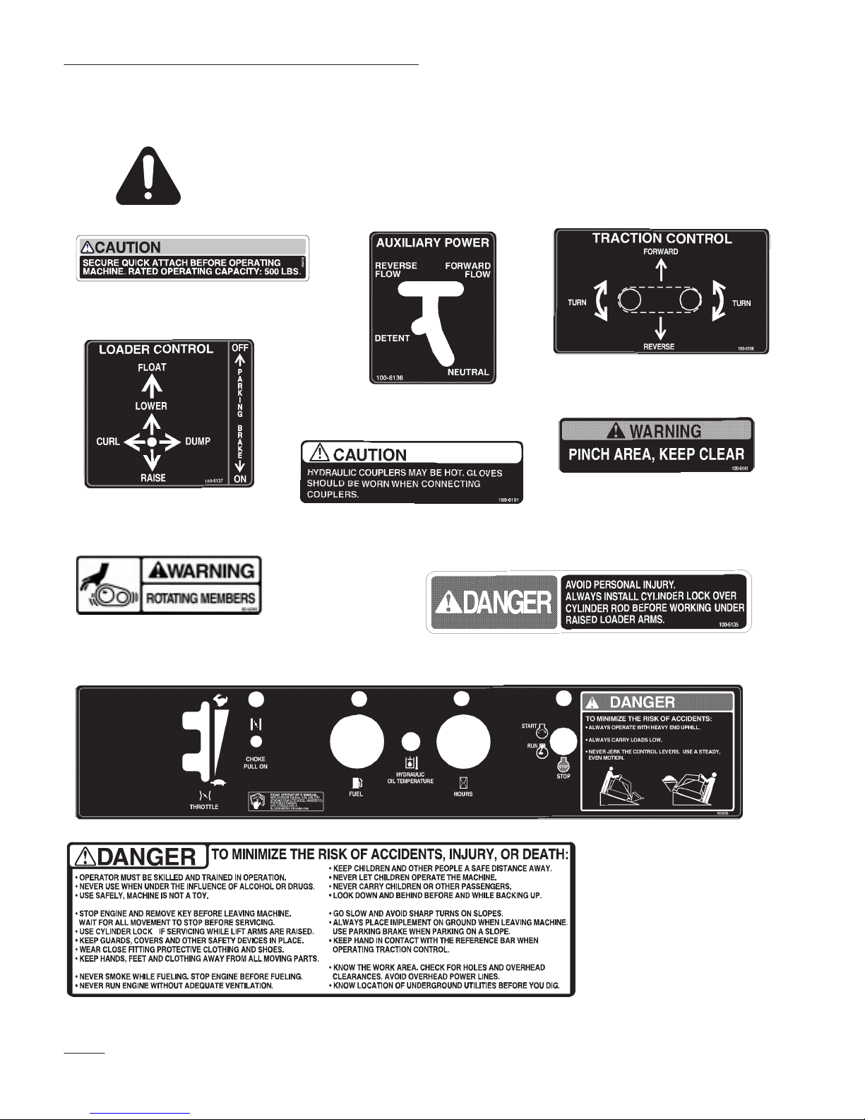
Safety and Instruction Decals
Safety decals and instructions are easily visible to the operator and are located near
any area of potential danger. Replace any decal that is damaged or lost.
On Loader Cross Bar
(Part No. 100–6132)
On Left Control Panel
(Part No. 100–6136)
On Traction Control
(Part No. 100–6138)
On Right Control Panel
(Part No. 100–6137)
On Pump Plate
(Part No. 80–8040)
On Loader Arms by the
Hydraulic Couplers
(Part No. 100–6101)
On Control Panel
(Part No. 100–6139)
Six on Both Sides of
Frame and Loader, and
on top of Loader Arms
(Part No. 100–6141)
On Cylinder Lock
(Part No. 100–6135)
6
On Center Control Panel
(Part No. 100–6140)
Page 9
Assembly
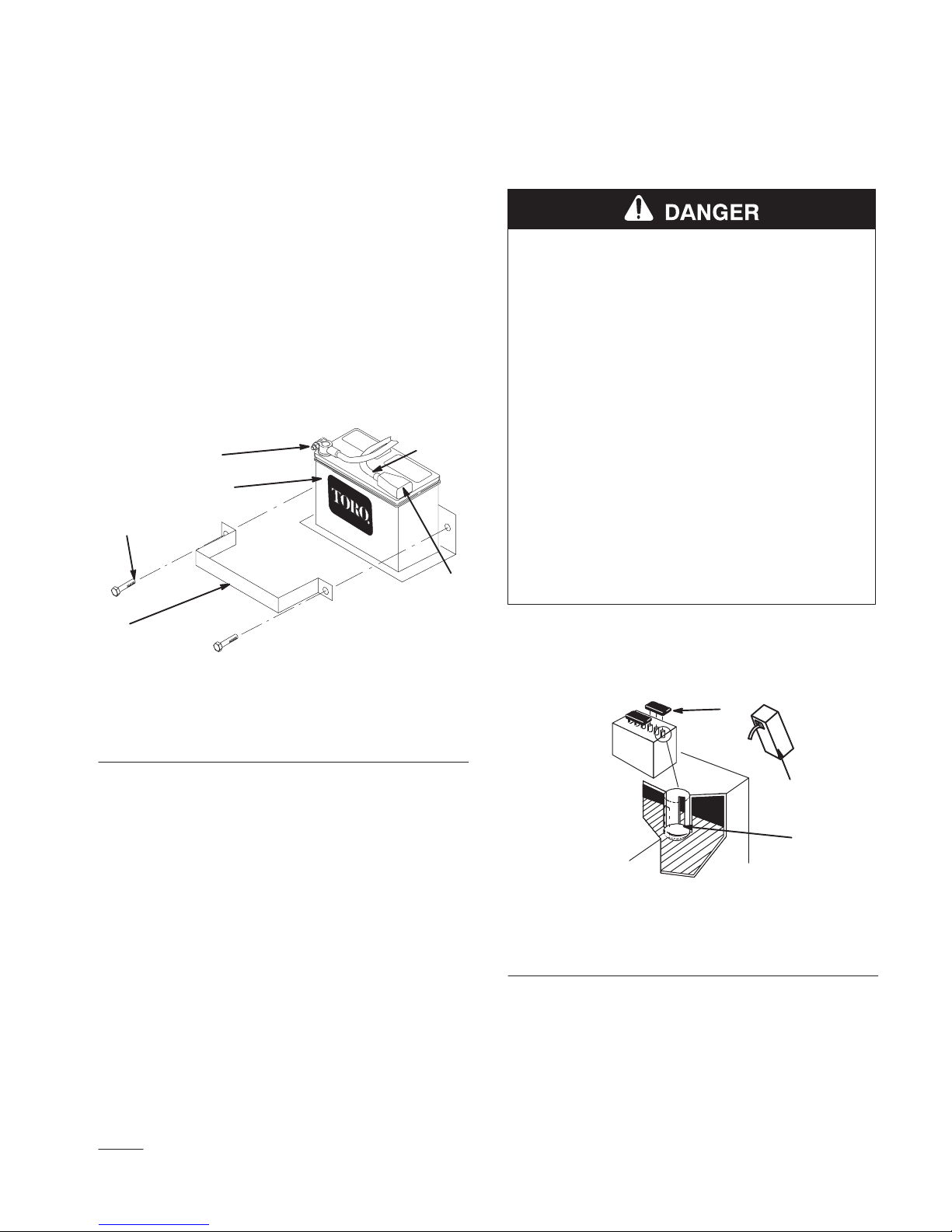
Activating the Battery
The traction unit is shipped with a dry battery.
Purchase bulk electrolyte with 1.260 specific gravity
from a local battery supply outlet.
1. Open the rear access cover; refer to Opening the
Rear Access Cover, page 23.
2. Remove the bolts and clamp securing the battery
(Fig. 1).
3
4
m–4748
6
2
1. Battery
2. Clamp
3. Positive cable
5
1
Figure 1
4. Rubber cover
5. Negative cable
6. Bolts
POTENTIAL HAZARD
• Battery electrolyte contains sulfuric acid
which is a deadly poison and it causes
severe burns.
WHAT CAN HAPPEN
• If you drink electrolyte you could die or if it
gets onto your skin you will be burned.
HOW TO AVOID THE HAZARD
• Do not drink electrolyte and avoid contact
with skin, eyes or clothing. Wear safety
glasses to shield your eyes and rubber
gloves to protect your hands.
• Fill the battery where clean water is always
available for flushing the skin.
• Follow all instructions and comply with all
safety messages on the electrolyte container.
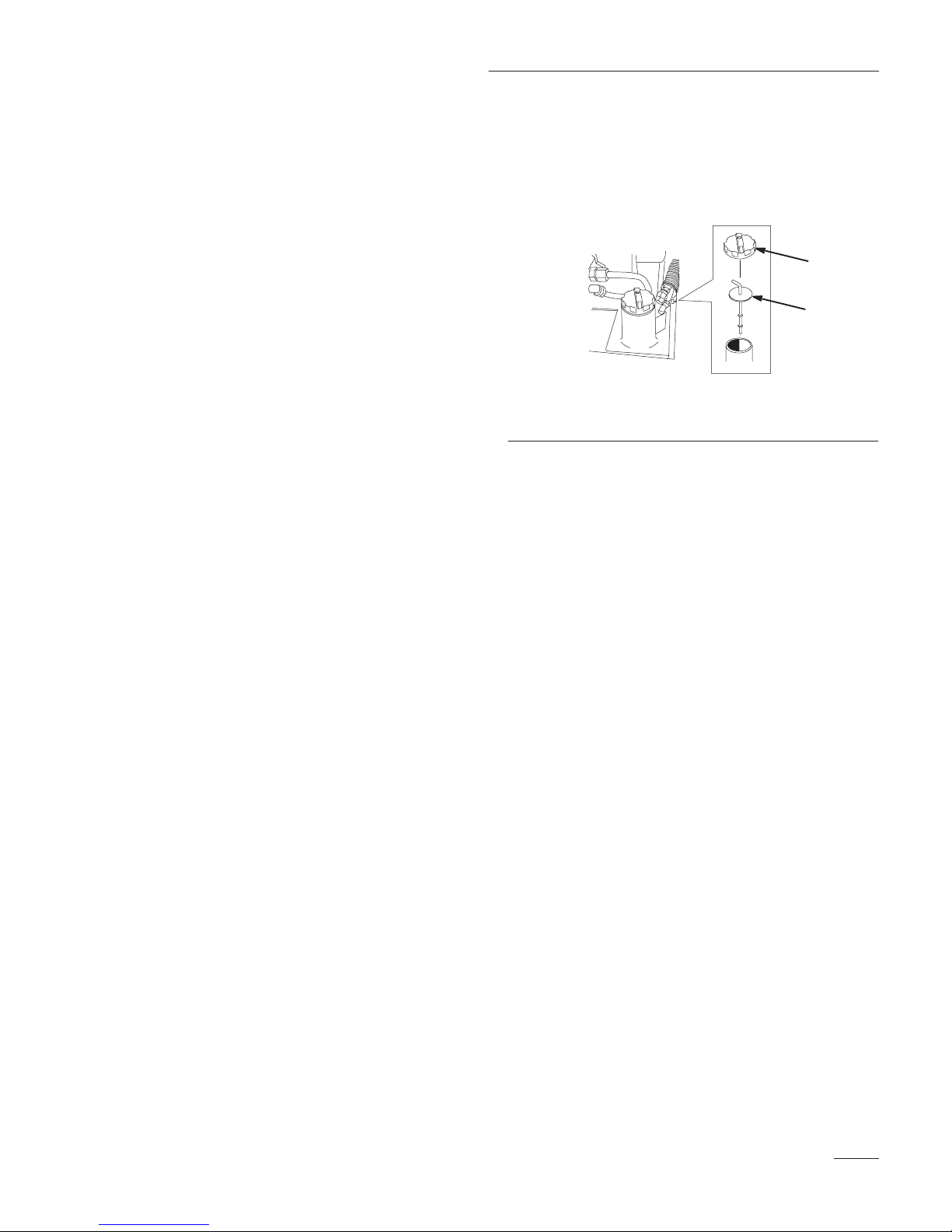
4. Remove filler caps from the battery. Slowly pour
electrolyte into each cell until the electrolyte
level is up to the lower part of the tube (Fig. 2).
1
3. Tilt the top of the battery rearward and slide it
out of the traction unit.
IMPORTANT: Do not allow the battery posts
to touch the frame or hydraulic lines or it
may cause sparks.
7
1. Filler caps
2. Electrolyte
2
3
1262
Figure 2
3. Lower part of the tube
Page 10
Assembly
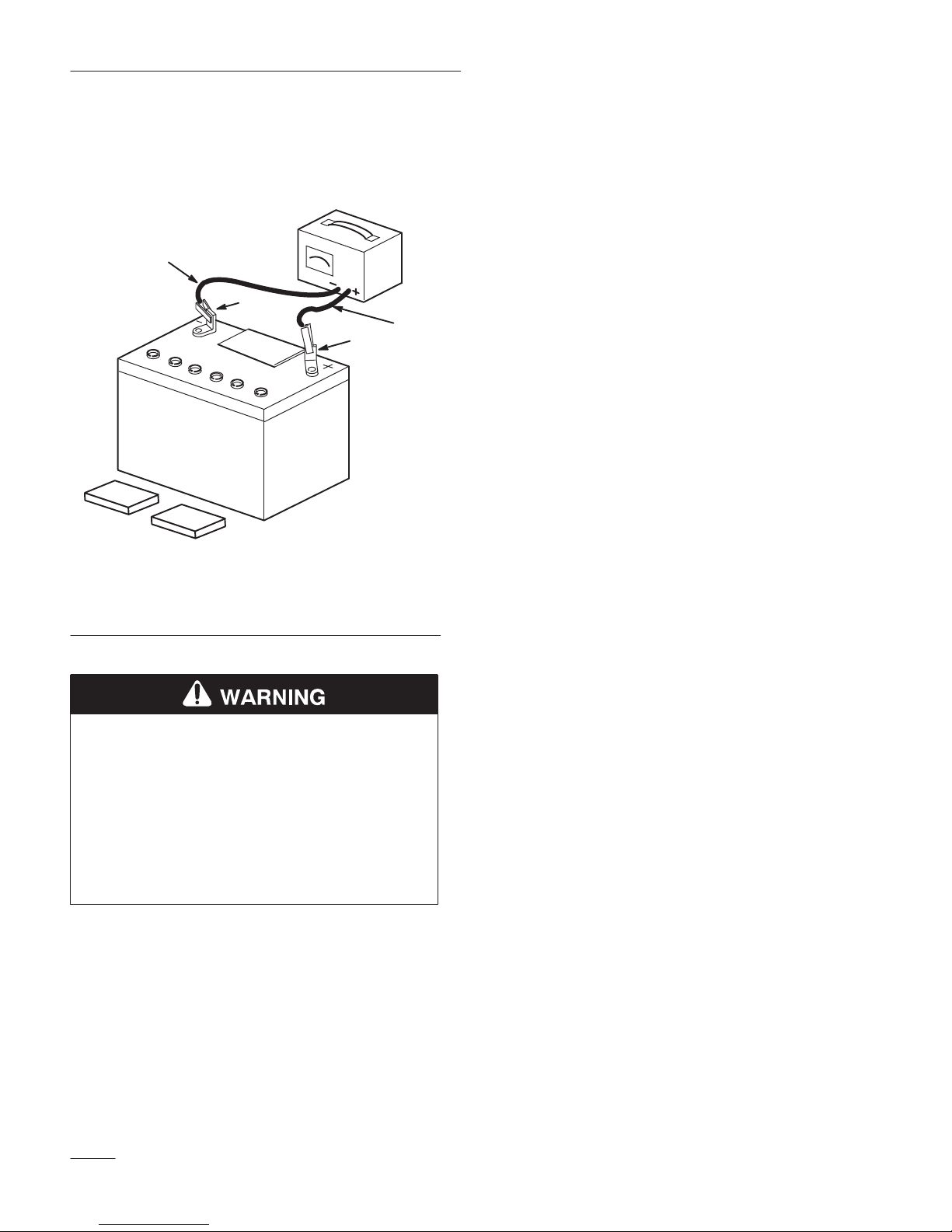
5. Leave the covers off and connect a 3 to 4 amp
battery charger to the battery posts (Fig. 3).
Charge the battery at a rate of 4 amperes or less
for 4 hours (12 volts).
4
2
3
1
Figure 3
1. Positive post
2. Negative post
3. Charger red (+) wire
4. Charger black (–) wire
IMPORTANT: Do not allow the battery posts
to touch the frame or hydraulic lines or it
may cause sparks.
9. Secure the battery in chassis with the clamp and
bolts removed previously (Fig. 1).
10. Using the bolt and nut supplied with the battery,
connect the positive (red) cable to the
positive (+) battery post (Fig. 1). Slide the
rubber cover over the battery post.
11. Using the bolt and nut supplied with the battery,
connect the negative (black) cable to the
negative (–) battery post (Fig. 1).
Note: Ensure that the battery cables do not
contact any sharp edges or each other.
12. Close the rear access cover.
1254
POTENTIAL HAZARD
• Charging the battery produces gasses.
WHAT CAN HAPPEN
• Battery gasses can explode.
HOW TO AVOID THE HAZARD
• Keep cigarettes, sparks, and flames away
from the battery.
6. When the battery is fully charged, disconnect the
charger from the electrical outlet and from the
negative and positive battery posts (Fig. 3).
7. Slowly pour electrolyte into each cell until the
level is once again up to the upper line on the
battery case (Fig. 2) and install covers.
8. Tilt the top of the battery rearward and slide it
into the traction unit.
8
Page 11

Specifications
Overall width 34 in. (86 cm)
Overall length 71 in. (180 cm)
Overall height 43 in. (109 cm)
Weight 1830 lbs (830 kg)
Rated operating capacity 500 lbs (227 kg)
Tipping capacity 1480 lbs (671 kg)
Wheelbase 31.2 in. (79 cm)
Dump height 47 in. (119 cm)
(with narrow bucket)
Reach—fully raised 22 in. (55 cm)
(with narrow bucket)
Height to hinge pin 66 in. (168 cm)
(narow bucket in highest position)
Specifications and design are subject to change
without notice.
Attachments
Many attachments are available for use with the
traction unit. These attachments allow you to to
perform many different functions with the traction
unit such as hauling materials, digging holes, grading,
and more. Contact your Toro dealer for a list of all
approved attachments and accessories.
IMPORTANT: Use only Toro-approved
attachments.
9
Page 12

Check Before Operating
Stability Data
The following table lists the maximum slope recommended for the traction unit in the positions listed in the
table. Slopes over the listed degree may cause the traction unit to become unstable. The data in the table
assumes that the loader arms are fully lowered; raised arms may affect the stability.
Maximum Recommended Slope
when Operating with:
Front Uphill Rear Uphill Side Uphill
Configuration
Traction unit without attachment 11° 21° 19°
Traction unit with an attachment rated with one of the following
stability ratings for each slope position:*
A
B
C
D
E
25° 25° 20°
20° 20° 18°
17° 17° 14°
10° 12° 9°
5° 5° 5°
* In each attachment manual is a set of three stability ratings, one for each hill position. To determine the
maximum slope you can traverse with the attachment installed, find the degree of slope that corresponds to the
stabilities ratings of the attachment.
Example: If the attachment installed on the traction unit has a Front Uphill rating of B, a Rear Uphill rating of
D, and a Side Uphill rating of C, then you could drive forward up a 20
° slope, rearward up a 12° slope, or
sideways on a 14° slope, as listed in the above table.
10
Page 13

Before Operating
Before operating, check the fuel and oil level, and
remove debris from the traction unit. Also, ensure
that the area is clear of people and debris. You should
also know and have marked the locations of all utility
lines.
Adding Fuel
POTENTIAL HAZARD
• When fueling, under certain circumstances,
a static charge can develop, igniting the
gasoline.
WHAT CAN HAPPEN
• A fire or explosion from gasoline can burn
you, others, and cause property damage.
HOW TO AVOID THE HAZARD
• Always place gasoline containers on the
ground away from your vehicle before
filling.
• Do not fill gasoline containers inside a
vehicle or on a truck or trailer bed because
interior carpets or plastic truck bed liners
may insulate the container and slow the
loss of any static charge.
• When practical, remove gas–powered
equipment from the truck or trailer and
refuel the equipment with its wheels on the
ground.
• If this is not possible, then refuel such
equipment on a truck or trailer from a
portable container, rather than from a
gasoline dispenser nozzle.
• If a gasoline dispenser nozzle must be used,
keep the nozzle in contact with the rim of
the fuel tank or container opening at all
times until fueling is complete.
POTENTIAL HAZARD
• In certain conditions gasoline is extremely
flammable and highly explosive.
WHAT CAN HAPPEN
• A fire or explosion from gasoline can burn
you, others, and cause property damage.
HOW TO AVOID THE HAZARD
• Fill the fuel tank outdoors, in an open area,
when the engine is cold. Wipe up any
gasoline that spills.
• Do not fill the fuel tank completely full.
Add gasoline to the fuel tank until the level
is 1/4” to 1/2” (6 mm to 13 mm) below the
bottom of the filler neck. This empty space
in the tank allows gasoline to expand.
• Never smoke when handling gasoline, and
stay away from an open flame or where
gasoline fumes may be ignited by a spark.
• Store gasoline in an approved container
and keep it out of the reach of children.
Never buy more than a 30-day supply of
gasoline.
Use unleaded gasoline (85 pump octane minimum).
Leaded, regular gasoline may be used if unleaded is
not available.
IMPORTANT: Do not use methanol, gasoline
containing methanol, or gasohol containing
more than 10% ethanol because the fuel
system could be damaged. Do not mix oil with
gasoline.
Using Stabilizer/Conditioner
Use a fuel stabilizer/conditioner in the traction unit to
provide the following benefits:
• Keeps gasoline fresh during storage of 90 days
or less. For longer storage it is recommended
that the fuel tank be drained.
11
Page 14

Check Before Operating
• Cleans the engine while it runs
• Eliminates gum-like varnish buildup in the fuel
system, which causes hard starting
IMPORTANT: Do not use fuel additives
containing methanol or ethanol.
Add the correct amount of gas stabilizer/conditioner
to the gas.
Note: A fuel stabilizer/conditioner is most
effective when mixed with fresh
gasoline. To minimize the chance of
varnish deposits in the fuel system, use
fuel stabilizer at all times.
Filling the Fuel Tank
1. Park the traction unit on a level surface, lower
the loader arms, and stop the engine.
2. Remove the key and allow the engine to cool.
3. Clean around the fuel tank cap and remove it.
5. Pull out the dipstick and wipe the metal end
clean (Fig. 4).
6. Slide the dipstick fully into the dipstick tube
(Fig. 4).
4
2
3
m–4745 m–3219
1. Oil dipstick
2. Filler cap
1
Figure 4
3. Valve cover
4. Metal end
7. Pull the dipstick out and look at the metal end.
8. If the oil level is low, clean around the oil filler
cap and remove the cap (Fig. 4).
4. Add unleaded gasoline to the fuel tank, until the
level is just below the bottom of the filler neck.
IMPORTANT: This space in the tank allows
gasoline to expand. Do not fill the fuel tank
completely full.
5. Install the fuel tank cap securely.
6. Wipe up any gasoline that may have spilled.
Checking the Oil Level
1. Park the traction unit on a level surface, lower
the loader arms, and stop the engine.
2. Remove the key and allow the engine to cool.
3. Open the hood; refer to Opening the Hood, page
23.
4. Clean around the oil dipstick (Fig. 4).
9. Slowly pour only enough oil into the valve cover
to raise the level to the F (full) mark.
IMPORTANT: Do not overfill the crankcase
with oil because the engine may be damaged.
10. Replace the filler cap and dipstick.
11. Close the hood.
Removing Debris from the
Traction Unit
IMPORTANT: Operating the engine with
blocked screens, dirty or plugged cooling fins,
and/or cooling shrouds removed, will result in
engine damage from overheating.
1. Park the traction unit on a level surface, lower
the loader arms, and stop the engine.
2. Remove the key and allow the engine to cool.
12
Page 15
Check Before Operating
3. Open the hood; refer to Opening the Hood, page
23.
4. Clean any debris from the front and side screens.
5. Wipe away debris from the air cleaner.
6. Clean any debris build–up on the engine with a
brush or blower.
IMPORTANT: It is preferable to blow dirt
out, rather than washing it out. If water is
used, keep it away from electrical items and
hydraulic valves. Do not use a high-pressure
washer. High–pressure washing can damage
the electrical system and hydraulic valves or
deplete grease.
7. Close the hood.
Checking the Hydraulic Fluid
Check the hydraulic fluid level before the engine is
first started and after every 25 operating hours.
6. Remove the cap from the filler neck and check
the fluid level on the dipstick (Fig. 5).
The fluid level should be between the marks on
the dipstick.
1
2
m–4650
Figure 5
1. Filler neck cap 2. Dipstick
7. If the level is low, add enough fluid to raise it to
the proper level.
8. Install the cap on the filler neck.
9. Close the hood.
Hydraulic Tank Capacity: 6.5 gal. (24.6 l)
Use only Group 1 ISO type 46/68 anti–wear
hydraulic fluids, recommended for ambient
temperatures consistently below 100 F, such as Toro
Hy–Pro, Mobil Fluid 424, or other equivalent fluid.
IMPORTANT: Use only the Group 1 ISO
type 46/68 anti–wear hydraulic fluids. Other
fluids could cause system damage.
1. Remove the attachment, if one is installed; refer
to Removing an Attachment, page 21.
2. Park the traction unit on a level surface, lower
the loader arms, and fully retract the tilt cylinder.
3. Stop the engine, remove the key, and allow the
engine to cool.
4. Open the hood; refer to Opening the Hood, page
23.
5. Clean the area around the filler neck of the
hydraulic tank (Fig. 5).
13
Page 16

Operation
Traction Unit Overview
Figure 6 contains a front and back view of the traction unit. Familiarize yourself with all of the traction unit
components listed in Figure 6.
5
4
3
2
m–4732
1. Track
2. Track adjustment chamber
3. Lift cylinder
4. Cylinder lock
1
6
7
8
9
5. Loader arms
6. Hood
7. Auxiliary hydraulic couplers
8. Tilt cylinder
Figure 6
9. Mount plate
10. Tie-down loop
11. Control panel
10
m–4736
11
13
12. Rear access cover
13. Fuel tank
14. Reverse safety plate
14
12
14
Page 17

Operation
Controls
Become familiar with all the controls (Fig. 7) before
you start the engine and operate the traction unit.
5
6
3
4
m–4663
1. Traction control
2. Loader arm/attachment tilt
lever
3. Auxiliary hydraulics lever
4. Reference bar
5. Throttle lever
6. Choke knob
7
Figure 7
8
9
10
7. Fuel gauge
8. Hydraulic oil temperature
light
9. Hour meter
10. Key switch
11. Parking brake lever
11
Choke Knob
Before starting a cold engine, pull the choke knob
out. After the engine starts, regulate the choke to
keep the engine running smoothly. As soon as
possible, push the choke knob in as far as possible. A
warm engine requires little or no choking.
Reference Bar
When driving the traction unit, use the reference bar
as a handle and a leverage point for controlling the
traction control and the auxiliary hydraulics lever. To
ensure smooth, controlled operation, do not take both
hands off of the reference bar while operating the
21
traction unit.
Traction Control
To move forward, move the traction control forward.
To move rearward, move the traction control rearward
(Fig. 8).
To turn, rotate the traction control in the desired
direction (Fig. 8).
Key Switch
The key switch, used to start and stop the engine, has
three positions: off, run, and start.
To start the engine, rotate the key to the start position.
Release the key when engine starts and it will move
automatically to the run position.
To stop the engine, rotate the key to the off position.
Throttle Lever
Move the control forward to increase the engine
speed and rearward to decrease speed.
The farther you move the traction control in any
direction, the faster the traction unit will move in that
direction.
To stop, release the traction control.
m–4664
Figure 8
Loader Arm/Attachment Tilt Lever
To tilt the attachment forward, slowly move the lever
to the right (Fig. 9).
15
Page 18

Operation
To tilt the attachment rearward, slowly move the lever
to the left (Fig. 9).
To lower the loader arms, slowly move the lever
forward (Fig. 9).
To raise the loader arms, slowly move the lever
rearward (Fig. 9).
You can also push the lever fully forward into a
detent position (Fig. 9) to release the loader arms so
that the attachment rests on the ground. This allows
attachments such as the leveler and the hydraulic
blade to follow the contours of the ground (i.e., float)
when grading.
5
1
43
To operate the auxiliary hydraulics in the reverse
direction using a detent position, rotate the lever
rearward, then move it left into the middle slot
(Fig. 10, Number 4). Only use the detent position for
attachments that require it for operation, such as the
Cement Bowl. To determine if an attachment requires
the detent position, refer to the attachment operator’s
manual.
If you release the lever while in either the forward
position or upper reverse position, the lever will
automatically return to the neutral position
(Fig. 10, Number 1). If it is in the detent position, it
will remain there until you pull it out of the slot.
12
Figure 10
1. Neutral
2. Forward flow hydraulics
3. Reverse flow hydraulics
3
4. Reverse flow
hydraulics—detent
position
4
m–4665
m–4666
1. Lower the loader arms
2. Raise the loader arms
3. Tilt the attachment
rearward
2
Figure 9
4. Tilt the attachment forward
5. Detent (Float) position
By moving the lever to an intermediate position (such
as, forward and left), you can move the loader arms
and tilt the attachment at the same time.
Auxiliary Hydraulics Lever
To operate a hydraulic attachment in the forward
direction, rotate the auxiliary hydraulics lever
rearward and pull it down to the reference bar
(Fig. 10, number 2).
To operate a hydraulic attachment in reverse
direction, rotate the hydraulics lever rearward, then
move it left into the upper slot (Fig. 10, number 3).
Parking Brake Lever
To set the parking brake, pull the brake lever rearward
and then push it to the left, hooking it into the notch
(Fig. 11).
Note: The traction unit may roll slightly
before the brakes engage in the drive
sprocket.
m–4667
Figure 11
16
Page 19

Operation
To release the brake, pull the lever rearward and right,
out of the notch, and then push it forward.
Fuel Gauge
This gauge measures the amount of fuel in the fuel
tank.
Hydraulic Oil Temperature Light
If the hydraulic oil gets too hot, this light illuminates
and an audible alarm sounds. If this happens, stop
the engine and allow the traction unit to cool.
Hour Meter
This meter displays the number of hours that the
traction unit has run since it was built.
Starting and Stopping the
period between attempts. Failure to follow
these instructions can burn out the starter
motor.
5. After the engine starts, gradually push the choke
inward. If the engine stalls or hesitates, pull the
choke out again until the engine warms up.
6. Move the throttle lever to desired setting.
IMPORTANT: If the engine is run at high
speeds when the hydraulic system is cold (i.e.,
when the ambient air temperature is near
freezing or lower), hydraulic system damage
could occur. When starting the engine in cold
conditions, allow the engine to run in the
middle throttle position for 2 to 5 minutes
before moving the throttle to fast (rabbit).
Note: If outdoor temperature is below
freezing, store the traction unit in a
garage to keep it warmer and aid in
starting.
Engine
Starting the Engine
1. Ensure that the auxiliary hydraulics lever is in
neutral.
2. Move the throttle lever midway between slow
(turtle) and fast (rabbit) positions.
3. Pull out the choke lever if you are starting a cold
engine.
Note: A warm or hot engine may not require
choking.
4. Turn the ignition key to the start position. When
the engines starts, release the key.
IMPORTANT: Do not engage the starter for
more than 10 seconds at a time. If the engine
fails to start, allow a 30 second cool-down
Stopping the Engine
1. Move the throttle lever to the slow (turtle)
position.
2. Lower the loader arms to the ground.
3. Turn the ignition key off.
Note: If the engine has been working hard or
is hot, let it idle for a minute before
turning the ignition key off. This helps
cool the engine before it is stopped. In
an emergency, the engine may be
stopped immediately.
17
Page 20

Operation
Stopping the Traction Unit
To stop the traction unit, release the traction control,
move the throttle lever to slow (turtle), lower loader
arms to the ground, and stop the engine. Set the
parking brake and remove the key.
POTENTIAL HAZARD
• Someone could move or attempt to operate
the traction unit while it is unattended.
WHAT CAN HAPPEN
• Children or bystanders may be injured if
they use the traction unit.
HOW TO AVOID THE HAZARD
• Always remove the ignition key when
leaving the traction unit, even if just for a
few seconds.
Moving a Non-functioning
Traction Unit
IMPORTANT: Do not tow or pull the traction
unit without first opening the tow valves, or
the hydraulic system will be damaged
1. Stop the engine.
2. Open the rear access cover; refer to Opening the
Rear Access Cover, page 23.
3. Using a wrench, turn the tow valves on the
hydraulic pumps twice counter-clockwise
(Fig. 12).
2
1
m–4767
Figure 12
1. Left tow valve (right track) 2. Right tow valve (left track)
4. Tow the traction unit as required.
5. When the traction unit has been repaired, close
the tow valves before operating it.
Using the Cylinder Lock
POTENTIAL HAZARD
• The loader arms may lower when in the
raised position.
WHAT CAN HAPPEN
• Anyone under the loader arms may be
injured or crushed.
HOW TO AVOID THE HAZARD
• Always install the cylinder lock when doing
maintenance that requires raised loader
arms.
Installing the Cylinder Lock
18
1. Start the engine.
2. Remove the attachment.
3. Raise the loader arms to the fully raised position.
4. Stop the engine.
Page 21

Operation
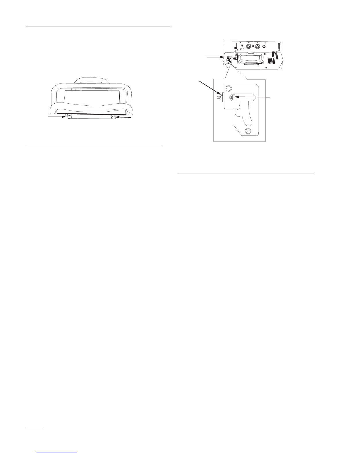
5. Remove the hairpin cotter and clevis pin
securing the cylinder lock to the loader arm
(Fig. 13)
6. Lower the cylinder lock over the cylinder rod
and secure it with the clevis pin and hairpin
cotter (Fig. 13).
1
3
2
1. Cylinder lock
2. Lift cylinder
4
Figure 13
3. Clevis pin
4. Hairpin cotter
m–4672
7. Slowly lower the loader arms until cylinder lock
contacts the cylinder body and rod end.
Removing/Storing the Cylinder Lock
IMPORTANT: Ensure that the cylinder lock
is removed from the rod and fully secured in
the storage position before operating the
traction unit.
1. Start the engine.
2. Raise the loader arms to the fully raised position.
3. Stop the engine.
4. Remove the clevis pin and cotter pin securing
the cylinder lock.
Using Attachments
IMPORTANT: If you are using an attachment
with a serial number of 200999999 or earlier,
the manual for the attachment may contain
information specific to the use of the
attachment with other Dingo models, such as
settings for the flow divider control and speed
selector lever and the use of a counterweight
on the traction unit. These systems are built
into the Dingo TX, and you should ignore any
references to them.
Connecting an Attachment
IMPORTANT: Use only Toro-approved
attachments. Attachments can change the
stability and the operating characteristics of
the traction unit. The warranty of the
traction unit may be voided if used with
unapproved attachments.
IMPORTANT: Before installing the
attachment, ensure that the mount plates are
free of any dirt or debris and that the pins
rotate freely.
1. Position the attachment on a level surface with
enough space behind it to accommodate the
traction unit.
2. Start the engine.
3. Tilt the attachment mount plate forward.
4. Position mount plate into the upper lip of the
attachment receiver plate (Fig. 14).
5. Rotate the cylinder lock up to the loader arm and
secure it with the clevis pin and hairpin cotter
(Fig. 13).
6. Lower the loader arms.
1
2
m–4055
Figure 14
1. Mount plate 2. Receiver plate
19
Page 22

Operation
5. Raise the loader arms while tilting back the
mount plate at the same time.
IMPORTANT: The attachment should be
raised enough to clear the ground, and the
mount plate should be tilted all the way back.
6. Stop the engine.
7. Engage the quick attach pins, ensuring that they
are fully seated in the mount plate (Fig. 15).
2
1
POTENTIAL HAZARD
• If the quick attach pins are not fully seated
through the attachment mount plate, the
attachment could fall off of the traction
unit.
WHAT CAN HAPPEN
• Falling attachments can crush you or
bystanders.
HOW TO AVOID THE HAZARD
• Always ensure that your quick attach pins
are fully seated in the attachment mount
plate.
Connecting the Hydraulic Hoses
If the attachment requires hydraulics for operation,
connect the hydraulic hoses as follows:
1. Stop the engine.
2. Move the auxiliary hydraulics lever forward,
backward, and back to neutral to relieve pressure
at the hydraulic couplers.
3
1. Quick attach pins (shown
in engaged position)
2. Disengaged position
3. Engaged position
Figure 15
4. When engaged, the pin
4
m–4056
must protrude through the
bottom of the attachment
mount plate.
3. Move the auxiliary hydraulics lever into the
detent position.
4. Remove the protective covers from the hydraulic
couplers on the traction unit.
5. Ensure that all foreign matter is cleaned from the
hydraulic connectors.
6. Push the attachment male connector into the
female connector on the traction unit.
Note: When you connect the attachment male
connector first, you will relieve any
pressure build up in the attachment.
20
Page 23

Operation
3. Disengage the quick attach pins by turning them
to the outside.
POTENTIAL HAZARD
• Hydraulic fluid escaping under pressure
can penetrate skin and cause injury.
WHAT CAN HAPPEN
• Fluid accidentally injected into the skin
must be surgically removed within a few
hours by a doctor familiar with this form of
injury or gangrene may result.
HOW TO AVOID THE HAZARD
• Keep body and hands away from pin hole
leaks or nozzles that eject high pressure
hydraulic fluid.
• Use cardboard or paper to find hydraulic
leaks, never use your hands.
POTENTIAL HAZARD
• Hydraulic couplers, hydraulic lines/valves,
and hydraulic fluid may be hot.
4. If the attachment uses hydraulics, move the
auxiliary hydraulics lever forward, back and
forth, and back to neutral to relieve pressure at
the hydraulic couplers.
5. If the attachment uses hydraulics, slide the collar
back on the hydraulic couplers and disconnect
them.
6. Install the protective covers onto the hydraulic
couplers on the traction unit.
7. Start the engine, tilt the mount plate forward,
and back the traction unit away from the
attachment.
Securing the Traction Unit for
Transport
IMPORTANT: Do not operate or drive the
traction unit on roadways.
WHAT CAN HAPPEN
• Contact with hot hydraulic components or
fluid may cause burns.
HOW TO AVOID THE HAZARD
• Wear gloves when operating the hydraulic
couplers.
• Allow the traction unit to cool before
touching hydraulic components.
• Do not touch hydraulic fluid spills.
7. Push the attachment female connector onto the
male connector on the traction unit.
8. Confirm that the connection is secure by pulling
on the hoses.
9. Move the auxiliary hydraulics lever to neutral.
Removing an Attachment
1. Lower the attachment to the ground
IMPORTANT: When transporting the
traction unit on a trailer, always use the
following procedure:
1. Lower the loader arms.
2. Stop the engine.
3. Set the parking brake.
4. Secure the traction unit to the trailer with chains
or straps using the tie-down loops (Fig. 6) to
secure the rear of the traction unit and the loader
arms/mount plate to secure the front of the
traction unit.
2. Stop the engine.
21
Page 24

Maintenance
Service Interval Chart
Each
Service Operation
Engine Oil—check level X
Tracks—inspect X
Check/tighten all fasteners
Chassis—grease
Hydraulic Fluid–check level Initial X
Foam Pre-filter and Paper Air
Filter—clean
Engine Oil—change
Hydraulic lines–check X
Battery–check electrolyte X
Paper Air Filter—replace
Tracks—adjust tension X
Engine Oil Filter–change (every
other oil change)
Spark Plug(s)—check X
Hydraulic Filter–change Initial X
Fuel Filter—replace X
Engine RPM (idle & full
throttle)—check
Hydraulic Fluid–change X
Gasoline—drain
Battery–charge, disconnect
3
cables
Chipped Surfaces—paint
1
More often in dusty, dirty conditions, 2 Immediately after every washing, 3 Storage Service
2
1
1
3
3
1
1
3
Use
X X
Initial X
8 Hours
X
25
Hours
X
Initial X
Hours
100
X
200
Hours
X
400
Hours
Yearly
X
X
X
POTENTIAL HAZARD
• If you leave the key in the ignition switch, someone could start the engine.
WHAT CAN HAPPEN
• Accidental starting of the engine could seriously injure you or other bystanders.
HOW TO AVOID THE HAZARD
• Remove the key from the ignition switch and and disconnect negative battery cable
from battery before you do any maintenance.
22
Page 25

Accessing the Engine and
Internal Components
Before opening any of the covers, stop the engine and
remove the key.
Opening the Hood
Maintenance
1. Pull out the hood latch in the front screen
(Fig. 16).
2. Swing the hood up until it locks open (Fig. 16).
1
2
m–4737
Figure 16
1. Hood 2. Hood latch
1
m–4771
Figure 17
1. Bar
2. Secure the hood by pushing down on the front of
the hood until it locks in place.
Opening the Rear Access Cover
1. Pull out and forward on the latch to remove it
from the locking bracket on the traction unit
frame (Fig. 18).
2. Swing the rear access cover to the right
(Fig. 18).
Closing the Hood
1. Pull up on the bar securing the hood in the open
position and lower the hood (Fig. 17).
m–4670
Figure 18
23
Page 26

Maintenance
Closing the Rear Access Cover
1. Swing the rear access cover to the left and seat it
in place over the back of the traction unit.
2. Place the latch over the locking bracket
(Fig. 18).
3. Pull the latch rearward and push it in to lock it in
place (Fig. 18).
Removing a Side Screen
1. Open the hood.
2. Pull out and turn the two locking tabs on the
inside of the side screen until they line up with
the slots in the screen (Fig. 19).
1
4. Turn the tabs and fold them down to lock the
screen in place (Fig. 19).
Removing the Front Screen
1. Open the hood and remove both side screens.
2. Remove the four bolts securing the front screen
to the traction unit frame and remove the front
screen (Fig. 20).
1
2
m–4740
1
1. Side screen 2. Locking tab
2
m–4738
Figure 19
3. Slide the screen inward, off of the tabs and pull
it up and out of the engine compartment.
Installing a Side Screen
1. Slide the screen into the engine compartment
and line up the holes in the bottom of the screen
with the rubber posts in the traction unit frame.
2. Push the screen firmly down over the rubber
posts.
3. Slide the slots in the screen over the locking tabs
(Fig. 19).
Figure 20
1. Front screen 2. Bolts (left side bolt not
shown)
3. When finished, install the front screen inside the
loader arms with the four bolts removed
previously.
Adjusting the Controls
The factory adjusts the controls before shipping the
traction unit. However, after many hours of use, you
may need to adjust the neutral position of the traction
control, the tracking of the traction control in the full
forward position, and the reverse flow stop of the
auxiliary hydraulics lever.
Adjusting the Traction Control Neutral
Position
If the traction unit creeps forward or backward when
the traction control is in neutral and the unit is warm,
immediately complete the following procedure:
24
Page 27

1. Park the traction unit on a flat surface and lower
the loader arms.
Maintenance
2. Stop the engine and remove the key.
3. Lift/support the traction unit so that both tracks
are off of the ground.
POTENTIAL HAZARD
• The traction unit could become unstable
and fall.
WHAT CAN HAPPEN
• You or bystanders could be crushed.
HOW TO AVOID THE HAZARD
• Ensure that you support the traction unit
so that it is stable and cannot fall.
4. Open the rear access cover; refer to Opening the
Rear Access Cover, page 23.
5. Loosen the jam nuts on the traction rods, under
the control panel (Fig. 21).
POTENTIAL HAZARD
• When the traction unit is running, parts
are moving and the engine gets hot.
WHAT CAN HAPPEN
• You could be caught in moving parts and
injured or burned on hot surfaces.
HOW TO AVOID THE HAZARD
• Take extra care to stay away from pinch
points, moving parts, and hot surfaces
when adjusting the running traction unit.
7. If the left track moves, lengthen or shorten the
right traction rod until the track stops moving.
8. If the right track moves, lengthen or shorten the
left traction rod until the track stops moving.
9. Tighten the jam nuts.
10. Close the rear access cover.
11. Stop the engine and lower the traction unit to the
ground.
1 1
2
Figure 21
1. Traction rod 2. Jam nut
2
m–4770
6. Start the traction unit and set the throttle to about
1/3 open position.
Adjusting the Tracking of the Traction
Control, Full Forward Position
If the traction unit does not drive straight when you
hold the traction control against the reference bar,
complete the following procedure:
1. Drive the traction unit with the traction control
against the reference bar, noting which direction
the traction unit veers.
2. Release the traction control.
3. If the traction unit veers to the left, loosen the
the right jam nut and adjust the tracking set
screw on the front of the traction control
(Fig. 22).
25
Page 28
Maintenance
4. If the traction unit veers to the right, loosen the
the left jam nut and adjust the tracking set screw
on the front of the traction control
(Fig. 22).
1
m–4664
1
Figure 22
1. Jam nut and set screw
1
5. Repeat steps 1 through 4 until the traction unit
drives straight in the full forward position.
Adjusting the Auxiliary Hydraulics Lever,
Reverse Flow Stop
In the reverse flow slot of the auxiliary hydraulics
lever assembly is a bolt that keeps the lever from
going too far into the slot into a detent position (i.e., a
position that allows it to stay in the slot without being
held by the operator). If the lever goes into a detent
position, or if the reverse flow hydraulics speed is
slow, adjust the bolt using the following procedure:
2
3
m–4777
Figure 23
1. Left control panel cover
2. Jam nut
3. Adjustment bolt
4. Turn the adjustment bolt clockwise until the
lever slips into a detent position.
5. Slowly turn the adjustment bolt
counter-clockwise until the lever slips out of a
detent position.
6. Hold the adjustment bolt and tighten the jam nut.
7. Install the left panel cover.
1. Stop the engine and remove the key.
2. Remove the three bolts securing the left control
panel cover and remove the cover (Fig. 23).
3. Loosen the jam nut on the adjustment bolt
(Fig. 23).
Servicing the Air Cleaner
Foam Pre-filter: Clean every 25 operating hours.
Paper Filter: Clean every 25 operating hours.
Replace after every 100 operating hours.
Note: Service the air cleaner more frequently
if operating conditions are extremely
dusty or sandy.
Removing the Foam and Paper Filters
1. Lower the loader arms, stop the engine, and
remove the key.
26
Page 29
Maintenance
2. Open the hood; refer to Opening the Hood,
page 23.
3. Clean around the air cleaner to prevent dirt from
getting into the engine and causing damage.
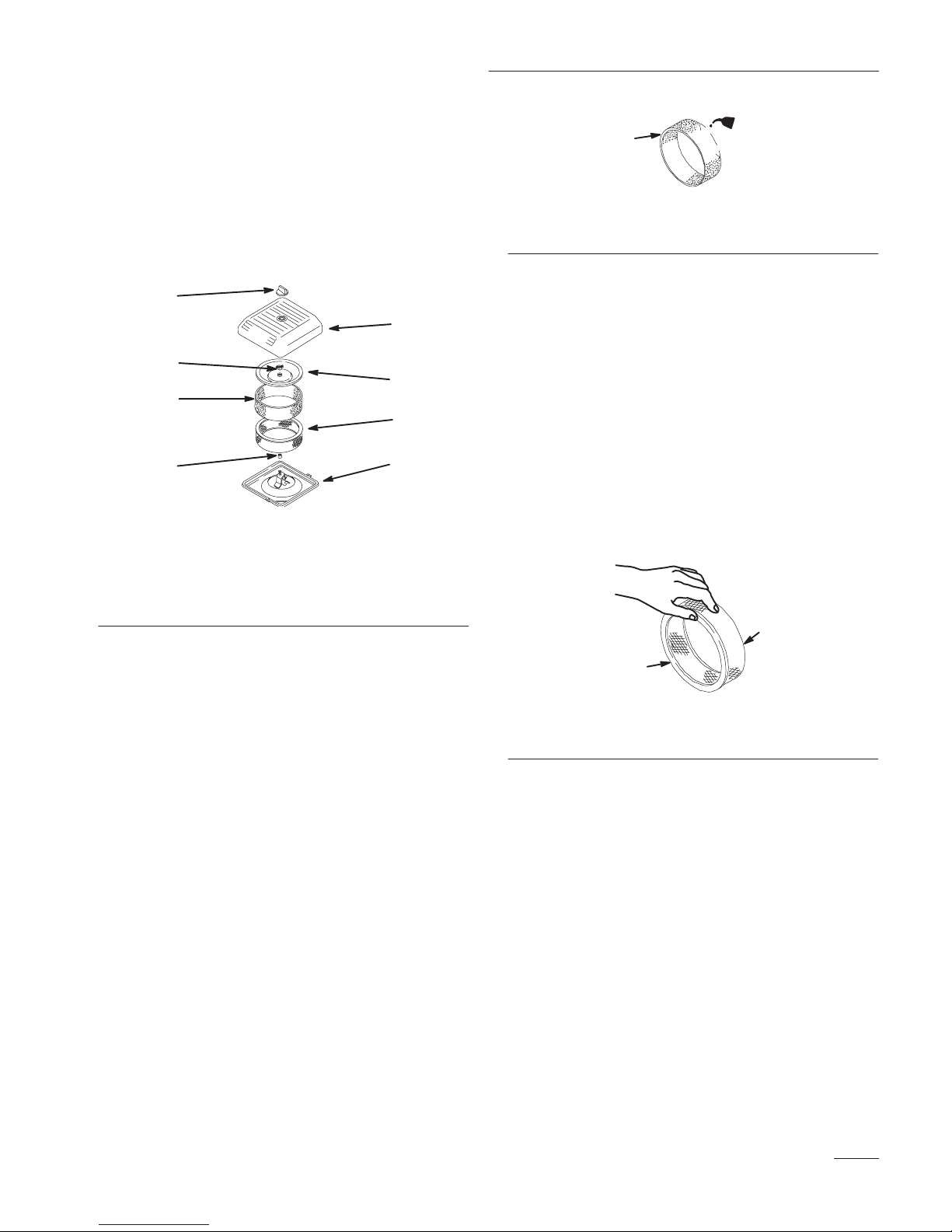
4. Unscrew the knob and remove the air cleaner
cover (Fig. 24).
1
2
3
4
5
6
87
m–4653
Figure 24
1. Knob
2. Air cleaner cover
3. Cover nut
4. Cover
5. Foam pre-filter
6. Paper filter
7. Rubber seal
8. Air cleaner base
2
1
m–1213
Figure 25
1. Foam element 2 . Oil
4. Squeeze the pre-filter to distribute the oil.
5. Lightly tap the paper filter on a flat surface to
remove dust and dirt (Fig. 26).
6. Inspect the paper filter for tears, an oily film, and
damage to the rubber seal.
IMPORTANT: Never clean the paper element
with pressurized air or liquids, such as
solvent, gas, or kerosene. Replace the paper
element if it is damaged, or cannot be cleaned
thoroughly (i.e., after approximately 100
operating hours).
5. Carefully slide the foam pre-filter off of the
paper element (Fig. 24).
6. Unscrew the cover nut and remove the cover and
paper filter (Fig. 24).
Cleaning the Filters
IMPORTANT: Replace the foam element if it
is torn or worn.
1. Wash the foam pre-filter in liquid soap and warm
water. When clean, rinse it thoroughly.
2. Dry the pre-filter by squeezing it in a clean cloth
(do not wring).
3. Put one or two ounces of oil on the pre-filter
(Fig. 25).
1
2
m–1213
Figure 26
1. Paper element 2. Rubber seal
Installing the Filters
IMPORTANT: To prevent engine damage,
always operate the engine with the complete
foam and paper air cleaner assembly
installed.
1. Carefully slide the foam pre-filter onto the paper
filter (Fig. 24).
2. Place the air cleaner assembly onto the air
cleaner base (Fig. 24).
3. Install the cover and secure it with the wingnut
(Fig. 24).
27
Page 30

Maintenance
4. Install the air cleaner cover and secure with the
knob (Fig. 24).
5. Close the hood.
Servicing the Engine Oil
Change oil after the first 25 operating hours and then
every 100 operating hours thereafter.
Note: Change oil more frequently when
operating conditions are extremely
dusty or sandy.
Oil Type: Detergent oil (API service SG or SH)
Crankcase Capacity: w/filter, 2.1 qt. (2 l)
Viscosity: See table below
USE THESE SAE VISCOSITY OILS
10W–30, 10W–40
5W–20, 5W–30
–20 0 20
°
F
–30°–20 –10
C
40 60
32
01020
80 100
30 40
POTENTIAL HAZARD
• Components will be hot if the traction unit
has been running.
WHAT CAN HAPPEN
• Touching hot components can cause burns.
HOW TO AVOID THE HAZARD
• Allow the traction unit to cool before
performing maintenance or any touching
components.
4. Remove the drain plug (Fig. 27).
1
m–4751
Figure 27
1. Oil drain valve
5. When the oil has drained completely, replace the
plug.
Changing the Oil
1. Start the engine and let it run for five minutes.
This warms the oil so it drains better.
2. Park the traction unit so that the drain side is
slightly lower than the opposite side to ensure
that the oil drains completely.
3. Lower the loader arms, set the parking brake,
stop the engine, and remove the key.
28
Note: Dispose of the used oil at a certified
recycling center.
6. Remove the oil fill cap and slowly pour
approximately 80% of the specified amount of
oil in through the valve cover.
7. Check the oil level; refer to Checking the Oil
Level, page 12.
8. Slowly add additional oil to bring the level to the
F (full) mark on the dipstick.
9. Replace the fill cap.
Page 31
Maintenance
Changing the Oil Filter
Replace the oil filter every 200 hours or every other
oil change.
Note: Change the oil filter more frequently
when operating conditions are
extremely hot, dusty, or sandy.
1. Drain the oil from the engine; refer to Changing
the Oil, page 28.
2. Place a shallow pan or rag under the filter to
catch oil.
3. Remove the old filter (Fig. 28) and wipe the
surface of the filter adapter gasket.
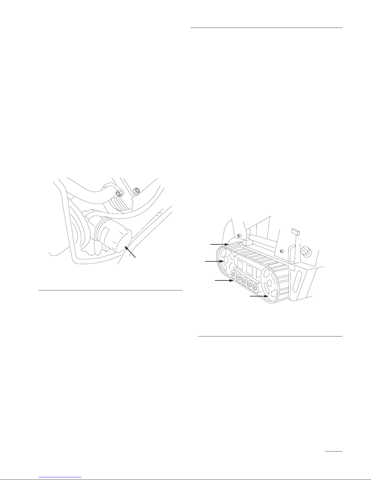
Servicing the Tracks
Check the tracks for excessive wear and clean them
periodically. If the tracks are worn, replace them.
Cleaning the Tracks
1. With a bucket on the loader arms, lower the
bucket to the ground so that the front of the
traction unit lifts off of the ground a few inches.
2. Stop the engine, and remove the key.
3. Using a water hose or pressure washer, remove
dirt from each track system.
IMPORTANT: Ensure that you fully clean
the road wheels, the tension wheel, and the
drive sprocket (Fig. 29). The road wheels
should rotate freely when clean.
1
Figure 28
1. Oil filter
m–1256
4. Pour new oil of the proper type through the
center hole of the filter. Stop pouring when the
oil reaches the bottom of the threads.
5. Allow a minute or two for the oil to be absorbed
by filter material, then pour off the excess oil.
6. Apply a thin coat of new oil to the rubber gasket
on the replacement filter.
7. Install the replacement oil filter to the filter
adapter. Turn the oil filter clockwise until the
rubber gasket contacts the filter adapter, then
tighten the filter an additional 1/2 turn.
8. Fill the crankcase with the proper type of new
oil; refer to Changing the Oil, page 28.
1
2
3
1. Track
2. Tension wheel
4
Figure 29
3. Road wheels
4. Drive Sprocket
m–4736
Replacing the Tracks
When the tracks are badly worn, replace them.
1. Lower the loader arms, stop the engine, and
remove the key.
2. Lift/support the side of the unit to be worked on
so that the track is three to four inches (7.6 to 10
cm.) off of the ground.
29
Page 32

Maintenance
3. Remove the locking bolt and nut (Fig. 30).
4
1. Locking bolt
2. Tensioning screw
23
1
Figure 30
m–4747
3. Fork tube
4. Tension wheel
4. Using a 1/2 in. drive socket, release the drive
tension by turning the tensioning screw
clockwise (Fig. 30 and 31).
5. Push the tension wheel toward the rear of the
unit to move the fork tube against the frame
(Fig. 31). (If it does not touch the frame,
continue turning the tensioning screw until it
does.)
1
3
4
8
5
m–4774
2
Figure 31
1. Track
2. 1/2 in. socket
3. Tension wheel
4. Fork tube
5. Track lug
6. Drive sprocket
7. Sprocket spacer
8. Road wheels
9. Push the track under and between the road
wheels (Fig. 31).
10. Starting at the bottom of the tension wheel,
install the track around the wheel by rotating the
track rearward while pushing the lugs into the
wheel.
7
6
6. Begin removing the track at the top of the
tension wheel, peeling it off of the wheel while
rotating the track forwards.
7. When the track is off of the tension wheel,
remove it from the drive sprocket and road
wheels (Fig. 31).
8. Beginning at the drive sprocket, coil the new
track around the sprocket, ensuring that the lugs
on the track fit between the spacers on the
sprocket (Fig. 31).
11. Turn the tensioning screw counter-clockwise
until the distance between the tension nut and
the back of the fork tube (Fig. 32) is 2 3/4 in.
(7 cm.).
30
Page 33

Maintenance
m–4775
1
Figure 32
1. 2 3/4 in. (7 cm)
12. Align the closest notch in the tension screw to
the locking bolt hole and secure the screw with
the locking bolt and nut.
13. Lower the traction unit to the ground.
Removing the Spark Plugs
1. Lower the loader arms, stop the engine, and
remove the key.
2. Open the hood; refer to Opening the Hood,
page 23.
3. Pull the wires off of the spark plugs (Fig. 33).
4. Clean around the spark plugs.
5. Remove both spark plugs and metal washers.
1
2
m–3876
14. Repeat steps 2 through 13 to replace the other
track.
Servicing the Spark Plugs
Check the spark plugs after every 200 operating
hours. Ensure that the air gap between the center and
side electrodes is correct before installing each spark
plug. Use a spark plug wrench for removing and
installing the spark plugs and a gapping tool/feeler
gauge to check and adjust the air gap. Install new
spark plugs if necessary.
Type: Champion RC12YC (or equivalent) Air Gap:
0.030 in. (0.76 mm)
Figure 33
1. Spark plug wire 2. Spark plug
Checking the Spark Plugs
1. Look at the center of both spark plugs (Fig. 34).
If you see light brown or gray on the insulator,
the engine is operating properly. A black coating
on the insulator usually means the air cleaner is
dirty.
IMPORTANT: Never clean the spark plugs.
Always replace the spark plugs when they
have a black coating, worn electrodes, an oily
film, or cracks.
2. Check the gap between the center and side
electrodes (Fig. 34).
31
Page 34

Maintenance
3. Bend the side electrode (Fig. 34) if the gap is not
correct.
2
1
1. Center electrode insulator
2. Side electrode
Figure 34
3. Air gap (not to scale)
3
0.030 in .
(0.76 mm)
m–3215
Installing the Spark Plugs
1. Thread the spark plugs into the spark plug holes.
2. Tighten the spark plugs to 20 ft-lb (27 N.m).
3. Push the wires onto the spark plugs (Fig. 33).
4. Close the hood.
m–4732
Figure 35
m–4056
Figure 36
4. Pump grease into the fittings until grease begins
to ooze out of the bearings (approximately 3
pumps).
Greasing the Traction Unit
Grease all pivot joints every 8 operating hours and
immediately after every washing.
Grease Type: General-purpose grease.
1. Lower the loader arms and stop the engine.
Remove the key.
2. Clean the grease fittings with a rag.
3. Connect a grease gun to each fitting
(Fig 35 and 36).
5. Wipe up any excess grease.
Changing the Fuel Filter
Change the fuel filter after every 200 operating hours
or yearly, whichever occurs first.
Never re–install a dirty filter.
1. Lower the loader arms, stop the engine, and
remove the key.
2. Open the hood and remove the left side screen;
refer to Accessing the Engine and Internal
Components, page 23.
3. Loosen the tank cap to relieve pressure.
32
Page 35

Maintenance
4. Clamp the fuel lines on both sides of the fuel
filter (Fig. 37).
5. Squeeze the ends of the hose clamps together
and slide them away from the filter (Fig. 37).
1
2
Figure 37
1. Filter 2. Hose clamp
6. Place a drain pan under the fuel lines to catch
any leaks, then remove the filter from the fuel
lines.
m–3217
Draining the Fuel Tank
POTENTIAL HAZARD
• In certain conditions gasoline is extremely
flammable and highly explosive.
WHAT CAN HAPPEN
• A fire or explosion from gasoline can burn
you, others, and cause property damage.
HOW TO AVOID THE HAZARD
• Drain gasoline from the fuel tanks when the
engine is cold. Do this outdoors in an open
area. Wipe up any gasoline that spills.
• Do not drain gasoline near an open flame
or where gasoline fumes may be ignited by
a spark.
• Do not smoke while handling fuel.
• Do not syphon the fuel by mouth; instead,
use a pump type or mechanical syphon.
7. Loosen the screw securing the fuel filter clamp
and slide the filter free of the clamp.
8. Install a new filter in the clamp and tighten the
clamp screw to secure it.
9. Slide the fuel line back on the fuel filter fittings
and move the hose clamps close to the filter.
10. Remove the clamp blocking fuel flow and open
the fuel valves.
11. Secure the tank cap.
12. Replace the side screen and close the hood.
1. Lower the loader arms, stop the engine, and
remove the key.
2. Syphon the gasoline from the tank using a pump
type syphon.
Note: Now is the best time to install a new
fuel filter because the fuel tanks are
empty.
Servicing the Hydraulic
System
Replacing the Hydraulic Filter
Change the hydraulic filter:
• After the first 8 operating hours.
• After every 200 operating hours.
1. Position traction unit on a level surface.
33
Page 36

Maintenance
2. Lower the loader arms, stop the engine, and
remove the key.
3. Open the hood, refer to Opening the Hood, page
23.
IMPORTANT: Do not substitute an
automotive oil filter or severe hydraulic
system damage may result.
4. Place a drain pan under the filter (Fig. 38).
Note: You may need to remove the front
screen in order to catch the oil; refer to
Removing the Front Screen, page 24.
5. Remove the old filter (Fig. 38) and wipe the
surface of the filter adapter gasket clean.
6. Apply a thin coat hydraulic fluid to the rubber
gasket on the replacement filter.
7. Install the replacement hydraulic filter onto the
filter adapter (Fig. 38). Tighten it clockwise until
the rubber gasket contacts the filter adapter, then
tighten the filter an additional 3/4 turn.
POTENTIAL HAZARD
• Hydraulic fluid escaping under pressure
can penetrate skin and cause injury.
WHAT CAN HAPPEN
• Fluid accidentally injected into the skin
must be surgically removed within a few
hours by a doctor familiar with this form of
injury or gangrene may result.
HOW TO AVOID THE HAZARD
• Keep body and hands away from pin hole
leaks or nozzles that eject high pressure
hydraulic fluid.
• Use cardboard or paper to find hydraulic
leaks, never use your hands.
11. Check the fluid level in the hydraulic tank (refer
to Checking the Hydraulic Fluid, page 13) and
add fluid to raise the level to mark on dipstick.
Do not over fill the tank.
12. Close the hood.
1
Figure 38
1. Hydraulic filter
8. Clean up any spilled fluid.
9. Start the engine and let it run for about two
minutes to purge air from the system.
10. Stop the engine and check for leaks.
m–4651
Changing the Hydraulic Fluid
Change the hydraulic fluid after every 400 operating
hours or yearly.
1. Position the traction unit on a level surface.
2. Open the hood, refer to Opening the Hood, page
23.
3. Remove the front screen, refer to Removing the
Front Screen, page 24.
4. Lower the loader arms, retract the tilt cylinder,
stop the engine, and remove the key.
5. Allow the traction unit it cool completely.
IMPORTANT: Do not substitute automotive
oil or severe hydraulic system damage may
result.
34
Page 37

Maintenance
6. Remove the Hydraulic tank cap and dipstick
(Fig. 39).
7. Remove the top cover of the hydraulic tank and
discard the gasket under the cover (Fig. 39).
1
3
4
5
1. Hydraulic tank cap
2. Dipstick
3. Top cover
Figure 39
4. Gasket
5. Hydraulic tank
2
m–4772
8. Using a pump type or mechanical syphon,
syphon the oil out of the tank.
11. Fill the hydraulic tank with approximately 6 gal.
(22.7 l) of Toro Hy-Pro, Mobil Fluid 424, or
equivalent (refer to Checking Hydraulic Fluid,
page 13).
Note: Dispose of used oil at a certified
recycling center.
12. Start the engine and let it run for a few minutes.
13. Stop the engine.
14. Check the hydraulic fluid level and top it off if
necessary (refer to Checking Hydraulic Fluid on
page 13).
15. Close the hood.
Checking Hydraulic Lines
After every 100 operating hours, check the hydraulic
lines and hoses for leaks, loose fittings, kinked lines,
loose mounting supports, wear, weather, and chemical
deterioration. Replace all moving hydraulic hoses
every 1500 hours or 2 years, which ever comes first.
Make necessary repairs before operating.
POTENTIAL HAZARD
• Hydraulic oil is poisonous.
WHAT CAN HAPPEN
• If you syphon the oil by mouth, you may
ingest the oil or petroleum fumes, resulting
in severe illness or death.
HOW TO AVOID THE HAZARD
• Do not syphon the oil by mouth, instead use
a pump type or mechanical syphon.
9. Clean the inside of the tank and the outlet screen
with a clean, dry cloth.
10. Install the tank cover with a new gasket
(available from your Toro Dealer), and torque
the cover bolts to 25 in-lbs (2.8 N⋅m).
POTENTIAL HAZARD
• Hydraulic fluid escaping under pressure
can penetrate skin and cause injury.
WHAT CAN HAPPEN
• Fluid accidentally injected into the skin
must be surgically removed within a few
hours by a doctor familiar with this form of
injury or gangrene may result.
HOW TO AVOID THE HAZARD
• Keep body and hands away from pin hole
leaks or nozzles that eject high pressure
hydraulic fluid.
• Use cardboard or paper to find hydraulic
leaks, never use your hands.
35
Page 38

Maintenance
Servicing the Battery
Check the electrolyte level in the battery every 100
hours. Always keep the battery clean and fully
charged. Use a paper towel to clean the battery case.
If the battery terminals are corroded, clean them with
a solution of four parts water and one part baking
soda. Apply a light coating of grease to the battery
terminals to reduce corrosion.
Voltage: 12 v, 380 Cold Cranking Amps
Checking the Electrolyte Level
1. Open covers to see into the cells. The electrolyte
must be up to the lower part of the tube
(Fig. 40).
IMPORTANT: Do not allow the electrolyte to
get below the plates. (Fig. 40).
1
2
1. Filler caps
2. Lower part of tube
Figure 40
3. Plates
3
1262
3. Slowly pour distilled water into each battery cell
until the level is up to the lower part of the tube
(Fig. 40).
IMPORTANT: Do not overfill the battery
because electrolyte (sulfuric acid) can cause
severe corrosion and damage to the chassis.
4. Press the filler caps onto the battery.
Charging the Battery
IMPORTANT: Always keep the battery fully
charged (1.260 specific gravity). This is
especially important to prevent battery
damage when the temperature is below 32°F
(0°C).
1. Check the electrolyte level; refer to Checking
Electrolyte Level, page 36.
2. Remove the filler caps from the battery and
connect a 3 to 4 amp battery charger to the
battery posts. Charge the battery at a rate of 4
amperes or less for 4 hours (12 volts). Do not
overcharge the battery.
3. Install the filler caps after the battery is fully
charged.
2. If the electrolyte is low, add the required amount
of distilled water; refer to Adding Water to the
Battery, below.
Adding Water to the Battery
The best time to add distilled water to the battery is
just before you operate the traction unit. This lets the
water mix thoroughly with the electrolyte solution.
1. Clean the top of the battery with a paper towel.
2. Lift off the filler caps (Fig. 40).
36
POTENTIAL HAZARD
• Charging the battery produces gasses.
WHAT CAN HAPPEN
• Battery gasses can explode.
HOW TO AVOID THE HAZARD
• Keep cigarettes, sparks, and flames away
from the battery.
Cleaning the Chassis
Over time, the chassis under the engine collects dirt
and debris that must be removed. Using a flashlight,
open the hood and inspect the area under the engine
Page 39

Maintenance
on a regular basis. When the debris is one to two
inches deep, complete the following procedure (refer
to Figure 41 throughout this procedure):
1
3
1. Side weights
2. Rear panel
3. Fuel tank bracket
5
4
2
1
m–4773
Figure 41
4. Fuel tank
5. Chassis
11. Disconnect the fuel line.
12. Disconnect the two wires leading to the right
side of the tank (Fig. 42).
2
1
m–4776
Figure 42
1. Black wire 2. Orange wire
13. Carefully remove the tank and set it upright to
keep from spilling the gasoline.
1. Lift and support the front of the traction unit.
2. Stop the engine and remove the key.
3. Disconnect the negative battery cable.
4. Remove the bolts, washers, and lock washers
securing the two side weights, removing the
weights (Fig. 41).
5. Open the rear access cover; refer to Opening the
Rear Access Cover, page 23.
6. Remove the three carriage bolts and washers
from the battery base and the fuel tank bracket,
removing the bracket (Fig. 41).
7. Remove the six nuts and bolts securing the rear
panel, removing the panel (Fig. 41).
8. Loosen the tank cap to relieve pressure.
9. Place a clamp on the fuel line, two inches from
where it comes out of the fuel tank.
10. Slide the fuel tank to the rear (Fig. 41).
POTENTIAL HAZARD
• In certain conditions gasoline is extremely
flammable and highly explosive.
WHAT CAN HAPPEN
• A fire or explosion from gasoline can burn
you, others, and cause property damage.
HOW TO AVOID THE HAZARD
• Remove the fuel tank outdoors in an open
area. Wipe up any gasoline that spills.
• Do not remove the fuel tank near an open
flame or where gasoline fumes may be
ignited by a spark.
• Do not smoke while handling fuel tank.
14. Remove any large deposits of debris.
15. Wash out the chassis with water until the water
running out the back of the unit is clear.
IMPORTANT: Take care not to get water into
the engine or electrical components.
16. Slide the fuel tank part way into the chassis
(Fig. 41).
37
Page 40

Maintenance
17. Connect the fuel line and remove the clamp.
18. Secure the tank cap.
19. On the right side of the tank, connect the orange
wire to the center post and the black wire to the
outside post (Fig. 42).
20. Slide the tank all the way into the traction unit.
IMPORTANT: The fuel line and wires must
be away from the engine pulleys and the
frame.
21. Replace the rear panel and secure it with the six
bolts and nuts removed previously (Fig. 41).
22. Place the fuel tank bracket over the tank and
secure it and the battery tray with the bolts and
washers removed previously (Fig. 41).
23. Install the side weights with the bolts, washers,
and lock washers removed previously (Fig. 41).
5. Change the crankcase oil; refer to Servicing the
Engine Oil, page 28.
6. Remove the spark plugs and check the condition
of each; refer to Servicing the Spark Plugs,
page 31.
7. With the spark plugs removed from the engine,
pour two tablespoons of engine oil into each
spark plug hole.
8. Place rags over the spark plug holes to catch any
oil spray, then use the starter to crank the engine
and distribute the oil inside the cylinder.
9. Install the spark plugs, but do not install the
wires on the spark plugs.
10. Charge the battery; refer to Servicing the Battery,
page 36.
11. For storage over 30 days, prepare the traction
unit as follows.
24. Close the rear access cover.
25. Lower the traction unit to the ground.
Storage
1. Lower the loader arms, stop the engine, and
remove the key.
2. Remove dirt and grime from the external parts of
the entire traction unit, especially the engine.
Clean dirt and chaff from the outside of the
engine’s cylinder head fins and blower housing.
IMPORTANT: You can wash the traction unit
with mild detergent and water. Do not
pressure wash the traction unit. Avoid
excessive use of water, especially near the
control panel, engine, hydraulic pumps, and
motors.
3. Service the air cleaner; refer to Servicing the Air
Cleaner, page 26.
4. Grease the traction unit; refer to Greasing the
Traction Unit, page 32.
A. Add a petroleum based
stabilizer/conditioner to fuel in the tank.
Follow mixing instructions from stabilizer
manufacturer. (1 oz. per gallon). Do not use
an alcohol based stabilizer (ethanol or
methanol).
Note: A fuel stabilizer/conditioner is most
effective when mixed with fresh
gasoline and used at all times.
B. Run the engine to distribute conditioned
fuel through the fuel system (5 minutes).
C. Stop the engine, allow it to cool and drain
the fuel tank using a pump type syphon.
D. Restart the engine and run it until it stops.
E. Choke the engine.
F. Start and run the engine until it will not
start again.
G. Dispose of fuel properly. Recycle as per
local codes.
38
Page 41

IMPORTANT: Do not store
stabilizer/conditioned gasoline over 90 days.
12. Check and tighten all bolts, nuts, and screws.
Repair or replace any part that is damaged or
defective.
13. Paint all scratched or bare metal surfaces. Paint
is available from your Authorized Service
Dealer.
14. Store the traction unit in a clean, dry garage or
storage area. Remove the key from the ignition
switch and keep it in a memorable place.
15. Cover the traction unit to protect it and keep it
clean.
Maintenance
39
Page 42

Troubleshooting
g,,
g
g
PROBLEM POSSIBLE CAUSES CORRECTIVE ACTION
Starter does not crank 1. Battery is dead. 1. Charge the battery.
Engine will not start, starts hard, or
fails to keep running.
Engine loses power.
2. Electrical connections are
corroded or loose.
3. Relay or switch is defective. 3. Contact Authorized Service
1. Fuel tank is empty. 1. Fill fuel tank with gasoline.
2. Choke is not on. 2. Move choke lever fully
3. Air cleaner is dirty. 3. Clean or replace air cleaner
4. Spark plug wires are loose or
disconnected.
5. Spark plugs are pitted, fouled,
or gap is incorrect.
6. Dirt in fuel filter. 6. Replace fuel filter.
7. Dirt, water, or stale fuel is in
fuel system.
1. Engine load is excessive. 1. Reduce ground speed.
2. Air cleaner is dirty. 2. Clean air cleaner element.
3. Oil level in crankcase is low. 3. Add oil to crankcase.
2. Check electrical connections
for good contact.
Dealer.
forward.
element.
4. Install wires on spark plugs.
5. Install new, correctly gapped
spark plugs.
7. Contact Authorized Service
Dealer.
Engine overheats.
40
4. Cooling fins and air passages
under engine blower housing
are plugged.
5. Spark plugs are pitted, fouled,
or gap is incorrect.
6. Dirt in fuel filter. 6. Replace fuel filter.
7. Dirt, water, or stale fuel is in
fuel system.
1. Engine load is excessive. 1. Reduce ground speed.
2. Oil level in crankcase is low. 2. Add oil to crankcase.
3. Cooling fins and air passages
under engine blower housing
are plugged.
4. Remove obstruction from
cooling fins and air passages.
5. Install new, correctly gapped
spark plugs.
7. Contact Authorized Service
Dealer.
3. Remove obstruction from
cooling fins and air passages.
Page 43

PROBLEM CORRECTIVE ACTIONPOSSIBLE CAUSES
Troubleshooting
Abnormal vibration. 1. Engine mounting bolts are
loose.
Traction unit does not drive. 1. The parking brake is on.
2. Hydraulic fluid level low.
3. The tow valves are open.
4. Hydraulic system is
damaged.
1. Tighten engine mounting
bolts.
1. Release the parking brake.
2. Add hydraulic fluid.
3. Close the tow valves
4. Contact your Toro dealer.
41
Page 44

The Toro Dingo Product Line Warranty
A One-Year Limited Warranty
Conditions and Products Covered
The Toro Company and its affiliate, Toro Warranty Company, pursuant to an agreement between them, jointly warrant your Toro
Dingo Product (“Product”) to be free from defects in materials or
workmanship for one year or 500 operational hours, whichever occurs first. Where a warrantable condition exists, we will repair the
Product at no cost to you including diagnosis, labor, and parts. This
warranty begins on the date the Product is delivered to the original
retail purchaser.
Instructions for Obtaining Warranty Service
Should you feel your Toro Product contains a defect in materials or
workmanship, contact the distributor or dealer who sold you the
product or any Authorized Dingo Service Dealer. The Yellow
Pages of your telephone directory is a good reference source. The
dealer will arrange service at his/her dealership. You may need
proof of purchase (copy of registration card, sales receipt, etc.) for
warranty validation.
If for any reason you are dissatisfied with the Service Dealer’s analysis of the defect in materials or workmanship or if you need a referral to a Toro Dingo Service Dealer, please feel free to contact us at :
LCB Customer Service Department
Toro Warranty Company
8111 Lyndale Avenue South
Bloomington, MN 55420-1196
612-888-8801
888-577-7466
Owner Responsibilities
You must maintain your Toro Product by following the maintenance
procedures described in the operator’s manual. Such routine
maintenance, whether performed by a dealer or by you, is at your
expense. Parts scheduled for replacement as required maintenance (“Maintenance Parts”), are warranted for the period of time
up to the scheduled replacement time for that part. Failure to perform required maintenance and adjustments can be grounds for
disallowing a warranty claim.
Items and Conditions Not Covered
Not all product failures or malfunctions that occur during the warranty period are defects in materials or workmanship. This express
warranty does not cover:
• Product failures which result from the use of non-Toro replacement parts, or from installation and use of add-on,
modified, or unapproved accessories.
• Product failures which result from failure to perform required
maintenance and/or adjustments.
• Product failures which result from operating the Product in
an abusive, negligent or reckless manner.
• Parts subject to consumption through use unless found to be
defective. Examples of parts which are consumed, or used
up, during normal Product operation include, but are not limited to, digging teeth, tines, spark plugs, tires, filters, chains,
etc.
• Failures caused by outside influence. Items considered to be
outside influence include, but are not limited to, weather,
storage practices, contamination, use of unapproved coolants, lubricants, additives, or chemicals, etc.
• Normal “wear and tear” items. Normal “wear and tear” includes, but is not limited to, worn painted surfaces,
scratched decals or windows, etc.
• Any component covered by a separate manufacturer’s warranty.
• Pickup and delivery charges.
General Conditions
Repair by an Authorized Toro Service Dealer is your sole remedy
under this warranty.
Neither The Toro Company nor Toro Warranty Company is liable
for indirect, incidental or consequential damages in connection
with the use of the Toro Products covered by this warranty, including any cost or expense of providing substitute equipment or service during reasonable periods of malfunction or non-use pending
completion of repairs under this warranty. Some states do not allow
exclusions of incidental or consequential damages, or limitations
on how long an implied warranty lasts, so the above exclusions
and limitations may not apply to you.
This warranty gives you specific legal rights, and you may also
have other rights which vary from state to state.
Except for the Emissions warranty referenced below, if applicable,
there is no other express warranty. All implied warranties of merchantability and fitness for use are limited to the duration of this ex press warranty.
Note to California residents: The Emissions Control System on
your Product may be covered by a separate warranty meeting requirements established by the U.S. Environmental Protection
Agency (EPA) or the California Air Resources Board (CARB). The
hour limitations set forth above do not apply to the Emissions Control System Warranty. Refer to the California Emission Control
Warranty Statement printed in you operator’s manual or contained
in the engine manufacturer’s documentation for details.
Countries Other than the United States or Canada
Customers who have purchased Toro products exported from the United States or Canada should contact their Toro Distributor (Dealer)
to obtain guarantee policies for your country, province, or state. If for any reason you are dissatisfied with your Distributor’s service or
have difficulty obtaining guarantee information, contact the Toro importer. If all other remedies fail, you may contact us at Toro Warranty
Company.
Rev. 11/17/1999
 Loading...