

Page 1
FormNo.3403-166RevA
Dingo
ModelNo.22317—SerialNo.314000001andUp
®
220CompactToolCarrier
Registeratwww.T oro.com.
OriginalInstructions(EN)
*3403-166*A
Page 2
WARNING
CALIFORNIA
Proposition65Warning
Thisproductcontainsachemicalorchemicals
knowntotheStateofCaliforniatocausecancer,
birthdefects,orreproductiveharm.
Theengineexhaustfromthisproduct
containschemicalsknowntotheStateof
Californiatocausecancer,birthdefects,
orotherreproductiveharm.
Becauseinsomeareastherearelocal,state,orfederal
regulationsrequiringthatasparkarresterbeusedonthe
engineofthismachine,asparkarresterisavailableas
anoption.Ifyourequireasparkarrester,contactyour
AuthorizedToroServiceDealer.
CustomerServiceandhavethemodelandserialnumbersof
yourproductready.Figure1identiesthelocationofthe
modelandserialnumbersontheproduct.Writethenumbers
inthespaceprovided.
GenuineT orosparkarrestersareapprovedbytheUSDA
ForestryService.
Important:ItisaviolationofCaliforniaPublic
ResourceCodeSection4442touseoroperatetheengine
onanyforest-covered,brush-covered,orgrass-covered
landwithoutasparkarrestermufermaintainedin
workingorder,ortheengineconstricted,equipped,and
maintainedforthepreventionofre.Otherstatesor
federalareasmayhavesimilarlaws.
ThissparkignitionsystemcomplieswithCanadianICES-002.
Theenclosed
Engine Owner's Man ual
issuppliedfor
informationregardingtheUSEnvironmentalProtection
Agency(EPA)andtheCaliforniaEmissionControl
Regulationofemissionsystems,maintenance,and
warranty.Replacementsmaybeorderedthroughthe
enginemanufacturer.
Introduction
Thismachineisacompacttoolcarrierintendedforusein
variousearthandmaterialsmovingactivitiesforlandscaping
andconstructionwork.Itisdesignedtooperateawidevariety
ofattachmentseachofwhichperformaspecializedfunction.
Figure1
1.Modelandserialnumberlocation
ModelNo.
SerialNo.
Thismanualidentiespotentialhazardsandhassafety
messagesidentiedbythesafetyalertsymbol(Figure2),
whichsignalsahazardthatmaycauseseriousinjuryordeath
ifyoudonotfollowtherecommendedprecautions.
Figure2
1.Safetyalertsymbol
Thismanualuses2otherwordstohighlightinformation.
Importantcallsattentiontospecialmechanicalinformation
andNoteemphasizesgeneralinformationworthyofspecial
attention.
Readthisinformationcarefullytolearnhowtooperateand
maintainyourproductproperlyandtoavoidinjuryand
productdamage.Youareresponsibleforoperatingthe
productproperlyandsafely.
YoumaycontactTorodirectlyatwww .Toro.comforproduct
andaccessoryinformation,helpndingadealer,ortoregister
yourproduct.
Wheneveryouneedservice,genuineT oroparts,oradditional
information,contactanAuthorizedServiceDealerorToro
©2016—TheToro®Company
8111LyndaleAvenueSouth
Bloomington,MN55420
Contactusatwww.Toro.com.
2
PrintedintheUSA.
AllRightsReserved
Page 3

Contents
Safety
Safety...........................................................................3
SafeOperatingPractices...........................................3
SlopeIndicator.......................................................6
SafetyandInstructionalDecals.................................7
Setup............................................................................9
1InstallingtheValveLever.......................................9
2CheckingFluidLevelsandDriveChain
Tension..............................................................9
3ChargingtheBattery..............................................9
ProductOverview.........................................................11
Controls...............................................................11
Specications........................................................13
Attachments/Accessories........................................13
StabilityData.........................................................14
Operation....................................................................15
AddingFuel...........................................................15
CheckingtheEngineOilLevel.................................16
RemovingDebrisfromtheTractionUnit...................16
CheckingtheHydraulicFluidLevel...........................17
CheckingtheTirePressure......................................17
StartingandStoppingtheEngine..............................17
DrivingtheTractionUnit........................................18
StoppingtheTractionUnit......................................18
MovingaNon-functioningTractionUnit...................18
UsingtheCylinderLocks.........................................18
UsingAttachments.................................................19
SecuringtheTractionUnitforTransport....................20
AdjustingtheThighSupport....................................20
Maintenance.................................................................22
RecommendedMaintenanceSchedule(s)......................22
Lubrication...............................................................23
GreasingtheTractionUnit......................................23
EngineMaintenance..................................................23
ServicingtheAirCleaner.........................................23
ServicingtheCarbonCanister..................................24
ServicingtheEngineOil..........................................25
ServicingtheSparkPlugs.........................................26
FuelSystemMaintenance...........................................27
ChangingtheFuelFilter..........................................27
DrainingtheFuelTank...........................................27
ElectricalSystemMaintenance....................................28
ReplacingtheBattery..............................................28
ServicingtheBattery...............................................29
DriveSystemMaintenance.........................................30
ServicingtheTractionDriveChains..........................30
HydraulicSystemMaintenance....................................32
ReplacingtheHydraulicFilter..................................32
ChangingtheHydraulicFluid...................................32
CheckingtheHydraulicLines...................................33
Storage........................................................................33
Troubleshooting...........................................................35
Schematics...................................................................36
Improperuseormaintenancebytheoperatororowner
canresultininjury.T oreducethepotentialforinjury,
complywiththesesafetyinstructionsandalways
payattentiontothesafetyalertsymbol
means:
instruction.Failuretocomplywiththeinstructionmay
resultinpersonalinjuryordeath.
Caution
,
W ar ning
,or
Danger
,which
—personalsafety
SafeOperatingPractices
Thisproductiscapableofamputatinghandsandfeet.Always
followallsafetyinstructionstoavoidseriousinjuryordeath.
WARNING
Engineexhaustcontainscarbonmonoxide,an
odorless,deadlypoisonthatcankillyou.
Donotruntheengineindoorsorinanenclosed
area.
Training
•ReadtheOperator'sManualandothertrainingmaterial.If
theoperator(s)ormechanic(s)cannotreadEnglish,itis
theowner'sresponsibilitytoexplainthismaterialtothem.
•Becomefamiliarwiththesafeoperationoftheequipment,
operatorcontrols,andsafetysigns.
•Alloperatorsandmechanicsshouldbetrained.The
ownerisresponsiblefortrainingtheusers.
•Neverletchildrenoruntrainedpeopleoperateorservice
theequipment.Localregulationsmayrestricttheageof
theoperator.
•Theowner/usercanpreventandisresponsiblefor
accidentsorinjuriesoccurringtohimselforherself,other
peopleorproperty.
Preparation
•Evaluatetheterraintodeterminewhataccessoriesand
attachmentsareneededtoproperlyandsafelyperform
thejob.Onlyuseaccessoriesandattachmentsapproved
bythemanufacturer.
•Wearappropriateclothingincludingeyeprotection,
slip-resistantsubstantialfootwear,andhearingprotection.
Tiebacklonghair.Donotwearjewelry.
•Beforedigging,havetheareamarkedforunderground
utilities,anddonotdiginmarkedareas.
•Beforeoperatinginanareawithhigh-voltagelinesor
cables,contacta“One-CallSystemDirectory”service.In
theUSA,call811oryourlocalutilitycompany.Ifyou
donotknowyourlocalutilitycompany’sphonenumber,
callthenationalnumber(USAandCanadaonly)at
1-888-258-0808.Also,contactanyutilitycompaniesthat
arenotparticipantsofthe“One-CallSystemDirectory”
service.
3
Page 4

•Inspecttheareawheretheequipmentistobeusedand
removeallobjectssuchasrocks,toys,andwirewhichcan
bethrownbythemachine.
•Useextracarewhenhandlinggasolineandotherfuels.
Theyareammableandvaporsareexplosive.
–Useonlyanapprovedcontainer
–Neverremovethegascaporaddfuelwiththeengine
running.Allowtheenginetocoolbeforerefueling.
Donotsmoke.
–Neverrefuelordrainthemachineindoors.
•Checkthattheoperator'spresencecontrols,safety
switches,andshieldsareattachedandfunctioning
properly.Donotoperateunlesstheyarefunctioning
properly.
Operation
•Neverrunanengineinanenclosedarea.
•Onlyoperateingoodlight,keepingawayfromholesand
hiddenhazards.
•Besurealldrivesareinneutralbeforestartingtheengine.
Onlystarttheenginefromtheoperator'sposition.
•Slowdownanduseextracareonhillsides.Besureto
travelintherecommendeddirectiononhillsides.Turf
conditionscanaffectthemachine'sstability.
•Slowdownandusecautionwhenmakingturns,crossing
roadsandsidewalks,andwhenchangingdirectionson
slopes.
•Neveroperatewiththeguardsnotsecurelyinplace.Be
sureallinterlocksareattached,adjustedproperly ,and
functioningproperty.
•Donotchangetheenginegovernorsettingoroverspeed
theengine.
•Stoponlevelground,lowerimplements,disengagethe
auxiliaryhydraulics,andshutofftheenginebeforeleaving
theoperator'spositionforanyreason.
•Keephandsandfeetawayfrommovingattachments.
•Lookbehindanddownbeforebackinguptobesureof
aclearpath.
•Nevercarrypassengersandkeeppetsandbystanders
away.
•Donotoperatethemachinewhiletired,ill,orunderthe
inuenceofalcoholordrugs.
•Usecarewhenloadingorunloadingthemachineintoa
trailerortruck.
•Usecarewhenapproachingblindcorners,shrubs,trees,
orotherobjectsthatmayobscurevision.
•Readallattachmentmanuals.
•Ensurethattheareaisclearofotherpeoplebefore
operatingthetractionunit.Stopthetractionunitif
anyoneentersthearea.
•Neverleavearunningtractionunitunattended.Always
lowertheloaderarms,stoptheengine,andremovethe
keybeforeleaving.
•Donotexceedtheratedoperatingcapacity,asthetraction
unitmaybecomeunstablewhichmayresultinlossof
control.
•Donotcarryaloadwiththearmsraised.Alwayscarry
loadsclosetotheground.
•Donotover-loadtheattachmentandalwayskeepthe
loadlevelwhenraisingtheloaderarms.Logs,boards,and
otheritemscouldrolldowntheloaderarms,injuringyou.
•Neverjerkthecontrols;useasteadymotion.
•Watchfortrafcwhenoperatingnearorcrossing
roadways.
•Donottouchpartswhichmaybehotfromoperation.
Allowthemtocoolbeforeattemptingtomaintain,adjust,
orservice.
•Checkforoverheadclearances(i.e.branches,doorways,
electricalwires)beforedrivingunderanyobjectsanddo
notcontactthem.
•Ensurethatyouoperatethetractionunitinareaswhere
therearenoobstaclesincloseproximitytotheoperator.
Failuretomaintainadequatedistancefromtrees,walls,
andotherbarriersmayresultininjuryasthetractionunit
backsupduringoperationiftheoperatorisnotattentive
tothesurroundings.Onlyoperatetheunitinareaswhere
thereissufcientclearancefortheoperatortosafely
maneuvertheproduct.
•Locatethepinchpointareasmarkedonthetractionunit
andattachmentsandkeephandsandfeetawayfrom
theseareas.
•Beforeoperatingthetractionunitwithanattachment,
ensurethattheattachmentisproperlyinstalled.
•Donotplaceyourfeetundertheplatform.
•Lightningcancausesevereinjuryordeath.Iflightning
isseenorthunderisheardinthearea,donotoperate
themachine;seekshelter.
SlopeOperation
Slopesareamajorfactorrelatedtoloss-of-controland
tip-overaccidents,whichcanresultinsevereinjuryordeath.
Allslopesrequireextracaution.
•Donotoperatethetractionunitonhillsidesorslopes
exceedingtheanglesrecommendedinStabilityData
(page14),andthoseintheattachmentOperator'sManual.
SeealsotheSlopeIndicator(page6).
•Operateupanddownslopeswiththeheavyendof
thetractionunituphill.W eightdistributionchanges.
Anemptybucketwillmaketherearofthetractionunit
theheavyend,andafullbucketwillmakethefrontofthe
tractionunittheheavyend.Mostotherattachmentswill
makethefrontoftractionunittheheavyend.
•Raisingtheloaderarmsonaslopewillaffectthestability
ofthemachine.Wheneverpossible,keeptheloaderarms
intheloweredpositionwhenonslopes.
•Removinganattachmentonaslopewillmaketherear
ofthetractionunitheavy.RefertoStabilityData(page
4
Page 5

14),todeterminewhethertheattachmentcanbesafely
removedontheslope.
connectingordisconnectingitfromthebattery.Wear
protectiveclothinganduseinsulatedtools.
•Removeobstaclessuchasrocks,treelimbs,etc.fromthe
workarea.Watchforholes,ruts,orbumps,asuneven
terraincouldoverturnthetractionunit.Tallgrasscan
hideobstacles.
•UseonlyToro-approvedattachments.Attachmentscan
changethestabilityandtheoperatingcharacteristicsof
thetractionunit.Warrantymaybevoidedifusedwith
unapprovedattachments.
•Keepallmovementsonslopesslowandgradual.Donot
makesuddenchangesinspeedordirection.
•Avoidstartingorstoppingonaslope.Ifthetractionunit
losestraction,proceedslowly,straightdowntheslope.
•Avoidturningonslopes.Ifyoumustturn,turnslowly
andkeeptheheavyendofthetractionunituphill.
•Donotoperateneardrop-offs,ditches,orembankments.
Thetractionunitcouldsuddenlyturnoverifawheelgoes
overtheedgeofaclifforditch,orifanedgecavesin.
•Donotoperateonwetgrass.Reducedtractioncould
causesliding.
•Donotparkthetractionunitonahillsideorslope
withoutloweringtheattachmenttothegroundand
chockingthewheels.
•Keepallpartsingoodworkingconditionandallhardware
tightened.Replaceallwornordamageddecals.
•Ifanymaintenanceorrepairrequirestheloaderarmsto
beintheraisedposition,securethearmsintheraised
positionwiththehydrauliccylinderlock.
•Keepnutsandboltstight.Keepequipmentingood
condition.
•Nevertamperwithsafetydevices.
•Keepthetractionunitfreeofgrass,leaves,orotherdebris
build-up.Cleanupoilorfuelspillage.Allowthetraction
unittocoolbeforestoring.
•Useextracarewhenhandlinggasolineandotherfuels.
Theyareammableandvaporsareexplosive.
–Useonlyanapprovedcontainer.
–Neverremovethegascaporaddfuelwhenthe
engineisrunning.Allowtheenginetocoolbefore
refueling.Donotsmoke.
–Neverrefuelthetractionunitindoors.
–Neverstorethetractionunitorfuelcontainerinside
wherethereisanopename,suchasnearawater
heaterorfurnace.
•Donottrytostabilizethetractionunitbyputtingyour
footontheground.
MaintenanceandStorage
•Disengagetheauxiliaryhydraulics,lowertheattachment,
stoptheengine,andremovethekey.Waitforall
movementtostopbeforeadjusting,cleaning,orrepairing.
•Cleandebrisfromattachments,drives,mufers,and
enginetohelppreventres.Cleanupoilorfuelspillage.
•Lettheenginecoolbeforestoringanddonotstorenear
ame.
•Donotstorefuelnearamesordrainindoors.
•Parkthemachineonlevelground.Neverallowuntrained
personneltoservicethemachine.
•Usejackstandstosupportcomponentswhenrequired.
•Carefullyreleasepressurefromcomponentswithstored
energy.
•Disconnectthebatteryorremovethesparkplugwires
beforemakinganyrepairs.Disconnectthenegative
terminalrstandthepositivelast.Reconnectpositive
rstandnegativelast.
–Neverllacontainerwhileitisinsideavehicle,trunk,
pick-upbed,oranysurfaceotherthantheground.
–Keepcontainernozzleincontactwiththetankduring
lling.
•Stopandinspecttheequipmentifyoustrikeanobject.
Makeanynecessaryrepairsbeforerestarting.
•UseonlygenuineTororeplacementpartstoensurethat
originalstandardsaremaintained.
•Batteryacidispoisonousandcancauseburns.Avoid
contactwithskin,eyes,andclothing.Protectyourface,
eyes,andclothingwhenworkingwithabattery.
•Batterygasescanexplode.Keepcigarettes,sparksand
amesawayfromthebattery.
•Keepyourbodyandhandsawayfrompinholeleaks
ornozzlesthatejecthighpressurehydraulicuid.Use
cardboardorpapertondhydraulicleaks;neveruse
yourhands.Hydraulicuidescapingunderpressurecan
penetrateskinandcauseinjuryrequiringsurgerywithina
fewhoursbyaqualiedsurgeonorgangrenemayresult.
•Keephandsandfeetawayfrommovingparts.Ifpossible,
donotmakeadjustmentswiththeenginerunning.
•Chargebatteriesinanopenwellventilatedarea,away
fromsparkandames.Unplugthechargerbefore
5
Page 6

SlopeIndicator
G011841
Figure3
Thispagemaybecopiedforpersonaluse.
1.Todeterminethemaximumslopeyoucansafelyoperatethemachineon,refertotheStabilityDatasection.Usetheslope
indicatortodeterminethedegreeofslopeofhillsbeforeoperating.Donotoperatethismachineonaslopegreaterthanthat
speciedintheStabilityDatasection.Foldalongtheappropriatelinetomatchtherecommendedslope.
2.Alignthisedgewithaverticalsurface,atree,building,fencepole,etc.
3.Exampleofhowtocompareslopewithfoldededge.
6
Page 7
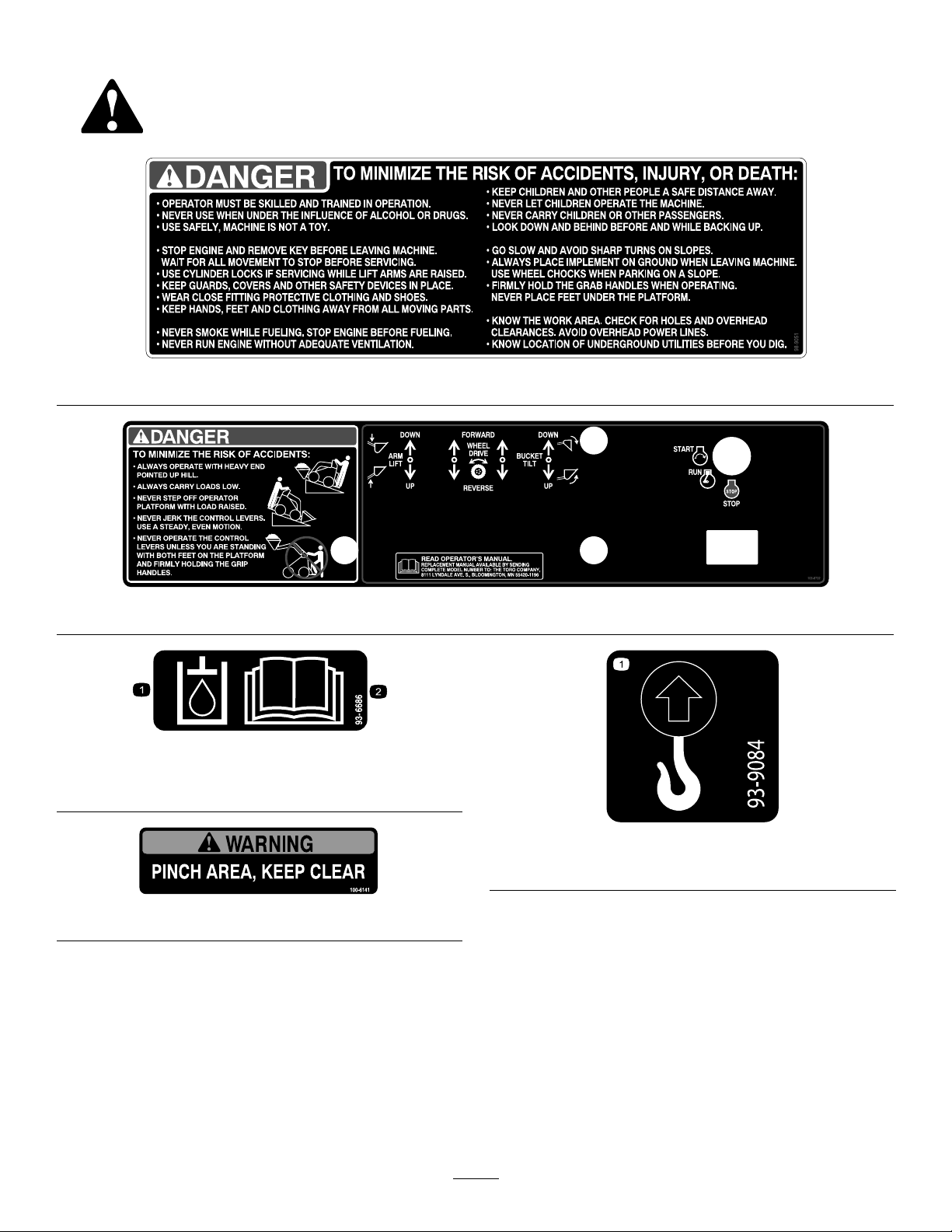
SafetyandInstructionalDecals
Safetydecalsandinstructionsareeasilyvisibletotheoperatorandarelocatednearanyareaofpotential
danger.Replaceanydecalthatisdamagedorlost.
98-9051
1.Hydraulicoil
108-9732
93–6686
2.ReadtheOperator's
Manual.
93-9084
1.Liftpoint
100-6141
7
Page 8
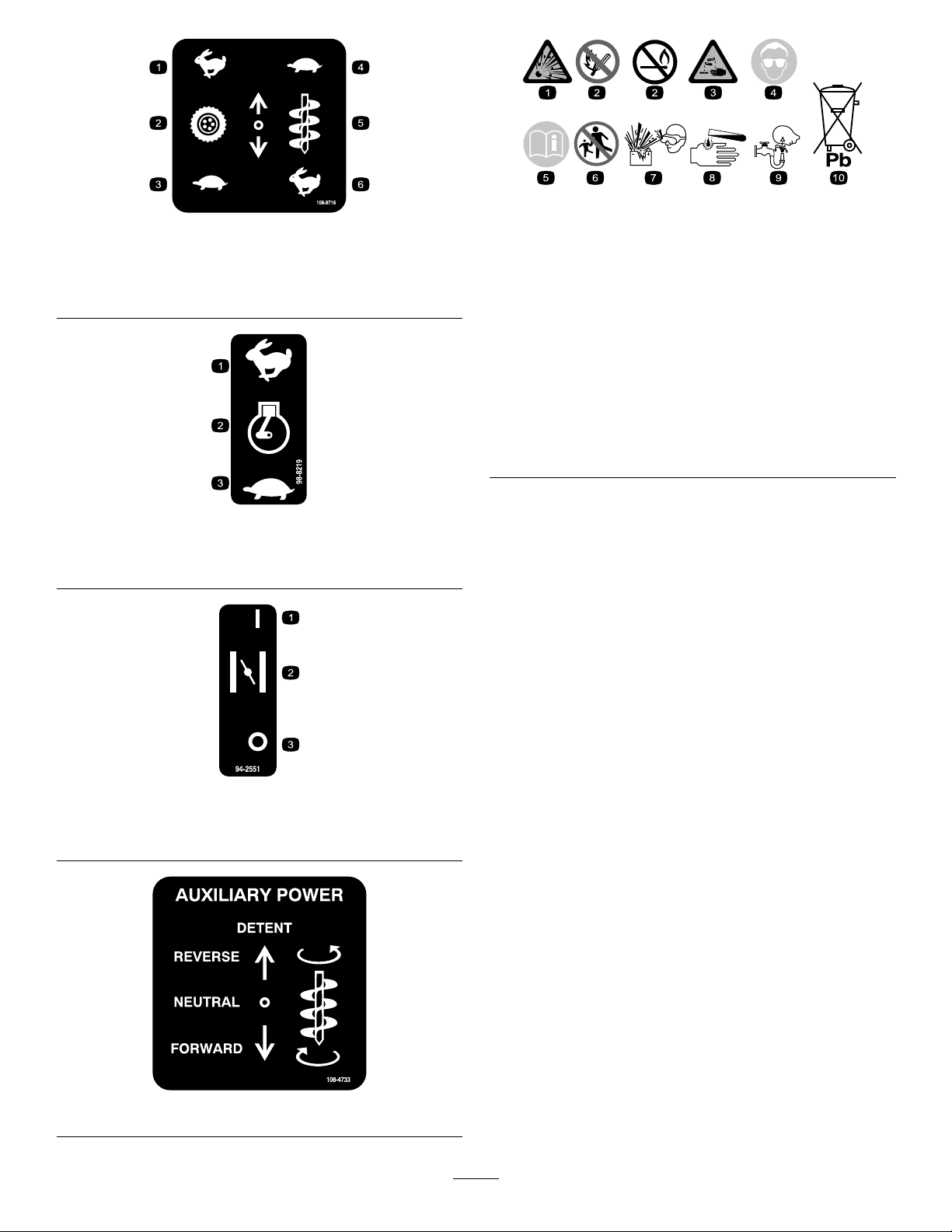
108-9716
1.Fast
2.Tractiondrive5.Attachmentspeed
3.Slow
4.Slow
6.Fast
98-8219
BatterySymbols
Someorallofthesesymbolsareonyourbattery
1.Explosionhazard
2.Nore,opename,or
smoking.
3.Causticliquid/chemical
burnhazard
4.Weareyeprotection9.Flusheyesimmediately
5.ReadtheOperator's
Manual.
6.Keepbystandersasafe
7.Weareyeprotection;
8.Batteryacidcancause
10.Containslead;donot
distancefromthebattery.
explosivegasescan
causeblindnessandother
injuries
blindnessorsevereburns.
withwaterandgetmedical
helpfast.
discard.
1.Fast
2.Throttle
3.Slow
94-2551
1.On3.Off
2.Choke
108-4733
8
Page 9
Setup
•CheckingtheEngineOilLevel(page16)
•CheckingtheHydraulicFluidLevel(page17)
•ServicingtheTractionDriveChains(page30)
1
InstallingtheValveLever
Partsneededforthisprocedure:
1
Speedselectorvalvelever
Procedure
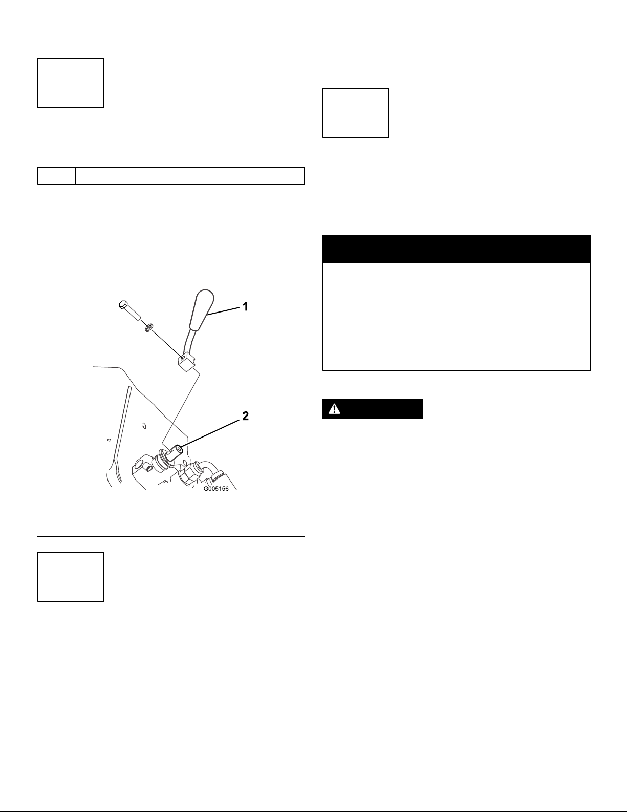
1.Removeanddiscardthenutsecuringtheboltandlock
washertothespeedselectorlever.
2.Securethelevertothespeedselectorvalveusingthe
boltandlockwasherasillustratedinFigure4.
3
ChargingtheBattery
NoPartsRequired
Procedure
WARNING
CALIFORNIA
Proposition65Warning
Batteryposts,terminals,andrelated
accessoriescontainleadandleadcompounds,
chemicalsknowntotheStateofCalifornia
tocausecancerandreproductiveharm.
Washhandsafterhandling.
WARNING
Figure4
1.Speedselectorvalvelever2.Speedselectorvalve
2
CheckingFluidLevelsand DriveChainTension
NoPartsRequired
Procedure
Beforestartingtheengineforthersttime,checktheengine
oilandhydraulicuidlevelsandthetractiondrivechain
tension.Refertothefollowingsectionsformoreinformation:
Batteryterminalsormetaltoolscouldshortagainst
metalcomponents,causingsparks.Sparkscan
causethebatterygassestoexplode,resultingin
personalinjury.
•Whenremovingorinstallingthebattery,donot
allowthebatteryterminalstotouchanymetal
partsofthetractionunit.
•Donotallowmetaltoolstoshortbetweenthe
batteryterminalsandmetalpartsofthetraction
unit.
1.Parkthetractionunitonalevelsurface,raisetheloader
arms,andinstallthecylinderlocks.
2.Stoptheengineandremovethekey.
3.Connectachargertothebattery(Figure5)andcharge
itforaminimumof1hourat6to10amps.Donot
overchargethebattery.
9
Page 10

1
2
3
4
G003792
Figure5
1.Positivepost
2.Negativepost
3.Chargerred(+)wire
4.Chargerblack(—)wire
WARNING
Chargingthebatteryproducesgassesthatcan
explode.
Neversmokenearthebatteryandkeepsparks
andamesawayfrombattery.
4.Whenthebatteryisfullycharged,unplugthecharger
fromtheelectricaloutlet,thendisconnectthecharger
leadsfromthebatteryposts(Figure5).
10
Page 11

ProductOverview
4
5
16
G019355
G005160
631524
789
Figure6
1.Mountplate5.Handles
2.Tiltcylinder
3.Auxiliaryhydrauliccouplers7.Wheel11.Aircleaner15.Fueltank
4.Loaderarms
6.Liftcylinder
8.Counterweight
Controls
9.Operatorplatform13.Controlpanel
10.Engine
12.Thighsupport
14.Liftpoints
Tostoptheengine,rotatethekeytotheoffposition.
Becomefamiliarwithallthecontrols(Figure7)beforeyou
starttheengineandoperatethetractionunit.
ThrottleLever
Movethecontrolforwardtoincreasetheenginespeedand
rearwardtodecreasespeed.
ChokeLever
Beforestartingacoldengine,movethechokeleverforward.
Aftertheenginestarts,regulatethechoketokeeptheengine
runningsmoothly.Assoonaspossible,movethechokelever
allthewayrearward.
Figure7
1.Tractioncontrollevers6.Throttlelever
2.Attachmenttiltlever
3.Loaderarmlever8.Keyswitch
4.Auxiliaryhydraulicslever9.Hourmeter
5.Speedselectorlever
7.Chokelever
Note:Awarmenginerequireslittleornochoking.
TractionControlLevers
Tomoveforward,movethetractioncontrolleversforward.
Tomoverearward,movethetractioncontrolleversrearward.
Togostraight,movebothtractioncontrolleversequally.
KeySwitch
Thekeyswitch,usedtostartandstoptheengine,hasthree
positions:off,run,andstart.
Tostarttheengine,rotatethekeytothestartposition.Release
thekeywhenenginestartsanditwillmoveautomaticallyto
therunposition.
Toturn,movetheleverlocatedonthesideyouwanttoturn
backtowardtheneutralpositionwhilekeepingtheother
leverengaged.
Thefartheryoumovethetractioncontrolleversineither
direction,thefasterthetractionunitwillmoveinthat
direction.
Tosloworstop,movethetractioncontrolleverstoneutral.
11
Page 12

AttachmentTiltLever
Totilttheattachmentforward,slowlypushtheattachment
tiltleverforward.
Totilttheattachmentrearward,slowlypulltheattachment
tiltleverrearward.
LoaderArmLever
Tolowertheloaderarms,slowlypushtheloaderarmlever
forward.
Toraisetheloaderarms,slowlypulltheloaderarmlever
rearward.
AuxiliaryHydraulicsLever
Tooperateahydraulicattachmentinforwarddirection,slowly
pulltheauxiliaryhydraulicsleverupwardandthenrearward.
Tooperateahydraulicattachmentinreversedirection,slowly
pulltheauxiliaryhydraulicsleverupwardandthenpushit
forward.Thisisalsocalledthedetentpositionbecauseitdoes
notrequireoperatorpresence.
youtochangetheoil.Afterevery100hours,thescreen
displaysSVCtoremindyoutoperformtheothermaintenance
proceduresbasedona100,200,or400hourschedule.These
reminderscomeonstartingthreehourspriortotheservice
intervaltimeandashatregularintervalsforsixhours.
SpeedSelectorLever
Movethespeedselectorlevertotheforwardpositiontoset
thetractiondrive,loaderarms,andattachmenttilttohigh
speedandtheauxiliaryhydraulicstolowspeed.
Movethespeedselectorlevertotherearwardpositiontoset
theauxiliaryhydraulicstohighspeedandthetractiondrive,
loaderarms,andattachmenttilttolowspeed.
WARNING
Ifyoumovethespeedselectorleverwhilethe
tractionunitisinmotion,thetractionunitwill
eitherstopsuddenlyoracceleratequickly.Ifyou
operatethetractionunitwiththespeedselector
leverinanintermediateposition,thetractionunit
willoperateerraticallyandmaybedamaged.You
couldlosecontrolofthetractionunitandinjure
bystandersoryourself.
•Donotmovethespeedselectorleverwhenthe
tractionunitisinmotion.
•Donotoperatethetractionunitwhenthespeed
selectorisinanyintermediateposition(i.e.,
anypositionotherthanfullyforwardorfully
rearward).
HourMeter
Thehourmeterdisplaysthenumberofhoursofoperation
thathavebeenloggedonthetractionunit.
After50hoursandthenevery100hoursthereafter(thatisat
150,250,350,etc.)thescreendisplaysCHGOILtoremind
12
Page 13

Specications
Note:Specicationsanddesignaresubjecttochangewithoutnotice.
Width
Length
Height
Weight(withoutattachmentorcounterweight)1430lb(649Kg)
Weightofthecounterweight165lb(75Kg)
Operatingcapacity(with200lboperator,thestandardbucket,andwithoutthecounterweight)515lb(234Kg)
Tippingcapacity(with200lboperator,thestandardbucket,andwithoutthecounterweight)1030lb(467Kg)
Wheelbase
Dumpheight(withstandardbucket)47inches(120cm)
Reach—fullyraised(withstandardbucket)26inches(66cm)
Heighttohingepin(narrowbucketinstandardposition)66inches(168cm)
40.5inches(103cm)
60inches(152cm)
49inches(125cm)
28inches(71cm)
Attachments/Accessories
AselectionofToroapprovedattachmentsandaccessoriesisavailableforusewiththemachinetoenhanceandexpand
itscapabilities.ContactyourAuthorizedServiceDealerorDistributororgotowww.Toro.comforalistofallapproved
attachmentsandaccessories.
Important:UseonlyT oroapprovedattachments.Otherattachmentsmaycreateanunsafeoperatingenvironment
ordamagethetractionunit.
13
Page 14

StabilityData
Thefollowingtableslistthemaximumsloperecommendedforthetractionunitinthepositionslistedinthetables.Slopesover
thelisteddegreemaycausethetractionunittobecomeunstable.Thedatainthetablesassumethattheloaderarmsarefully
lowered;raisedarmsmayaffectthestability.
Ineachattachmentmanualisasetofthreestabilityratings,oneforeachhillposition.Todeterminethemaximumslopeyou
cantraversewiththeattachmentinstalled,ndthedegreeofslopethatcorrespondstothestabilityratingsoftheattachment.
Example:IftheattachmenthasaFrontUphillratingofB,aRearUphillratingofD ,andaSideUphillratingofC,thenyou
coulddriveforwardupan18°slope,rearwardupa10°slope,orsidewaysona14°slope,aslistedinthefollowingtable.
MaximumRecommendedSlopewhen
FrontUphillRearUphill
Conguration
Tractionunitwithoutattachment
Tractionunitwithcounterweight,withoutattachment
Tractionunitwithanattachmentratedwithoneofthefollowingstabilityratings
foreachslopeposition:*
A
B
C15°16°14°
D
E
8°20°17°
5°21°17°
25°25°20°
18°19°17°
10°10°9°
5°5°5°
Operatingwith:
SideUphill
14
Page 15

Operation
Note:Determinetheleftandrightsidesofthemachinefromthenormaloperatingposition.
Important:Beforeoperating,checkthefuelandoillevel,removedebrisfromthetractionunit,andcheckthe
tirepressure.Also,ensurethattheareaisclearofpeopleanddebris.Y oushouldalsoknowandhavemarked
thelocationsofallutilitylines.
CAUTION
Youcouldfalloffoftheplatformandbeseriouslyinjuredduringoperation.
Donotmovethecontrolleversunlessyouarestandingwithbothfeetontheplatformandyourhands
areholdingthehandles.
AddingFuel
RecommendedFuel:
•Forbestresults,useonlyclean,fresh(lessthan30days
old),unleadedgasolinewithanoctaneratingof87or
higher((R+M)/2ratingmethod).
•Ethanol:Gasolinewithupto10%ethanol(gasohol)
or15%MTBE(methyltertiarybutylether)byvolume
isacceptable.EthanolandMTBEarenotthesame.
Gasolinewith15%ethanol(E15)byvolumeisnot
approvedforuse.Neverusegasolinethatcontains
morethan10%ethanolbyvolume,suchasE15
(contains15%ethanol),E20(contains20%ethanol),or
E85(containsupto85%ethanol).Usingunapproved
gasolinemaycauseperformanceproblemsand/orengine
damagewhichmaynotbecoveredunderwarranty.
•Donotusegasolinecontainingmethanol.
•Donotstorefueleitherinthefueltankorfuelcontainers
overthewinterunlessafuelstabilizerisused.
•Donotaddoiltogasoline.
Important:T oreducestartingproblems,addfuel
stabilizertothefuelallseason,mixingitwithgasoline
lessthan30daysold;runthemachinedrybeforestoring
itformorethan30days.
Donotusefueladditivesotherthanafuel
stabilizer/conditioner.Donotusefuelstabilizers
withanalcoholbasesuchasethanol,methanol,or
isopropanol.
DANGER
Incertainconditions,gasolineisextremely
ammableandhighlyexplosive.Areorexplosion
fromgasolinecanburnyouandothersandcan
damageproperty.
•Fillthefueltanksoutdoors,inanopenarea,
whentheengineiscold.Wipeupanygasoline
thatspills.
•Neverllthefueltanksinsideanenclosed
trailer.
•Donotllthefueltankscompletelyfull.Add
gasolinetothefueltankuntilthelevelis1/4to
1/2inch(6to13mm)belowthebottomofthe
llerneck.Thisemptyspaceinthetankallows
gasolinetoexpand.
•Neversmokewhenhandlinggasoline,andstay
awayfromanopenameorwheregasoline
fumesmaybeignitedbyaspark.
•Storegasolineinanapprovedcontainerand
keepitoutofthereachofchildren.Neverbuy
morethana30-daysupplyofgasoline.
•Donotoperatewithoutentireexhaustsystemin
placeandinproperworkingcondition.
15
Page 16
DANGER
Incertainconditionsduringfueling,static
electricitycanbereleasedcausingasparkwhich
canignitethegasolinevapors.Areorexplosion
fromgasolinecanburnyouandothersandcan
damageproperty.
•Alwaysplacegasolinecontainersontheground
awayfromyourvehiclebeforelling .
•Donotllgasolinecontainersinsideavehicleor
onatruckortrailerbedbecauseinteriorcarpets
orplastictruckbedlinersmayinsulatethe
containerandslowthelossofanystaticcharge.
•Whenpractical,removegas-poweredequipment
fromthetruckortrailerandrefueltheequipment
withitswheelsontheground.
•Ifthisisnotpossible,thenrefuelsuch
equipmentonatruckortrailerfromaportable
container,ratherthanfromagasolinedispenser
nozzle.
•Ifagasolinedispensernozzlemustbeused,
keepthenozzleincontactwiththerimofthe
fueltankorcontaineropeningatalltimesuntil
fuelingiscomplete.
FillingtheFuelTank
1.Parkthetractionunitonalevelsurface,lowerthe
loaderarms,andstoptheengine.
2.Removethekeyandallowtheenginetocool.
3.Cleanaroundthefueltankcapandremoveit.
Note:Thecapistetheredtothefueltank.
4.Addunleadedgasolinetothefueltank,untilthelevel
is1/4to1/2inch(6to13mm)belowthebottomof
thellerneck.
Important:Thisspaceinthetankallowsgasoline
toexpand.Donotllthefueltankcompletelyfull.
5.Installthefueltankcapsecurely,turningituntilitclicks.
6.Wipeupanygasolinethatmayhavespilled.
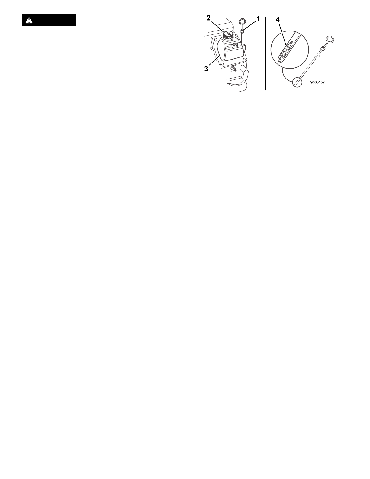
CheckingtheEngineOilLevel
Figure8
1.Oildipstick
2.Fillercap4.Metalend
4.Pulloutthedipstickandwipethemetalendclean
(Figure8).
5.Slidethedipstickfullyintothedipsticktube(Figure8).
6.Pullthedipstickoutandlookatthemetalend.
7.Iftheoillevelislow ,cleanaroundtheoilllercapand
removethecap(Figure8).
8.Slowlypouronlyenoughoilintothevalvecoverto
raisetheleveltotheF(full)mark.
Important:Donotoverllthecrankcasewithoil
becausetheenginemaybedamaged.
9.Replacethellercapanddipstick.
3.Valvecover
RemovingDebrisfromthe TractionUnit
ServiceInterval:Beforeeachuseordaily
Important:Operatingtheenginewithablockedgrass
screen,dirtyorpluggedcoolingns,and/orcooling
shroudsremoved,willresultinenginedamagefrom
overheating.
1.Parkthetractionunitonalevelsurface,raisetheloader
arms,andinstallthecylinderlocks.
2.Stoptheengineandremovethekey.
3.Cleananydebrisfromthegrillbeforeeachuseand/or
duringuse,ifrequired.
4.Wipeawaydebrisfromtheaircleanerbeforeeachuse
and/orduringuse,ifrequired.
5.Cleananydebrisbuild-upontheenginewithabrush
orblowerbeforeeachuse.
ServiceInterval:Beforeeachuseordaily
1.Parkthetractionunitonalevelsurface,lowerthe
loaderarms,andstoptheengine.
2.Removethekeyandallowtheenginetocool.
3.Cleanaroundtheoildipstick(Figure8).
Important:Itispreferabletoblowdirtout,rather
thanwashingitout.Ifwaterisused,keepitaway
fromelectricalitemsandhydraulicvalves.Do
notuseahigh-pressurewasher.High-pressure
washingcandamagetheelectricalsystemand
hydraulicvalvesordepletegrease.
6.Removeandstorethecylinderlocksandlowerthe
loaderarms.
16
Page 17
CheckingtheHydraulicFluid
1
G003793
Level
ServiceInterval:Every25hours
Checkthehydraulicuidlevelbeforetheengineisrst
startedandafterevery25operatinghours.
HydraulicTankCapacity:16.25USgallons(62l)
RefertoChangingtheHydraulicFluid(page32)forhydraulic
uidspecications.
Figure10
Important:Alwaysusethecorrecthydraulicuid.
Unspecieduidswilldamagethehydraulicsystem.
1.Removetheattachment,ifoneisinstalled.
2.Parkthetractionunitonalevelsurface,raisetheloader
arms,andinstallthecylinderlocks.
3.Stoptheengine,removethekey ,andallowtheengine
tocool.
4.Cleantheareaaroundthellerneckofthehydraulic
tank(Figure9).
5.Removethecapfromthellerneckandchecktheuid
levelonthedipstick(Figure9).
Theuidlevelshouldbebetweenthemarksonthe
dipstick.
Figure9
1.Fillerneckcap2.Dipstick
6.Ifthelevelislow,addenoughuidtoraiseittothe
properlevel.
7.Installthecaponthellerneck.
8.Removeandstorethecylinderlocksandlowerthe
loaderarms.
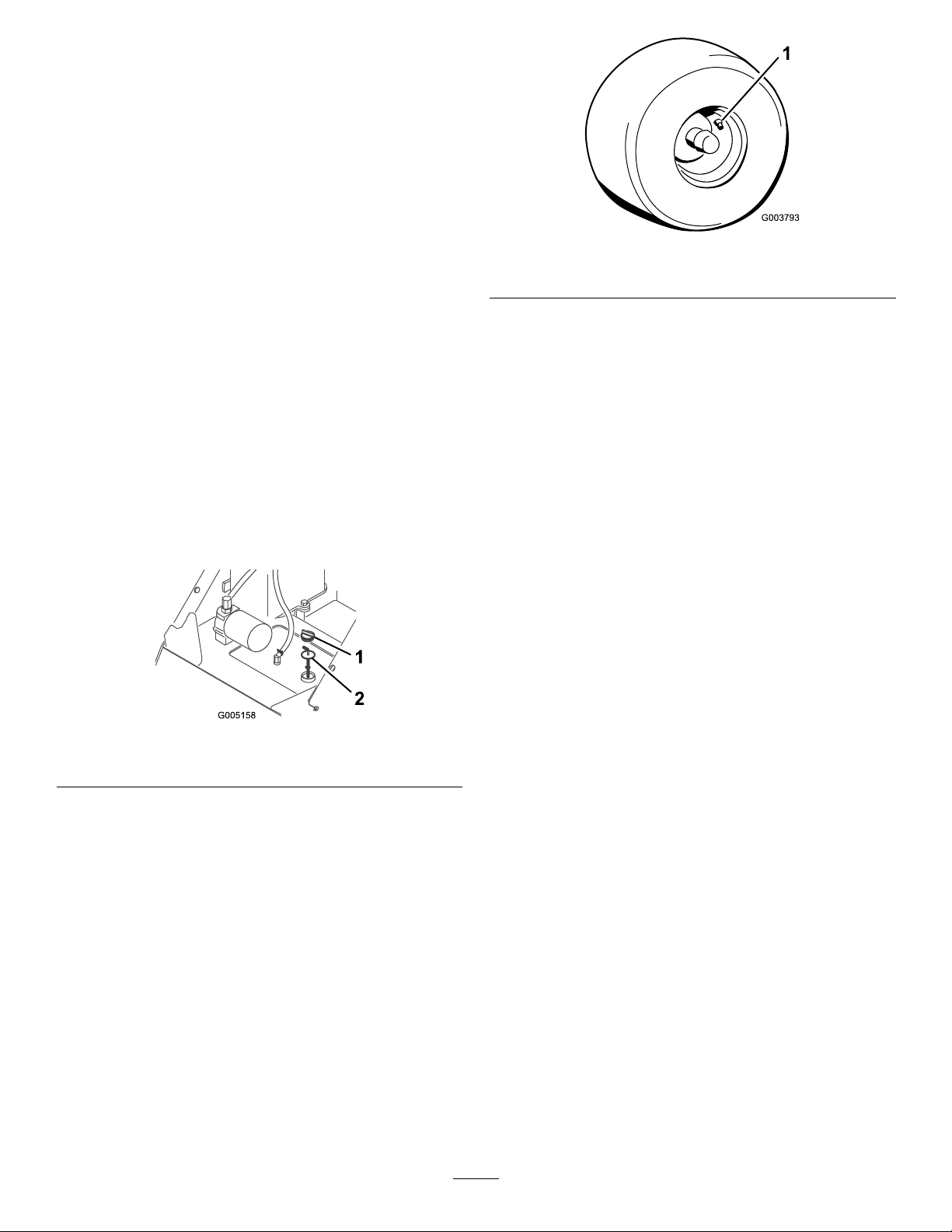
CheckingtheTirePressure
ServiceInterval:Beforeeachuseordaily
Maintaintheairpressureinthetiresasspecied.Checkthe
tireswhentheyarecoldtogetthemostaccuratereading.
Pressure:15-20psi
Note:Usealowertirepressure(15psi)whenoperatingin
sandysoilconditionstoprovidebettertractionintheloose
soil.
1.Valvestem
StartingandStoppingthe Engine
StartingtheEngine
1.Standontheplatform.
2.Ensurethattheauxiliaryhydraulicsleverisinneutral.
3.Movethechokeleverfullyforwardifyouarestartinga
coldengine.
Note:Awarmorhotenginemaynotrequirechoking.
4.Movethethrottlelevermidwaybetweenslow(turtle)
andfast(rabbit)positions.
5.Turntheignitionkeytothestartposition.Whenthe
enginesstarts,releasethekey.
Important:Donotengagethestarterformore
than10secondsatatime.Iftheenginefailsto
start,allowa30secondcool-downperiodbetween
attempts.Failuretofollowtheseinstructionscan
burnoutthestartermotor.
6.Aftertheenginestarts,graduallymovethechoke
rearward.Iftheenginestallsorhesitates,movethe
chokeforwardagainuntiltheenginewarmsup.
7.Movethethrottlelevertodesiredsetting.
Important:Ifyouruntheengineathighspeeds
whenthehydraulicsystemiscold(i.e.,whenthe
ambientairtemperatureisnearfreezingorlower),
hydraulicsystemdamagecouldoccur.When
startingtheengineincoldconditions,allowthe
enginetoruninthemiddlethrottlepositionfor
2to5minutesbeforemovingthethrottletofast
(rabbit).
Note:Ifoutdoortemperatureisbelowfreezing,store
thetractionunitinagaragetokeepitwarmerandaid
instarting.
StoppingtheEngine
1.Movethethrottleleverto3/4ofthewaytotheFast
position.
17
Page 18
2.Lowertheloaderarmstotheground.
3.Turntheignitionkeyoff.
Note:Iftheenginehasbeenworkinghardorishot,
letitrunforaminutebeforeturningtheignitionkey
off.Thishelpscooltheenginebeforeitisstopped.In
anemergency,theenginemaybestoppedimmediately.
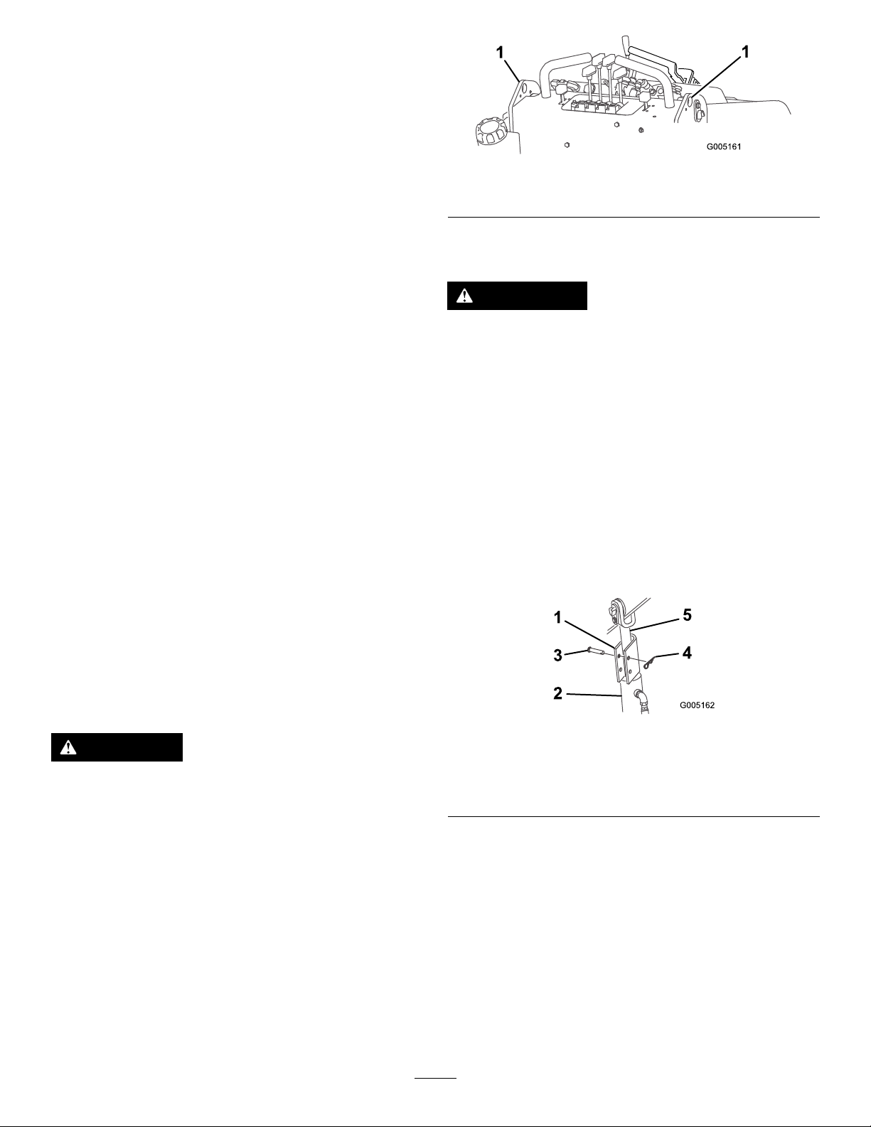
Figure11
DrivingtheTractionUnit
Thethrottlecontrolregulatestheenginespeedasmeasured
inrpm(revolutionsperminute).Placethethrottleleverinthe
fast(rabbit)positionforbestperformance.
Note:Thethrottlepositioncanbeutilizedtooperateat
slowerspeeds.
Todrivethetractionunit,completethefollowingactionsas
necessary:
•Tomoveforward,movethetractioncontrollevers
forward.
•Tomoverearward,movethetractioncontrollevers
rearward.
•Togostraight,movebothtractioncontrolleversequally.
•Toturn,movetheleverlocatedonthesideyouwantto
turntowardtheneutralpositionwhilekeepingtheother
leverengaged.
•Tosloworstop,movethetractioncontrolleversto
neutral.
Note:Thefartheryoumovethetractioncontrolleversin
eitherdirection,thefasterthetractionunitwillmoveinthat
direction.
1.Liftpoints
UsingtheCylinderLocks
WARNING
Theloaderarmsmaylowerwhenintheraised
positioncrushinganyoneunderthem.
Installthecylinderlocksbeforeperforming
maintenancethatrequiresraisedloaderarms.
InstallingtheCylinderLocks
1.Starttheengine.
2.Raisetheloaderarmstothefullyraisedposition.
3.Stoptheengine.
4.Positionaloaderarmcylinderlockovereachlift
cylinderrod(Figure12).
5.Secureeachloaderarmcylinderlockwithaclevispin
andcotterpin(Figure12).
StoppingtheTractionUnit
Tostopthetractionunit,movethetractioncontrolleversto
neutral,movethethrottlelevertoslow(turtle),lowerloader
armstotheground,andstoptheengine.Removethekey.
CAUTION
Achildoruntrainedbystandercouldattemptto
operatethetractionunitandbeinjured.
Removethekeyfromtheswitchwhenleavingthe
tractionunit,evenifjustforafewseconds.
MovingaNon-functioning TractionUnit
Important:Nevertoworpullthetractionunit.Rotating
thewheelsmanuallywillcausedamagetothehydraulic
wheelmotors.
1.Stoptheengine.
2.Liftthetractionunitofftheground,usingthetwolift
points(Figure11)andmoveitontoatrailer.
Figure12
1.Cylinderlock4.Clevispin
2.Liftcylinder5.Liftcylinderrod
3.Hairpincotter
6.Withtheengineoff,lowertheloaderarms.
Removing/StoringtheCylinderLock
1.Starttheengine.
2.Raisetheloaderarmstothefullyraisedposition.
3.Stoptheengine.
4.Removetheclevispinandcotterpinsecuringeach
cylinderlock.
5.Removethecylinderlocks.
6.Lowertheloaderarms.
18
Page 19
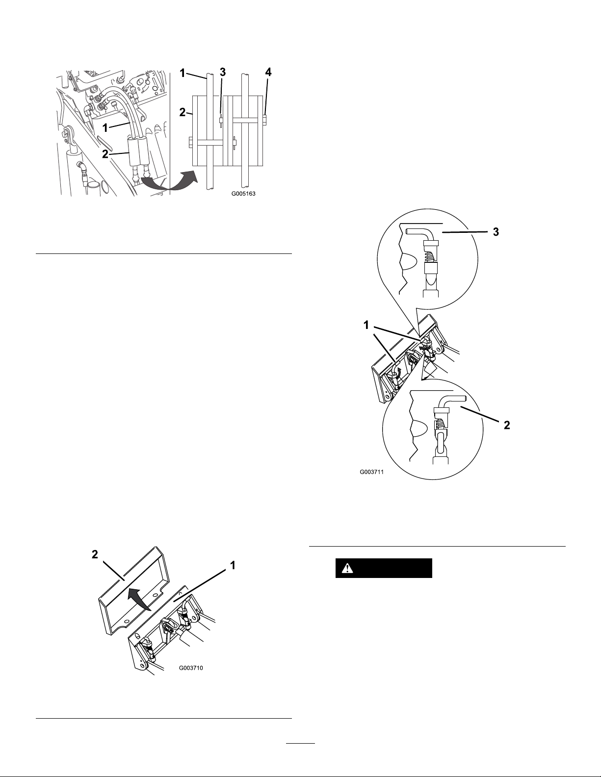
7.Installthecylinderlocksoverthehydraulichosesand
securethemwiththeclevispinsandcotterpins(Figure
13).
Figure13
1.Hydraulichoses3.Hairpincotter
2.Cylinderlocks4.Clevispin
UsingAttachments
5.Raisetheloaderarmswhiletiltingbackthemountplate
atthesametime.
Important:Theattachmentshouldberaised
enoughtocleartheground,andthemountplate
shouldbetiltedallthewayback.
6.Stoptheengine.
7.Engagethequickattachpins,ensuringthattheyare
fullyseatedinthemountplate(Figure15).
Important:Ifthepinsdonotrotatetothe
engagedposition,themountplateisnotfully
alignedwiththeholesintheattachmentreceiver
plate.Checkthereceiverplateandcleanitif
necessary.
InstallinganAttachment
Important:UseonlyToro-approvedattachments.
Attachmentscanchangethestabilityandtheoperating
characteristicsofthetractionunit.Thewarrantyofthe
tractionunitmaybevoidedifusedwithunapproved
attachments.
Important:Beforeinstallingtheattachment,ensure
thatthemountplatesarefreeofanydirtordebrisand
thatthepinsrotatefreely.Ifthepinsdonotrotatefreely,
greasethem.
1.Positiontheattachmentonalevelsurfacewithenough
spacebehindittoaccommodatethetractionunit.
2.Starttheengine.
3.Tilttheattachmentmountplateforward.
4.Positionmountplateintotheupperlipofthe
attachmentreceiverplate(Figure14).
Figure15
1.Quickattachpins(shown
inengagedposition)
2.Disengagedposition
3.Engagedposition
WARNING
Ifyoudonotfullyseatthequickattachpins
throughtheattachmentmountplate,the
attachmentcouldfalloffofthetractionunit,
crushingyouorbystanders.
Figure14
1.Mountplate2.Receiverplate
Ensurethatyourquickattachpinsarefully
seatedintheattachmentmountplate.
ConnectingtheHydraulicHoses
Iftheattachmentrequireshydraulicsforoperation,connect
thehydraulichosesasfollows:
19
Page 20

1.Stoptheengine.
2.Movetheauxiliaryhydraulicsleverforward,backward,
andbacktoneutraltorelievepressureatthehydraulic
couplers.
3.Movetheauxiliaryhydraulicsleverforwardintothe
detentposition.
4.Removetheprotectivecoversfromthehydraulic
couplersonthetractionunit.
5.Ensurethatallforeignmatteriscleanedfromthe
hydraulicconnectors.
6.Pushtheattachmentmaleconnectorintothefemale
connectoronthetractionunit.
Note:Whenyouconnecttheattachmentmale
connectorrst,youwillrelieveanypressurebuiltupin
theattachment.
3.Disengagethequickattachpinsbyturningthemto
theoutside.
4.Iftheattachmentuseshydraulics,movetheauxiliary
hydraulicsleverforward,backward,andbacktoneutral
torelievepressureatthehydrauliccouplers.
5.Iftheattachmentuseshydraulics,slidethecollarback
onthehydrauliccouplersanddisconnectthem.
Important:Connecttheattachmenthoses
togethertopreventhydraulicsystemcontamination
duringstorage.
6.Installtheprotectivecoversontothehydrauliccouplers
onthetractionunit.
7.Starttheengine,tiltthemountplateforward,andback
thetractionunitawayfromtheattachment.
WARNING
Hydraulicuidescapingunderpressurecan
penetrateskinandcauseinjury.Fluidinjected
intotheskinmustbesurgicallyremoved
withinafewhoursbyadoctorfamiliarwith
thisformofinjuryorgangrenemayresult.
•Keepyourbodyandhandsawayfrom
pinholeleaksornozzlesthatejecthigh
pressurehydraulicuid.
•Usecardboardorpapertondhydraulic
leaks,neveruseyourhands.
CAUTION
Hydrauliccouplers,hydrauliclines/valves,
andhydraulicuidmaybehot.Ifyoucontact
hotcomponentsyoumaybeburned.
•Weargloveswhenoperatingthehydraulic
couplers.
•Allowthetractionunittocoolbefore
touchinghydrauliccomponents.
SecuringtheTractionUnitfor Transport
Whentransportingthetractionunitonatrailer,alwaysuse
thefollowingprocedure:
Important:Donotoperateordrivethetractionunit
onroadways.
1.Lowertheloaderarms.
2.Stoptheengine.
3.Securethetractionunittothetrailerwithchainsor
strapsusingthetie-down/liftloops(Figure6)tosecure
therearofthetractionunitandtheloaderarms/mount
platetosecurethefrontofthetractionunit.
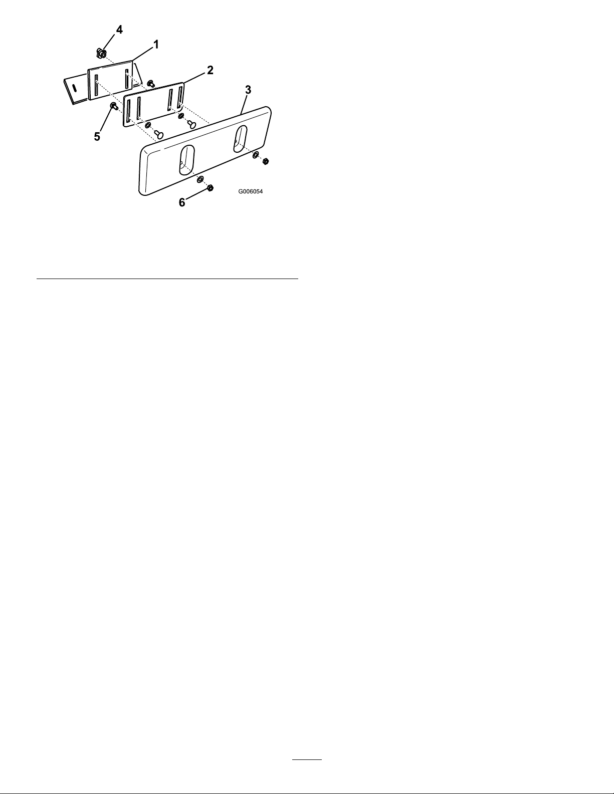
AdjustingtheThighSupport
Toadjustthethighsupport(Figure16),loosentheknobs
andraiseorlowerthesupportpadtothedesiredheight.You
canalsoobtainadditionaladjustmentbylooseningthenut
securingthepadtotheadjustmentplate,movingtheplate
upordownasneeded.Tightenallfastenerssecurelywhen
nished.
•Donottouchhydraulicuidspills.
7.Pushtheattachmentfemaleconnectorintothemale
connectoronthetractionunit.
8.Conrmthattheconnectionissecurebypullingon
thehoses.
9.Movetheauxiliaryhydraulicslevertoneutral.
RemovinganAttachment
1.Lowertheattachmenttotheground.
2.Stoptheengine.
20
Page 21
G006054
3
2
1
4
5
6
Figure16
1.Thighsupportbracket
2.Adjustmentplate
3.Thighsupportpad
4.Knobandatwasher
5.Carriagebolt
6.Locknutandatwasher
21
Page 22

Maintenance
Note:Determinetheleftandrightsidesofthemachinefromthenormaloperatingposition.
Important:Ifyouwillbetiltingthemachinemorethan
25degrees,clampofftheventhoseonthetopofthefuel
tanktopreventfuelfromfoulingthecarboncanister.
RecommendedMaintenanceSchedule(s)
MaintenanceService
Interval
Aftertherst8hours
Aftertherst50hours
Beforeeachuseordaily
Every25hours
Every50hours
Every100hours
MaintenanceProcedure
•Replacethehydrauliclter.
•T orquethewheellugnutsto50ft-lb(68N⋅m).
•Changetheengineoilandlter.
•Checktheengineoillevel.
•Removedebrisfromthetractionunit.
•Checkthetirepressure.
•Greasethetractionunit.
•Checkforloosefasteners.
•Checkthehydraulicuidlevel.
•Cleanthefoamairlterandcheckthepaperlterfordirtordamage.
•Checkthehydrauliclinesforleaks,loosettings,kinkedlines,loosemounting
supports,wear,weather,andchemicaldeterioration.
•Lubricatethetractiondrivechains.
•Checkthedrivechaintension.
•Replacethepaperairlter.
•Changetheengineoilandlter(morefrequentlywhenoperatingconditionsare
extremelydustyorsandy).
•Checkthebatteryelectrolytelevel(replacementbatteryonly).
•Checkthebatterycableconnections.
•T orquethewheellugnutsto50ft-lb(68N⋅m).
•Replacethecarboncanisterairlter.(Servicemorefrequentlyifconditionsare
extremelydustyorsandy.)
Every200hours
Every400hours
Every1,500hours
Yearly
Yearlyorbeforestorage
Important:Refertoyour
•Replacethecarboncanisterpurge-linelter.(Servicemorefrequentlywhenusing
thevibratoryplowattachment.)
•Checkthesparkplugs.
•Replacethehydrauliclter.
•Replaceallmovinghydraulichoses.
•Changethefuellter.
•Changethehydraulicuid.
•T ouchupchippedpaint
Engine Operator's Man ual
foradditionalmaintenanceprocedures.
CAUTION
Ifyouleavethekeyintheignitionswitch,someonecouldaccidentlystarttheengineandseriouslyinjure
youorotherbystanders.
Removethekeyfromtheignitionanddisconnectthewiresfromthesparkplugsbeforeyoudoany
maintenance.Setthewiresasidesothattheydonotaccidentallycontactthesparkplugs.
22
Page 23
Lubrication
EngineMaintenance
GreasingtheTractionUnit
ServiceInterval:Beforeeachuseordaily
Greaseallpivotjointsevery8operatinghoursand
immediatelyaftereverywashing.
GreaseType:General-purposegrease.
1.Lowertheloaderarmsandstoptheengine.Remove
thekey.
2.Cleanthegreasettingswitharag.
3.Connectagreaseguntoeachtting(Figure17and
Figure18).
ServicingtheAirCleaner
FoamPre-lter:Cleanevery25operatinghours.
PaperFilter:Checkevery25operatinghours.Replaceafter
every100operatinghours.
Note:Servicetheaircleanermorefrequentlyifoperating
conditionsareextremelydustyorsandy.
RemovingtheFilters
1.Lowertheloaderarms,stoptheengine,andremove
thekey.
2.Cleanaroundtheaircleanertopreventdirtfrom
gettingintotheengineandcausingdamage.
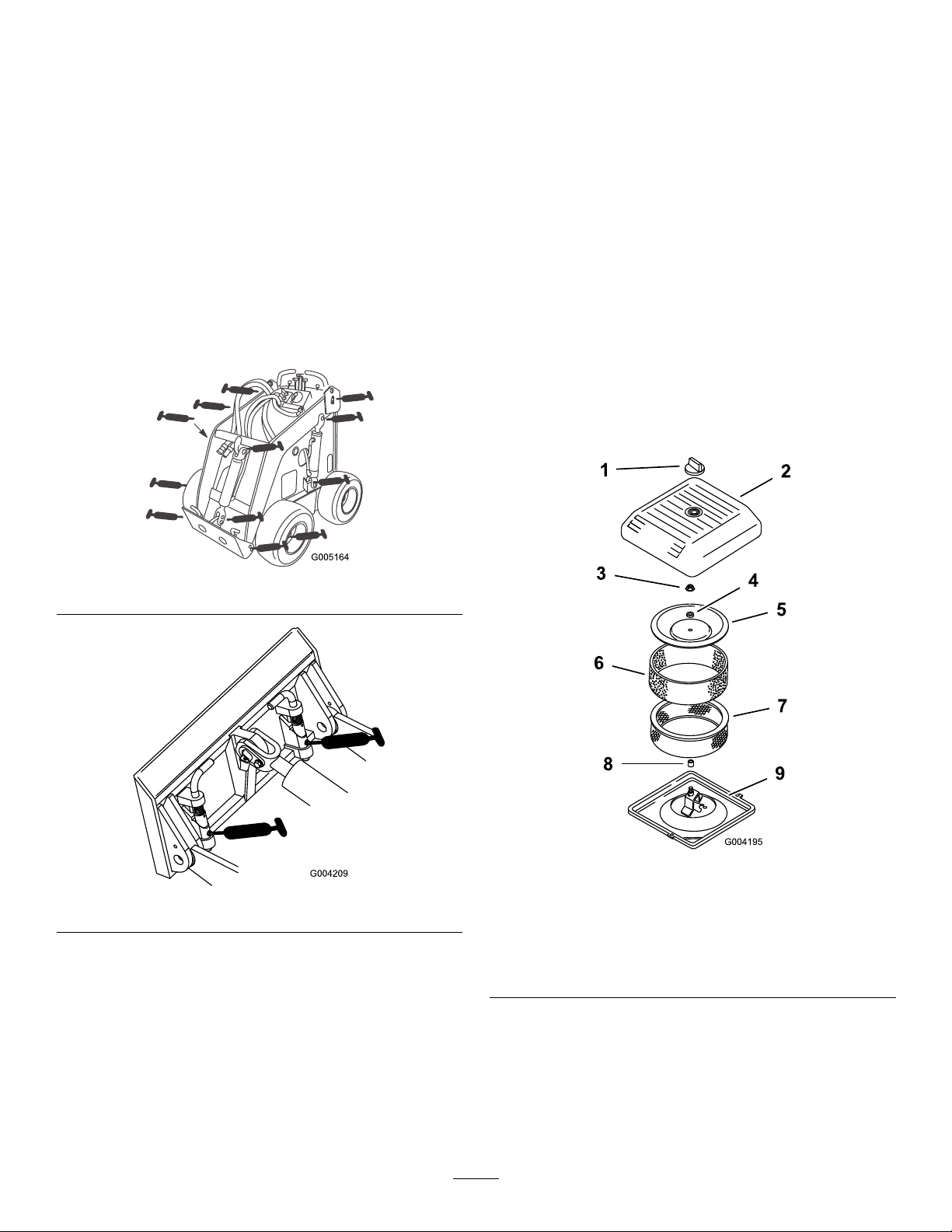
3.Unscrewtheknobandremovetheaircleanercover
(Figure19).
Figure17
Figure18
4.Pumpgreaseintothettingsuntilgreasebeginsto
oozeoutofthebearings(approximately3pumps).
Note:Atthecenterofeachfrontwheelhubisa
greasettingcoveredbyarubbercap.Fillthesettings
withgreaseuntiltheblueringaroundthettingmoves
allofthewayouttowardyou,thenreplacethecap.
5.Wipeupanyexcessgrease.
Figure19
1.Knob
2.Aircleanercover
3.Covernut
4.Spacer
5.Cover
4.Carefullyslidethefoampre-lteroffofthepaper
element(Figure19).
5.Unscrewthecovernutandremovethecover,spacer
andpaperlter(Figure19).
6.Foampre-lter
7.Paperlter
8.Rubberseal
9.Aircleanerbase
23
Page 24
Cleaning/ReplacingtheFilters
G018290
1
2
2
4
3
5
ServiceInterval:Every25hours
Every100hours
Important:Replacethefoamelementifitistornor
worn.
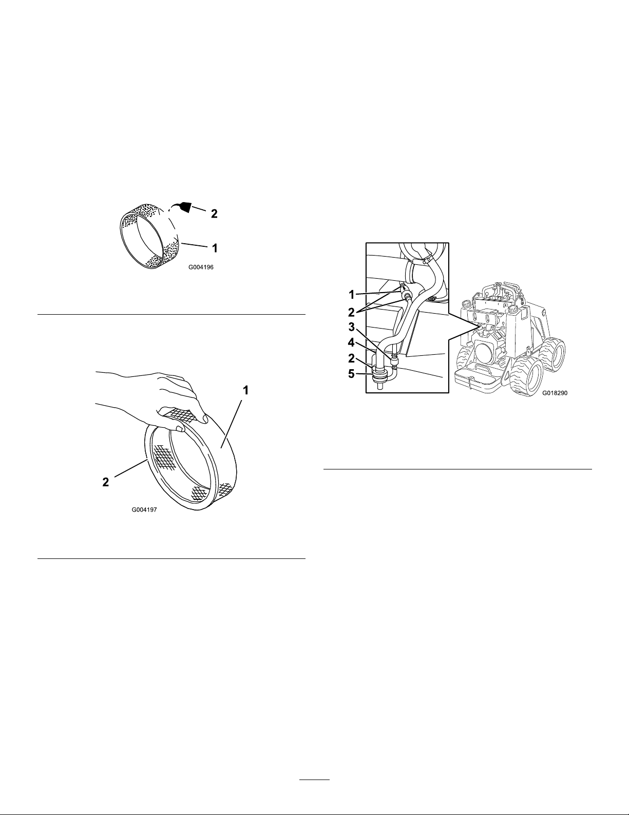
1.Washthefoampre-lterinliquidsoapandwarmwater.
Whenclean,rinseitthoroughly.
2.Drythepre-lterbysqueezingitinacleancloth(do
notwring).
3.Putoneortwoouncesofoilonthepre-lter(Figure
20).
Figure20
3.Installthecover,spacerandsecureitwiththecovernut
(Figure19).Torquethenutto95inch-lb(11N⋅m).
4.Installtheaircleanercoverandsecureitwiththeknob
(Figure19).
ServicingtheCarbonCanister
ReplacingtheCarbonCanisterAirFilter
ServiceInterval:Every200hours(Servicemorefrequentlyif
conditionsareextremelydustyorsandy.)
1.Lowertheloaderarms,stoptheengine,andremove
thekey.
2.Loosenthehoseclampabovethecarboncanisterair
lter(Figure22).
1.Foamelement
4.Squeezethepre-ltertodistributetheoil.
5.Lightlytapthepaperlteronaatsurfacetoremove
dustanddirt(Figure21).
1.Paperelement2.Rubberseal
6.Inspectthepaperlterfordirt,tears,anoilylm,and
damagetotherubberseal.
Important:Nevercleanthepaperelement.
Replacethepaperelementifitisdirtyordamaged.
2.Oil
Figure21
InstallingtheFilters
Figure22
1.Purge-linelter
2.Hoseclamp
3.Checkvalve
3.Removeanddiscardtheairlter(Figure22).
Important:Ifasmalltubesectioncomesoutof
thelargerhoseonthebarbofthelter,removeit
fromthelterandinsertitbackintothehose.
4.Installanewlterintothehoseandsecureitwiththe
hoseclamp(Figure22).
4.Hosetocarboncanister
5.Airlter
ReplacingtheCarbonCanister
Purge-lineFilter
ServiceInterval:Every200hours(Servicemorefrequently
whenusingthevibratoryplow
attachment.)
Important:Topreventenginedamage,alwaysoperate
theenginewiththecompletefoamandpaperaircleaner
assemblyinstalled.
1.Carefullyslidethefoampre-lterontothepaperlter
(Figure21).
2.Placetheaircleanerassemblyontotheaircleanerbase
(Figure19).
Note:Checkthepurge-linelteroccasionallyfordirt.Ifthe
lterappearstobedirty,replaceit.
1.Lowertheloaderarms,stoptheengine,andremove
thekey.
2.Movethespring-typehoseclampsonbothsidesofthe
carboncanisterpurge-linelterawayfromthelter
(Figure22).
24
Page 25
3.Removeanddiscardthecarbonlter(Figure22).
4.Installanewlterintothehosewiththearrowonthe
lterpointingtowardsthecheckvalveandsecureit
withthehoseclamps(Figure22).
ServicingtheEngineOil
Changeoilandlteraftertherst50operatinghoursand
thenevery100operatinghoursthereafter.
Note:Changeoilmorefrequentlywhenoperatingconditions
areextremelydustyorsandy.
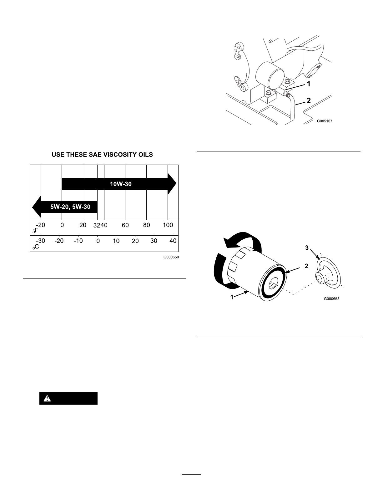
OilType:Detergentoil(APIserviceSG,SH,SJ,orhigher)
CrankcaseCapacity:w/lter,67oz(2l)
Viscosity:Seetablebelow
4.Placeoneendofahoseonthedrainvalveandthe
otherendinapan(Figure24).
Figure24
1.Oildrainvalve
5.Openthedrainvalvebyturningitcounterclockwise,
pullingoutasyouturnit(Figure24).
6.Whentheoilhasdrainedcompletely,closethedrain
valveandremovethehose.
Note:Disposeoftheusedoilatacertiedrecycling
center.
Figure23
ChangingtheOilandFilter
ServiceInterval:Aftertherst50hours
Every100hours
1.Starttheengineandletitrunforveminutes.This
warmstheoilsoitdrainsbetter.
2.Parkthetractionunitsothatthedrainsideisslightly
lowerthantheoppositesidetoensurethattheoil
drainscompletely.
3.Lowertheloaderarms,chockthewheels,stopthe
engine,andremovethekey.
CAUTION
Componentswillbehotifthetractionunithas
beenrunning.Ifyoutouchhotcomponents
youmaybeburned.
Allowthetractionunittocoolbefore
performingmaintenanceortouching
componentsunderthehood.
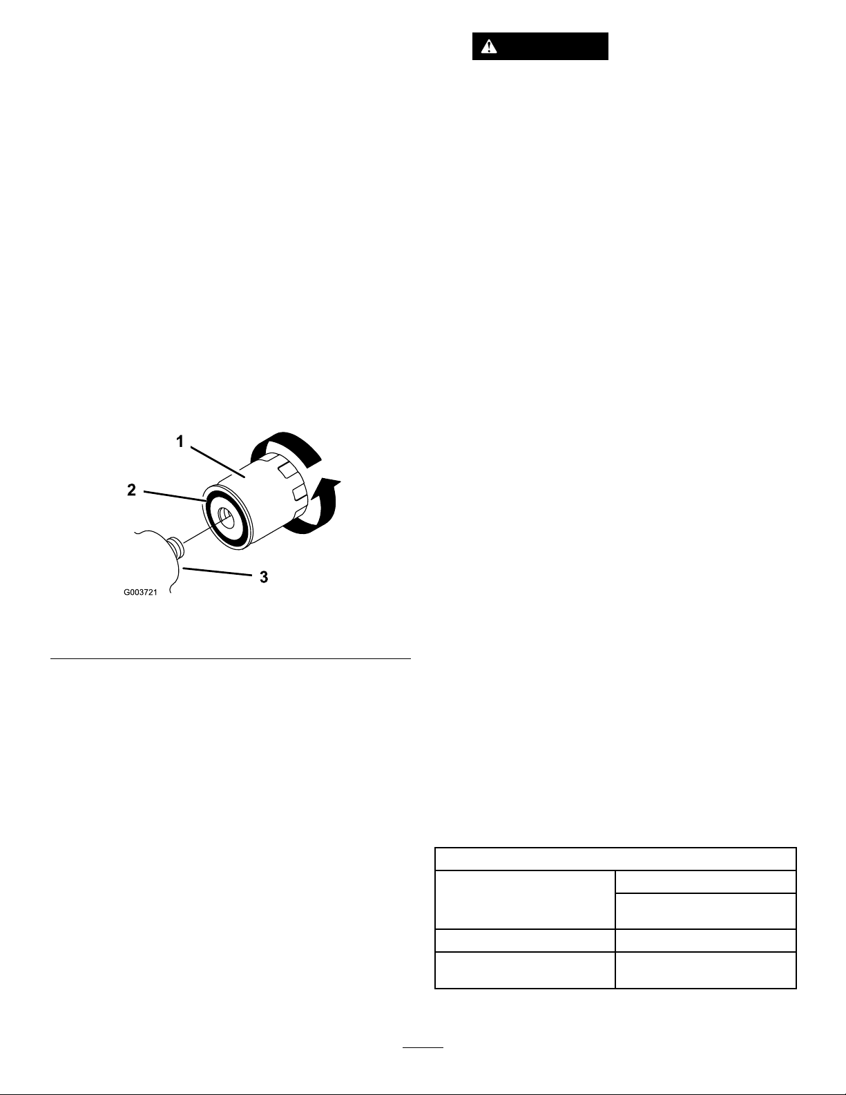
7.Removetheoldlterandwipethelteradapter(Figure
25)gasketsurface.
Figure25
1.Oillter
2.Gasket
8.Pournewoilofthepropertypeinthroughthecenter
holeofthelter.Stoppouringwhentheoilreaches
thebottomofthethreads.
9.Allowaminuteortwofortheoiltobeabsorbedby
ltermaterial,thenpourofftheexcessoil.
10.Applyathincoatofnewoiltotherubbergasketon
thereplacementlter(Figure25).
11.Installthereplacementoilltertothelteradapter.
Turntheoillterclockwiseuntiltherubbergasket
contactsthelteradapter,thentightenthelteran
additional1/2turn(Figure25).
12.Removetheoilllcapandslowlypourapproximately
80%ofthespeciedamountofoilinthroughthe
valvecover.
3.Adapter
25
Page 26

13.Checktheoillevel;refertoCheckingtheEngineOil
Level(page16).
14.SlowlyaddadditionaloiltobringtheleveltotheF
(full)markonthedipstick.
15.Replacethellcap.
ServicingtheSparkPlugs
Checkthesparkplugsafterevery200operatinghours.
Ensurethattheairgapbetweenthecenterandsideelectrodes
iscorrectbeforeinstallingeachsparkplug.Useasparkplug
wrenchforremovingandinstallingthesparkplugsanda
gappingtool/feelergaugetocheckandadjusttheairgap.
Installnewsparkplugsifnecessary.
Type:ChampionPremiumGold2071,RC12YC,or
equivalent.AirGap:0.030inch(0.76mm)
RemovingtheSparkPlugs
1.Lowertheloaderarms,stoptheengine,andremove
thekey.
2.Pullthewiresoffofthesparkplugs(Figure26).
Figure27
1.Centerelectrodeinsulator3.Airgap(nottoscale)
2.Sideelectrode
2.Checkthegapbetweenthecenterandsideelectrodes
(Figure27).
3.Bendthesideelectrode(Figure27)ifthegapisnot
correct.
InstallingtheSparkPlugs
1.Threadthesparkplugsintothesparkplugholes.
2.Tightenthesparkplugsto20ft-lb(27N⋅m).
3.Pushthewiresontothesparkplugs(Figure26).
Figure26
1.Sparkplugwire2.Sparkplug
3.Cleanaroundthesparkplugs.
4.Removebothsparkplugsandmetalwashers.
CheckingtheSparkPlugs
ServiceInterval:Every200hours
1.Lookatthecenterofbothsparkplugs(Figure27).If
youseelightbrownorgrayontheinsulator,theengine
isoperatingproperly.Ablackcoatingontheinsulator
usuallymeanstheaircleanerisdirty.
Important:Nevercleanthesparkplugs.Always
replacethesparkplugswhentheyhaveablack
coating,wornelectrodes,anoilylm,orcracks.
26
Page 27

FuelSystem
2.Lowertheloaderarms,stoptheengine,andremove
thekey.
Maintenance
ChangingtheFuelFilter
ServiceInterval:Yearly
Replacethefuellteryearly.
Important:Neverinstalladirtylter.
1.Lowertheloaderarms,stoptheengine,andremove
thekey.
2.Shutoffthefuelvalveonthebottomofthefueltank
(Figure29).
3.Clampthefuellinebetweenthefueltankandthefuel
ltertoblockthefuelow .
4.Squeezetheendsofthehoseclampstogetherandslide
themawayfromthelter(Figure28).
Figure28
1.Filter2.Hoseclamp
3.Shutoffthefuelvalveinthehosenearthebottomof
thefueltank(Figure29).
Figure29
1.Fuelvalve,open2.Fuelvalve,closed
4.Loosenthehoseclampatthefuellterandslideitup
thefuellineawayfromthelter.
5.Pullthefuellineoffofthefuellter,openthefuel
valve,loosenthefueltankcap,andallowthegasoline
todrainintoagascanordrainpan.
6.Installthefuellineontothefuellter.
7.Slidethehoseclampclosetothefuelltertosecure
thefuelline.
8.Openthefuelvalveinthehosenearthebottomofthe
fueltankasillustratedinFigure29.
5.Placeadrainpanunderthefuellinestocatchanyleaks,
thenremovethelterfromthefuellines(Figure28).
6.Installanewlterandmovethehoseclampscloseto
thelter.
7.Removetheclampblockingfuelowandopenthefuel
valve.
DrainingtheFuelTank
DANGER
Incertainconditions,gasolineisextremely
ammableandhighlyexplosive.Areorexplosion
fromgasolinecanburnyouandothersandcan
damageproperty.
•Draingasolinefromthefueltankwhenthe
engineiscold.Dothisoutdoorsinanopenarea.
Wipeupanygasolinethatspills.
•Neversmokewhendraininggasoline,andstay
awayfromanopenameorwhereasparkmay
ignitethegasolinefumes.
Note:Nowisthebesttimetoinstallanewfuellterbecause
thefueltankisempty .
1.Parkthetractionunitonalevelsurface,toensurethat
thefueltankdrainscompletely.
27
Page 28

ElectricalSystem
Maintenance
WARNING
Batteryterminalsormetaltoolscouldshort
againstmetalcomponents,causingsparks.
Sparkscancausethebatterygassesto
WARNING
explode,resultinginpersonalinjury.
CALIFORNIA
Proposition65Warning
Batteryposts,terminals,andrelated
accessoriescontainleadandleadcompounds,
chemicalsknowntotheStateofCalifornia
tocausecancerandreproductiveharm.
Washhandsafterhandling.
ReplacingtheBattery
Whenthebatterynolongerholdsacharge,replaceit.
Important:UseonlyagenuineTororeplacement
battery.
1.Parkthetractionunitonalevelsurface,raisetheloader
arms,andinstallthecylinderlocks.
2.Stoptheengineandremovethekey.
3.Removethewingnutandboltsecuringthebattery
clampandstrip(undertheclamp)andremovethe
clampandstrip(Figure30).
•Whenremovingorinstallingthebattery,
donotallowthebatteryterminalstotouch
anymetalpartsofthetractionunit.
•Donotallowmetaltoolstoshortbetween
thebatteryterminalsandmetalpartsof
thetractionunit.
4.Disconnectthenegative(black)batterycablefromthe
battery,savingtheboltandnut.
5.Disconnectthepositive(red)batterycablefromthe
battery,savingtheboltandnut.
6.Gentlypushthehydraulichosesasideandliftthe
batteryoutofthechassis.
7.Activatethenewbatteryasdirectedonthebattery
labeling.
8.Installthebatteryintothechassis(Figure30).
9.Securethebatteryinthechassis(Figure30).
10.Usingtheboltandwingnutsuppliedwiththebattery,
connectthepositive(red)cabletothepositive(+)
batterypost(Figure30).Slidetherubbercoverover
thebatterypost.
Figure30
1.Battery4.Rubbercover
2.Batteryclamp5.Negativecable
3.Positivecable
WARNING
Incorrectbatterycableroutingcoulddamage
thetractionunitandcables,causingsparks.
Sparkscancausethebatterygassesto
explode,resultinginpersonalinjury.
•Always
batterycablebeforedisconnectingthe
positive(red)cable.
•Always
cablebeforeconnectingthenegative
(black)cable.
11.Usingtheboltandwingnutsuppliedwiththebattery,
connectthenegative(black)cabletothenegative(-)
batterypost(Figure30).
Note:Ensurethatthebatterycablesdonotcontact
anysharpedgesoreachother.
disconnect
connect
thenegative(black)
thepositive(red)battery
28
Page 29

ServicingtheBattery
2
3
1
G003794
DANGER
Important:Thefollowingproceduresapplywhen
servicinga(dry)batterythathasreplacedtheoriginal
battery.Theoriginal(wet)batterydoesnotrequire
service.
Checktheelectrolytelevelinthebatteryevery100hours.
Alwayskeepthebatterycleanandfullycharged.Useapaper
toweltocleanthebatterycase.Ifthebatteryterminalsare
corroded,cleanthemwithasolutionoffourpartswaterand
onepartbakingsoda.Applyalightcoatingofgreasetothe
batteryterminalstoreducecorrosion.
Voltage:12v,450ColdCrankingAmps
CheckingtheElectrolyteLevel
ServiceInterval:Every100hours
Every100hours
1.Stoptheengineandremovethekey.
2.Removethe4boltssecuringthebatterycoverand
removeitfromoverthebattery.
3.Lookatthesideofthebattery.Theelectrolytemust
beuptotheUpperline(Figure31).Donotallowthe
electrolytetofallbelowtheLowerline(Figure31).
Batteryelectrolytecontainssulfuricacidwhichisa
deadlypoisonandcausessevereburns.
•Donotdrinkelectrolyteandavoidcontactwith
skin,eyesorclothing.Wearsafetyglassesto
shieldyoureyesandrubberglovestoprotect
yourhands.
•Fillthebatterywherecleanwaterisalways
availableforushingtheskin.
1.Removethebatteryfromthetractionunit.
Important:Neverllthebatterywithdistilled
waterwhilethebatteryisinstalledinthetraction
unit.Electrolytecouldbespilledonotherparts
andcausecorrosion.
2.Cleanthetopofthebatterywithapapertowel.
3.Removethellercapsfromthebattery(Figure31).
4.Slowlypourdistilledwaterintoeachbatterycelluntil
theelectrolytelevelisuptotheUpperline(Figure31)
onthebatterycase.
Important:Donotoverllthebatterybecause
electrolyte(sulfuricacid)cancausesevere
corrosionanddamagetothechassis.
5.Waitvetotenminutesafterllingthebatterycells.
Adddistilledwater,ifnecessary,untiltheelectrolyte
levelisuptotheUpperline(Figure31)onthebattery
case.
6.Installthebatteryllercaps.
ChargingtheBattery
WARNING
Figure31
1.Fillercaps3.Lowerline
2.Upperline
4.Iftheelectrolyteislow ,addtherequiredamountof
distilledwater;refertoAddingWatertotheBattery
(page29).
AddingWatertotheBattery
Thebesttimetoadddistilledwatertothebatteryisjust
beforeyouoperatethetractionunit.Thisletsthewatermix
thoroughlywiththeelectrolytesolution.
Chargingthebatteryproducesgassesthatcan
explode.
Neversmokenearthebatteryandkeepsparksand
amesawayfrombattery.
Important:Alwayskeepthebatteryfullycharged(1.265
specicgravity).Thisisespeciallyimportanttoprevent
batterydamagewhenthetemperatureisbelow325F
(05C).
1.Checktheelectrolytelevel;refertoCheckingthe
ElectrolyteLevel(page29).
2.Makesurethellercapsareinstalledinthebattery.
3.Chargethebatteryfor10to15minutesat25to30
ampsor30minutesat4to6amps(Figure32).Do
notoverchargethebattery.
29
Page 30

1
2
3
4
G003792
DriveSystem
Maintenance
ServicingtheTractionDrive Chains
LubricatingtheDriveChains
ServiceInterval:Every50hours
Figure32
1.Positivebatterypost
2.Negativebatterypost
4.Whenthebatteryisfullycharged,unplugthecharger
fromtheelectricaloutlet,thendisconnectthecharger
leadsfromthebatteryposts(Figure32).
5.Replacethebatterycover.
3.Red(+)chargerlead
4.Black(-)chargerlead
Lubricatethedrivechainevery50operatinghours.
1.Lowertheloaderarms,stoptheengine,andremove
thekey.
2.Applyageneralpurposeoil(10W30)ontoupperand
lowerchainspans.
3.Startthetractionunitandslowlymoveitforwardto
exposeunlubedupperandlowerchainspans.
4.Stoptheengineandremovethekey.
5.Applyoiltonewlyexposedunlubedchainspans.
CheckingtheDriveChainTension
ServiceInterval:Every50hours
Checkthedrivechaintensionbeforeusingthetractionunit
forthersttimeandevery50hoursofusethereafter.
Thedrivechainsshouldhaveabout1-1/2to2-1/2inches(3.8
to6.35cm)ofslackbetweenthebottomofthechainguard
andthebottomchainspanwhenthetopchainspanispulled
tight.Usethefollowingproceduretocheckthetension:
1.Withthebucketinstalled,loweritintothegrounduntil
thefronttiresareoffoftheground.
2.Stoptheengineandremovethekey.
3.Turnthefrontwheelforwardononesideofthe
tractionunituntilthetopspanofthedrivechainis
tight.
4.Measurethedistancebetweenthebottomofthechain
guardandthelowerchainspan(Figure33).Iftheslack
inthechainisnotwithin1-1/2to2-1/2inches(3.8
to6.35cm),adjustthetension(refertoAdjustingthe
DriveChainTension(page31)).
30
Page 31

Figure33
1.Chainguard3.1-1/2to2-1/2inches
2.Bottomspanofthechain
5.Repeatsteps3and4fortheotherdrivechain.
6.Starttheengineandraisethebuckettoreturnthefront
wheelstotheground.
AdjustingtheDriveChainTension
tosecureitinplace(Figure34)andtorquethenutto
30ft-lb(40.7N⋅m).
8.Tightenthenutssecuringtheaxleretainingbracketand
torquethemto75ft-lb(102N⋅m).
9.Repeatsteps3through8fortheotherdrivechain.
10.Starttheengineandraisethebuckettoreturnthefront
wheelstotheground.
1.Withthebucketinstalled,loweritintothegrounduntil
thefronttiresareoffoftheground.
2.Stoptheengineandremovethekey.
3.Loosenthenutssecuringtheaxleretainingbracket
(Figure34).
4.Loosenthenutonthechaintensioningboltandloosen
thebolt(Figure34).
Figure34
1.Axleretainingbracket
2.Nut4.Nut
3.Chaintensioningbolt
5.Turnthefrontwheelononesideofthetractionunit
untiltheupperspanofthedrivechainistight.
6.Adjustthechaintensioningboltuntilthedistance
betweenthebottomofthechainguardandthelower
chainspaniswithin1-1/2to2-1/2inches(3.8to6.35
cm)(Figure33).
7.Positiontheaxleretainingbrackettightagainstthe
axleandtheframe,thentightenthenutonthebolt
31
Page 32
HydraulicSystem
Maintenance
ReplacingtheHydraulicFilter
ServiceInterval:Aftertherst8hours
Every400hours
Important:Donotsubstituteanautomotiveoillteror
severehydraulicsystemdamagemayresult.
Changethehydrauliclteraftertherst8operatinghours
andthenevery400operatinghoursthereafter.
1.Positiontractionunitonalevelsurface.
2.Raisetheloaderarmsandinstallthecylinderlocks,
stoptheengine,andremovethekey.
3.Placeadrainpanunderthelter.
4.Removetheoldlter(Figure35)andwipethesurface
ofthelteradaptergasketclean.
WARNING
Hydraulicuidescapingunderpressurecan
penetrateskinandcauseinjury.Fluidinjected
intotheskinmustbesurgicallyremoved
withinafewhoursbyadoctorfamiliarwith
thisformofinjuryorgangrenemayresult.
•Keepyourbodyandhandsawayfrom
pinholeleaksornozzlesthatejecthigh
pressurehydraulicuid.
•Usecardboardorpapertondhydraulic
leaks,neveruseyourhands.
10.Checktheuidlevelinthehydraulictank(referto
CheckingtheHydraulicFluidLevel(page17))andadd
uidtoraisetheleveltomarkondipstick.Donotover
llthetank.
11.Removeandstorethecylinderlocksandlowerthe
loaderarms.
ChangingtheHydraulicFluid
Figure35
1.Hydrauliclter
5.Applyathincoathydraulicuidtotherubbergasket
onthereplacementlter(Figure35).
6.Installthereplacementhydrauliclterontothelter
adapter(Figure35).Tightenitclockwiseuntilthe
rubbergasketcontactsthelteradapter,thentighten
thelteranadditional1/2turn.
7.Cleanupanyspilleduid.
8.Starttheengineandletitrunforabouttwominutesto
purgeairfromthesystem.
9.Stoptheengineandcheckforleaks.
ServiceInterval:Yearly
HydraulicFluidSpecication:
Useonlyoneofthefollowinguidsinthehydraulicsystem:
•ToroPremiumTransmission/HydraulicTractor
Fluid(refertoyourAuthorizedT oroDealerformore
information)
•ToroPremiumAllSeasonHydraulicFluid(referto
yourAuthorizedToroDealerformoreinformation)
•IfneitheroftheaboveTorouidsareavailable,
youmayuseanotherUniversalTractorHydraulic
Fluid(UTHF),buttheymustbeonlyconventional,
petrolium-basedproducts.Thespecicationsmustfall
withinthelistedrangeforallofthefollowingmaterial
propertiesandtheuidshouldmeetthelistedindustry
standards.Checkwithyouroilsuppliertodetermineif
theoilmeetsthesespecications.
Note:Torowillnotassumeresponsibilityfordamage
causedbyimpropersubstitutions,souseonlyproducts
fromreputablemanufacturerswhowillstandbehindtheir
recommendations.
MaterialProperties
cStat40degreesC:55to62 Viscosity,ASTMD445
cStat100degreesC:9.1to
9.8
Viscosityindex,ASTMD2270
PourPoint,ASTMD97-35to-46degreesF(-37to
140to152
-43degreesC)
32
Page 33

IndustryStandards
APIGL-4,AGCOPoweruid821XL,FordNewHolland
FNHA-2-C-201.00,KubotaUDT ,JohnDeereJ20C,Vickers
35VQ25andVolvoWB-101/BM.
Storage
1.Lowertheloaderarms,stoptheengine,andremove
thekey.
Note:Manyhydraulicuidsarealmostcolorless,making
itdifculttospotleaks.Areddyeadditiveforthe
hydraulicsystemoilisavailablein2/3oz(20ml)bottles.
Onebottleissufcientfor4-6gal(15-22l)ofhydraulic
oil.Orderpartno.44-2500fromyourAuthorizedToro
Dealer.
1.Positionthetractionunitonalevelsurface.
2.Raisetheloaderarmsandinstallthecylinderlocks.
3.Stoptheengineandremovethekey.
4.Placealargedrainpanunderthetractionunitthatcan
holdatleast17USgallons(67l).
5.Removethedrainplugfromthebottomofthe
hydraulictankandallowtheuidtocompletelydrain
out.
6.Installthedrainplug.
7.Fillthehydraulictankwithapproximately15US
gallons(57L)ofhydraulicuidasspeciedabove;
refertoCheckingtheHydraulicFluidLevel(page17).
Note:Disposeofusedoilatacertiedrecycling
center.
8.Removeandstorethecylinderlocksandlowerthe
loaderarms.
2.Removedirtandgrimefromtheexternalpartsofthe
entiretractionunit,especiallytheengine.Cleandirt
andchafffromtheoutsideoftheengine'scylinder
headnsandblowerhousing.
Important:Youcanwashthetractionunitwith
milddetergentandwater.Donotpressurewash
thetractionunit.Avoidexcessiveuseofwater,
especiallynearthecontrolpanel,engine,hydraulic
pumps,andmotors.
3.Servicetheaircleaner;referto(page).
4.Greasethetractionunit;refertoGreasingtheTraction
Unit(page23).
5.Changetheengineoil;refertoChangingtheOiland
Filter(page25).
6.Removethesparkplugsandchecktheconditionof
each;refertoServicingtheSparkPlugs(page26).
7.Withthesparkplugsremovedfromtheengine,pour
twotablespoonsofengineoilintoeachsparkplughole.
8.Placeragsoverthesparkplugholestocatchanyoil
spray,thenusethestartertocranktheengineand
distributetheoilinsidethecylinder.
9.Installthesparkplugs,butdonotinstallthewireson
thesparkplugs.
CheckingtheHydraulicLines
ServiceInterval:Every25hours
Every1,500hours
Afterevery25operatinghours,checkthehydrauliclinesand
hosesforleaks,loosettings,kinkedlines,loosemounting
supports,wear,weather,andchemicaldeterioration.Replace
allmovinghydraulichosesevery1500hoursor2years,which
evercomesrst.Makenecessaryrepairsbeforeoperating.
WARNING
Hydraulicuidescapingunderpressurecan
penetrateskinandcauseinjury.Fluidinjectedinto
theskinmustbesurgicallyremovedwithinafew
hoursbyadoctorfamiliarwiththisformofinjury
organgrenemayresult.
•Keepyourbodyandhandsawayfrompin
holeleaksornozzlesthatejecthighpressure
hydraulicuid.
•Usecardboardorpapertondhydraulicleaks,
neveruseyourhands.
10.Checkthetirepressure;refertoCheckingtheTire
Pressure(page17).
11.Chargethebattery;referto3ChargingtheBattery
(page9).
12.Forstorageover30days,preparethetractionunitas
follows:
A.Addapetroleumbasedstabilizer/conditionerto
fuelinthetank.Followmixinginstructionsfrom
stabilizermanufacturer(1oz.pergallon).Do
notuseanalcoholbasedstabilizer(ethanol
ormethanol).
Note:Afuelstabilizer/conditionerismost
effectivewhenmixedwithfreshgasolineandused
atalltimes.
B.Runtheenginetodistributeconditionedfuel
throughthefuelsystem(5minutes).
C.Stoptheengine,allowittocool,anddrainthefuel
tanks;refertoDrainingtheFuelTank.
D.Starttheengineandrunituntilitstops.
E.Choketheengine.
F.Startandruntheengineuntilitwillnotstartagain.
33
Page 34

G.Disposeoffuelproperly.Recycleasperlocal
codes.
Important:Donotstorestabilizer/conditioned
gasolineover90days.
13.Checkandtightenallbolts,nuts,andscrews.Repairor
replaceanypartthatisdamagedordefective.
14.Paintallscratchedorbaremetalsurfaces.Paintis
availablefromyourAuthorizedServiceDealer.
15.Storethetractionunitinaclean,drygarageorstorage
area.Removethekeyfromtheignitionswitchand
keepitinamemorableplace.
16.Coverthetractionunittoprotectitandkeepitclean.
Important:Whenremovingthetractionunitfrom
storage,chargethebattery;referto3Chargingthe
Battery(page9).
34
Page 35

Troubleshooting
Problem
Thestarterdoesnotcrank
Theenginewillnotstart,startshard,or
failstokeeprunning.
Theenginelosespower.
PossibleCauseCorrectiveAction
1.Theauxiliaryhydraulicsleverisnotin
theneutralposition.
2.Thebatteryisdischarged.
3.Theelectricalconnectionsare
corrodedorloose.
4.Therelayorswitchisdamaged.
1.Thefueltankisempty.1.Fillthefueltankwithgasoline.
2.Thechokeisnoton.
3.Theaircleanerisdirty.
4.Thesparkplugwiresarelooseor
disconnected.
5.Thesparkplugsarepitted,fouled,or
thegapisincorrect.
6.Thereisdirtinthefuellter.6.Replacethefuellter.
7.Dirt,water,orstalefuelisinfuel
system.
1.Theengineloadisexcessive.1.Reducegroundspeed.
2.Theaircleanerisdirty.
3.Theoillevelincrankcaseislow.
4.Thecoolingnsandairpassages
undertheengineblowerhousingare
plugged.
5.Thesparkplugsarepitted,fouled,or
thegapisincorrect.
6.Thereisdirtinthefuellter.6.Replacethefuellter.
7.Dirt,water,orstalefuelisinfuel
system.
1.Movethelevertotheneutralposition.
2.Chargethebatteryorreplaceit.
3.Checktheelectricalconnectionsfor
goodcontact.
4.ContactyourAuthorizedService
Dealer.
2.Movethechokeleverfullyforward.
3.Cleanorreplacetheaircleaner
elements.
4.Installthewiresonthesparkplugs.
5.Installnew,correctlygappedspark
plugs.
7.ContactyourAuthorizedService
Dealer.
2.Cleanorreplacetheaircleaner
elements.
3.Checkandaddoiltothecrankcase.
4.Removeanyobstructionsfromthe
coolingnsandairpassages.
5.Installnew,correctlygappedspark
plugs.
7.ContactyourAuthorizedService
Dealer.
Theengineoverheats.
Abnormalvibration.1.Theenginemountingboltsareloose.1.Tightentheenginemountingbolts.
Thetractionunitdoesnotdrive.
Whenatrest,theloaderarmscreep
downwardmorethan3inchesperhour
(lessthan3inchesanhourisnormalfor
thistractionunit).
Whenatrest,loaderarmssettledownward
2inchesquicklyandthenstop.
1.Theengineloadisexcessive.1.Reducegroundspeed.
2.Theoillevelinthecrankcaseislow.
3.Thecoolingnsandairpassages
undertheengineblowerhousingare
plugged.
1.Thehydraulicuidlevellow.1.Checkandaddhydraulicuid.
2.Thehydraulicsystemisdamaged.
1.Thevalvespoolisleaking
1.Thecylindersealsareleaking1.Replacetheseals.
2.Checkandaddoiltothecrankcase.
3.Removeanyobstructionsfromthe
coolingnsandairpassages.
2.ContactyourAuthorizedService
Dealer.
1.ContactyourAuthorizedService
Dealer.
35
Page 36
Schematics
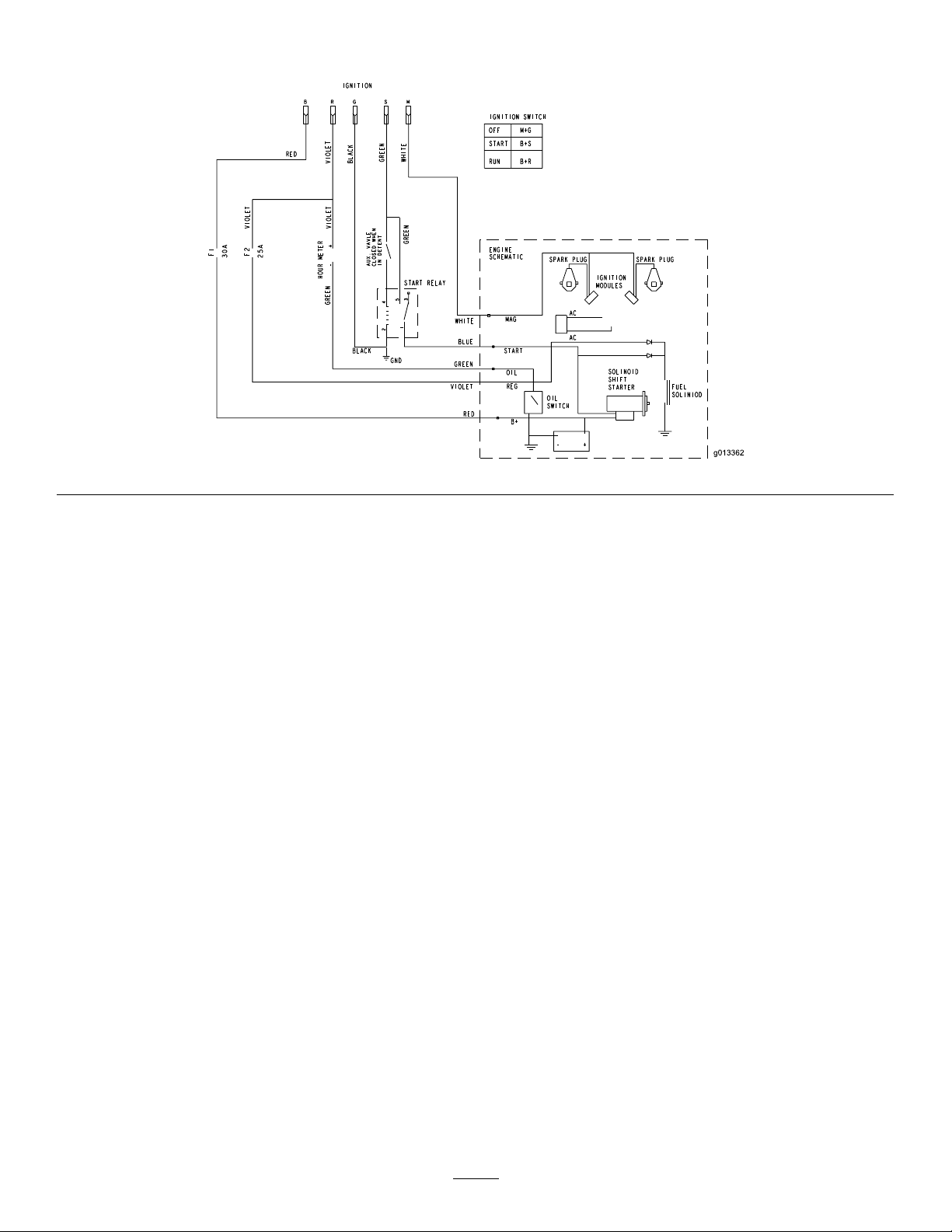
ElectricalSchematic(Rev .A)
36
Page 37
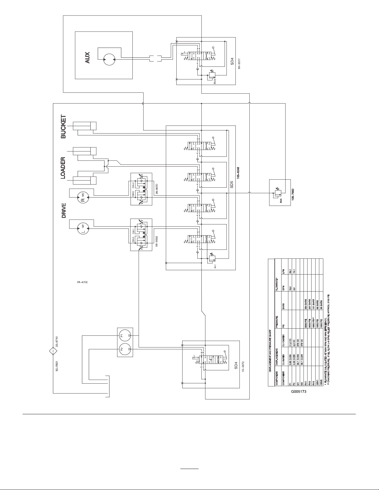
HydraulicSchematic(Rev .A)
37
Page 38

Notes:
38
Page 39

Notes:
39
Page 40

TheToroWarranty
AOne-Y earLimitedWarranty
CompactUtilityEquipment
(CUE)Products
ConditionsandProductsCovered
TheT oroCompanyanditsafliate,ToroWarrantyCompany ,pursuantto
anagreementbetweenthem,jointlywarrantyourToroCompactUtility
Equipment(“Product”)tobefreefromdefectsinmaterialsorworkmanship.
Thefollowingtimeperiodsapplyfromthedateofpurchase:
ProductsWarrantyPeriod
ProSneak
CompactToolCarriers,
Trenchers,StumpGrinders,
andAttachments
KohlerEngines3years
AllotherEngines2years
Whereawarrantableconditionexists,wewillrepairtheProductatnocost
toyouincludingdiagnosis,labor,andparts.
*
SomeenginesusedonToroProductsarewarrantedbytheenginemanufacturer .
1yearor1000operatinghours,
whicheveroccursrst
*
*
InstructionsforObtainingWarrantyService
IfyouthinkthatyourT oroProductcontainsadefectinmaterialsor
workmanship,followthisprocedure:
1.ContactanyAuthorizedT oroCompactUtilityEquipment(CUE)
ServiceDealertoarrangeserviceattheirdealership.T olocatea
dealerconvenienttoyou,accessourwebsiteatwww .T oro.com.You
mayalsocallourToroCustomerCareDepartmenttollfreeatthe
numberbelow.
2.Bringtheproductandyourproofofpurchase(salesreceipt)tothe
ServiceDealer.
3.IfforanyreasonyouaredissatisedwiththeServiceDealer’s
analysisorwiththeassistanceprovided,contactusat:
SWSCustomerCareDepartment
ToroWarrantyCompany
811 1LyndaleAvenueSouth
Bloomington,MN55420-1196
TollFree:888-384-9940
OwnerResponsibilities
YoumustmaintainyourT oroProductbyfollowingthemaintenance
proceduresdescribedintheOperator’sManual.Suchroutinemaintenance,
whetherperformedbyadealerorbyyou,isatyourexpense.Parts
scheduledforreplacementasrequiredmaintenance(“MaintenanceParts”),
arewarrantedfortheperiodoftimeuptothescheduledreplacementtime
forthatpart.Failuretoperformrequiredmaintenanceandadjustmentscan
begroundsfordisallowingawarrantyclaim.
ItemsandConditionsNotCovered
Notallproductfailuresormalfunctionsthatoccurduringthewarrantyperiod
aredefectsinmaterialsorworkmanship.Thisexpresswarrantydoesnot
coverthefollowing:
•Productfailureswhichresultfromtheuseofnon-T ororeplacement
parts,orfrominstallationanduseofadd-on,modied,orunapproved
accessories
•Productfailureswhichresultfromfailuretoperformrequired
maintenanceand/oradjustments
•ProductfailureswhichresultfromoperatingtheProductinanabusive,
negligentorrecklessmanner
•Partssubjecttoconsumptionthroughuseunlessfoundtobedefective.
Examplesofpartswhichareconsumed,orusedup,duringnormal
productoperationinclude,butarenotlimitedto,belts,wipers,spark
plugs,tires,lters,gaskets,wearplates,seals,O-rings,drivechains,
clutches.
•Failurescausedbyoutsideinuence.Itemsconsideredtobeoutside
inuenceinclude,butarenotlimitedto,weather,storagepractices,
contamination,useofunapprovedcoolants,lubricants,additives,or
chemicals,etc.
•Normal“wearandtear”items.Normal“wearandtear”includes,butis
notlimitedto,wornpaintedsurfaces,scratcheddecals,etc.
•Repairsnecessaryduetofailuretofollowrecommendedfuel
procedure(consultOperator'sManualformoredetails)
–Removingcontaminantsfromthefuelsystemisnotcovered
–Useofoldfuel(morethanonemonthold)orfuelwhichcontains
morethan10%ethanolormorethat15%MTBE
–Failuretodrainthefuelsystempriortoanyperiodofnon-use
overonemonth
•Anycomponentcoveredbyaseparatemanufacturer’swarranty
•Pickupanddeliverycharges
GeneralConditions
RepairbyanAuthorizedT oroCompactUtilityEquipment(CUE)Service
Dealerisyoursoleremedyunderthiswarranty .
NeitherTheToroCompanynorToroWarrantyCompanyisliablefor
indirect,incidentalorconsequentialdamagesinconnectionwiththe
useoftheToroProductscoveredbythiswarranty,includingany
costorexpenseofprovidingsubstituteequipmentorserviceduring
reasonableperiodsofmalfunctionornon-usependingcompletionof
repairsunderthiswarranty .Allimpliedwarrantiesofmerchantability
andtnessforusearelimitedtothedurationofthisexpresswarranty.
Somestatesdonotallowexclusionsofincidentalorconsequential
damages,orlimitationsonhowlonganimpliedwarrantylasts,sothe
aboveexclusionsandlimitationsmaynotapplytoyou.
Thiswarrantygivesyouspeciclegalrights,andyoumayalsohaveother
rightswhichvaryfromstatetostate.
ExceptfortheenginewarrantycoverageandtheEmissionswarranty
referencedbelow,ifapplicable,thereisnootherexpresswarranty .The
EmissionsControlSystemonyourProductmaybecoveredbyaseparate
warrantymeetingrequirementsestablishedbytheU.S.Environmental
ProtectionAgency(EPA)ortheCaliforniaAirResourcesBoard(CARB).
ThehourlimitationssetforthabovedonotapplytotheEmissions
ControlSystemWarranty.RefertotheCaliforniaEmissionControl
WarrantyStatementsuppliedwithyourProductorcontainedintheengine
manufacturer’sdocumentationfordetails.
CountriesOtherthantheUnitedStatesorCanada
CustomerswhohavepurchasedT oroproductsoutsidetheUnitedStatesorCanadashouldcontacttheirToroDistributor(Dealer)toobtainguarantee
policiesforyourcountry,province,orstate.IfforanyreasonyouaredissatisedwithyourDistributor'sserviceorhavedifcultyobtainingguarantee
information,contacttheT oroimporter .Ifallotherremediesfail,youmaycontactusatToroWarrantyCompany .
AustralianConsumerLaw:AustraliancustomerswillnddetailsrelatingtotheAustralianConsumerLaweitherinsidetheboxoratyourlocalT oro
Dealer.
374-0261RevG
 Loading...