

Page 1

DH200,DH210,andDH220LawnTractors
SerialNo.280000001andUp
LooseParts
Usethechartbelowtoverifythatallpartshavebeenshipped.
FormNo.3360-473RevB
SetupInstructions
ProcedureDescription
1
2
3
4
5
6
7
SteeringWheel
LockWasher1
Nut1
Seat
Bolts2
FlatWashers2
SpringWashers
TrailerHitch1
Bolts2
Nuts2
CollectorCover
GrassCollector—PartiallyAssembled
GrassBag
FastenerPackage1
ArrowDecal1
Nopartsrequired
Nopartsrequired
Nopartsrequired
Qty.
Use
1
Installingthesteeringwheel
1
Installingtheseat
2
Attachingthetrailerhitch
1
1
1
–
–
–
Assemblingthegrasscollector
Checkingtheoillevel
Activatingthebattery
Fillingthefueltank
8
9
10
11
12
13
©2009—TheToro®Company
8111LyndaleAvenueSouth
Bloomington,MN55420
Nopartsrequired
Nopartsrequired
Keys2
Nopartsrequired
Operator’sManual
EngineOperator’sManual
CerticateofConformance
Registeratwww.Toro.com.
–
–
–
1
1
1
Checkingthetirepressure
Lubricatingthemachine
UsingintheignitionandKeyChoice™
switch
Checkthesafetysystem
Readingbeforeoperatingthemachine
CEconformance
OriginalInstructions(EN)
PrintedintheUSA
AllRightsReserved
Page 2
1
2
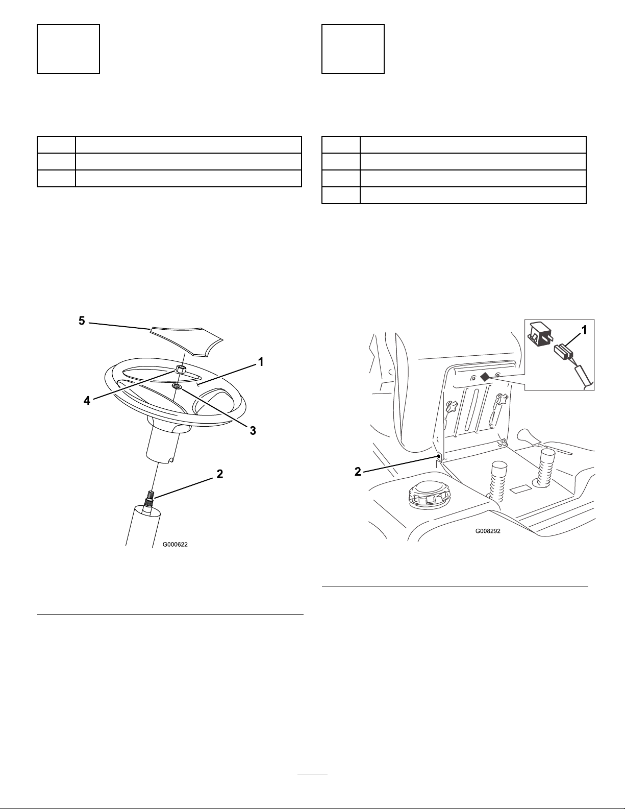
InstallingtheSteeringWheel
Partsneededforthisprocedure:
1
SteeringWheel
1LockWasher
1Nut
Procedure
1.Positionthefrontwheelsstraightahead.
2.Removethelogocoverbyreleasingthe3latches
fromthebacksidewithascrewdriver.
3.Lineupthecenterspoketowardtheseatandposition
thesteeringwheelontotheshaftspline(Figure1).
InstallingtheSeat
Partsneededforthisprocedure:
1
Seat
2Bolts
2FlatWashers
2
SpringWashers
Procedure
1.Removetheplasticcoverfromtheseatanddiscardit.
2.Loosenthetwoboltsontheseathinges.
3.Settheseatinplaceandsecureitwiththetwobolts,
springwashers,andatwashers(Figure2).
Figure1
1.Centerspoke
2.Shaftspline
3.Lockwasher
4.Securethesteeringwheelwithalockwasherandnut
(Figure1).
5.Torquethesteeringwheelnutto50ft-lb(37N-m).
6.Snapthelogocoverintoplace(Figure1).
4.Nut
5.Logocover
Figure2
1.Safetyswitch
4.Ensurethatthesafetyswitchisconnectedtotheseat
(Figure2).
2
2.Boltandwashers
Page 3
3
4
AttachingtheTrailerHitch
Partsneededforthisprocedure:
1TrailerHitch
2Bolts
2Nuts
Procedure
1.Lineuptheholesinthetrailerhitchwiththeholesin
themachineframe.
2.Attachthehitchwithtwoboltsandnuts(Figure3).
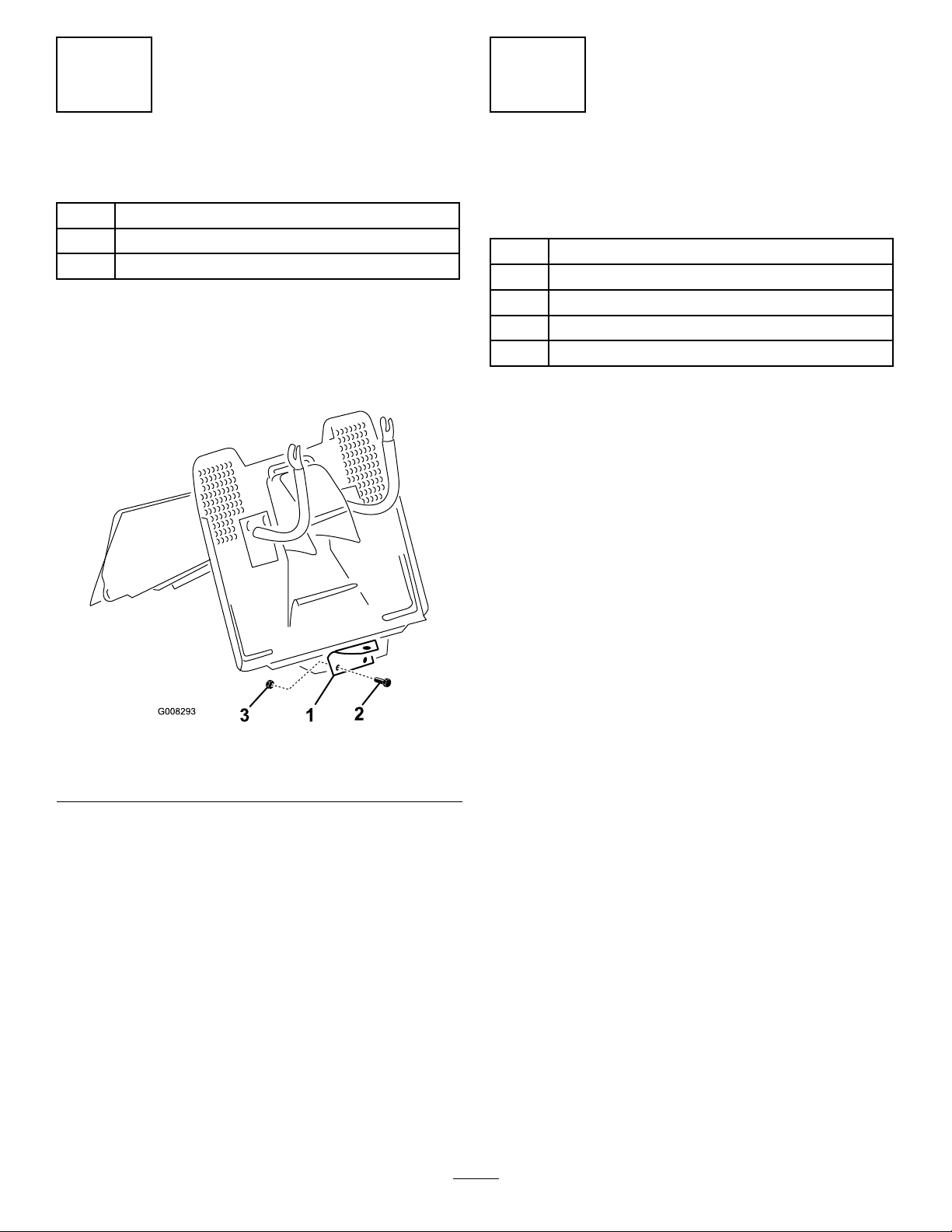
AssemblingtheGrass
Collector
Partsneededforthisprocedure:
1
CollectorCover
1
GrassCollector—PartiallyAssembled
1
GrassBag
1FastenerPackage
1ArrowDecal
Procedure
1.Tiltthefronttubeofthepartiallyassembled
collector.
2.Aligntheupperholeswiththeholesontheupper
tube.Looselyfastenthetubestogetherwiththe
upperbolts(Figure4).
Figure3
1.Trailerhitch3.Nut
2.Bolt
3
Page 4

12.Placethecoveronthegrasscollector.
13.Alignthecoverwiththerearfenderbyadjustingthe
rearmachinesupportsuntilthereisaproperseal
betweenthecoverandthecollector.
14.Tightentherearmachinesupportbolts.
15.Removethegrasscollectorfromthemachine.
16.Tightenallscrewssecurely.
17.Usetheplasticextrusionsonthebagedgestox
thebagtotheframetube.
18.Insertthedumpingleverthroughtheholeofthe
coverandsecureitwiththeM5x12screwandM5
nut(insidethetube)(Figure4).
19.Installthegrasscollectortothemachine(referto
theOperator’sManual).
20.Whenthegrasscollectorisproperlypositioned,
placethearrowdecaldirectlyoppositethearrow
symbolontherearofthemachine.
Figure4
1.Cover
2.Upperbolts
3.Fronttube9.Bottomtube
4.M5boltsandnuts10.Bag
5.Leftandrightsupports
6.Screws
3.Placethecollectorontherearmachinesupports
(refertotheOperator’sManual)andalignthecollector
framewiththemachinefenders.
4.Tightentheupperbolts(Figure4).
5.Stretchthebagandputitovertherearhandle
(Figure4).
6.Insertthebottomtubeintothebag(Figure4).
7.Insertthecornersupportsunderthetoptube.
8.Fastenthecornersupportstothetopandbottom
tubesusingtheM5boltsandnutsfromunderthe
collectorcover(Figure4).
7.Lowerbrace
8.Cornerupports
11.Dumpinglever
12.Rearhandle
5
CheckingtheOilLevel
NoPartsRequired
Procedure
Themachinecomesfromthefactorywithoilinthe
enginecrankcase;however,itmaybenecessarytoadd
oil.RefertotheOperator’sManualforoiltype,viscosity,
andcrankcasecapacity.Addonlyenoughoiltoraisethe
leveltotheFullmarkonthedipstick.
6
ActivatingtheBattery
NoPartsRequired
9.FastenthebottomtubetothefronttubewithM5
boltsandnuts(Figure4).
10.Tilttheleftandrightsupportsrearward.
11.Placethelowerbraceontheoutsideofthebag
andsecureittotheleftandrightsupportswiththe
screws(Figure4).
Procedure
1.Removethebatteryfromthemachine;refertothe
Operator’sManual.
2.Removethellercapsfromthetopofthebattery.
4
Page 5

Batteryelectrolytecontainssulfuricacidthat
ispoisonous(ifconsumed)andcanseverely
burnyou.
8
CheckingtheTirePressure
•Donotdrinkelectrolyte.
•Avoidcontactwithskin,eyesorclothing.
•Wearsafetyglassestoshieldyoureyesand
rubberglovestoprotectyourhands.
•Fillthebatterywherecleanwaterisavailable
forushingtheskin.
•Followallinstructionsandcomplywithall
safetymessagesontheelectrolytecontainer.
3.Slowlypourelectrolyteintoeachcelluntilthelevelis
uptothelowerpartofthetube.
4.Leavethellercapsoffandconnecta3-to4-amp
batterychargertothebatteryposts.
5.Chargethebatteryatarateof2amperesorlessfor
4hours(12volts).Donotoverchargethebattery.
Installthellercapsafterthebatteryisfullycharged.
Chargingthebatteryproducesgassesthatcan
explode.
Neversmokenearthebatteryandkeepsparks
andamesawayfromthebattery.
6.Installthebatteryinthechassis;refertotheOperator’ s
Manual.
NoPartsRequired
Procedure
Checkfrontandreartiresforproperination;referto
theOperator’sManualfortherecommendedination
pressure.
9
Lubricatingthemachine
NoPartsRequired
Procedure
Ensurethatallofthenecessarypointsonthemachine
arelubricated;refertotheOperator’sManual.
10
InsertingtheKeysintothe
Switches
Partsneededforthisprocedure:
7
FillingtheFuelTank
NoPartsRequired
Procedure
Addfueltothefueltank;refertotheOperator’ sManual.
2Keys
Procedure
TheKeyChoiceswitchislocatedontherightsideof
seatbracketbelowtheseat.
11
CheckingtheSafetySystem
NoPartsRequired
Procedure
RefertotheOperator’sManual.
5
Page 6

12
TestDrivingtheMachine
Partsneededforthisprocedure:
1
Operator’sManual
1
EngineOperator’sManual
Procedure
Ensurethatallelectricalandmechanicalsystemsare
operatingproperly.RefertotheOperator’ sManualfor
howtoproperlyoperatethecontrols.
13
CEConformance
Partsneededforthisprocedure:
1
CerticateofConformance
6
Page 7

Notes:
7
Page 8

 Loading...