

FormNo.3418-252RevA
4-in-1Electric/HydraulicBucket
TX1000CompactToolCarrier
ModelNo.BU-003895
ModelNo.BU-003915
ModelNo.BU-004001
Registeratwww.T oro.com.
OriginalInstructions(EN)
*3418-252*A
Introduction
Readthisinformationcarefullytolearnhowtooperate
andmaintainyourproductproperlyandtoavoid
injuryandproductdamage.Youareresponsiblefor
operatingtheproductproperlyandsafely.
YoumaycontactTorodirectlyatwww.Toro.com
forproductsafetyandoperationtrainingmaterials,
accessoryinformation,helpndingadealer,orto
registeryourproduct.
Wheneveryouneedservice,genuineT oroparts,or
additionalinformation,contactanAuthorizedService
DealerorToroCustomerServiceandhavethemodel
andserialnumbersofyourproductready.Figure1
identiesthelocationofthemodelandserialnumbers
ontheproduct.Writethenumbersinthespace
provided.
Gotowww.Toro.comtoaccesswarranty,parts,and
otherproductinformation.
Figure1
1.Modelandserialnumberlocation
ModelNo.
SerialNo.
Thismanualidentiespotentialhazardsandhas
safetymessagesidentiedbythesafety-alertsymbol
(Figure2),whichsignalsahazardthatmaycause
seriousinjuryordeathifyoudonotfollowthe
recommendedprecautions.
g243011
g000502
Figure2
Safety-alertsymbol
Thismanualuses2wordstohighlightinformation.
Importantcallsattentiontospecialmechanical
informationandNoteemphasizesgeneralinformation
worthyofspecialattention.
Contents
Safety.......................................................................3
GeneralSafety...................................................3
SlopeSafety.......................................................3
AttachmentSafety..............................................4
MaintenanceandStorageSafety........................4
BeforeDigging....................................................4
SafetyandInstructionalDecals..........................5
Setup........................................................................6
1PreparingtheMachine.....................................6
2InstalltheConnectorandConnectorMount
Bracket............................................................7
3ConnectingtheLoaderArmBranch.................8
4ConnectingtheRelayandPowerLead
Connectors....................................................11
5RemovingtheExistingLever..........................13
6Installingthe4-in-1BucketLever...................14
7InstallingtheValveManifoldSolenoid
Harness........................................................15
8T estingtheInstallation...................................16
9CompletingtheInstallation.............................17
ProductOverview...................................................17
Controls...........................................................17
Specications..................................................18
MaximumMaterialDensityatCapacity.............19
Operation................................................................20
InstallingandRemovingtheAttachment...........20
4-in-1OperationandControl............................20
TransportPosition............................................20
BucketOperation..............................................21
BladeOperation...............................................21
LevellerOperation............................................21
GrappleBucketOperation................................21
Maintenance...........................................................22
RecommendedMaintenanceSchedule(s)...........22
LubricatingtheBucket......................................22
Adjustingthe4-in-1BucketOperation...............22
Storage...................................................................23
Troubleshooting......................................................24
Schematics.............................................................25
©2018—TheT oro®Company
8111LyndaleAvenueSouth
Bloomington,MN55420
Contactusatwww.Toro.com.
2
PrintedinAustralia
AllRightsReserved

Safety
DANGER
Theremaybeburiedutilitylinesinthework
area.Diggingintothemmaycauseashock
oranexplosion.
Havethepropertyorworkareamarkedfor
buriedlinesanddonotdiginmarkedareas.
Contactyourlocalmarkingserviceorutility
companytohavethepropertymarked(Call
1100forthenationwidemarkingservice).
GeneralSafety
Alwaysfollowallsafetyinstructionstoavoidserious
injuryordeath.
•Donotcarryaloadwiththearmsraised;always
carryloadsclosetotheground.
•Havethepropertyorworkareamarkedforburied
linesandotherobjects,anddonotdiginmarked
areas.
SlopeSafety
•Operatethemachineupanddownslopeswith
theheavyendofthemachineuphill.Weight
distributionchangeswithattachments.Anempty
bucketmakestherearofthemachinetheheavy
end,andafullbucketmakesthefrontofthe
machinetheheavyend.Mostotherattachments
makethefrontofmachinetheheavyend.
•Raisingtheloaderarmsonaslopeaffectsthe
stabilityofthemachine.Keeptheloaderarmsin
theloweredpositionwhenonslopes.
•Slopesareamajorfactorrelatedtolossofcontrol
andtip-overaccidents,whichcanresultinsevere
injuryordeath.Operatingthemachineonany
slopeoruneventerrainrequiresextracaution.
•Establishyourownproceduresandrulesfor
operatingonslopes.Theseproceduresmust
includesurveyingthesitetodeterminewhich
slopesaresafeformachineoperation.Always
usecommonsenseandgoodjudgmentwhen
performingthissurvey.
•Slowdownanduseextracareonhillsides.Ground
conditionscanaffectthestabilityofthemachine.
•ReadandunderstandthecontentofthisOperator’s
Manualbeforestartingtheengine.
•Useyourfullattentionwhileoperatingthe
machine.Donotengageinanyactivitythat
causesdistractions;otherwise,injuryorproperty
damagemayoccur.
•Neverallowchildrenoruntrainedpeopleto
operatethemachine.
•Keepyourhandsandfeetawayfromthemoving
componentsandattachments.
•Donotoperatethemachinewithouttheguards
andothersafetyprotectivedevicesinplaceand
workingonthemachine.
•Keepbystandersandpetsasafedistanceaway
fromthemachine.
•Stopthemachine,shutofftheengine,andremove
thekeybeforeservicing,fueling,orunclogging
themachine.
Improperlyusingormaintainingthismachinecan
resultininjury.T oreducethepotentialforinjury,
complywiththesesafetyinstructionsandalwayspay
attentiontothesafety-alertsymbol,whichmeans
Caution,Warning,orDanger—personalsafety
instruction.Failuretocomplywiththeseinstructions
mayresultinpersonalinjuryordeath.
•Avoidstartingorstoppingonaslope.Ifthe
machinelosestraction,proceedslowly,straight
downtheslope.
•Avoidturningonslopes.Ifyoumustturn,turn
slowlyandkeeptheheavyendofthemachine
uphill.
•Keepallmovementsonslopesslowandgradual.
Donotmakesuddenchangesinspeedor
direction.
•Ifyoufeeluneasyoperatingthemachineona
slope,donotdoit.
•Watchforholes,ruts,orbumps,asuneventerrain
couldoverturnthemachine.T allgrasscanhide
obstacles.
•Usecautionwhenoperatingonwetsurfaces.
Reducedtractioncouldcausesliding.
•Donotoperatethemachineneardrop-offs,
ditches,embankments,orbodiesofwater.The
machinecouldsuddenlyrolloverifawheelor
trackgoesovertheedgeortheedgecavesin.
Maintainasafedistancebetweenthemachine
andanyhazard.
•Donotremoveoraddattachmentsonaslope.
•Donotparkthemachineonahillsideorslope.
Youcanndadditionalsafetyinformationwhere
neededthroughoutthisOperator’sManual.
3

AttachmentSafety
BeforeDigging
•Weargloves,eyeprotection,longpants,
substantialslip-resistantfootwear,andhearing
protectionduringoperationorwhileadjustingor
repairingthemachine.Tiebackhairanddonot
wearloosejewelry.
•Afterstrikingaforeignobject,shutofftheengine,
removethekey,thoroughlyinspecttheattachment
foranydamage,andrepairthedamagebefore
startingandoperatingtheattachment.
•Alwayslowertheattachmenteachtimeyoushut
offthemachineorleavetheoperatingposition.
•Cleananydirtordebristhatmayhinderconnecting
theattachmenttothemachine.Ensurethatthe
attachment-lockingpinsarefullyseatedinthe
holesoftheattachment-mountplate.Refertothe
Operator’sManualforthemachinefordetailed
informationonsafelyconnectinganattachmentto
yourmachine.
•Whenliftingtheattachmentkeepitleveland
preventtheloadfromspillingbackward.
Topreventdamageanddisruptiontounderground
pipeandcablenetworksinyourproposedexcavation
site,contacttheDialBeforeYouDigservice.Y ou
candial1100toaccessplansforunderground
networksanywhereinAustralia.Y oumayalsolog
ontowww.dialbeforeyoudig.com.auforadditional
information.
Remember,everyonehasaDutyofCaretolocate
undergroundpipesandcablesbeforediggingor
excavating.
Diggingorexcavatingwithoutrstdialing1100could
leadtoinjuryordeathtoyouandbystanders.Itcould
alsoleadtocostlydisruptionofessentialservicesand
nancialpenalties.
MaintenanceandStorage Safety
•Checkfastenersatfrequentintervalsforproper
tightnesstoensurethattheequipmentisinsafe
operatingcondition.
•RefertotheOperator’sManualforimportant
detailsifyoustoretheattachmentforanextended
periodoftime
•Maintainorreplaceanysafetyandinstruction
labelsthataredamagedormissing.
g244146
Figure3
4
SafetyandInstructionalDecals
Safetydecalsandinstructionsareeasilyvisibletotheoperatorandarelocatednearanyarea
ofpotentialdanger.Replaceanydecalthatisdamagedormissing.
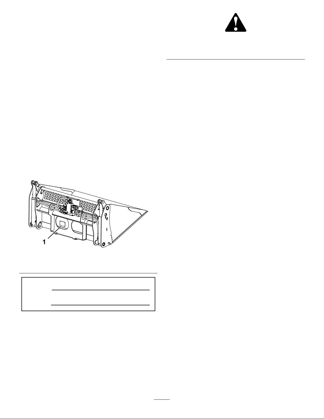
136-5844
decal136-5844
1.Pressthejoystickswitch
lefttoopenthebucket
jaws.
2.Pressthejoystickswitch
righttoclosethebucket
jaws.
3.Locktheaccessoryinto
Forward.
100-4648
1.Warning;crushingofarmhazard;crushingofleg
hazard—keepbystandersawayfromthemachine.
AU117-1898
decal100-4648
decalau117-1898
1.Tippinghazard—readtheOperator’sManual;themaximum
loadis408kg(900lb).
5

Setup
LooseParts
Usethechartbelowtoverifythatallpartshavebeenshipped.
ProcedureDescription
1
2
3
4
5
6
7
Nopartsrequired
Connectormountbracket
7-pinconnector1
Bolt(5/32inches)
Spacer
Nut(5/32inches)
Relayandloaderarmharness1
Plugnut1
Grommet
Wireharnessretainer1
Screw
Self-tappingscrew
Relay2
Fuse(5A)
Nopartsrequired
Nopartsrequired
Nopartsrequired
Qty.
Use
–
1
2
2
2
2
2
1
–
–
–
Preparethemachine.
Installtheconnectorandconnector
mountbracket.
Connecttheloaderarmbranch.
Connecttherelayandpowerlead
connectors.
Removetheexistinglever.
Installthe4-in-1bucketlever.
Installthevalvesolenoidharness.
8
9
Note:Retainallremovedpartsforlaterinstallation
unlessotherwisedirected.
Important:Youmustacquire2screws(5/16–18
TPI1.75inches)tocompletethisinstallation.
Important:Caporpluganydisconnected
hydraulichoses,tubes,orcomponentportsto
preventcontaminationenteringthesystem.
Nopartsrequired
Nopartsrequired
–
–
Testtheinstallation.
Completetheinstallation.
1
PreparingtheMachine
NoPartsRequired
Procedure
1.Installthebucket;refertoyourmachine
Operator’sManualforinformationoninstalling
andremovingthebucket.
Important:Alwaysusethetractionunitto
liftandmovetheattachment.
Important:Beforeinstallingthebucket,
ensurethatthemountplatesarefreeofany
dirtordebrisandthatthepinsrotatefreely.
Ifthepinsdonotrotatefreely,greasethem.
6
2.Parkthemachineonalevelsurface,engagethe
parkingbrakeandlowerthearms.
3.Shutofftheengine,removethekeyandallow
theenginetocool.
4.Turnthebattery-disconnectswitchtotheoff
position;refertoyourmachineOperator’s
Manual.
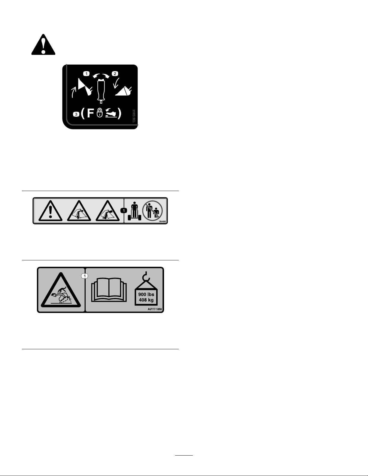
5.Ifyourmachinedoesnothavea
battery-disconnectswitch,disconnectthe
negative(black)cablefromthebattery,then
disconnectthepositive(red)cable(Figure4).
Figure4
2
InstalltheConnectorand ConnectorMountBracket
Partsneededforthisprocedure:
1
Connectormountbracket
17-pinconnector
2
Bolt(5/32inches)
2
Spacer
2
Nut(5/32inches)
Procedure
1.Releaseanybuiltuphydraulicpressureby
movingtheauxiliaryhydraulicsleverforward
andbackwardafewtimes.
g029753
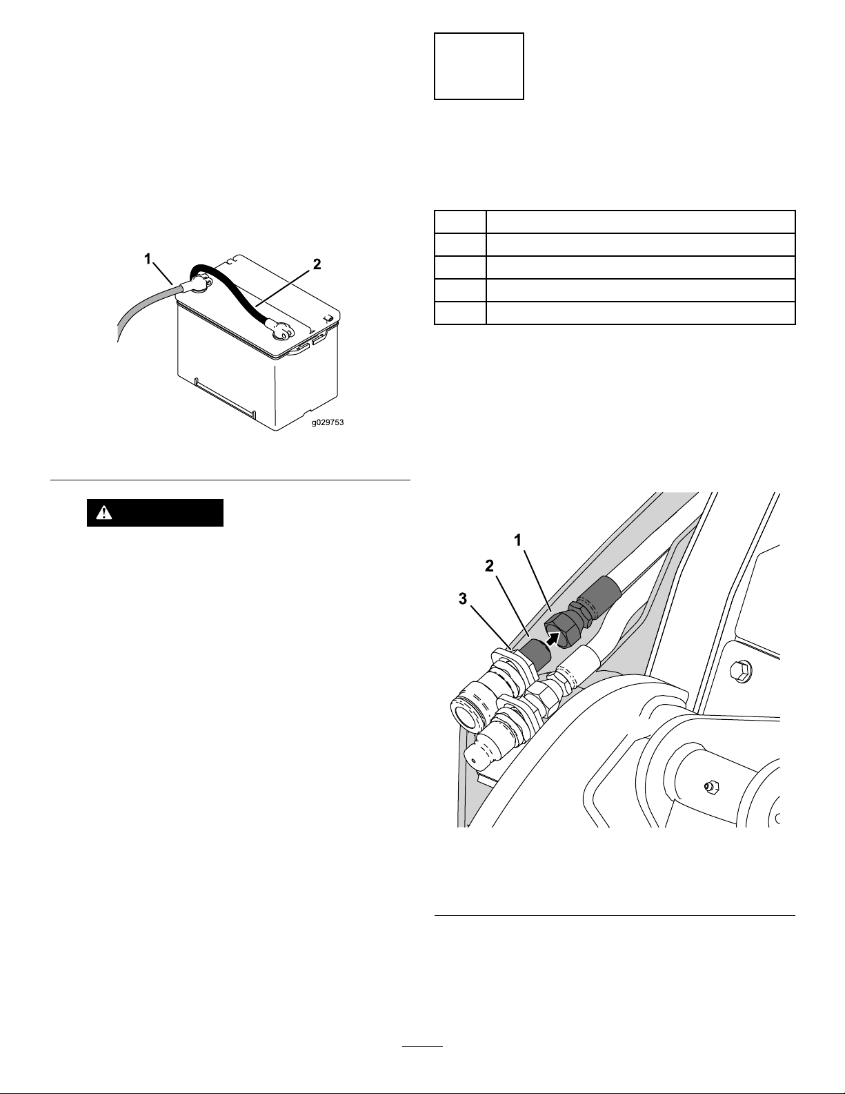
2.Disconnecttherightsideouterhosetting
(1–1/8inches)fromthebulkheadcouplerand
plugthehoseend.
WARNING
Incorrectbatterycableroutingcould
damagethemachineandcables,causing
sparks.Sparkscancausethebattery
gassestoexplode,resultinginpersonal
injury.
•Alwaysdisconnectthenegative
(black)batterycablebefore
disconnectingthepositive(red)
cable.
•Alwaysconnectthepositive(red)
batterycablebeforeconnectingthe
negative(black)cable.
1.Hosetting
2.Bulkheadcouplerthreads
g242258
Figure5
3.Bulkheadcouplerlocknut
3.Removethebulkheadcouplerlocknut(1–5/16
inches).
4.Aligntheconnectormountbracketoverthe
threadedendofthebulkheadcouplerand
secureitwiththebulkheadcouplerlocknut.
7
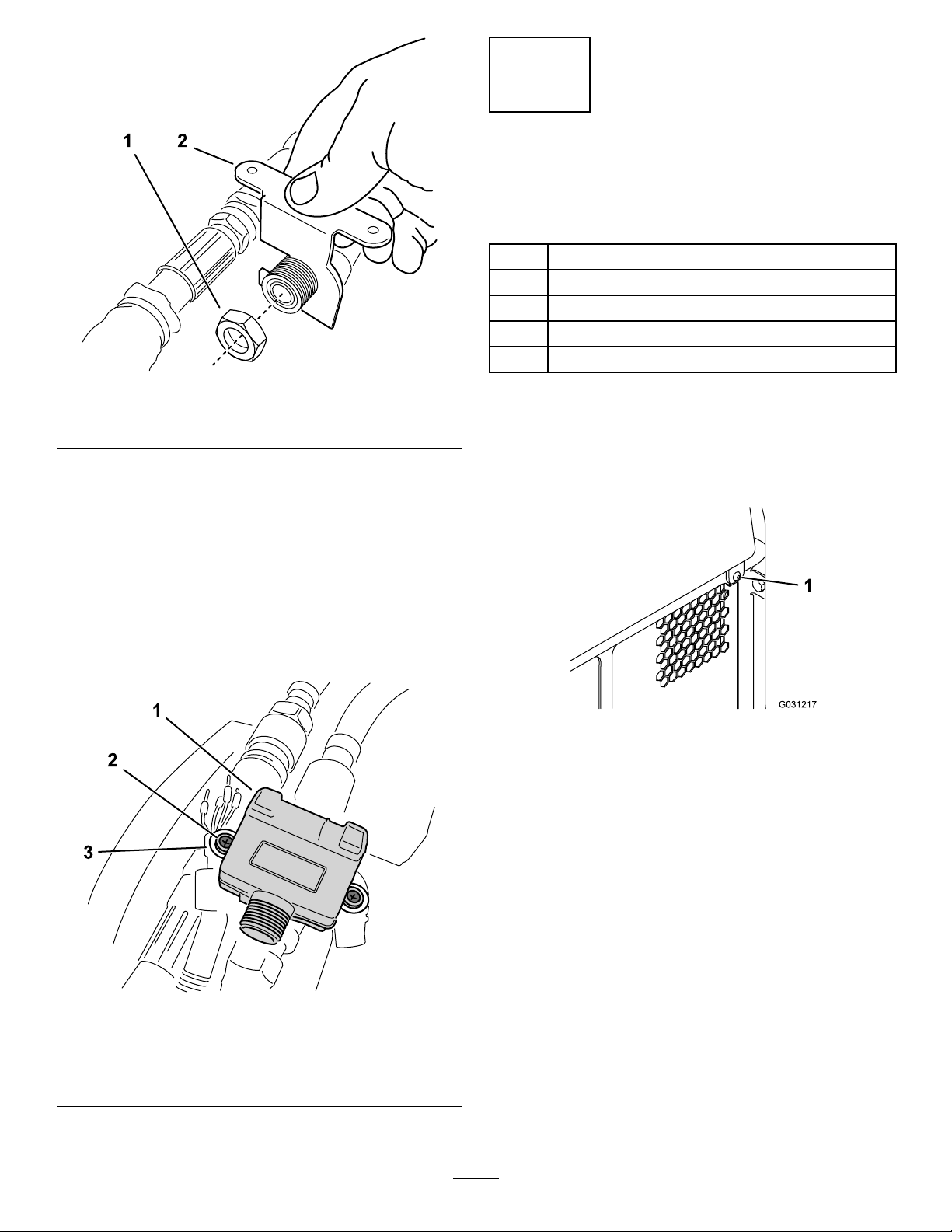
Figure6
3
ConnectingtheLoaderArm Branch
Partsneededforthisprocedure:
1Relayandloaderarmharness
1Plugnut
Grommet
1Wireharnessretainer
2
Screw
g242236
1.Bulkheadcouplerlocknut
5.Removetheplugandconnectthehosetting
removedinstep2.T orquethettingto60to74
ft-lb(81to100N·m).
6.Removethegrommetandplugnutfromtherear
ofthe7-pinconnector,aswellasthepartsbag
insidetheconnector.
7.Installthe7-pinconnectortothetopofthe
connectormountbracketwith2bolts(5/32
inches),washers,andnuts(Figure7).Tighten
thenutssecurely.
2.Connectormountbracket
Procedure
1.Loosenthecaptivescrew(7/16inch)onthe
bottomrightoftherear-accesscoverandopen
it(Figure8).
g031217
Figure8
1.Captivescrew
2.Alongthetoprailoftherightloaderarm,remove
the2screws,hosehold-downplates,and
spacertubes(Figure9).
1.7-pinconnector
2.Bolt(washerandnuton
undersideofbracket)
g242253
Figure7
3.Connectormountbracket
8
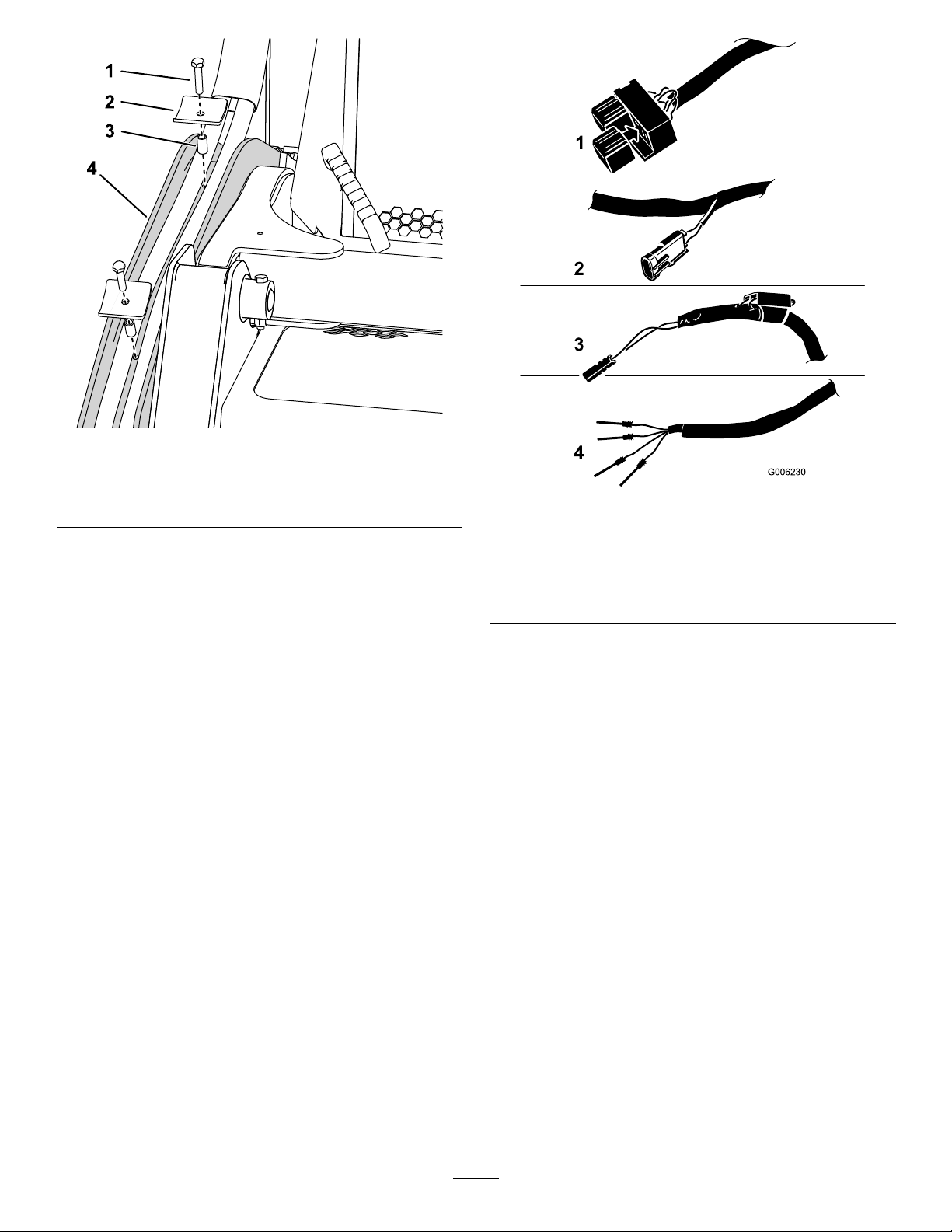
Figure9
g242240
1.Screw3.Spacertube
2.Hosehold-downplate4.Loaderarm
3.Findtheloaderendbranchoftherelayand
loaderarmharness(Figure10).
Figure10
Relayandloaderarmharnessconnections
1.Relaybranch3.Powerleadbranch
2.Loaderarm/attachment
leverconnector
4.Loaderendbranch
g006230
9

4.Routetheloaderendbranchintotherearofthe
machinealongthelowerfrontendoftheloader
armvalveassembly(Figure11)andoutthrough
therighthoseaccess(Figure12).
5.Routetheloaderendbranchupintotheouter
protectivesleeve,thenrouteitalongthebottom
oftheinnerhydraulichosesothatthewires
reachthe7-pinconnector.
6.Installtheplugnut(large)andthenthegrommet
(small,narrowendfacingthe7-pinconnector)
overthewires.
Figure11
1.Loaderendbranch2.Righthoseaccess
g242387
g242237
Figure13
1.Plugnut
2.Grommet
7.Removethetophalfofthe7-pinconnectorand
installthe4loaderendwiresintothecorrect
connectorterminalsinsideasshowninFigure
14.
1.Righthoseaccess
2.Loaderendbranch
g242409
Figure12
3.Outerprotectivesleeve
g242270
Figure14
1.Wireharnessretainer4.Yellow-T erminal2
2.White-T erminal65.Black-T erminal7
3.Black-T erminal5
10

8.Tightentheterminalscrewsandpullonthewires
toensurethattheyaresecurelyconnected.
9.Installthewireharnessretainerand2screws
(Figure14).
10.Installtheconnectortophalfandscrewonthe
plugnutsecurely ,atthesametimeseatingthe
grommet(Figure15).
Figure15
1.Threadtheplugnutonto
the7-pinconnector
2.Connectortophalf
4
ConnectingtheRelayand PowerLeadConnectors
Partsneededforthisprocedure:
2
Self-tappingscrew
2Relay
1
Fuse(5A)
AssemblingtheRelayConnectors
totheMachine
ForModel22327withserialnumbersprior
to316000467andModel22328withserial
g242272
numberspriorto316999999
1.Fromtherearofthemachine,positionthe
relayconnectorsonthelowerrearfaceofthe
auxiliaryvalvebracketandmarkthelocationof
themountingholesonthebracket.
11.Installthehosehold-downplatesandspacer
tubesremovedinstep2.
Important:Ensurethatthewireharnessis
nottootautatthe7-pinconnector;givethe
harnesssufcientslackbeforetightening
thehold-downplates.
12.Replacethepreviouslyremovedscrewswith2
longerscrews(5/16–18TPIx1.75inches).
Note:Thesescrewsarenotsuppliedwiththe
attachment.
g242413
Figure16
1.Auxiliaryvalvebracket3.Relayconnectors
2.Drillahole(4mm)here.4.Self-tappingscrews
2.Drillholes(2)usinga4mmdrillbitatthemarks
madeinstep1.
3.Usingthe2self-tappingscrews,installtherelay
connectorstotheauxiliaryvalvebracket(Figure
16).
11

4.Installthe2relaystothebucketrelayconnectors
andcontinuetoConnectingthePowerLead
Branch(page12).
AssemblingtheRelayConnectors
totheMachine
ForModel22327withserialnumbersafter
316000467andModel22328withserial
numbersafter316999999
1.Fromtherearofthemachine,removeboth
existingrelaysfromtheignitionrelayconnectors
(Figure17).
ConnectingthePowerLead
Branch
1.Withacabletie,securetheharnesstothehose
ttingintheT1portontheleftsideoftheloader
armvalveassembly.
Important:Routethewireharnessaway
fromanyhotormovingparts,securewith
cabletiesasneeded.
2.Openthehood,propitup,andremovetheheat
shield(Figure18).
Figure17
1.Bucketrelayconnectors3.Ignitionrelayconnectors
2.Matingtangs4.Ignitionrelays
2.Loosentheignitionrelayconnectormounting
boltsandnuts.
3.Slidethematingtangsofthebucketrelay
connectorsontothetangsoftheleftignition
relayconnector(Figure17).
4.Tightentheignitionrelayconnectormounting
hardwareandinstalltherelaysremovedinstep
1.
5.Installthe2relaystothebucketrelayconnectors
andcontinuetoConnectingthePowerLead
Branch(page12).
g038212
Figure18
1.Screw(3)
2.Heatshield
3.Feedthepowerleadbranchforwardandaround
thefrontoftheauxiliaryvalve.
g242426
4.Removethecapfromtheplug-and-socket
connectorontheauxiliarylowowharnessand
connectthepowerleadbranchtotheopen
connector(Figure19).
g038242
Figure19
1.Powerleadconnector
2.Auxiliarylowow
connector
5.Installthecapintotheshort,taped-back
connectoronthepowerleadbranch.
Note:Securethewireharnesssothatitdoes
notcontacttheheatshield.
12

6.Installthe5Afuseintotheinlinefuseblockon
thepowerleadbranch.
5
RemovingtheExisting Lever
NoPartsRequired
Procedure
1.Removetheretainingringfromtheloader
arm/attachmenttiltlevershaftandmovethe
washerup(Figure20).
Figure20
2.Pushuptheairdeectorfrombelowthecontrol
panelandslideitupthelever(Figure20).
Note:Y oumayneedtoadjustthepositionof
thelevertoremovetheairdeector.
3.Loosenthelocknut(3/4inch)atthebaseofthe
lever(Figure21).
g242427
Figure22
1.Drilla5mmdiameterhole
fortheleverconnector
wire
2.Cuta30mmslotfromthe
centreofthedrilledhole
3.10mmfromtheedgeof
theexistingholetothe
centreofthenewhole
g242495
4.Existinghole
5.Slotsfacetowardlower
rightsideofcontrolpanel
Figure21
Somepartsnotshownforclarity
4.Unscrewandremovetheleverandairdeector
(Figure21).
5.ModifytheairdeectorasshowninFigure22.
g242496
13

6
Installingthe4-in-1Bucket Lever
NoPartsRequired
Procedure
1.Ensurethattherockerswitchesatthetopof
the4-in-1bucketleverareatrightanglestothe
shaftopeningasshowninFigure23andtighten
thehandlelocknut.
8.Attachthehandleinstructionaldecalontothe
bottomleftcornerofthecontrolpaneldecalas
showninFigure24.
Note:Cleanandpreparethecontrolpanel
decalbeforeinstallingthehandledecal.
2.Removetheinsertlocknut(Figure23)and
puttheleverthroughtheairdeectorwiththe
openingfacingforwardandthelevershaftlead
andconnectorfedthroughthesmalldrilledhole.
3.Installthelocknuttothebottomoftheleverand
threadtheleverintotheloadervalveassembly.
Note:Rotatetheairdeector,lever,andlever
connectorwirealtogethertomaintainthecorrect
orientation.
Figure23
1.Rockerswitch4.Insertlocknut
2.Handlelocknut
3.Shaftopening
5.Levershaftlead
g242493
Figure24
g242494
4.Withtheshaftopeningfacingforward,secure
theleverfromrotationandtightentheinsert
locknut(18mm)securelytotheloadervalve
assembly.
5.Loopthelevershaftleadclockwisearoundthe
topoftheloadervalveassembly.
6.Connecttheleverconnectortotheloader
arm/attachmentleverconnectorbeneaththe
controlpanel(Figure10).
7.Pushtheairdeectorbelowthecontrolpanel
andmovetheleverinalldirectionstoensure
thatitslidesfreely.
14

7
InstallingtheValveManifold SolenoidHarness
NoPartsRequired
Procedure
1.Removethe4boltsandwasherssecuringthe
manifoldcoverfromthe4-in-1bucket(Figure
25).
g242609
Figure26
Figure25
1.Manifoldcover2.Boltandwasher(4)
2.Feedthesolenoidconnectorendofthevalve
manifoldsolenoidharnessdowntheouter
protectivesleeveofthe4-in-1buckethoses.
3.Removetheplugsfromthevalvemanifold
terminalsandinstallthesolenoidconnectorsas
showninFigure26.
1.Valvemanifold3.Valvemanifoldsolenoid
harness
2.Leftandrightsolenoid
connectors
4.Tightenthecentrescrewsonthesolenoid
connectorssecurely.
g242611
15

5.Liftupthespring-loadedcoveronthe7-pin
connectorandinsertthevalvemanifoldsolenoid
harnessconnector(Figure26).
4.Turnthelowowswitchontoactivatethe
auxiliaryhydraulicslowowsystem.
5.Setthethrottletofastandlocktheauxiliary
hydraulicsleverintheforwardowposition;
refertoyourmachineOperator’sManual.
Important:Operatethebucketjawsonly
withtheauxiliaryhydraulicsleverinthe
forwardowposition.
6.Operatetheleftandrightsidesoftherocker
switchontopofthe4-in-1bucketlever;the
bucketshouldopenandcloseandagreen
LEDwithineachofthevalvemanifoldsolenoid
harnessconnectorsshouldilluminate.
Note:Whentheleftsideoftherockerswitchis
depressedthejawsshouldopen,whentheright
sideispressedthejawsshouldclose.Ifthejaws
open/closeinreverse,loosenthehandlelocknut
(Figure23)andscrewthehandledown180°.
Securethehandleandtightenthelocknut.
Figure27
1.7-pinconnector3.Lockingtang
2.Spring-loadedcover4.Valvemanifoldsolenoid
harnessconnector
Note:Ensurethatthecoverisfullyclosedover
thelockingtangsonthevalvemanifoldsolenoid
harnessconnector.
8
TestingtheInstallation
NoPartsRequired
Procedure
1.Turnthebattery-disconnectswitchtotheON
position;refertoyourmachineOperator’s
Manual.
g242610
7.Movetheauxiliaryhydraulicslevertotheneutral
position.
8.Raisetheloaderarmtothehalfwayposition
andfullytiltthebucketforward.
9.Ensurethatthereisnotensiononthevalve
manifoldsolenoidharnessattheconnectionto
theloaderarmharness.
10.Fullydumpandcurlthebucket;atthemidpoint
ofthismotionensurethatthehosesdonotbend
excessivelyattheirconnectionstothemanifold
assembly.
Important:Ifthereisexcessivebendingin
thehoses,youmustloosenandadjustthe
portttingstocorrecttheangle;excessive
bendingofthehosescausesstressand
damagetothehosesandttings.
2.Ifyourmachinedoesnothavea
battery-disconnectswitch,connectthe
positive(red)cabletothepositive(+)terminal
andthenegative(black)cabletothenegative(-)
terminalofthebattery(Figure4).
Note:Securethecablesusingthecable
mountinghardwareusedpreviously.
3.Starttheengineandraisetheloaderarmsothe
bucketisofftheground.
16

9
CompletingtheInstallation
NoPartsRequired
Procedure
1.Tiltthe4-in-1bucketbackandlowertheloader
arm.
2.Shutofftheengineandremovethekey.
3.Checkallhydraulicconnectionsforleaksand
correctasnecessary.
4.Checkthehydraulicuidlevelandcorrectas
necessary;refertoyourmachineOperator’s
Manual.
5.InstalltheheatshieldasshowninFigure18.
6.Closeandsecuretheenginehood.
7.Installthevalvemanifoldcovertothe4-in-1
bucketandsecureitwiththe4boltsand
washersasshowninFigure24.
ProductOverview
g242329
Figure28
1.4-in-1bucket3.Hydraulicandelectrical
connections
2.Manifoldcover4.Loaderarm/attachmenttilt
lever
Important:The4-in-1bucketmustnot
beusedwithoutthevalvemanifoldcover
installed.Thewarrantyonthevalvemanifold
assemblywillbevoidedifthecoverisnot
installedorinstalledincorrectly.
Controls
Becomefamiliarwithallthecontrols(Figure29and
Figure30)beforeyoustarttheengineandoperate
thetractionunit.
AuxiliaryHydraulicsLowFlow
Switch
Pressonthefrontoftheauxiliaryhydraulicslowow
switchtoturniton.
17
g239507
Figure29
1.Lowowswitch

LoaderArm/AttachmentTiltLever
Specications
Usetheloaderarm/attachmenttiltlevertooperatethe
4-in-1bucket(Figure30).
Important:Forthebucketjawstooperate,you
musthavetheauxiliaryhydraulicsleverinthe
forwarddetentposition.
Figure30
1.Lowertheloaderarms
2.Raisetheloaderarms
3.Tiltthebucketrearward
4.Tiltthebucketforward
5.Open/closethebucket
jaws
Note:Specicationsanddesignaresubjectto
changewithoutnotice.
4-in-1ExtraHighVolumeBucket
ModelBU003915
1346mm Width
(53inches)
804mm Length
(31.7inches)
Height
Weight
Capacity(SAEstruck
capacity)
Maximumdensity ,heaped
Maximumdensity ,struck
g242271
4-in-1WideBucket
ModelBU003895
Length
Height
Weight
Capacity(SAEstruck
capacity)
Maximumdensity ,heaped
Maximumdensity ,struck
558mm(22inches)
212kg(467.4lbs)
3
0.22m
(7.8ft
2151kg/m
(134.3lb/ft
2558kg/m
(159.7lb/ft
1067mm Width
(42inches)
685mm(27inches)
558mm(22inches)
166kg(365lbs)
3
0.15m
(5.3ft3)
1796kg/m
(112.1lb/ft
2156kg/m
(134.6lb/ft
3
)
3
3
)
3
3
)
3
3
)
3
3
)
4-in-1NarrowBucket
ModelBU004001
Width
Length
Height
Weight
Capacity(SAEstruck
capacity)
Maximumdensity ,heaped
Maximumdensity ,struck
18
863mm(34inches)
685mm(27inches)
558mm(22inches)
145kg(319.7lbs)
3
0.12m
(4.3ft3)
1004kg/m
(66.7lb/ft
1221kg/m
(76.2lb/ft
3
3
)
3
3
)

MaximumMaterialDensityat Capacity
Thedensityofthematerialsmovedbythebucket
variesand,therefore,sodoestheamountofmaterial
thatthebucketcancarrybeforereachingthe
maximumloadrating.ThetablesinSpecications
(page18)listthedensityofmaterialthatcanbe
carried,bothheapedandstruck(i.e.,leveledoff),in
thebucket.Thetablebelowlistscommonmaterials
andtheirdensities.
Tomovethematerialswithdensitiesgreaterthanthe
maximumallowedforthebucket,reducethevolume
ofthematerialplacedinthebucket.
MaterialDensity
Material
Caliche1250kg/m
Clay:
Naturalbed
Dry
Wet
Withgravel,dry
Withgravel,wet
Coal:
Anthracite,broken
Bituminous,broken
Earth:
Dry,packed
Wet,packed
Loam
Granite,brokenorlarge
crushed
Gravel:
Dry
Pitrun(graveledsand)
Dry,13to51
mm(1/2to2inch)
Wet,13to51mm(1/2
to2inch)
Limestone,brokenorcrushed
Sand:
Dry
Wet
Withgravel,dry
Withgravel,wet
Sandstone,broken1510kg/m
Shale1250kg/m
Slag,broken1750kg/m
Stone,crushed1600kg/m
Topsoil
Density(Approximate)
3
(78lb/ft
1600kg/m
1480kg/m
1660kg/m
1420kg/m
1540kg/m
1100kg/m
830kg/m
1510kg/m
1600kg/m
1250kg/m
1660kg/m
1510kg/m
1930kg/m
1690kg/m
2020kg/m
1540kg/m
1420kg/m
1840kg/m
1720kg/m
2020kg/m
950kg/m
3
3
3
3
3
(96lb/ft
3
3
(52lb/ft
3
3
3
(78lb/ft
3
(104lb/ft
3
3
3
3
(126lb/ft
3
(96lb/ft
3
3
3
3
(126lb/ft
3
(94lb/ft
3
(78lb/ft
3
(109lb/ft
3
(100lb/ft
3
(59lb/ft
3
)
(104lb/ft
(93lb/ft
(104lb/ft
(89lb/ft
(69lb/ft
(94lb/ft
(100lb/ft
(94lb/ft
(120lb/ft
(106lb/ft
(89lb/ft
(115lb/ft
(107lb/ft
3
)
3
)
3
)
3
)
3
)
3
)
3
)
3
)
3
)
3
)
3
)
3
)
3
)
3
)
3
)
3
)
3
)
3
)
3
)
3
)
3
)
3
)
3
)
3
)
3
)
19

Operation
The4-in-1bucketcanbeusedin4differentoperating
modes:
•Bucket
•Blade
CAUTION
Hydrauliccouplers,hydrauliclines/valves,
andhydraulicuidmaybehot.Ifyoucontact
hotcomponents,youmaybeburned.
•Weargloveswhenoperatingthehydraulic
couplers.
•Leveller
•Grapplebucket
InstallingandRemoving theAttachment
RefertotheOperator’sManualforthetractionunitfor
theinstallationandremovalprocedure.
Important:Beforeinstallingtheattachment,
positionthemachineonalevelsurface,ensure
thatthemountplatesarefreeofanydirtordebris,
andensurethatthepinsrotatefreely .Ifthepins
donotrotatefreely,greasethem.
Note:Alwaysusethetractionunittoliftandmove
theattachment.
WARNING
Ifyoudonotfullyseatthequick-attach
pinsthroughtheattachmentmountplate,
theattachmentcouldfalloffthemachine,
crushingyouorbystanders.
Ensurethatthequick-attachpinsarefully
seatedintheattachmentmountplate.
•Allowthemachinetocoolbeforetouching
hydrauliccomponents.
•Donottouchhydraulicuidspills.
4-in-1Operationand Control
Afteryouattachthe4-in-1buckettothemountplate
ofthetractionunit,ensurethatthehydrauliccouplers
areconnected,andthattheauxiliaryhydraulicslow
owsystemisturnedon.Startandrunthemachineat
fullthrottle.
Whenloadingmaterial,alwayshavethebucketlevel
tothegroundandmoveforwardintothematerialto
belifted.Whenthebucketisfull,tiltitrearwardto
decreasetheliftingresistancewhenyoulifttheload.
TransportPosition
Whentransportingaload,keeptheattachmentas
closetothegroundaspossible,nomorethan6
inchesabovethelowestposition.Tiltitrearwardto
keeptheloadlevel.
WARNING
Hydraulicuidescapingunderpressurecan
penetrateskinandcauseinjury.Fluidinjected
intotheskinmustbesurgicallyremoved
withinafewhoursbyadoctorfamiliarwith
thisformofinjury;otherwise,gangrenemay
result.
•Ensurethatallhydraulic-uidhoses
andlinesareingoodconditionandall
hydraulicconnectionsandttingsaretight
beforeapplyingpressuretothehydraulic
system.
•Keepyourbodyandhandsawayfrom
pinholeleaksornozzlesthateject
high-pressurehydraulicuid.
•Usecardboardorpapertondhydraulic
leaks;neveruseyourhands.
1.Nomorethan6inches
20
g240205
Figure31
2.Tilttheloadrearward
abovethelowestposition

BucketOperation
Youcandrawthejawstogethertousethisattachment
asastandardbucket.Youcanalsoopenthe4-in-1
bucketjawstodumpthecontentsintoahigherarea
thanastandardbucketcanreach.
Whenloadingmaterial,alwayshavethebucketlevel
tothegroundandmoveforwardintothematerialto
belifted.Whenthebucketisfull,tiltitrearwardto
decreasetheliftingresistancewhenyoulifttheload.
Whentransportingaload,keepthebucketasclose
tothegroundaspossible.
BladeOperation
Withthejawscompletelyopen,youcanusetheback
ofthebucketasabladetopushmaterial.Y oucan
alsopartiallyclosethejawsandusingthebottomof
thefrontbuckettoknockthetopofclumpsandgrade
withtherearblade.
Whenscraping,levellingandsurfacestripping,lower
thebladetotheground,ensuringthatthecuttingedge
makescontact.Thebladewillbiteintothesoilasyou
moveforward.
g235997
Figure32
Correctoperation
Important:Donotusetheoortopickorpull
objects.Thiswillcausedamagetotheoor/
bucketandwillvoidthebucketwarranty(Figure
33).
LevellerOperation
Withthejawsfullyopenandthebuckettippedslightly
forwardsothatthebackcuttingedgeoftheoorison
theground,andthefrontedgeisofftheground.The
angleofthebackcuttingedgeyoucanusethebucket
asalevellerbymovingthecuttingedgebackacross
thesurfaceoftheground.
GrappleBucketOperation
Thesidejawscanalsobeusedforpickingupmaterial
byclosingthemoverobjectsormaterialstobe
transported(Figure32).
Note:T akecarewhenusingthismethodthatyou
don’tcrushanobjectthatyouarepickingupbetween
thesidejaws.
g235998
Figure33
Incorrectoperation
21

Maintenance
RecommendedMaintenanceSchedule(s)
MaintenanceService
Interval
Beforeeachuseordaily
Every200hours
Beforestorage
MaintenanceProcedure
•Lubricatethebucket
•Ensurethatallfastenersaresecurelytightened.
•Inspectthehydraulicsystemforleaksandloosettings.
•Cleantheareasaroundthebucketcylinderandmountplatepivot.
•Checkforwearofpins,linkages,andcuttingedges.
•Greasethebucketpivotpoints.
•Ensurethattherelayandloader-endharnessandvalvemanifoldsolenoidharness
aresecure.
•Lubricatethebucket
•Inspectthehydraulicsystemforleaksandloosettings.
•Inspectthehydraulicsystemforleaksandloosettings.
LubricatingtheBucket
ServiceInterval:Beforeeachuseordaily
Every200hours
Usingagreasegun,pumpgeneralpurposegrease
intothesixgreasettingsonthe4-in-1bucketuntil
thegreasebeginstoooze(Figure34).Wipeaway
anyexcessgreasewithashopcloth.
Adjustingthe4-in-1Bucket Operation
Thespeedcontrolonthevalvemanifoldcanbeused
toadjusttheopeningandclosingspeedofthe4-in-1
bucketjaws.
1.Starttheengineandraisetheloaderarmsothat
the4-in-1bucketisclearoftheground.
1.Greasettings
2.Removethe4boltsandwasherssecuringthe
valvemanifoldcovertothe4-in-1bucketand
removethecover(Figure25).
3.Movetheauxiliaryhydraulicsleverfromthe
neutraltoforwardowdirectionacoupleof
timestorelieveanyhydraulicsystempressure
inthevalvemanifold.
Note:Ifthereishydraulicpressureactingin
thevalvemanifoldthecontrolknobcannotbe
moved.
4.Loosenthespeedcontrollockingnut(turning
itcounterclockwise)toallowtheadjustmentof
speedcontrolknob(Figure35).
g006224
Figure34
22

Figure35
Somepartsnotshownforclarity
1.Valvemanifold3.Speedcontrolknob
2.Speedcontrollockingnut
5.Adjustthespeedcontrolknob:
Storage
1.Beforelong-termstorage,washtheattachment
withmilddetergentandwatertoremovedirtand
grime.
2.Checkandtightenallbolts,nutsandscrews.
Repairorreplaceanypartthatisdamagedor
worn.
3.Ensurethatallthehydraulichosecouplersare
connectedtogethertopreventcontamination
enteringthehydraulicsystem.
4.Paintallscratchedorbaremetalsurfaces.
Note:PaintisavailablefromyourAuthorized
ServiceDealer.
g242385
5.Greasethepivotpoints;refertoLubricatingthe
Bucket(page22).
6.Storetheattachmentinaclean,drygarageor
storagearea.
7.Coverthebuckettoprotectitandkeepitclean.
•Toincreasetheopening/closingspeedofthe
bucket,turntheknobclockwise.
•Todecreasetheopening/closingspeedof
thebucket,turntheknobcounterclockwise.
6.Movetheauxiliaryhydraulicsleverfromthe
neutraltoforwarddirectionacoupleoftimes
torelieveanyhydraulicsystempressureinthe
valvemanifold.
7.Turnthespeedcontrollockingnutclockwiseto
securethesetting.
8.Installthevalvemanifoldcovertothe4-in-1
bucketandsecureitwiththe4boltsandwashers
removedinstep2.Tightentheboltssecurely.
Important:The4-in-1Bucketmustnot
beusedwithoutthevalvemanifoldcover
installedandsecuredinplace.Thewarranty
onthevalvemanifoldassemblywillbe
voidedifthecoverisnotinstalled,or
incorrectlyinstalled.
23

Troubleshooting
Problem
Bucketdoesnotopenorclose.
PossibleCauseCorrectiveAction
1.Electricalcircuitissue.1.Inspectthewireharnessandelectrical
2.Thefuse(s)areblown.2.Replaceanyblownfuses.
3.Thereareloosepowerorearth
connection(s).
4.Therearedisconnectedwire(s)at
systemterminal(s).
5.Thereareopenorshortcircuit(s)inthe
wire(s).
6.Thewireharnessrelay(s)arenot
functioningcorrectly.
7.Theloaderarm/attachmenttiltlever
contactsarenotfunctioningcorrectly .
8.Thevalvemanifoldsolenoid(s)are
notfunctioningcorrectly(Resistance
acrosssolenoidterminalsshouldbe
approximately6.5ohms).
9.Thehydrauliccoupler(s)arenot
completelyconnected.
10.Thereismoisturebetweenthevalve
solenoidcoilsandthevalvesolenoid
shaft.
11.Thevalvemanifoldand/oraninternal
valveisnotoperatingcorrectly.
12.Thereisanobstructioninahydraulic
hose.
13.Theauxiliaryvalveonthetractionunit
isnotoperatingcorrectly .
14.The4-in-1buckethydrauliccylinder(s)
arenotoperatingcorrectly.
connections.Refertothewiring
diagram.
3.Ensurethatallwireconnectionsare
correctlyconnectedandsecure.
4.Ensurethatallwireconnectionsare
correctlyconnectedandsecure.
5.Replaceanynon-operationalwire
harness(es).
6.Replaceanynon-operationalrelay(s).
7.Repairorreplacetheloader
arm/attachmenttiltlever.
8.Replaceanynon-operationalvalve
manifoldsolenoids.
9.Ensurethatthecouplersarecorrectly
connectedandsecured.
10.Removethenutsecuringthevalve
solenoidcoilstothesolenoidshaft.
Pullthecoilsfromtheshaftandclean
them;ensurethatthereisnomoisture
betweenthecomponents.Install
thecomponentsandtightenthenut
securely.
11.Repairorreplacethenon-operational
component.
12.Findandremovetheobstruction.
13.Repairorreplacethevalve.
14.Repairorreplaceanynon-operational
hydrauliccylinder(s).
24

Schematics
(Rev.A)
g239505
25

Notes:

Notes:

TheToroWarranty
4in1bucket
Conditions
TheT oro®Companyanditsafliate,T oroWarrantyCompany ,pursuanttoanagreementbetweenthem,jointlywarrantyourT oroProduct(“Product”)
tobefreefromdefectsinmaterialsorworkmanship.
ThewarrantyappliesfromthedateoftheProductisdeliveredtotheoriginalretailpurchaser:
Whereawarrantableconditionexists,wewillrepairtheProductatnocosttoyouincludingdiagnosis,labourandparts.
ProductsWarrantyPeriod
Bucket12months
Wireharnessandvalvemanifold
6months
InstructionsforObtainingWarrantyService
IfyouthinkthatyourT oroProductcontainsadefectinmaterialsorworkmanship,followthisprocedure:
1.ContactanyAuthorisedT oroServiceDealertoarrangeserviceattheirdealership.T olocateaConstructiondealerconvenienttoyou,accessour
websiteatwww.T oro.com.au.
2.Bringtheproductandyourproofofpurchase(salesreceipt)andanexplanationofthefaulttotheServiceDealer .Allcostsassociatedwiththe
returnoftheproductarethepurchaser’sresponsibility.
3.If,foranyreason,youaredissatisedwiththeServiceDealer’sanalysisorwiththeassistanceprovided,contactusat:
CustomerServiceDepartment
ToroAustraliaPtyLtd
Unit1,13DownardStreet
Braeside,Victoria3195
Ph:(03)95807355
OwnerResponsibilities
YoumustmaintainyourToroProductbyfollowingthemaintenanceproceduresdescribedintheOperator’sManual.Suchroutinemaintenance,
whetherperformedbyadealerorbyyou,isatyourexpense.Partsscheduledforreplacementasrequiredmaintenance(“MaintenanceParts”),are
warrantedfortheperiodoftimeuptothescheduledreplacementtimeforthatpart.Failuretoperformrequiredmaintenanceandadjustmentscanbe
groundsfordisallowingawarrantyclaim.
ItemsandConditionsNotCovered
Notallproductfailuresormalfunctionsthatoccurduringthewarrantyperiodaredefectsinmaterialsorworkmanship.Thisexpresswarrantydoes
notcoverthefollowing:
•Productfailureswhichresultintheuseofnon-Tororeplacementparts,orfrominstallationanduseofadd-on,modied,orunapprovedaccessories
•Productfailureswhichresultfromfailuretoperformrequiredmaintenanceand/oradjustments
•Productfailureswhichresultfromoperatingtheproductinanabusive,negligentorrecklessmanner
•Partssubjecttoconsumptionthroughuseunlessfoundtobedefective.Examplesofpartswhichareconsumed,orusedup,duringnormalProduct
operationinclude,butarenotlimitedto,diggingteeth,tines,sparkplugs(petrolmodels),tracks,lters,chains,etc.
•Failurescausedbyoutsideinuence.Itemsconsideredtobeoutsideinuenceinclude,butarenotlimitedto,weather,storagepractices,
contamination,useofunapprovedcoolants,lubricants,additives,orchemicals,etc.
•Normal“wearandtear”items.Normal“wearandtear”includes,butisnotlimitedto,wornpaintedsurfaces,scratcheddecalsorwindows,etc.
•Anycomponentcoveredbyaseparatedmanufacturer’swarranty
•Pickupanddeliverycharges
GeneralConditions
Thepurchaseriscoveredbythenationallawsofeachcountry .Therightstowhichthepurchaserisentitledwiththesupportoftheselawsarenot
restrictedbythewarrantyandthebenetsprovidedunderthiswarrantyareinadditiontoanyrightsandremediesunderanyapplicablelaws..
AllrepairscoveredbythesewarrantiesmustbeperformedbyanAuthorizedT oroServiceDealerusingT oroapprovedreplacementparts.Repairbyan
AuthorizedT oroServiceDealerisyoursoleremedyunderthiswarranty.
Totheextentpermittedbylaw,neitherTheT oroCompanynorToroWarrantyCompanyisliableforindirect,incidental,orconsequential
damagesinconnectionwiththeuseoftheToroProductscoveredbythesewarranties,includinganycostorexpenseofprovidingsubstitute
equipmentorserviceduringreasonableperiodsofmalfunctionornon-usependingcompletionofrepairsunderthesewarranties.
AustralianConsumerLaw:
Australiancustomerswhoareconsidered”consumers”forthepurposesoftheAustralianConsumerLaw:Ourgoodscomewithguaranteesthat
cannotbeexcludedundertheAustralianConsumerLaw.Y ouareentitledtoareplacementorrefundforamajorfailureandcompensationforany
otherreasonablyforeseeablelossordamage.Y ouarealsoentitledtohavethegoodsrepairedorreplacedifthegoodsfailtobeofacceptable
qualityandthefailuredoesnotamounttoamajorfailure.
374-0327RevA
 Loading...