

Page 1

Form No. 3329–316
36 Tiller
XT Series Garden Tractor Attachment
Model No. 79484—230000001 and Up
Operator ’s Manual
English(En)
Page 2
Contents
Introduction 2. . . . . . . . . . . . . . . . . . . . . . . . . . . . . . . .
Safety 3. . . . . . . . . . . . . . . . . . . . . . . . . . . . . . . . . . . . .
Safety and Instruction Decals 3. . . . . . . . . . . . . . .
Assembly 4. . . . . . . . . . . . . . . . . . . . . . . . . . . . . . . . . .
Loose Parts 4. . . . . . . . . . . . . . . . . . . . . . . . . . . . . .
Installing the Tiller Hitch 5. . . . . . . . . . . . . . . . . . .
Installing the Drive Pulley 6. . . . . . . . . . . . . . . . . .
Installing the Idler Pulley and Belt Guide 7. . . . . .
Installing the Rear Shield 7. . . . . . . . . . . . . . . . . . .
Installing the Lift Chain 7. . . . . . . . . . . . . . . . . . . .
Installing the Lift Rod to the Tractor 8. . . . . . . . . .
Installing the Lift Rod to the Tiller 9. . . . . . . . . . .
Installing the Jackshaft 9. . . . . . . . . . . . . . . . . . . . .
Installing the Tiller to the Tractor 10. . . . . . . . . . . .
Removing the Tiller from the Tractor 12. . . . . . . . .
Operation 13. . . . . . . . . . . . . . . . . . . . . . . . . . . . . . . . . .
Operating the Power Take Off (PTO) 13. . . . . . . . .
Using the Attachment Power Lift 13. . . . . . . . . . . .
Operating the Attachment Lift Lever 14. . . . . . . . .
Adjusting the Lift Chain 14. . . . . . . . . . . . . . . . . . .
Tips for Tilling 15. . . . . . . . . . . . . . . . . . . . . . . . . . .
Maintenance 16. . . . . . . . . . . . . . . . . . . . . . . . . . . . . . . .
Recommended Maintenance Schedule 16. . . . . . . .
Greasing and Lubrication 16. . . . . . . . . . . . . . . . . . .
Greasing the Tiller 17. . . . . . . . . . . . . . . . . . . . . . . .
Storage 18. . . . . . . . . . . . . . . . . . . . . . . . . . . . . . . . .
The Toro Total Coverage Guarantee 20. . . . . . . . . . . . .
Page
1
2276
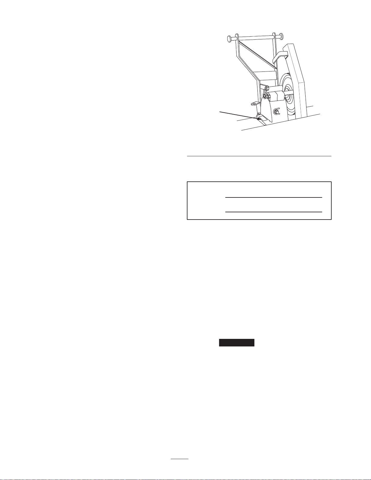
Figure 1
1. Location o f the model and serial numbers
Write the product model and serial numbers in the space
below:
Model No.
Serial No.
This manual identifies potential hazards and has special
safety messages that help you and others avoid personal
injury and even death. Danger, Warning, and Caution are
signal words used to identify the level of hazard.
However, regardless of the hazard, be extremely careful.
Danger signals an extreme hazard that will cause serious
injury or death if you do not follow the recommended
precautions.
Introduction
Read this manual carefully to learn how to operate and
maintain your product properly. The information in this
manual can help you and others avoid injury and product
damage. Although Toro designs and produces safe
products, you are responsible for operating the product
properly and safely.
Whenever you need service, genuine Toro parts, or
additional information, contact an Authorized Service
Dealer or Toro Customer Service and have the model and
serial numbers of your product ready. Figure 1 illustrates
the location of the model and serial numbers on the
product.
2003 by The Toro Company
8111 Lyndale Avenue South
Bloomington, MN 55420-1196
Warning signals a hazard that may cause serious injury or
death if you do not follow the recommended precautions.
Caution signals a hazard that may cause minor or
moderate injury if you do not follow the recommended
precautions.
This manual uses two other words to highlight
information. Important calls attention to special
mechanical information and Note: emphasizes general
information worthy of special attention.
All Rights Reserved
Printed in the USA
2
Page 3
Safety
Warning
Warning
Rotating tines can cut hands, feet or other body
parts.
• Keep away from the rotating tines while
operating the tiller.
• Keep your hands, feet, and any other part of
your body or clothing away from rotating
parts.
• Before adjusting, cleaning, repairing and
inspecting the tiller, lower the tiller and loader
arms to the ground and turn off the engine.
Remove the key.
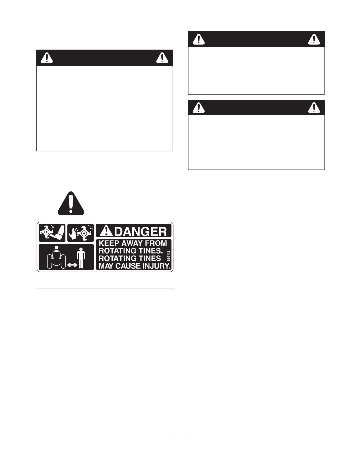
Safety and Instruction Decals
Safety decals and instructions are easily visible to the operator and are located near any
area of potential danger. Replace any decal that is damaged or lost.
Contact with buried power, gas, and/or telephone
lines, in the tilling area, can cause shock or
explosion.
• Have the property or area to be tilled marked
for buried lines.
Warning
Stones and other foreign objects can be picked up
and thrown. This can cause serious personal
injury to operator or bystanders.
• Run the tiller so that debris is thrown away
from the traction unit.
• Keep all bystanders away from the work area.
92-7112
3
Page 4

Assembly
Note: Determine the left and right sides of the machine from the normal operating position.
Loose Parts
Note: Use the chart below to verify all parts have been shipped
DESCRIPTION QTY. USE
Hitch
Spring bracket
Pulley
Key
Set screw 15/16 inch
Idler pulley
Spacer
Belt guide
Belt guard
Bolt 3/8 x 2-1/4 inch
Lock nut 3/8 inch
Rear shield
Cotter pin 1 inch
Lift chain
Clevis
Clevis Pin
Cotter pin 3/4 inch
Lift rod
Washer 3/8 inch
Cotter pin 3/4 inch
Bolt 3/8 x 2–3/4 inch
Spacer .62 O.D x .60 Thk.
1
1
1
1
2
1
1
1
1
1
1
1
3
1
1
1
1
1
2
1
1
1
Installing the tiller hitch
Installing the drive pulley
Installing the idler pulley and belt guard
Installing the rear shield
Installing the lift chain
Installing the lift rod to tractor
Adjustable yoke
Nut 5/16 inch
Clevis
Clevis pin
Cotter pin 3/4 inch
Jackshaft
Extension spring
1
1
1
1
1
1
1
4
Installing the lift rod to tiller
Installing the jackshaft
Page 5
DESCRIPTION USEQTY.
Bolt 3/8 x 1-1/2 inch
Spacer.62 O.D x .60 Thk.
Washer 3/8 inch
Lock nut 3/8 inch
Spring catch
Lift assist spring
Eye bolt
Lock nut 3/8 inch
Belt
Belt
1
1
1
1
1
1
Installing the tiller to the tractor
1
1
1
1
Operator’s Manual 1 Read before installing and operating tiller.
Important A Front Pulley Box/PTO belt and Rear
Attach–A–Matic are required to install and operate the
tiller. If these kits are not already on the tractor, install
them per the instructions included with the kits.
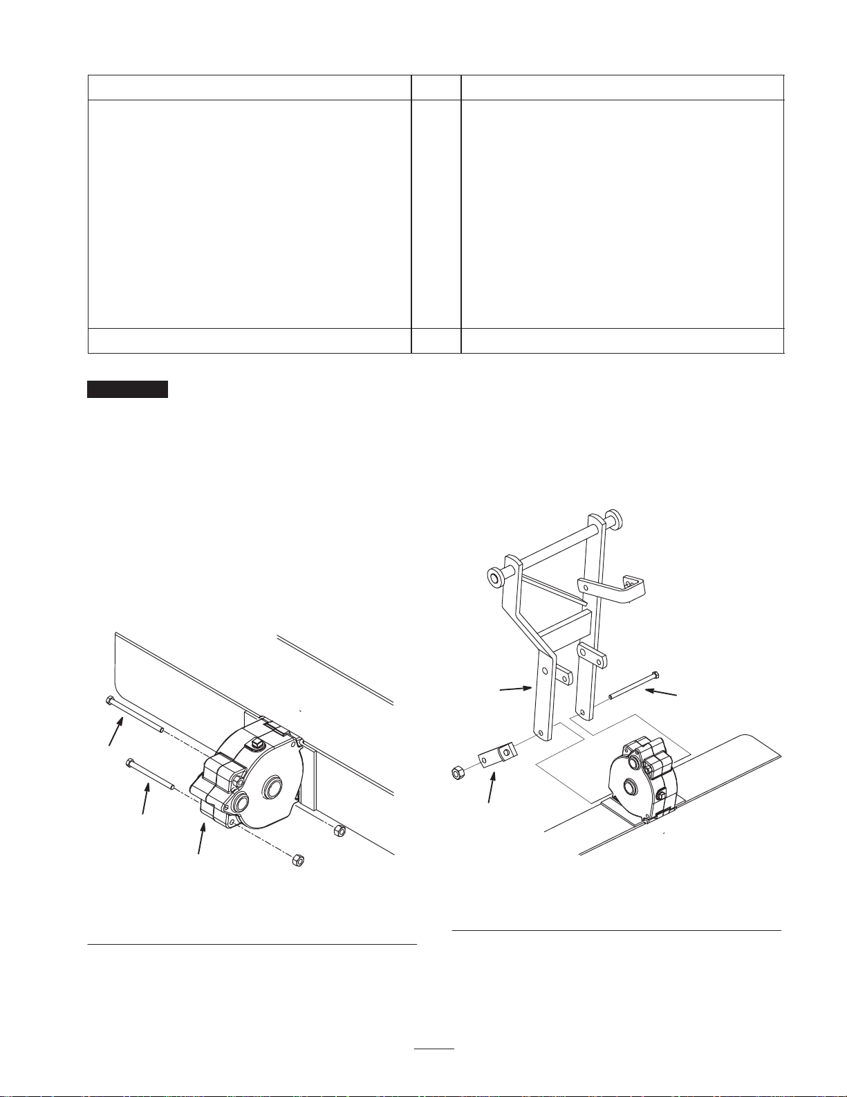
2. Loosely mount the rear of the hitch and the spring
bracket to the rear of the gear case with the previously
removed 3/8 x 5-1/2 inch bolt and nut. Position
components as shown in figure 3. Tighten the bolts
securely.
If you do have these kits, they can be obtained from your
Authorized Service Dealer.
Note: Make sure the bolt is positioned as shown in
figure 3.
Installing the Tiller Hitch
1. Tip the tiller onto its back and support it in an upright
position. Remove the 3/8 x 5-1/2 inch and 3/8 x 4-1/2
inch bolts and the 3/8 inch nuts securing the gear case
together (Fig. 2). Discard extra nuts used as spacers for
shipping.
2
3
1
Figure 2
1. Gear case
2. Bolt, 3/8 x 5–1/2 inch
3. Bolt, 3/8 x 4–1/2 inch
1
2
1. Hitch
2. Spring bracket
3
Figure 3
3. Bolt, 3/8 x 5–1/2 inch
5
Page 6
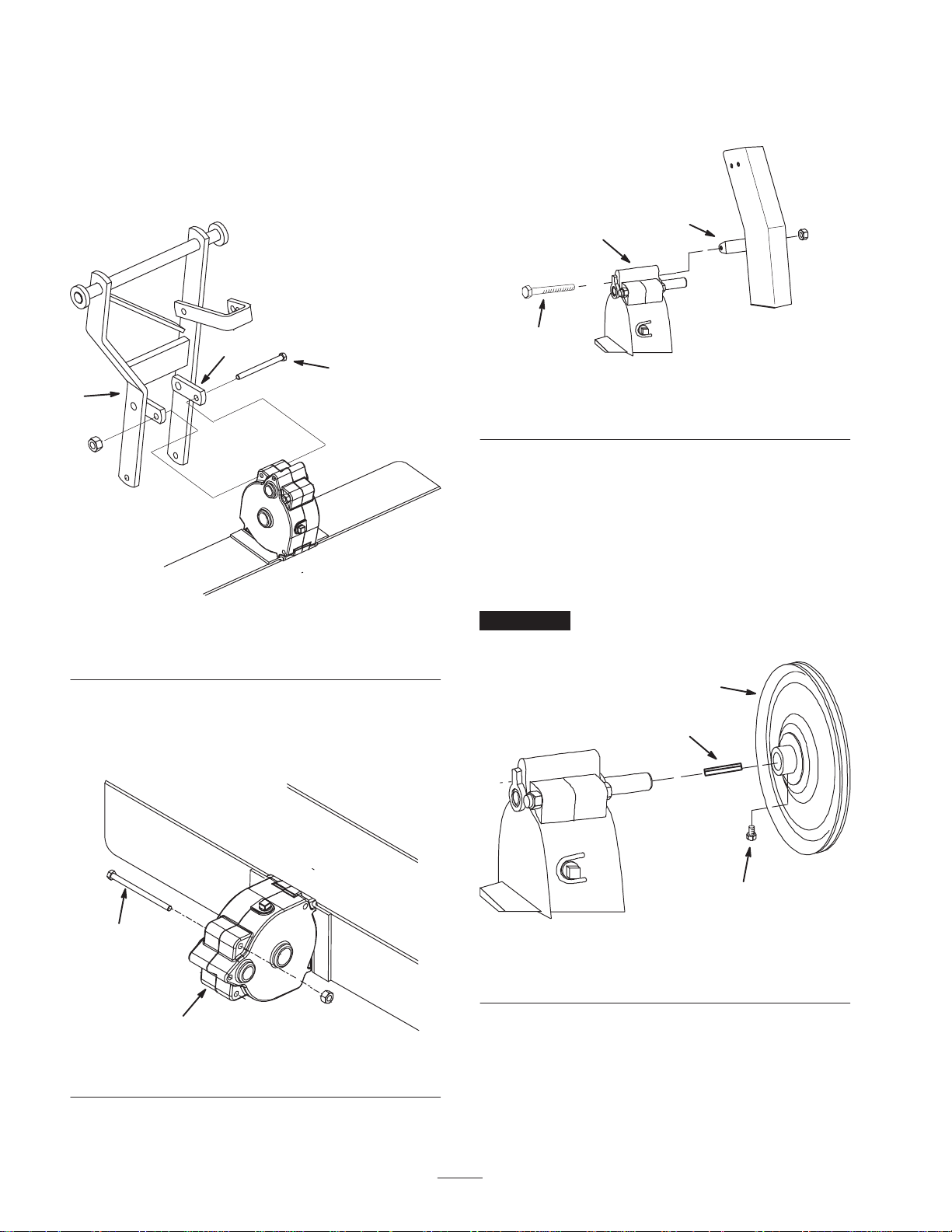
3. Loosely mount the hitch tabs to the front of the gear
case with the previously removed 3/8 x 4-1/2 inch bolt
and nut. Position as shown in figure 4.
Note: Make sure the bolt is positioned as shown in
figure 4.
4. Tighten the mounting bolts securely.
6. Loosely mount the belt cover tab to the gear case with
the 3/8 x 3–3/4 inch bolt and the 3/8 inch nut
previously removed (Fig. 6).
2
1
2
3
1
Figure 4
1. Hitch
2. Hitch tab
3. Bolt, 3/8 x 4–1/2 inch
5. Remove the 3/8 x 3–3/4 inch bolt and the 3/8 inch nut
securing the top front of the gear case together
(Fig. 2). Discard extra nuts used as spacers for
shipping.
3
Figure 6
1. Gear case
2. Belt cover
3. Bolt, 3/8 x 3–3/4 inch
Installing the Drive Pulley
1. Install the pulley to the gear case input shaft with a
square key and 2 square head set screws (5/16 inch)
(Fig. 7). The outside hub of the pulley is to be
positioned 1/4 inch from the end of the drive shaft
(Fig. 8).
Important The square key must be positioned under a
set screw to be retained.
1
2
2
1
Figure 5
1. Gear case 2. Bolt, 3/8 x 3–3/4 inch
1. Drive pulley
2. Key
6
3
Figure 7
3. Setscrews (2)
Page 7

2
Installing the Rear Shield
1. Rotate the tiller down and hook the rear shield into the
slots at the rear of the tine shield. Secure the shield to
the tiller with 3 cotter pins (1 inch) (Fig. 10).
3
1
Figure 8
1. Drive pulley 2. 1/4 inch
Installing the Idler Pulley and
Belt Guide
1. Mount the idler pulley, the spacer and the belt guide to
the belt guard and the hitch bracket with a bolt (3/8 x
2-1/4 inch) and a lock nut (3/8 inch). Use the lower
hole in the belt guard and the upper hole in the hitch
bracket. Position components as shown in figure 9.
7
4
6
1
4
2
Figure 10
1. Rear shield
2. Cotter pin, 1 inch
3. Slot
4. Tine shield
Installing the Lift Chain
1. Secure the short link end of the lift chain to the lift
bracket with a clevis, a clevis pin and a cotter pin
(3/4 inch) (Fig. 11).
1
2
3
3
5
1
Figure 9
1. Belt cover
2. Bolt, 3/8 x 2-1/4 inch
3. Upper hole in hitch
bracket
4. Belt guide
5. Lower hole in bracket
6. Idler pulley
7. Spacer
2. Tighten the belt cover mounting bolts.
5
2
4
Figure 11
1. Short link
2. Clevis
3. Clevis pin
4. Lift bracket
5. Cotter pin, 3/4 inch
7
Page 8

Installing the Lift Rod to the
Tractor
1. In front of the seat, remove the 4 bolts securing the
saddle plate to the top of the tractor frame (Fig. 12).
3. Remove the nut securing the idler pulley spring to the
pulley mounting bolt (Fig. 14).
3
1
Figure 12
1. Saddle plate
2. Move the traction belt off the traction idler pulley to
release tension on the pulley and belt (Fig. 13).
4
5
1
2
2
Figure 14
1. Idler pulley spring
2. Nut
3. Bolt
4. Idler pulley
5. Washer
4. Remove the nut, washer and bolt securing the idler
pulley to the idler bracket (Fig. 14).
5. Install the pulley to the idler bracket with a new 3/8 x
2–3/4 inch bolt, the existing washer, the new spacer
and the existing nut (Fig. 15).
1
1. Traction belt Idler pulley
Figure 13
2
3
2
4
6
5
5
Figure 15
1. Bolt, 3/8 x 2–3/4 inch
2. Idler pulley
3. Washer
4. Spacer
5. Nut
6. Idler pulley spring
1
6. Secure the spring to the new bolt with the other
existing nut (Fig. 15).
7. Move the traction belt onto the traction idler pulley.
8. From under the left side of the tractor, insert the
threaded end of attachment lift rod through the hole in
the rear of the frame (Fig. 16). The rod must be routed
8
Page 9

over the lift suspension cross shaft, under the pulley,
over the idler pulley spring and over the transaxle
(Fig. 16).
9. Insert the front, bent end of the attachment lift rod into
the lower hole in the attachment lift (Fig. 16). The rod
has to be inserted from the inside to the outside.
10.Secure the lift rod to the attachment lift with a washer
(3/8 inch) and a cotter pin (3/4 inch) (Fig. 16).
2
1
Installing the Jackshaft
1. Raise the attachment lift lever or electric lift all the
way up. Refer to the tractor operation on page 13.
2. Open the mid-mount hitch by pulling out the J–pin and
moving the lock handle rearward (Fig. 18).
1
m–6622
Figure 18
1. Front hitch
2. Mid-mount hitch
3. J–pin
4. Lock handle
4
2
3
4
5
3
Figure 16
1. Attachment lift rod
2. Attachment lift
3. Washer 3/8 inch
4. Cotter pin 3/4 inch
5. Hole in rear of frame
Installing the Lift Rod to the
Tiller
1. Thread the nut and the adjustable yoke onto the end of
the lift rod (Fig. 17). The end of the rod is to be flush
with the inside of adjustable yoke.
3. From the right side of the tractor, slide the jackshaft
assembly under the tractor. The curved end of the
jackshaft should be positioned toward the rear of the
tractor (Fig. 19).
2
3
1
1. Lift rod
2. Nut
1
Figure 17
2
3. Adjustable yoke
3
1. Jackshaft
2. Attachment lift cross shaft
9
Figure 19
3. Mid-mount hitch
Page 10

4. Hook the rear of the jackshaft under the right end of
the attachment lift cross shaft (Fig. 19).
5. Lift the front of the jack shaft until the tube fits into
the mid–mount hitch (Fig. 19).
6. Close the mid-mount hitch lock handle by rotating it
forward (Fig. 20).
3
1
2
m–6622
Figure 20
1. Mid-mount hitch
2. J–pin
3. Lock handle
4. Place the tiller mounting rod into the Attach–A–Matic,
then close the latches. Center the tiller between the
hitch latches (Fig. 22).
1
2
Figure 22
1. Attach–A–Matic latch rod 2. Tiller mounting rod
7. Hook the extension spring onto the jackshaft idler
pulley arm and onto the jackshaft eyelet (Fig. 21).
3
2
1
Figure 21
1. Extension spring
2. Idler pulley arm
3. Jackshaft eyelet
Installing the Tiller to the
Tractor
1. Park the machine on a level surface, disengage the
power take off (PTO), set the parking brake, stop the
engine and wait for all moving parts to stop. Remove
the ignition key.
2. Position the tiller behind the tractor so the mounting
rod is under the rear Attach–A–Matic hitch (Fig. 22).
3. Press in on the latch rod of the Attach–A–Matic hitch
and open the latches (Fig. 22).
5. Using the sixth chain link from the tiller end of chain,
secure the lift chain to the lift rod adjustable yoke with
a clevis pin and cotter pin (Fig. 23).
2
1
Figure 23
1. Sixth link 2. Adjustable yoke
6. Raise the attachment lift lever to the transport position
and place a block under the tiller gear case.
7. Install the bolt (3/8 x 1-1/2 inch), spacer, washer (3/8
inch) and lock nut (3/8 inch) into the left rear frame
member hole positioning as shown in Figure 24.
10
Page 11

2
3
2
1
4
Figure 24
1. Bolt 1/2 x 1-1/4 inch
2. Spacer
3. Washer 3/8 inch
8. Hook the spring catch over the rear tractor frame and
under the bolt spacer (Fig. 25). Hook the lift assist
spring through the spring catch and the eye bolt.
9. Install the eye bolt to the bracket with a lock nut
(3/8 inch) (Fig. 25). Adjust the lock nut so there is
light spring tension when in the fully raised position.
1
3
5
4
6
Figure 25
1. Spring catch
2. Spacer
3. Lift assist spring
4. Eye bolt
5. Bracket
6. Lock nut 3/8 inch
10.Install the jackshaft drive belt (shorter belt) onto the
left jackshaft pulley (Fig. 26).
11. Twist the front of the belt clockwise and install the
front of the belt onto the lower pulley and idler pulley
in the pulley box (Fig. 26).
1. Lower pulley
2. Idler pulley
Left side
4
2
3
6
Front of tractor
5
2
1
3
Right side
m–6777
Figure 26
3. Jackshaft pulley
4. Tiller pulley
5. Pulley box 6. Pivoting idler
11
Page 12

12.Turn the right knob on the front pulley box to tension
the belt. There needs to be a 1/2 inch (13 mm)
deflection in the belt.
13.Install the tiller drive belt (longer belt) under the
pivoting idler and onto the right jackshaft pulley
(Fig. 26).
14.Install the other end of the belt onto the tiller drive
pulley and idler pulley (Fig. 26).
Important Belts must be properly routed behind all
belt guides to prevent jumping off and premature failure.
Removing the Tiller from the
6. Press in on the latch rod of the Attach–A–Matic to
open the latches and remove the tiller mounting rod
(Fig. 28).
Tractor
Note: Save all the hardware, washers and hairpin cotters
for reuse when installing the tiller.
1. Park the machine on a level surface, disengage the
power take off (PTO), set the parking brake, stop the
engine and wait for all moving parts to stop. Remove
the ignition key.
2. Rotate the tiller drive pulley and slide the belt out of
the groove.
3. Raise the attachment lift to the transport position and
place a block under the tiller gear case.
4. Unhook the lift assist spring and the spring catch from
the tractor (Fig. 27).
5. Unhook the chain link of the lift chain from the lift
arm yoke (Fig. 27).
2
3
1
2
Figure 28
1. Attach–A–Matic latch rod 2. Tiller mounting rod
Note: Save all hardware, washers and hairpin cotters for
reuse when installing tiller.
1. Lift assist spring
2. Spring catch
1
Figure 27
3. Chain link
12
Page 13

Operation
Note: Determine the left and right sides of the machine
from the normal operating position.
Disengaging the Power Take Off (PTO)
1. Push the power take off (PTO) to the off position
(Fig. 29).
Warning
Rotating tines can cut hands, feet or other body
parts.
• Keep away from the rotating tines while
operating the tiller.
• Keep your hands, feet, and any other part of
your body or clothing away from rotating
parts.
• Before adjusting, cleaning, repairing and
inspecting the tiller, lower the tiller and loader
arms to the ground and turn off the engine.
Remove the key.
Operating the
Power Take Off (PTO)
The power take off (PTO) switch engages and disengages
power to the electric clutch.
The PTO light, in the Indicator Module, will be on when
the ignition key is in run or the lights position and the
power take off (PTO) is engaged. When this light is on, it
is a reminder the starter will not crank and to turn the off
PTO before getting off the tractor.
Using the Attachment Power
Lift
The attachment power lift (Fig. 30) is used to raise and
lower attachments.
Raising Attachments
1. Turn key to the on or run position (Fig. 30).
2. Push the lift switch in the up direction to raise the
attachment lift (Fig. 30). This will lift and hold the
attachment in the up, or raised position.
Lowering Attachments
1. Turn key to the on or run position (Fig. 30).
2. Push the lift switch in the down direction to lower the
attachment lift (Fig. 30). This will lower the
attachment lift.
2
3
1
Engaging the Power Take Off (PTO)
1. Move the throttle to the fast position.
2. Pull the power take off (PTO) to the on position
(Fig. 29).
1
Figure 29
1. PTO—Off 2. PTO—On
2
m–6524
1. Key
2. Lift switch —up
m–6513
Figure 30
3. Lift switch —down
13
Page 14

Operating the Attachment Lift
Lever
The attachment lift lever (Fig. 31) is used to raise and
lower various attachments.
Raising an Attachment
1. Depress the brake pedal to stop the machine.
2. Pull the attachment lift lever rearward until the latch
locks. In this position the lift will hold the attachment
in the up, or raised position.
Lowering an Attachment
1. Depress the brake pedal to stop the machine.
Adjusting the Lift Chain
Warning
Rotating tines can cut hands, feet or other body
parts.
• Keep away from the rotating tines while
operating the tiller.
• Keep your hands, feet, and any other part of
your body or clothing away from rotating
parts.
• Before adjusting, cleaning, repairing and
inspecting the tiller, lower the tiller and loader
arms to the ground and turn off the engine.
Remove the key.
2. Pull the attachment lift lever rearward, to release the
lift pressure, and push the button on top to release the
latch. Move the lift lever forward to lower the
attachment.
2
1
m–6531
Figure 31
1. Lift lever 2. Button
Changing the lift chain link at the clevis, affects
maximum tilling depth and transport lift height. These
links can be changed at the clevis (Fig. 32).
1. For maximum tilling depth, but reduced transport lift
height, lengthen the lift chain (Fig. 32).
2. For greater lift height, shorten the length of the lift
chain (Fig. 32). This position will have reduced tilling
depth.
1
Figure 32
3. Lift chain
3. For variations of less than a link in range, disconnect
chain from adjustable yoke on lift rod, loosen jam nut
and rotate the yoke clockwise to increase lift height
and tilling depth and counter clockwise to reduce lift
height and increase tilling depth (Fig. 32).
14
Page 15

Tips for Tilling
Clean the area of trash, branches and rocks before tilling
to prevent equipment damage.
Always begin tilling with the slowest ground speed
possible. Increase speed if conditions permit.
Always use full throttle (maximum engine speed) when
tilling.
Always engage the power take off (PTO) with tiller in the
raised position.
Till in long straight passes. Do not make turns while tiller
is in the ground, as equipment damage may result.
A small center area will not be tilled due to the gear case.
Overlapping with a second pass will eliminate this
condition.
Avoid excessive tilling of the soil, as finely tilled soil will
not absorb moisture easily and puddles of water or run-off
may occur.
When tilling hard packed, very dry or virgin soil, raise
tiller so only the very top of the soil is penetrated. On
succeeding passes the depth may be lowered. This reduces
the tendency of the tiller to push the tractor. If this
happens, disengage power take off (PTO) and reduce
forward speed.
15
Page 16

Maintenance
Note: Determine the left and right sides of the machine from the normal operating position.
Recommended Maintenance Schedule
Maintenance Service
Interval
25 Hours
Fall service
At storage service
Important Refer to your engine operator’s manual for additional maintenance procedures.
Maintenance Procedure
• Oil–check level
• Grease bearings
• Oil–check level
• Belt–check for wear/cracks
• Oil–check level
• Belt–check for wear/cracks
• Chipped Surfaces–paint
Caution
If you leave the key in the ignition switch, someone could accidently start the engine and
seriously injure you or other bystanders.
Remove the key from the ignition and disconnect the wire from the spark plug(s) before you do
any maintenance. Set the wire aside so that it does not accidentally contact the spark plug.
Greasing and Lubrication
Service Interval/Specification
4. If gear lube runs from the case when the plug is
removed, the lube in the case is sufficient. Oil may be
added as necessary.
Check the gear lube level in the gear case after every 25
operating hours or once a year, whichever occurs first.
Gear lube changes are not required.
Gear lube type: SAE 90-140 API service GL-4 or GL-5.
Refill capacity: 32 ounces.
Checking Gear Lube
1. Park the machine on a level surface, disengage the
power take off (PTO), set the parking brake, stop the
engine and wait for all moving parts to stop. Remove
the ignition key.
2. Clean the area around the lower pipe plug (Fig. 33).
3. Remove the pipe plug carefully because the oil level
may be above the level of the pipe plug.
Left side of tiller shown in operating position
1. Pipe plug (hidden)
16
Figure 33
1
m–3497
Page 17

Greasing the Tiller
Service Interval Specification
Grease the jack shaft bearings after every 25 operating
hours or once a year, whichever occurs first.
Grease Type: General-purpose grease.
Greasing the Bearings
1. Park the machine on a level surface, lower the
attachment, disengage the power take off (PTO), set
the parking brake, stop the engine and wait for all
moving parts to stop. Remove the ignition key.
2. With a clean rag, clean the area around the grease
fitting on the idler pulley pivot and on each flange
bearing (Fig. 34).
Figure 34
3. Apply grease to the fittings.
4. Wipe off excess grease.
17
Page 18

Storage
1. Before long term storage wash the machine with mild
detergent and water to remove dirt and grime from the
entire machine.
2. Check the condition of the tiller.
3. Check gearcase lubrication level; refer to Greasing and
Lubrication, page 16.
4. Check and tighten all bolts, nuts, and screws. Repair or
replace any part that is damaged or defective.
5. Paint all scratched or bare metal surfaces. Paint is
available from your Authorized Service Dealer.
6. Store the machine in a clean, dry garage or storage
area. Cover the machine to protect it and keep it clean.
18
Page 19

19
Page 20

Consumer
Riding
Products
The Toro Total Coverage Guarantee
A Two-Year Full Warranty
(Limited Warranty for Commercial Use)
Conditions and Products Covered
The Toro Company and its affiliate, Toro Warranty Company,
pursuant to an agreement between them, jointly promise to repair
any Toro Product used for normal residential purposes* if defective
in materials or workmanship. The following time periods apply
from the date of purchase:
Products
• All Products and Attachments 2 year full warranty
• 300, 400, and 5xi Series Tractors:
Frame 5 year full warranty
Front Axle 5 year full warranty
Drive Shaft (5xi Series Only) 5 year full warranty
• All Batteries 1 year full warranty
This warranty covers both the cost of parts and labor, and
transportation within a fifteen mile radius of the servicing dealer.
This warranty applies to all consumer riding products and their
attachments.
* Normal residential purposes means use of the product on the
same lot as your home. Use at more than one location is
considered commercial use, and the commercial use warranty
would apply.
Warranty Period
Limited Warranty for Commercial Use
Toro Consumer Products and attachments used for commercial,
institutional, or rental use are warranted against defects in
materials or workmanship for the following time periods from the
date of purchase:
Products
• 300, 400, and 5xi Series Tractors:
Liquid Cooled Gas Engines 1 year limited warranty
Air Cooled Gas and Diesel
Engines
All other items 1 year limited warranty
• TimeCutter Models
• All other Riding Products
Warranty Period
2 year limited warranty
30 day limited warranty
90 day limited warranty
Instructions for Obtaining Warranty Service
If you think that your T oro Product contains a defect in materials or
workmanship, follow this procedure:
1. Contact any Toro Authorized or Master Service Dealer to
arrange service at their dealership. To locate a dealer
convenient to you, refer to the Y ellow Pages of your telephone
directory (look under “Lawn Mowers”) or access our website at
www.Toro.com. U.S. Customers may also call 800-421-9684
to use our 24-hour Toro dealer locator system.
2. Bring the product and your proof of purchase (sales receipt) to
the Service Dealer.
If for any reason you are dissatisfied with the Service Dealer’s
analysis or with the assistance provided, contact us at:
Customer Care Department, Consumer Division
Toro Warranty Company
8111 Lyndale Avenue South
Bloomington, MN 55420-1196
800-348-2424 (U.S. customers)
877-484-9255 (Canada customers)
Owner Responsibilities
You must maintain your Toro Product by following the maintenance
procedures described in the operator’s manual. Such routine
maintenance, whether performed by a dealer or by you, is at your
expense.
Items and Conditions Not Covered
There is no other express warranty except for special emission
system coverage on some products. This express warranty does
not cover:
• Cost of regular maintenance service or parts, such as filters,
fuel, lubricants, tune-up parts, blade sharpening, brake and
clutch adjustments.
• Any product or part which has been altered or misused or
required replacement or repair due to normal wear, accidents,
or lack of proper maintenance.
• Repairs necessary due to improper fuel, contaminants in the
fuel system, or failure to properly prepare the fuel system prior
to any period of non-use over three months.
• Pickup and delivery charges for distances beyond a fifteen
mile radius from an Authorized Toro Service Dealer.
All repairs covered by this warranty must be performed by an
Authorized T oro Service Dealer using Toro approved replacement
parts.
General Conditions
Repair by an Authorized Toro Service Dealer is your sole remedy
under this warranty.
Neither The Toro Company nor Toro Warranty Company is liable
for indirect, incidental or consequential damages in connection
with the use of the Toro Products covered by this warranty,
including any cost or expense of providing substitute equipment or
service during reasonable periods of malfunction or non-use
pending completion of repairs under this warranty.
Some states do not allow exclusions of incidental or consequential
damages, or limitations on how long an implied warranty lasts, so
the above exclusions and limitations may not apply to you.
This warranty gives you specific legal rights, and you may also
have other rights which vary from state to state.
Countries Other than the United States or Canada
Customers who have purchased Toro products exported from the United States or Canada should contact their Toro Distributor (Dealer)
to obtain guarantee policies for your country, province, or state. If for any reason you are dissatisfied with your Distributor’s service or
have difficulty obtaining guarantee information, contact the Toro importer. If all other remedies fail, you may contact us at Toro Warranty
Company.
Part No. 374-0045 Rev. A
 Loading...