

Page 1

Form No. 3328–141 Rev A
42in Single–Stage Snowthrower
XT Series Garden Tractor Attachment
Model No. 79483—Serial No. 230000001 and Up
Operator’s Manual
English (EN)
Page 2
Contents
Introduction 2. . . . . . . . . . . . . . . . . . . . . . . . . . . . . . . . .
Safety 3. . . . . . . . . . . . . . . . . . . . . . . . . . . . . . . . . . . . . .
General Snowthrower Safety 3. . . . . . . . . . . . . . . . .
Preparation 3. . . . . . . . . . . . . . . . . . . . . . . . . . . . . . .
Operation 3. . . . . . . . . . . . . . . . . . . . . . . . . . . . . . . .
Maintenance and Storage 4. . . . . . . . . . . . . . . . . . . .
Toro Snowthrower Safety 4. . . . . . . . . . . . . . . . . . .
Safety and Instruction Decals 5. . . . . . . . . . . . . . . . .
Setup 6. . . . . . . . . . . . . . . . . . . . . . . . . . . . . . . . . . . . . .
Loose Parts 6. . . . . . . . . . . . . . . . . . . . . . . . . . . . . . .
Installing the Pulley Assembly 7. . . . . . . . . . . . . . . .
Installing the Frame 7. . . . . . . . . . . . . . . . . . . . . . . .
Installing the Snowthrower Drive Pulley 8. . . . . . . .
Installing the Side and Top Plates 8. . . . . . . . . . . . .
Installing the Discharge Chute and Worm Gear
Assembly 8. . . . . . . . . . . . . . . . . . . . . . . . . . . . . . .
Installing the Lift Bracket 9. . . . . . . . . . . . . . . . . . .
Installing the Lift Tube to the Snowthrower 9. . . . .
Installing the Snowthrower to the Tractor 10. . . . . . .
Installing the Belt and Belt Spring 13. . . . . . . . . . . . .
Installing the Chute Control Rod 13. . . . . . . . . . . . . .
Operation 14. . . . . . . . . . . . . . . . . . . . . . . . . . . . . . . . . . .
Operating the Power Take Off (PTO) 14. . . . . . . . . .
Using the Attachment Power Lift 14. . . . . . . . . . . . .
Operating the Attachment Lift Lever 15. . . . . . . . . . .
Adjusting the Discharge Chute 15. . . . . . . . . . . . . . .
Tips for Throwing Snow 16. . . . . . . . . . . . . . . . . . . .
Maintenance 17. . . . . . . . . . . . . . . . . . . . . . . . . . . . . . . . .
Recommended Maintenance Schedule 17. . . . . . . . .
Greasing and Lubrication 17. . . . . . . . . . . . . . . . . . . .
Adjusting the Skids 18. . . . . . . . . . . . . . . . . . . . . . . .
Reversing the Scraper Blade 18. . . . . . . . . . . . . . . . .
Adjusting the Drive Chain Tension 19. . . . . . . . . . . .
Removing the Snowthrower 19. . . . . . . . . . . . . . . . . .
Storage 21. . . . . . . . . . . . . . . . . . . . . . . . . . . . . . . . . .
Troubleshooting 22. . . . . . . . . . . . . . . . . . . . . . . . . . . . . .
The Toro Total Coverage Guarantee 24. . . . . . . . . . . . . .
Page
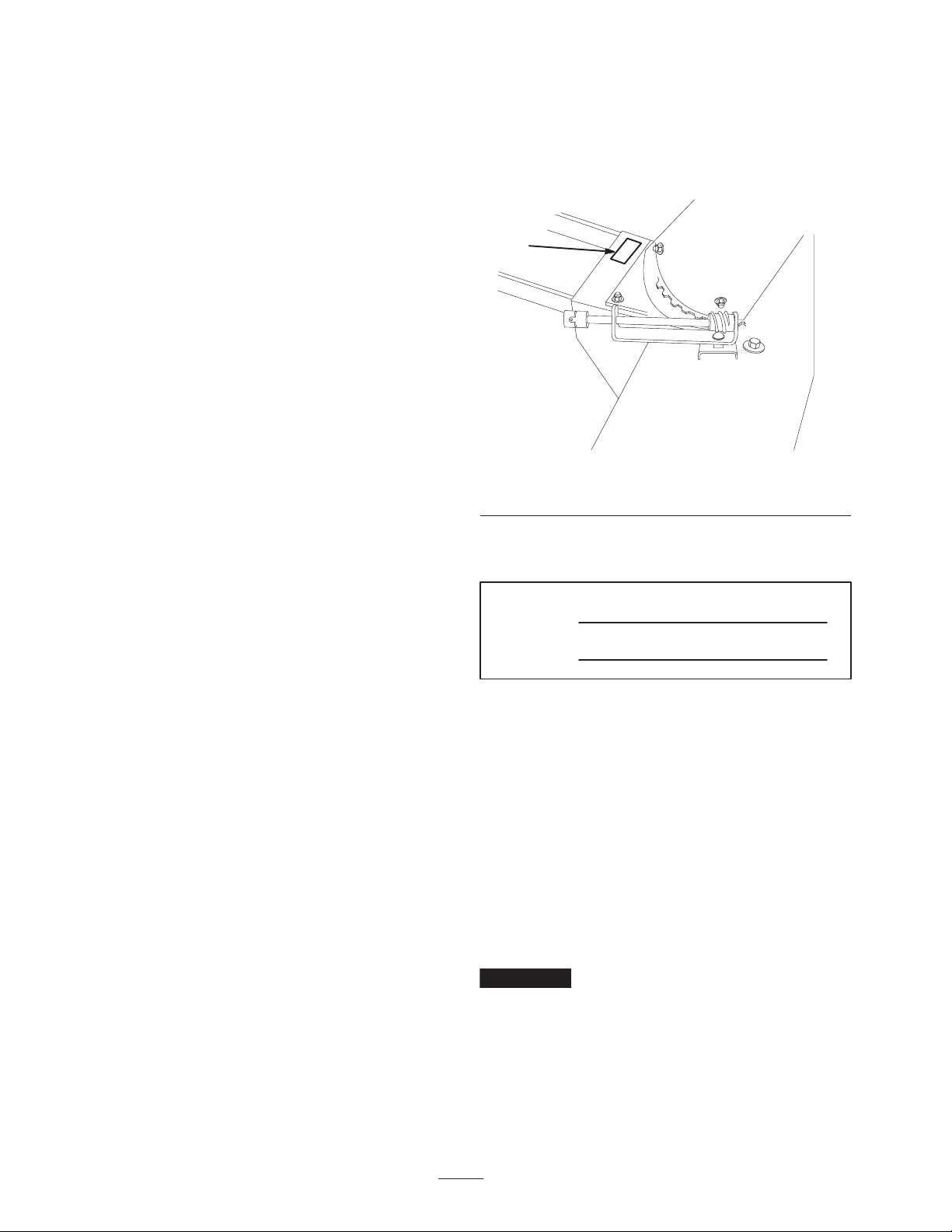
Whenever you need service, genuine Toro parts, or
additional information, contact an Authorized Service
Dealer or Toro Customer Service and have the model and
serial numbers of your product ready. Figure 1 illustrates
the location of the model and serial numbers on the
product.
1
1280
Figure 1
1. Location of the model and serial numbers
Write the product model and serial numbers in the space
below:
Model No.
Serial No.
This manual identifies potential hazards and has special
safety messages that help you and others avoid personal
injury and even death. Danger, Warning, and Caution are
signal words used to identify the level of hazard. However,
regardless of the hazard, be extremely careful.
Danger signals an extreme hazard that will cause serious
injury or death if you do not follow the recommended
precautions.
Warning signals a hazard that may cause serious injury or
death if you do not follow the recommended precautions.
Caution signals a hazard that may cause minor or moderate
injury if you do not follow the recommended precautions.
Introduction
Read this manual carefully to learn how to operate and
maintain your product properly. The information in this
manual can help you and others avoid injury and product
damage. Although Toro designs and produces safe
products, you are responsible for operating the product
properly and safely.
2003 by The Toro Company
8111 Lyndale Avenue South
Bloomington, MN 55420-1196
This manual uses two other words to highlight information.
Important calls attention to special mechanical
information and Note: emphasizes general information
worthy of special attention.
All Rights Reserved
Printed in the USA
2
Page 3

Safety
Improper use or maintenance by the operator or owner
can result in injury. To reduce the potential for injury,
comply with the safety instructions in the traction unit
operator’s manual and always pay attention to the
safety alert
WARNING, or DANGER—“personal safety
instruction.” Failure to comply with the instruction may
result in personal injury or death.
symbol, which means CAUTION,
• Do not operate the equipment without wearing adequate
winter outer garments. Wear footwear that will improve
footing on slippery surfaces.
• Adjust the auger housing height to clear gravel or
crushed rock surface.
• Never attempt to make any adjustments while the
engine is running, except when specifically
recommended by Toro.
• Let engine and machine adjust to outdoor temperatures
before starting to clear snow.
Danger
When the snowthrower is in operation, the
impeller and auger can be rotating and cut off or
injure hands and feet.
• Before adjusting, cleaning, repairing and
inspecting the snowthrower, and before
unclogging the discharge chute, stop the engine
and wait for all moving parts to stop. Remove the
key.
• Use a stick, not your hands, to remove an
obstruction from the discharge chute.
• Stay behind the handles and away from the
discharge opening while operating the
snowthrower.
• Keep face, hands, feet, and any other part of
your body or clothing away from concealed,
moving, or rotating parts.
Warning
The auger/impeller may pick up and throw stones,
toys, and other foreign objects, causing serious
personal injury to the operator or to bystanders.
• Keep the area to be cleared free of all objects
that could be picked up and thrown by the
auger/impeller.
• Keep all children and pets away from area of
operation.
General Snowthrower Safety
The following instructions have been adapted from the
ANSI/OPEI and ISO standards.
Preparation
• Thoroughly inspect the area where the equipment is to
be used and remove all doormats, sleds, boards, wires,
and other foreign objects.
• The operation of any powered machine can result in
foreign objects being thrown into the eyes. Always wear
safety glasses or eye shields during operation or while
performing an adjustment or repair.
Operation
• Do not put hands or feet near or under rotating parts.
Keep clear of the discharge opening at all times.
• Exercise extreme caution when operating on or crossing
gravel drives, walks, or roads. Stay alert for hidden
hazards or traffic. Do not carry passengers.
• After striking a foreign object, stop the engine, remove
the wire(s) from the spark plug(s), thoroughly inspect
the snowthrower for any damage, and repair the damage
before restarting and operating the snowthrower.
• If the unit should start to vibrate abnormally, stop the
engine and check immediately for the cause. Vibration
is generally a warning of trouble.
• Stop the engine whenever you leave the operating
position, before unclogging the auger/impeller housing
or discharge chute, and when making any repairs,
adjustments, or inspections.
• When cleaning, repairing, or inspecting, make certain
the auger/impeller and all moving parts have stopped.
Disconnect the spark plug wire(s) and keep the wire
away from the plug to prevent someone from
accidentally starting the engine.
• Do not clear snow across the face of slopes. Exercise
extreme caution when changing direction on slopes. Do
not attempt to clear steep slopes.
• Never operate the snowthrower without proper guards,
plates, or other safety protective devices in place.
• Never operate the snow thrower near glass enclosures,
automobiles, window wells, drop-offs, and the like
without proper adjustment of the snow discharge angle.
Keep children and pets away.
• Do not overload the machine capacity by attempting to
clear snow at too fast a rate.
3
Page 4

• Never operate the machine at high transport speeds on
slippery surfaces. Look behind and use care when
moving in reverse.
• Never direct discharge at bystanders or allow anyone in
front of the unit.
• Disengage power to the auger/impeller when the
snowthrower is transported or not in use.
• Never operate the snowthrower without good visibility
or light.
Maintenance and Storage
• Check fasteners at frequent intervals for proper
tightness to be sure the equipment is in safe working
condition.
• Always refer to the operator’s manual for important
details if the snowthrower is to be stored for an
extended period.
• Maintain or replace safety and instruction labels, as
necessary.
• Run the machine a few minutes after throwing snow to
prevent freeze-up of the auger/impeller.
• Perform only those maintenance instructions described
in this manual. Before performing any maintenance,
service, or adjustment, stop the engine, remove the key
and pull the wire(s) from the spark plug(s), keeping it
away from the plug(s) to prevent someone form
accidentally starting the engine. If major repairs are
ever needed, contact your Authorized Toro Service
Dealer.
• To ensure the best performance and safety, purchase
only genuine Toro replacement parts and accessories to
keep the Toro all Toro. Do not use “Will Fit”
replacement parts and accessories as they could
cause a safety hazard.
Toro Snowthrower Safety
The following list contains safety information specific to
Toro products or other safety information that you must
know that is not included in the ANSI or ISO standards.
• The rotating auger/impeller or rotor blades can cut
off or injure fingers or hands. Stay in the operator’s
position and away from the discharge opening while
operating the snowthrower. Keep your face hands,
feet, and any other part of your body or clothing
away from concealed, moving, or rotating parts.
• Before adjusting, cleaning, repairing, and inspecting the
snowthrower, and before unclogging the dischar ge
chute, stop the engine, remove the key, and wait for
all moving parts to stop. Also, pull the wire(s) off of
the spark plug(s) and keep it away from the plug(s) to
prevent someone from accidentally starting the engine.
• Use a stick, not your hands to remove obstructions
from the discharge chute.
• Before leaving the operator’s position, stop the engine,
remove the key, and wait for all moving parts to stop.
• Do not wear loose fitting clothing that could possibly
get caught in moving parts.
• If a shield, safely device, or decal is damaged, illegible,
or lost, repair or replace it before beginning operation.
Also, tighten any loose fasteners.
• Do not use the snowthrower on a roof.
4
Page 5
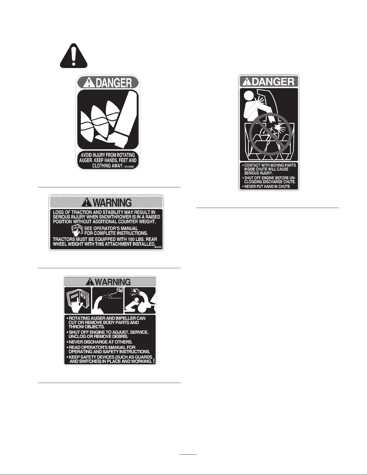
Safety and Instruction Decals
Safety decals and instructions are easily visible to the operator and are located near any area
of potential danger. Replace any decal that is damaged or lost.
63-2380
94-8079
86-5100
92-8652
5
Page 6

Setup
Note: Determine the left and right sides of the machine
from the normal operating position.
Loose Parts
Note: Use the chart below to identify parts used for assembly.
Description Qty. Use
Pulley assembly
Cotter pin, 3/32 x 1 inch
Washer, 17/32 inch
Housing
Frame
Bolt, 3/8 x 1 inch
Locknut, 3/8 inch
Pulley
Key
Square head bolt, 5/16 x 1/2 inch
Top plate
Side plate
Long shoulder bolt, 3/8 x 1 inch
Washer, 3/8 inch
Locknut, 3/8 inch
Discharge chute, upper
Discharge chute, lower
Deflector shield
Carriage bolt, 5/16 x 3/4 inch
Bolt, 5/16 x 5/8 inch
Washer, 5/16 inch
Locknut, 5/16 inch
Worm gear assembly
Carriage bolt, 5/16 x 1 inch
Lock washer, 5/16 inch
1
1
2
1
1
4
4
1
1
2
1
2
9
9
9
1
1
1
3
3
6
7
1
1
1
Installing the pulley assembly
Installing the frame
Installing the snowthrower drive pulley
Installing the top and side plates
Installing the discharge chute and worm gear
assembly
Lift bracket
Support rod
Cotter pin
Washer, 17/32 inch
Washer, 21/32 inch
Hairpin cotter pin
1
1
2
2
1
1
6
Installing the lift bracket
Page 7
Description UseQty.
Lift tube
Clevis pin
Pin clip
Eyebolt
Locknut, 3/8 inch
Hairpin cotter pin
Washer, 5/8 inch
Snowthrower assembly
Stop rod
Chute control rod support
Hairpin cotter pin, 1-7/8 inch
Lift spring
Belt
Belt spring
Chute control rod
Hairpin cotter pin
Note: It is recommended to install wheel weights and
chains while using this snowthrower. Please contact an
Authorized Service Dealer to acquire a wheel weight kit
and chains.
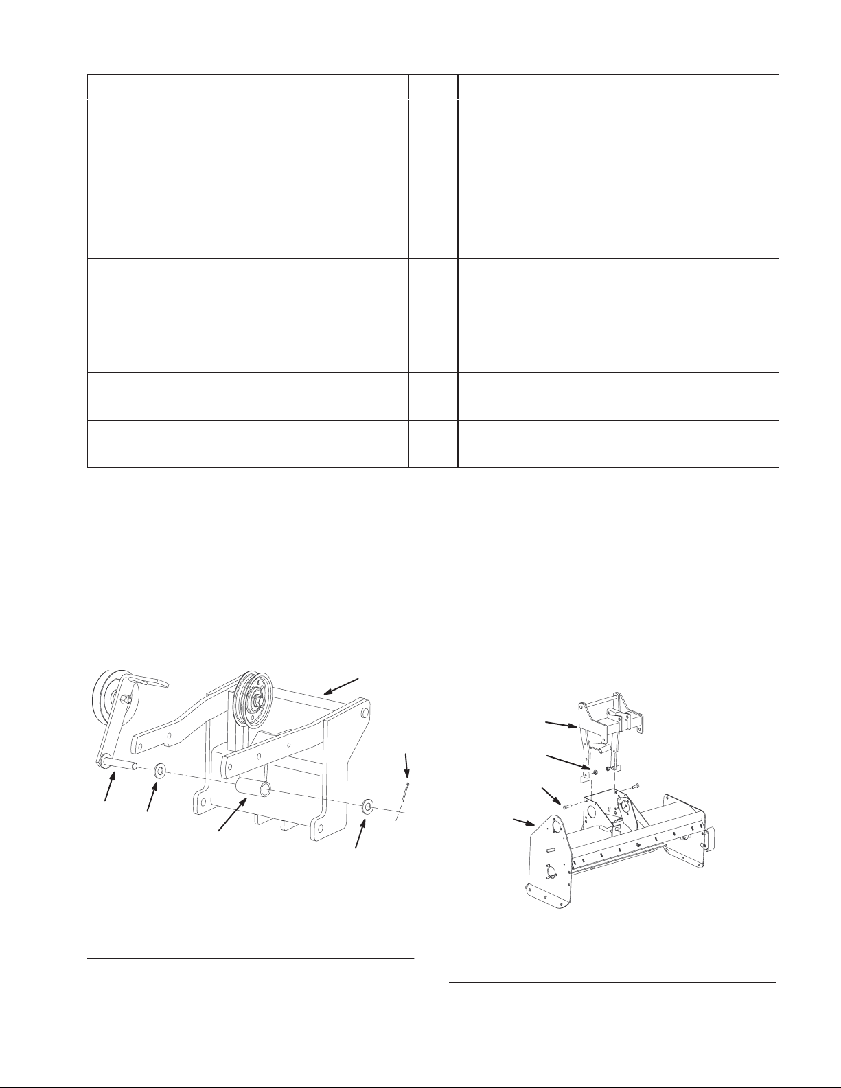
Installing the Pulley Assembly
1. Install the pulley assembly into the pivot tube with
bushings and secure it with a washer and cotter pin
(Fig. 2).
4
1
1
1
1
Installing the lift tube to the snowthrower
1
1
11
1
1
1
Installing the snowthrower to the tractor
1
1
1
Installing the belt and belt spring
1
1
Installing the chute control rod
1
Installing the Frame
1. Tip the housing onto its front.
2. Place the frame onto the snowthrower housing and align
the holes (fig. 3).
3. Secure the frame to the housing with 4 bolts (3/8 x
1 inch), with the bolt heads to the outside, and 4 lock
nuts (3/8 inch) (Fig. 3).
4. Rotate the housing down into the normal operating
position.
5
m–6992
1. Pivot tube
2. Washer, 17/32 inch
3. Cotter pin
2
1
Figure 2
2
4. Frame
5. Pulley assembly
2
3
4
3
1
m–6991
Figure 3
1. Housing
2. Frame
3. Bolt, 3/8 x 1 inch
4. Locknut, 3/8 inch
7
Page 8
Installing the Snowthrower
Drive Pulley
1. Install the key into the slot in the shaft (Fig. 4). The key
may need to be lightly tapped in with a hammer.
2. Align the pulley with the key and slide the pulley onto
the shaft (Fig. 4). The long hub needs to be facing
towards the outside of the snowthrower.
1
4
3
4
3
3. Install the 2 square head bolts (5/16 x 1/2 inch) into the
long hub (Fig. 4). Do not tighten the bolts, the pulley
will need to be adjusted when installing the belt.
4. Rotate the housing down into the normal operating
position.
2 3
6
5
1
4
5
m–7107
Figure 4
1. Housing
2. Shaft
3. Pulley
4. Key
5. Square head bolt, 5/16 x
1/2 inch
6. Long hub
5
2
6
2 5
1281
Figure 5
1. Top plate
2. Carriage bolt, 3/8 x 1 inch
3. Washer, 3/8 inch
4. Locknut, 3/8 inch
5. Side plate
6. Housing
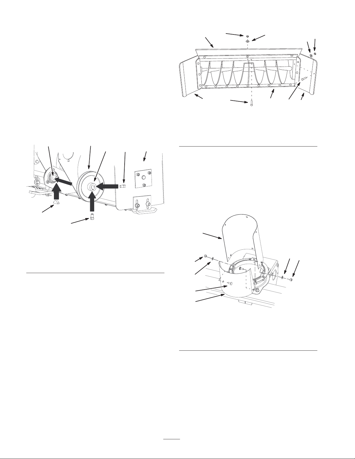
Installing the Discharge Chute
and Worm Gear Assembly
1. Install the lower discharge chute and deflector shield
onto the housing with 3 carriage bolts (5/16 x 3/4 inch)
(heads to the inside), 3 washers (5/16 inch), and
3 locknuts (5/16 inch) (fig. 6).
1
4
5
5
Installing the Side and Top
Plates
1. Position the top plate on top of the top housing flange
and secure it with 3 carriage bolts (3/8 x 1 inch) (heads
on the inside), 3 washers (3/8 inch), and 3 locknuts
(3/8 inch) (Fig. 5).
2. Position the side plates on the outside of the housing
side flanges and secure them with 6 carriage bolts
(3/8 x 1 inch) (heads on the inside), 6 washers
(3/8 inch), and 6 locknuts (3/8 inch) (Fig. 5).
4
3
2
1. Discharge chute
2. Deflector shield
3. Carriage bolt, 5/16 x
3/4 inch
8
m–7106
Figure 6
4. Washer, 5/16 inch
5. Locknut, 5/16 inch
Page 9

2. Assemble the upper discharge chute on top and outside
of the lower section with 3 bolts (5/16 x 5/8 inch)
(heads on the inside), 3 washers (5/16 inch), and
3 locknuts (5/16 inch) (fig. 7).
1
2. Install the lift bracket to the snowthrower frame with a
support rod, 2 washers (17/32 inch) and 2 cotter pins
(Fig. 9).
3
4
2
5
1290
Figure 7
1. Upper section
2. Lower section
3. Bolt, 5/16 x 5/8 in.
4. Washer, 5/16 inch
5. Locknut, 5/16 inch
3. Install the discharge chute worm gear assembly into the
slot on the rightside of the housing with a carriage bolt
(5/16 x 1 inch) (head to the top), lock washer
(5/16 inch), and locknut (5/16 inch) (fig. 8).
4. Adjust the rotator assembly so that the worm gear is at a
right angle with the chute, the chute teeth mesh fully,
and the chute turns freely (fig. 8).
5. Tighten the locknut securely (fig. 8).
6
5
7
5
1
2 4
4
3
Figure 9
1. Lift bracket
2. Washer, 5/8 inch
3. Washer, 17/32 inch
4. Hairpin cotter pin
5. Snowthrower frame
6. Support rod
7. Snowthrower
Installing the Lift Tube to the
46
3
m–6993
1
3
1280
Figure 8
1. Worm gear assembly
2. Carriage bolt, 5/16 x 1 in.
3. Lock washer, 5/16 in.
4. Locknut, 5/16 inch
5. Worm gear
6. Chute teeth
Installing the Lift Bracket
1. Install the lift bracket to the snowthrower with a flat
washer (5/8 inch) and a hairpin cotter (fig. 9).
Snowthrower
1. Install the lift tube to the snowthrower frame with a
clevis pin and a pin clip (Fig. 10).
2
4
2
1
m–6994
1. Lift tube
2. Clevis pin
3
Figure 10
3. Pin clip
9
Page 10

2. Install the eyebolt and locknut (3/8 inch) to the end of
6
the lift tube (Fig. 11). Install the eyebolt so it is flush
with the locknut.
3. Install 11 washers (5/8 inch) onto the lift rod and then
install the lift rod into the lift tube (Fig. 11 and 21).
2
4
1
3
3
m–6995
4
1
5
3
4
3
Figure 11
1. Lift tube
2. Eyebolt
3. Locknut, 3/8 inch
4. Washers, 5/8 inch
5. Lift Rod
6. Hairpin cotter pin
Installing the Snowthrower to
the Tractor
Removing the Hood
If desired, remove the hood for better access to the upper
pulleys in the pulley box.
1. Rotate the hood fully forward (Fig. 12).
2. Disconnect the wire harness at the front left of the
machine. The harness leads up the to the head lights
(Fig. 12).
3. Slide the hood to the left side of the machine and off of
the pivot pegs (fig. 12).
2
5
5
3
Figure 12
1. Hood—open position
2. Engine
3. Pivot peg
4. Wire harness
5. Harness connector
Installing the Snowthrower
Caution
The snowthrower adds a lot of weight to the front
of the tractor, causing poor traction and an
unstable condition which could result in a loss of
control.
Install the 100lb rear wheel weights (sold
separately).
1. Position the snowthrower on a flat surface with the
frame and lift tube extending rearward (Fig. 13).
m–6647
1 2
m–7037
3
Figure 13
1. Tractor
2. Snowthrower
3. Lift tube
10
Page 11

2. Park the tractor behind the snowthrower, with the lift
tube between the front wheels (Fig. 13 and 14).
2
2
1
Figure 14
1. Tractor 2. Front hitch
3. Disengage the power take off (PTO), set the parking
brake, stop the engine and remove the key.
4. Slide the snowthrower mounting frame into the top
front hitch slot. Close and lock the front hitch (Fig. 15).
1 2
m–6622
m–6622
1
m-6997
Figure 16
1. Stop rod
2. Front hitch
3. Cotter pin
6. Install the lift tube to the attachment lift with a hairpin
cotter pin (Fig. 17).
3
3
m–6996
Figure 15
1. Tractor
2. Front hitch
3. Snowthrower mounting
frame
5. Install the stop rod into the front hitch and secure it with
a hairpin cotter pin (Fig. 16).
2
3
1
M–6998
Figure 17
1. Lift rod
2. Tractor attachment lift
3. Hairpin cotter pin
7. Open the mid-mount hitch by pulling out the J–pin and
moving the lock handle rearward (Fig. 18).
11
Page 12

2
4
1
m–6622
Figure 18
1. Front hitch
2. Mid-mount hitch
3. J–pin
4. Lock handle
8. Install the closed loop end of the spring onto the chute
control rod support (Fig. 19).
2
2
1
3
3
m–6999
Figure 20
1. Mid–mount hitch
2. Control rod support
3. Lift spring
10.Close the mid-mount hitch by moving the lock handle
forward and by pulling out the J–pin and locking it into
place (Fig. 18).
11. Install the lift spring into the lifttube eyebolt (fig. 21).
12.Adjust the eye bolt until there is 1 inch (26 mm) of the
threads past the nut (fig. 21).
1
m–7039
Figure 19
1. Lift spring 2. Chute control rod support
9. Install the chute control rod support into the mid–mount
hitch (fig. 20).
12
Page 13

1. Lift spring
2. Lift tube
4. Hook the other end of the spring into the belt idler arm
(fig. 22).
4
1
2
4
1
3
2
m–7000
1. Belt
2. Tractor clutch
Figure 23
3. Snowthrower frame
4. Belt idler arm
3
m–7001
Figure 21
3. Eyebolt
4. 1 inch (26 mm)
5. Align the hood onto the pivot pegs and slide the hood to
the right side of the machine (fig. 24).
4
Installing the Belt and Belt
Spring
1. Hook one end of the belt spring onto the snowthrower
spring peg (Fig. 22).
3
m–7002
1. Belt spring
2. Idler arm
1
2
Figure 22
3. Snowthrower spring peg
1
3
2
5
5
3
Figure 24
1. Hood—open position
2. Engine
3. Pivot peg
4. Wire harness
5. Harness connector
6. Connect the harness and close the hood (Fig. 24).
3
m–6647
2. Route the belt around the clutch pulley and the
snowthrower pulleys (fig. 23).
3. Adjust the snowthrower drive pulley to align the belt
and tighten the 2 square head bolts (5/16 x 1/2 inch)
into the long hub (Fig. 4).
Installing the Chute Control
Rod
1. Slide the crank handle through the hole in the rod
support and secure the handle to the U-joint with a
hairpin cotter (1-7/8 inch) (fig. 25).
13
Page 14

Note: Adjust the worm gear assembly if necessary so the
handle clears the tractor hood, the teeth mesh fully, and the
chute turns freely.
4
1
2
1. Crank handle
2. Support
3
1292
Figure 25
3. U-joint
4. Hairpin cotter, 1-7/8 inch
Operation
Note: Determine the left and right sides of the machine
from the normal operating position.
Operating the
Power Take Off (PTO)
The power take off (PTO) switch engages and disengages
power to the electric clutch.
The PTO light, in the Indicator Module, will be on when
the ignition key is in run or the lights position and the
power take off (PTO) is engaged. When this light is on, it is
a reminder the starter will not crank and to turn the off PTO
before getting off the tractor.
Engaging the Power Take Off (PTO)
1. Move the throttle to the fast position.
2. Pull the power take off (PTO) to the on position
(Fig. 26).
1
Figure 26
1. PTO—Off 2. PTO—On
2
Disengaging the Power Take Off (PTO)
1. Push the power take off (PTO) to the off position
(Fig. 26).
Using the Attachment Power
Lift
The attachment power lift (Fig. 27) is used to raise and
lower attachments.
Raising Attachments
m–6524
1. Turn key to the on or run position (Fig. 27).
2. Push the lift switch in the up direction to raise the
attachment lift (Fig. 27). This will lift and hold the
attachment in the up, or raised position.
14
Page 15

Lowering Attachments
1. Turn key to the on or run position (Fig. 27).
2. Push the lift switch in the down direction to lower the
attachment lift (Fig. 27). This will lower the attachment
lift.
2
2. Pull the attachment lift lever rearward, to release the lift
pressure, and push the button on top to release the latch.
Move the lift lever forward to lower the attachment.
2
1
3
1. Key
2. Lift switch —up
Figure 27
3. Lift switch —down
1
m–6513
Operating the Attachment Lift
Lever
The attachment lift lever (Fig. 28) is used to raise and lower
various attachments.
Raising an Attachment
1. Depress the brake pedal to stop the machine.
2. Pull the attachment lift lever rearward until the latch
locks. In this position the lift will hold the attachment in
the up, or raised position.
Lowering an Attachment
1. Depress the brake pedal to stop the machine.
m–6531
Figure 28
1. Lift lever 2. Button
Adjusting the Discharge Chute
Danger
When the snowthrower is in operation, the
impeller and auger can be rotating and cut off or
injure hands and feet.
• Before adjusting, cleaning, repairing and
inspecting the snowthrower, and before
unclogging the discharge chute, disengage the
PTO, stop the engine, remove the key, and wait
for all moving parts to stop.
• Use a stick, not your hands, to remove an
obstruction from the discharge chute.
• Stay away from the discharge and auger
openings while operating the snowthrower.
• Keep face, hands, feet, and any other part of
your body or clothing away from concealed,
moving, or rotating parts.
You can rotate the discharge chute 180 degrees side to side
by turning the crank handle (fig. 29).
15
Page 16

You can adjust the height and distance snow is thrown by
moving the chute deflector, on top of the discharge chute,
up and down (fig. 29).
3
2
1
1290a1292a
Figure 29
1. Discharge chute
2. Crank handle
3. Chute deflector
Tips for Throwing Snow
Remove snow as soon as possible after it falls. This
produces the best snow removal results.
Adjust the skids to match the type of surface being cleaned;
refer to Adjusting Skids.
The snowthrower is designed to clean snow down to the
contact surface, but there are times when the front of the
snowthrower may tend to ride up. If this happens, reduce
forward speed.
Discharge snow downwind whenever possible, and overlap
each pass to ensure complete snow removal.
If the wheels slip, shift into a lower gear to reduce forward
speed.
Run the snowthrower for a few minutes after clearing snow
so moving parts do not freeze. Engage the PTO to clear any
remaining snow from inside the housing.
Do not overload the snowthrower by clearing snow at too
fast a rate. If the engine slows down, reduce forward speed.
Always use full throttle (maximum engine speed) when
throwing snow.
In wet or slushy conditions, reduce clogging of the
discharge chute by maintaining maximum engine speed and
by not overloading the engine.
In some snow and cold weather conditions, some controls
and moving parts may freeze. Therefore, when any control
becomes hard to operate, stop the machine and wait for all
moving parts to stop; then check all parts for freeze up. Do
not use excessive force trying to operate frozen controls.
Free all controls and moving parts before operating.
16
Page 17

Maintenance
Note: Determine the left and right sides of the machine from the normal operating position.
Recommended Maintenance Schedule
Maintenance Service
Interval
25 hours
Pre-storage service
Fall service
If you leave the key in the ignition switch, someone could accidently start the engine and
seriously injure you or other bystanders.
Remove the key from the ignition and disconnect the wire from the spark plug before you do any
maintenance. Set the wire aside so that it does not accidentally contact the spark plug.
Maintenance Procedure
• Grease the drive shaft bearings
• Oil the drive chain
• Grease the drive shaft bearings
• Oil the drive chain
• Check the belt for wear and cracks
• Check the scraper for wear
• Paint chipped surfaces
• Grease the drive shaft bearings
• Oil the drive chain
• Check the belt for wear and cracks
• Check the scraper for wear
Caution
Greasing and Lubrication
Grease and oil the machine after every 25 operating hours
or once a year, whichever occurs first.
Grease Type: General-purpose grease.
Oil Type: SAE 10W or 10W30.
Greasing the Snowthrower
1. Disengage the PTO and set the parking brake.
2. Stop the engine, remove the key, and wait for all
moving parts to stop before leaving the operating
position.
3. Clean the grease fittings with a rag. Make sure to scrape
any paint off the front of the fittings.
4. Connect a grease gun to each fitting and pump grease
into them (fig. 30).
m–7042
Figure 30
5. Wipe up any excess grease.
Oiling the Drive Chain
1. Disengage the PTO, set the parking brake, stop the
engine, and remove the key.
17
Page 18

2. Coat the entire chain with oil and allow it to penetrate
each roller (fig. 31).
2
1293
3
1280
Figure 31
1. Drive chain
2. Rotator assembly
3. Discharge chute mounting
3. Place a few drops of oil on the discharge chute rotator
shaft and discharge chute mounting (fig. 31).
4. Wipe off excess oil.
Adjusting the Skids
The distance between the scraper blade and the ground is
controlled by skids on each side of the housing. The height
can be adjusted so the scraper blade will not catch on
uneven surfaces
1. Move the snowthrower to a level surface.
2. Disengage the PTO and set the parking brake.
3. Stop the engine, remove the key, and wait for all
moving parts to stop before leaving the operating
position.
4. Loosen the nuts securing skids to the housing until the
skids slide up and down easily (fig. 32).
1
1284
Figure 32
1. Skid
2. Housing
3. Nut
5. Raise or lower the skids equally on both sides, to obtain
level scraping action, then tighten the nuts (fig. 32).
Note: On smooth, paved surfaces, the scraper blade can be
close to the surface On uneven, gravel or crushed rock
surfaces, adjust the skids to raise the scraper, to prevent
catching or picking up rocks.
Important The scraper should be higher above the
pavement if the pavement surfaces on which the
snowthrower will be used are cracked, rough or uneven.
Reversing the Scraper Blade
The scraper blade contacts the ground preventing damage
to the snowthrower housing. Periodically inspect the
scraper blade for wear. When the scraper becomes worn,
before the working surface contacts the housing, reverse the
scraper blade.
1. Disengage the PTO and set the parking brake.
2. Stop the engine, remove the key, and wait for all
moving parts to stop before leaving the operating
position.
3. Raise the attachment lift lever and support the housing
off the ground; refer to Raising Attachments.
4. Remove the nuts, washers, carriage bolts, and scraper
blade (fig. 33).
18
Page 19

3
2
4
1281a1
Figure 33
1. Nut
2. Washer
3. Carriage bolt
4. Scraper blade
5. Reverse the scraper blade and install it with previously
removed hardware (fig. 33).
Adjusting the Drive Chain
Tension
Removing the Snowthrower
Note: Save all hardware use when removing the
snowthrower.
1. Disengage the PTO and set the parking brake.
2. Stop the engine, remove the key, and wait for all
moving parts to stop before leaving the operating
position.
3. Raise the attachment to the transport position.
4. Remove the hairpin cotter at the U-joint and slide the
crank handle out of the support (fig. 35).
4
1
Check the drive chain tension after every 25 operating
hours or once a year, whichever occurs first. Adjustment as
necessary to maintain proper tension.
1. Disengage the PTO and set the parking brake.
2. Stop the engine, remove the key, and wait for all
moving parts to stop before leaving the operating
position.
3. Loosen the bolt that secures the idler sprocket to the left
side of the housing. (fig. 34).
1
2
m–7041
Figure 34
1. Idler sprocket bolt 2. Adjustment slot
4. Slide the idler sprocket in the adjustment slot until the
chain is snug, but not tight (Fig. 34).
2
3
Figure 35
1. Crank handle
2. Support
3. U-joint
4. Hairpin cotter
5. Pull on the drive belt idler pulley to relax the belt
tension and remove the drive belt from the tractor
clutch (fig. 36).
4
1
2
3
Figure 36
1. Belt
2. Tractor clutch
3. Snowthrower frame
4. Belt idler arm
1292
m–7001
5. Tighten the idler sprocket securely.
Important Do not overtighten the chain or excessive
wear will occur.
6. Loosen the eye bolt attached to the lift tube (fig. 37).
19
Page 20

7. Remove the lift spring from the lifttube eyebolt
(Fig. 37).
1
2
3
2
Figure 37
1. Lift spring 2. Lift tube eyebolt
8. Remove the lift tube from the attachment lift by
removing hairpin cotter pin (Fig. 38).
m–7000
1
M–6998
Figure 38
1. Lift tube
2. Tractor attachment lift
3. Hairpin cotter pin
9. Open the mid-mount hitch by pulling out the J–pin and
moving the lock handle rearward (Fig. 39).
1
m–6622
Figure 39
1. Front hitch
2. Mid-mount hitch
3. J–pin
4. Lock handle
4
2
3
10.Remove the the chute control rod support from the
mid–mount hitch (fig. 40).
20
Page 21

1
1 2
2
m–7057
Figure 40
1. Mid–mount hitch
2. Control rod support
3. Lift spring
11. Remove the stop rod from the front hitch by removing
the hairpin cotter pin (fig. 41).
2
1
m–7058
Figure 41
1. Stop rod
2. Front hitch
3. Cotter pin
12.Open the front hitch on the tractor (fig. 42)
3
m–7059
Figure 43
1. Tractor
2. Front hitch
3. Snowthrower mounting
frame
Storage
1. Before long term storage, wash the machine with mild
detergent and water to remove dirt and grime from the
3
entire machine.
2. Check the condition of the scraper blade; refer to
Reversing the Scraper Blade, page 18.
3. Check the condition of the snowthrower belt and drive
chain.
4. Grease and oil the snowthrower; refer to Greasing and
Lubrication, page 17.
5. Check and tighten all bolts, nuts, and screws. Repair or
replace any part that is damaged or defective.
6. Paint all scratched or bare metal surfaces. Paint is
available from your Authorized Service Dealer.
7. Coat the inside of the auger housing and discharge
chute with automotive wax to prevent rust and reduce
the sticking of snow to these surfaces.
2
Figure 42
1. Tractor 2. Front hitch
13.Slide the snowthrower out from the front hitch
(Fig. 43).
8. Store the machine in a clean, dry garage or storage area.
Cover the machine to protect it and keep it clean.
1
m–6622
21
Page 22

Troubleshooting
Problem Possible Causes Corrective Action
Snow does not discharge
Auger does not rotate.
Abnormal vibration.
1. The discharge chute is
plugged.
2. The auger does not rotate. 2. Refer to Auger does not rotate.
3. Auger speed too low. 3. Move the throttle to Fast.
4. Forward speed too slow. 4. Increase ground speed.
1. Snow is frozen to the auger or
housing.
2. The drive belt tension is low. 2. Adjust the belt tension.
3. The drive belt is worn, loose or
broken.
4. The drive belt is off the pulley. 4. Install the drive belt and check
5. The drive chain is broken. 5. Replace or repair the chain.
1. Snow is frozen to the auger. 1. Scrape snow off with stick.
2. The drive belt is off a pulley. 2. Install the drive belt and check
3. The engine mounting bolts are
loose.
1. Clean the chute with a stick.
1. Scrape snow off with a stick.
3. Install a new drive belt.
the idler pulley for correct
position.
the idler pulley for correct
position.
3. Tighten the engine mounting
bolts.
4. Loose engine pulley, idler, or
snowthrower pulley.
5. The engine pulley is damaged. 5. Contact your Authorized
4. Tighten the appropriate pulley.
Service Dealer.
22
Page 23

23
Page 24

Consumer
Riding
Products
The Toro Total Coverage Guarantee
A Two-Year Full Warranty
(Limited Warranty for Commercial Use)
Conditions and Products Covered
The Toro Company and its affiliate, Toro Warranty Company,
pursuant to an agreement between them, jointly promise to repair
any Toro Product used for normal residential purposes* if defective
in materials or workmanship. The following time periods apply
from the date of purchase:
Products
• All Products and Attachments 2 year full warranty
• 300, 400, and 5xi Series Tractors:
Frame 5 year full warranty
Front Axle 5 year full warranty
Drive Shaft (5xi Series Only) 5 year full warranty
• All Batteries 1 year full warranty
This warranty covers both the cost of parts and labor, and
transportation within a fifteen mile radius of the servicing dealer.
This warranty applies to all consumer riding products and their
attachments.
* Normal residential purposes means use of the product on the
same lot as your home. Use at more than one location is
considered commercial use, and the commercial use warranty
would apply.
Warranty Period
Limited Warranty for Commercial Use
Toro Consumer Products and attachments used for commercial,
institutional, or rental use are warranted against defects in
materials or workmanship for the following time periods from the
date of purchase:
Products
• 300, 400, and 5xi Series Tractors:
Liquid Cooled Gas Engines 1 year limited warranty
Air Cooled Gas and Diesel
Engines
All other items 1 year limited warranty
• TimeCutter Models
• All other Riding Products
Warranty Period
2 year limited warranty
30 day limited warranty
90 day limited warranty
Instructions for Obtaining Warranty Service
If you think that your Toro Product contains a defect in materials or
workmanship, follow this procedure:
1. Contact any Toro Authorized or Master Service Dealer to
arrange service at their dealership. To locate a dealer
convenient to you, refer to the Yellow Pages of your telephone
directory (look under “Lawn Mowers”) or access our website at
www.Toro.com. U.S. Customers may also call 800-421-9684
to use our 24-hour Toro dealer locator system.
2. Bring the product and your proof of purchase (sales receipt) to
the Service Dealer.
If for any reason you are dissatisfied with the Service Dealer’s
analysis or with the assistance provided, contact us at:
Customer Care Department, Consumer Division
Toro Warranty Company
8111 Lyndale Avenue South
Bloomington, MN 55420-1196
800-348-2424 (U.S. customers)
877-484-9255 (Canada customers)
Owner Responsibilities
Y ou must maintain your Toro Product by following the maintenance
procedures described in the operator’s manual. Such routine
maintenance, whether performed by a dealer or by you, is at your
expense.
Items and Conditions Not Covered
There is no other express warranty except for special emission
system coverage on some products. This express warranty does
not cover:
• Cost of regular maintenance service or parts, such as filters,
fuel, lubricants, tune-up parts, blade sharpening, brake and
clutch adjustments.
• Any product or part which has been altered or misused or
required replacement or repair due to normal wear, accidents,
or lack of proper maintenance.
• Repairs necessary due to improper fuel, contaminants in the
fuel system, or failure to properly prepare the fuel system prior
to any period of non-use over three months.
• Pickup and delivery charges for distances beyond a fifteen
mile radius from an Authorized Toro Service Dealer.
All repairs covered by this warranty must be performed by an
Authorized Toro Service Dealer using Toro approved replacement
parts.
General Conditions
Repair by an Authorized Toro Service Dealer is your sole remedy
under this warranty.
Neither The Toro Company nor Toro Warranty Company is liable
for indirect, incidental or consequential damages in connection
with the use of the Toro Products covered by this warranty,
including any cost or expense of providing substitute equipment or
service during reasonable periods of malfunction or non-use
pending completion of repairs under this warranty.
Some states d o n o t a l l o w exclusions of incidental or consequential
damages, or limitations on how long an implied warranty lasts, so
the above exclusions and limitations may not apply to you.
This warranty gives you specific legal rights, and you may also
have other rights which vary from state to state.
Countries Other than the United States or Canada
Customers who have purchased Toro products exported from the United States or Canada should contact their Toro Distributor (Dealer)
to obtain guarantee policies for your country , province, or state. If for any reason you are dissatisfied with your Distributor’s service or
have difficulty obtaining guarantee information, contact the Toro importer. I f all other remedies fail, you may contact us at Toro Warranty
Company.
Part No. 374-0045 Rev. A
 Loading...