

Page 1

48in Snow/Dozer Blade
XT Series Garden Tractors
Model No. 79481—Serial No. 230000001 and Up
Form No. 3329-318
Operator ’s Manual
Original Instructions (EN)
Page 2
Contents
Introduction 2. . . . . . . . . . . . . . . . . . . . . . . . . . . . . . . .
Setup 3. . . . . . . . . . . . . . . . . . . . . . . . . . . . . . . . . . . . .
Loose Parts 3. . . . . . . . . . . . . . . . . . . . . . . . . . . . . .
Assembling the Blade 4. . . . . . . . . . . . . . . . . . . . . .
Removing the Pulley Box 4. . . . . . . . . . . . . . . . . . .
Modifying the Front Attach-A-Matic) Hitch 5. . . .
Installing the Rear Attach-A-Matic Hitch 5. . . . . .
Installing the Dozer Extension onto the Frame 5. .
Installing the Blade Assembly 5. . . . . . . . . . . . . . .
Installing the Anti-sway Bar 6. . . . . . . . . . . . . . . . .
Installing the Control Handle 7. . . . . . . . . . . . . . . .
Removing the Blade 8. . . . . . . . . . . . . . . . . . . . . . .
Operation 8. . . . . . . . . . . . . . . . . . . . . . . . . . . . . . . . . .
Operating the Attachment Power Lift 8. . . . . . . . .
Operating the Attachment Lift Lever 9. . . . . . . . . .
Adjusting the Blade Angle 9. . . . . . . . . . . . . . . . . .
Adjusting the Blade Trip Springs 9. . . . . . . . . . . . .
Tips for Using the Blade 10. . . . . . . . . . . . . . . . . . . .
Maintenance 10. . . . . . . . . . . . . . . . . . . . . . . . . . . . . . . .
Recommended Maintenance Schedule 10. . . . . . . . .
Greasing and Lubricating the Blade 10. . . . . . . . . . .
Reversing the Scraper 11. . . . . . . . . . . . . . . . . . . . . .
Cleaning and Storing the Blade 11. . . . . . . . . . . . . .
The Toro Total Coverage Guarantee 12. . . . . . . . . . . . .
serial numbers of your product ready. Figure 1 illustrates
the location of the model and serial numbers on the
product.
Page
1
m-1237
Figure 1
1. Model and serial number plate
Write the product model and serial numbers in the space
below:
Model No.
Serial No.
This manual identifies potential hazards and has special
safety messages that help you and others avoid personal
injury and even death. Danger, Warning, and Caution are
signal words used to identify the level of hazard. However,
regardless of the hazard, be extremely careful.
Introduction
Read this manual carefully to learn how to operate and
maintain your product properly. The information in this
manual can help you and others avoid injury and product
damage. Although Toro designs and produces safe
products, you are responsible for operating the product
properly and safely.
You may contact Toro directly at www.Toro.com for
product and accessory information, help finding a dealer, or
to register your product.
Whenever you need service, genuine Toro parts, or
additional information, contact an Authorized Service
Dealer or Toro Customer Service and have the model and
Danger signals an extreme hazard that will cause serious
injury or death if you do not follow the recommended
precautions.
Warning signals a hazard that may cause serious injury or
death if you do not follow the recommended precautions.
Caution signals a hazard that may cause minor or moderate
injury if you do not follow the recommended precautions.
This manual uses 2 other words to highlight information.
Important calls attention to special mechanical
information and Note: emphasizes general information
worthy of special attention.
2003 by The Toro Company
8111 Lyndale Avenue South
Bloomington, MN 55420-1196
Contact us at www.Toro.com
All Rights Reserved
2
Printed in the USA
Page 3

Setup
Loose Parts
Note: Use the chart below to identify parts used for assembly.
Description Qty. Use
Blade assembly
Rod
Control rod
Cotter pins, 1/8 x 1 inch
Frame
Bolt, 3/4 x 3-3/4 inch
Locknut, 3/4 inch
Catch assembly
Stop rod, 5/16 inch
Push nut
Hairpin cotter
Locknuts, 5/16 inch
Dozer extension
Shaft
Hairpin cotters
Anti-sway bar assembly 1 Installing the anti-sway bar
Lift channel and channel plate
Lift link
Hairpin cotters
Locknut, 3/8 inch
Bolt, 3/8 x 1 inch
Clevis pins, 3/8 x 7/8 inch
1
1
1
3
1
1
1
1
1
1
1
2
1
1
2
1
1
2
1
1
2
Assembling the blade
Modifying the front Attach-A-Matic hitch
Installing the dozer extension onto the frame
Installing the blade assembly
Control handle assembly
Pivot bolt, 1/2 x 1 inch
Jam nut, 1/2 inch
Hairpin cotter, large
Cable clips
Bolts, 1/4 x 1 inch
Locknuts, 1/4
Cable
Cable bracket
Cotter pin, 1-1/4 in
1
1
1
1
3
Installing the control handle
3
3
1
1
1
3
Page 4
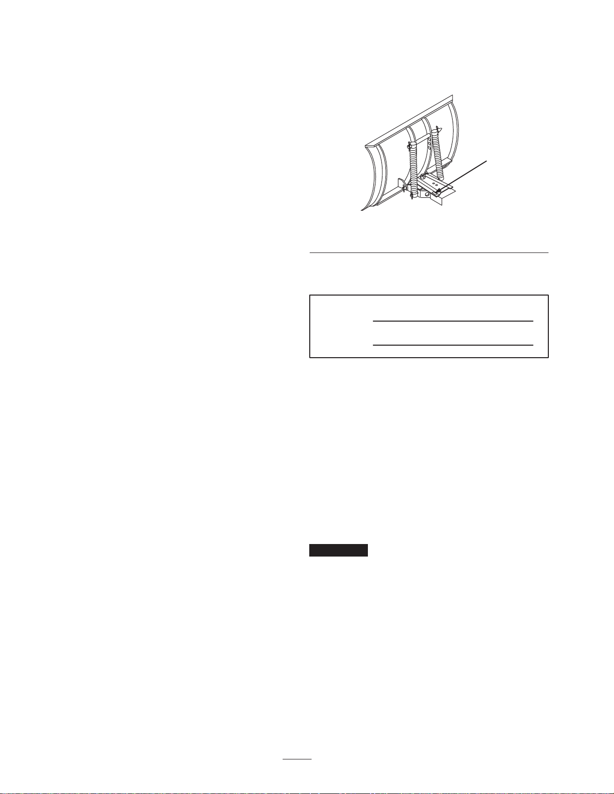
Assembling the Blade
1. Lift and rotate the channel and trip spring assembly so
that the holes align with the lower blade mounts
(Fig. 2).
4
3
6. Apply general-purpose grease to the pivot area of the
frame and channel (Fig. 4).
4
5
2
3
Figure 2
1. Channel
2. Rod
3. Cotter pin, 1/8 x 1 inch
4. Trip spring assembly
2. Slide the rod through the holes and secure it with
2 cotter pins (1 inch) as shown in Figure 2.
Note: If you have difficulty sliding the rod through the
holes, partially remove the upper rod and use a hammer
to drive the rod through. Then install the upper rod.
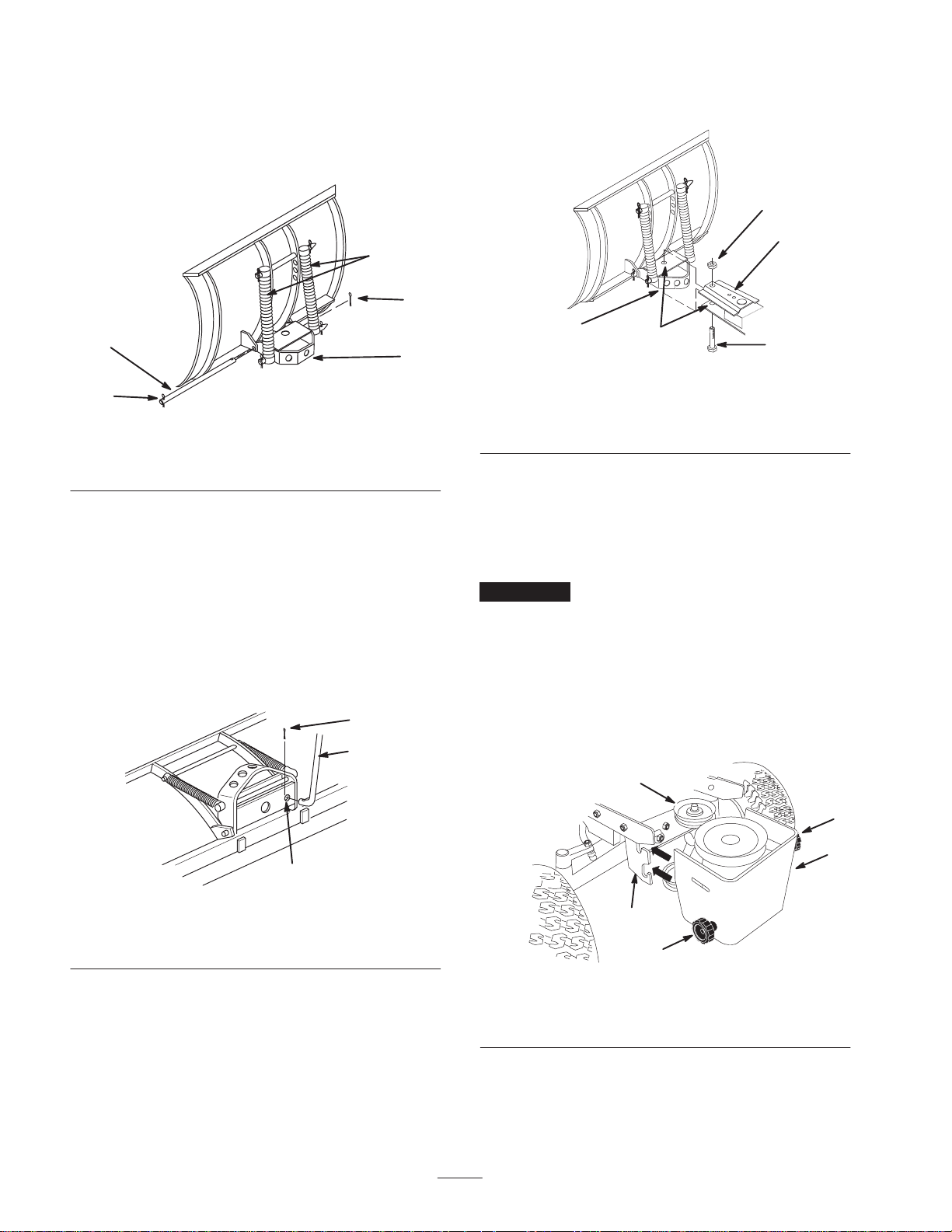
3. Bend the ends of the cotter pins to secure the rod.
4. Insert the end of the control rod without the welded
washer through the 1/2-inch hole in the bottom plate of
the channel (Fig. 3).
3
1
1
m-269
1
2
m-1469
3
Figure 4
1. Channel
2. Grease here
3. Bolt, 3/4-16 x 3-3/4 inch
4. Locknut, 3/4 inch
5. Frame mount
7. Slide the channel into the frame mount and secure it
with a bolt (3/4-16 x 3-3/4 inch) and a locknut
(3/4 inch) as shown in Figure 4.
Note: Insert the bolt from the underside of the frame
mount as shown in Figure 4.
Important Do not tighten the locknut and bolt
excessively.
Removing the Pulley Box
If the pulley box is installed on the tractor, remove it.
1. Turn the knobs to loosen the belts on the idler pulleys
(Fig. 5).
4
2
m-3271
Figure 3
1. Control rod
2. 1/2-inch hole
3. Cotter pin, 1/8 x 1 inch
5. Insert a cotter pin (1/8 x 1 inch) through the hole in the
rod and bend the ends of the pin (Fig. 3).
1
3
Figure 5
1. Front Attach-A-Matic
2. Pulley box
3. Knob
4. Idler pulley (2)
2. Remove the PTO belt from the upper pulley and the
mower drive belt from the lower pulley.
4
3
2
m–6620
Page 5

3. Pull the release lever and remove the pulley box
(Fig. 6).
Installing the Rear
Attach-A-Matic Hitch
Ensure that the rear Attach-A-Matic is installed on your
tractor. Refer to your Installation Instructions for the rear
Attach-A-Matic kit.
1
Figure 6
1. Release lever
Note: The pulley box is not shown in Figure 6 for the
purpose of clarity.
m-6622
Modifying the Front
Attach-A-Matic
1. Remove the release lever from the front
Attach-A-Matic hitch (Fig. 6).
2. Install the new release lever on the hitch using the
hardware as shown in Figure 7.
m-6814
Hitch
Installing the Dozer Extension
onto the Frame
1. Insert the bar at the back end of the frame into the
notches in the dozer extension (Fig. 8).
2
1
4
3
Figure 8
1. Back end of frame
2. Dozer extension
1
2. Align the holes in the dozer extension with the holes in
the frame (Fig. 8).
3. Slide the shaft through the holes in the frame (Fig. 8).
3. Shaft
4. Hairpin cotters
m-6816
2
m-6817
Figure 7
1. Front Attach-A-Matic 2. Release lever assembly
3. Use a screwdriver to hook the spring end around the
side of the release lever as shown in Figure 12.
4. Insert the 2 hairpin cotters as shown in Figure 8.
Installing the Blade Assembly
1. Position the blade on a level surface and allow space
behind it for the tractor.
2. Park the tractor over the blade with the frame between
the wheels.
3. Set the parking brake.
4. Stop the engine and wait for all moving parts to stop.
5. Remove the ignition key.
5
Page 6

6. Push the end of the latch rod to open the latches on the
rear Attach-A-Matic hitch (Fig. 9).
1
Installing the Anti-sway Bar
1. Insert the anti-sway bar into the front Attach-A-Matic
until it locks into place (Fig. 11).
2
3
m-6799
4
Figure 9
1. Push here to open the
latches
2. Latch rod
3. Dozer extension end
4. Frame
7. Lift and insert the dozer extension end into the open
slots in the hitch.
8. Close the latches (Fig. 9).
9. Insert the lift channel with channel plate into the frame
(Fig. 10).
1
3
7
2
6
4
8
m-6800
5
Figure 10
1. Attachment lift arm
2. Lift link
3. Clevis pin, 3/8 x 7/8 inch
4. Hairpin cotter
5. Frame plate
6. Channel plate
7. Bolt
8. Frame
1
m-6801
Figure 11
1. Anti-sway bar
2. Insert a push nut onto the end of the stop rod (Fig. 12)
that does not have the hole.
3
4
1
2
m-6818
Figure 12
1. Spring
2. Hook the spring end here
3. Stop rod
4. Push nut
3. Insert the stop rod in the front Attach-A-Matic as shown
in Figure 12.
4. Insert a hairpin cotter through the hole in the stop rod
and bend the ends of the hairpin cotter to secure it.
10.Secure the channel plate to the frame plate with a bolt
and a locknut.
11. Install the lower end of the lift link to the channel plate
with a clevis pin and a hairpin cotter.
12.Secure the attachment lift arm to the upper end of the
lift link with a clevis pin and a hairpin cotter.
6
Page 7

Installing the Control Handle
1. Attach the control handle to the pivot support using the
pivot bolt (1/2 x 1 inch) as shown in Figure 13.
2
1
3
9
10
7. Thread the balled end of the cable through the keyhole
slot in the frame up to the fitting on the cable jacket
(Fig. 14).
1
7
5
6
5
8
9, 10, 11
4
7
6
m-5070
Figure 13
1. Control handle
2. Release lever
3. Z-fitting on the cable
4. Pivot support
5. Pivot bolt
6. Jam nut, 1/2 inch
7. Control rod
8. Large hairpin cotter
9. Cable clips
10. Locknut, 1/4-20 inch
11. Bolt, 1/4 x 1 inch
2. Screw the bolt into the pivot support until the handle is
snug and then back it off slightly to let the handle pivot
freely (Fig. 13).
3. Install the jam nut (1/2 inch) on the pivot bolt to lock it
in place (Fig. 13).
4. Rotate the control handle to align the hole at the bottom
of the handle with the control rod (Fig. 13).
2
3
4
6
7
m-5040/m-5041
Figure 14
1. Rear view
2. Front view
3. Cable jacket
4. Cable
5. Fitting
6. Keyhole slot
7. Jam nuts
8. Slide the fitting through the slot and push it to the right
and ensure that there is a jam nut on each side of the
frame (Fig. 14).
9. Tighten the jam nuts.
10.Thread the cable through the anti-sway bar (Fig. 15).
5. Insert the control rod end through the handle end and
secure it with a large hairpin cotter (Fig. 13).
6. Connect the Z-fitting on the end of the cable to the
release lever (Fig. 13).
1
2
m-6801a
Figure 15
1. Anti-sway bar 2. Cable
7
Page 8

11. Insert the balled end of the cable into the cable bracket.
3
4
1
1
4
2
m–5043
Figure 16
1. Cable bracket
2. Cable
3. Angle pin
4. Cotter pin, 1-1/4 inch
12.Attach the cable bracket to the angle pin at the blade
assembly (Fig. 16) with a cotter pin (1-1/4 inch).
Note: Put the cotter pin through the hole that removes
the most slack from the cable.
13.Bend the ends of the cotter pin.
14.Pull down on the cable jacket to remove the slack and
secure the cable to the handle using 3 cable clips,
3 bolts (1/4 x 1 inch), and 3 locknuts (1/4-20 inch) as
shown in Figure 13.
1
2
3
m-6799
4
Figure 17
1. Push here to open the
latches
2. Latch rod
3. Dozer extension end
4. Frame
8. Remove the dozer extension end and frame.
9. Slide the blade and frame out between front wheels of
the tractor.
Operation
Operating the Attachment
Removing the Blade
Note: Save all hardware, rods, washers and hairpin cotters
for future use.
1. Park the tractor on a level surface.
2. Set the parking brake.
3. Stop the engine and wait for all moving parts to stop.
4. Remove the ignition key.
5. Lower the blade using the attachment power lift or the
attachment lift lever; refer to Operating the Attachment
Power Lift on page 8 or Operating the Attachment Lift
Lever on page 9.
6. Remove the hairpin cotter and clevis pin that secures
the attachment lift arm from the upper end of the lift
link (Fig. 10).
7. Push the end of the latch rod to open the latches on the
rear Attach-A-Matic hitch (Fig. 17).
Power Lift
Use the attachment power lift (Fig. 18) to raise and lower
the blade.
Raising the Blade
1. Turn key to the On or Run position (Fig. 18).
2
3
1. Key
2. Lift switch —up
Figure 18
3. Lift switch —down
1
m-6513
2. Push the lift switch in the Up direction to raise the
attachment lift (Fig. 18).
Note: This lifts and holds the attachment in the raised
position.
8
Page 9

Lowering the Blade
1. Turn key to the On or Run position (Fig. 18).
2. Push the lift switch in the down direction to lower the
attachment lift (Fig. 18).
Note: This lowers the attachment lift.
Adjusting the Blade Angle
You can set the angle of the blade in 5 positions using the
control handle on the right-hand side of the frame (Fig. 20).
1. Squeeze the release lever toward the handle (Fig. 20).
Operating the Attachment Lift
Lever
Use the lift lever (Fig. 19) to raise and lower the blade.
2
1
m-6802
Figure 19
1. Lift lever 2. Button
Raising the Blade
1. Depress the brake pedal to stop the tractor.
2. Pull the attachment lift lever rearward until the latch
locks it in place.
Note: In this position, the lift will hold the attachment
in the raised position.
Lowering the Blade
2
Figure 20
1. Handle 2. Release lever
2. Push or pull the handle to change the angle.
3. Release the lever and pull or push the handle until the
locking pin on the blade snaps into place.
1
m-6803
Adjusting the Blade Trip
Springs
You can mount the blade trip springs in 4 positions. The top
hole provides the greatest scraping pressure and the bottom
hole provides the least scraping pressure (Fig. 21).
1
4
1. Depress the brake pedal to stop the tractor.
2. Push the button on top to release the latch.
3. Pull the attachment lift lever rearward to release the lift
pressure.
4. Move the lift lever forward to lower the attachment.
2
Figure 21
1. Hairpin cotter
2. Rod
Note: Use the second hole from the top for removing snow.
1. Remove the hairpin cotter and slide the rod from the
blade and springs (Fig. 21).
3. Spring
4. Top hole
3
9
m-3395
Page 10

2. Slide the rod through the springs and the new hole
position in the blade (Fig. 21).
• Remove snow from a driveway by making one pass
down the center and then plowing snow to either side
on successive passes.
Tips for Using the Blade
The following lists contains information that will help you
obtain the best possible results with your blade:
• Remove snow as soon as possible after it falls.
• If the tractor loses traction when using the snow blade,
install wheel weights and/or tire chains available from
an Authorized Service Dealer.
• Install the optional skid shoe kit to control the height of
blade from the ground for even scraping, if desired.
Maintenance
Recommended Maintenance Schedule
Maintenance Service
Interval
25 hours
Annually/Storage
Maintenance Procedure
• Grease the channel pivot.
• Oil the linkages.
• Grease the channel pivot.
• Oil the linkages.
• Examine the scraper for wear and replace if damaged or worn.
• Paint chipped surfaces with paint available from an Authorized Service Dealer.
Caution
If you leave the key in the ignition switch, someone could accidently start the engine and
seriously injure you or other bystanders.
Remove the key from the ignition and disconnect the wire from the spark plug before you do any
maintenance. Set the wire aside so that it does not accidentally contact the spark plug.
Greasing and Lubricating the Blade
Service Interval Specification
Grease and oil the blade after every 25 operating hours or
once a year, whichever occurs first.
Grease Type: General-purpose grease
Oil Type: SAE 10W or 10W30.
Greasing the Channel Pivot
1. Lower the attachment.
2. Set the parking brake.
3. Stop the engine and wait for for all moving parts to
stop.
4. Remove the ignition key.
5. Clean the area around the channel pivot with a rag.
Apply grease to the pivot bolt, frame and sector
(Fig. 22).
m-1473
Figure 22
10
Page 11

6. Wipe off the excess grease.
Cleaning and Storing the Blade
Oiling the Linkages
1. Set the parking brake.
2. Stop the engine and wait for for all moving parts to
stop.
3. Remove the ignition key.
4. Place a few drops of oil on all movable linkages
(Fig. 22).
5. Wipe off any excess oil.
Reversing the Scraper
The scraper contacts the ground, preventing damage to the
snow blade. Periodically inspect the scraper for wear. When
the scraper is worn and before the working surface contacts
the housing, reverse the scraper.
1. Start the tractor.
2. Raise the blade.
3. Support the housing off the ground.
4. Set the parking brake.
1. Before long-term storage, wash the blade with mild
detergent and water to remove dirt and grime.
2. Check the condition of the scraper; refer to Reversing
the Scraper on page 11.
3. Grease and oil the blade; refer to Greasing and
Lubricating the Blade on page 10.
4. Check and tighten all bolts, nuts, and screws. Repair or
replace any part that is damaged.
5. Paint all scratched or bare metal surfaces with paint
available from an Authorized Service Dealer.
6. Store the blade in a clean, dry garage or storage area.
7. Cover the blade to protect it and keep it clean.
5. Stop the engine and wait for for all moving parts to
stop.
6. Remove the ignition key.
7. Remove the locknuts and carriage bolts that secure the
scraper (Fig. 23).
8. Reverse the scraper to replace a worn edge and install it
with the previously removed hardware (Fig. 23).
3
2
1. Locknut
2. Carriage bolt
1
Figure 23
3. Scraper
m-1468
11
Page 12

Consumer
Riding
Products
The Toro Total Coverage Guarantee
A Two-Year Full Warranty
(Limited Warranty for Commercial Use)
Conditions and Products Covered
The Toro Company and its affiliate, Toro Warranty Company,
pursuant to an agreement between them, jointly promise to repair
any Toro Product used for normal residential purposes* if defective
in materials or workmanship. The following time periods apply
from the date of purchase:
Products
• All Products and Attachments 2 year full warranty
• 300, 400, and 5xi Series Tractors:
Frame 5 year full warranty
Front Axle 5 year full warranty
Drive Shaft (5xi Series Only) 5 year full warranty
• All Batteries 1 year full warranty
This warranty covers both the cost of parts and labor, and
transportation within a fifteen mile radius of the servicing dealer.
This warranty applies to all consumer riding products and their
attachments.
* Normal residential purposes means use of the product on the
same lot as your home. Use at more than one location is
considered commercial use, and the commercial use warranty
would apply.
Warranty Period
Limited Warranty for Commercial Use
Toro Consumer Products and attachments used for commercial,
institutional, or rental use are warranted against defects in
materials or workmanship for the following time periods from the
date of purchase:
Products
• 300, 400, and 5xi Series Tractors:
Liquid Cooled Gas Engines 1 year limited warranty
Air Cooled Gas and Diesel
Engines
All other items 1 year limited warranty
• TimeCutter Models
• All other Riding Products
Warranty Period
2 year limited warranty
30 day limited warranty
90 day limited warranty
Instructions for Obtaining Warranty Service
If you think that your T oro Product contains a defect in materials or
workmanship, follow this procedure:
1. Contact any Toro Authorized or Master Service Dealer to
arrange service at their dealership. To locate a dealer
convenient to you, refer to the Y ellow Pages of your telephone
directory (look under “Lawn Mowers”) or access our website at
www.Toro.com. U.S. Customers may also call 800-421-9684
to use our 24-hour Toro dealer locator system.
2. Bring the product and your proof of purchase (sales receipt) to
the Service Dealer.
If for any reason you are dissatisfied with the Service Dealer’s
analysis or with the assistance provided, contact us at:
Customer Care Department, Consumer Division
Toro Warranty Company
8111 Lyndale Avenue South
Bloomington, MN 55420-1196
800-348-2424 (U.S. customers)
877-484-9255 (Canada customers)
Owner Responsibilities
You must maintain your Toro Product by following the maintenance
procedures described in the operator’s manual. Such routine
maintenance, whether performed by a dealer or by you, is at your
expense.
Items and Conditions Not Covered
There is no other express warranty except for special emission
system coverage on some products. This express warranty does
not cover:
• Cost of regular maintenance service or parts, such as filters,
fuel, lubricants, tune-up parts, blade sharpening, brake and
clutch adjustments.
• Any product or part which has been altered or misused or
required replacement or repair due to normal wear, accidents,
or lack of proper maintenance.
• Repairs necessary due to improper fuel, contaminants in the
fuel system, or failure to properly prepare the fuel system prior
to any period of non-use over three months.
• Pickup and delivery charges for distances beyond a fifteen
mile radius from an Authorized Toro Service Dealer.
All repairs covered by this warranty must be performed by an
Authorized T oro Service Dealer using Toro approved replacement
parts.
General Conditions
Repair by an Authorized Toro Service Dealer is your sole remedy
under this warranty.
Neither The Toro Company nor Toro Warranty Company is liable
for indirect, incidental or consequential damages in connection
with the use of the Toro Products covered by this warranty,
including any cost or expense of providing substitute equipment or
service during reasonable periods of malfunction or non-use
pending completion of repairs under this warranty.
Some states do not allow exclusions of incidental or consequential
damages, or limitations on how long an implied warranty lasts, so
the above exclusions and limitations may not apply to you.
This warranty gives you specific legal rights, and you may also
have other rights which vary from state to state.
Countries Other than the United States or Canada
Customers who have purchased Toro products exported from the United States or Canada should contact their Toro Distributor (Dealer)
to obtain guarantee policies for your country, province, or state. If for any reason you are dissatisfied with your Distributor’s service or
have difficulty obtaining guarantee information, contact the Toro importer. If all other remedies fail, you may contact us at Toro Warranty
Company.
Part No. 374-0045 Rev. A
 Loading...