

Page 1

Form No. 3329–312
42 and 48 Vac–Bagger
Wheel Horse XT Series Garden Tractor
Attachment
Model No. 79480—230000001 and Up
Operator ’s Manual
English (EN)
Page 2

Contents
Page
Introduction 2. . . . . . . . . . . . . . . . . . . . . . . . . . . . . . . .
Safety and Instruction Decals 3. . . . . . . . . . . . . . .
Setup 4. . . . . . . . . . . . . . . . . . . . . . . . . . . . . . . . . . . . .
Loose Parts 4. . . . . . . . . . . . . . . . . . . . . . . . . . . . . .
Preparing the Tractor 5. . . . . . . . . . . . . . . . . . . . . .
Preparing the Mower 6. . . . . . . . . . . . . . . . . . . . . .
Installing the Vac-Bagger 10. . . . . . . . . . . . . . . . . . .
Removing the Vac Bagger 14. . . . . . . . . . . . . . . . . .
Operation 17. . . . . . . . . . . . . . . . . . . . . . . . . . . . . . . . . .
Using the Full Bag Tester 17. . . . . . . . . . . . . . . . . .
Emptying the Grass Bags 18. . . . . . . . . . . . . . . . . . .
Clearing Obstructions From Bagger 18. . . . . . . . . .
Operating and Bagging Tips 18. . . . . . . . . . . . . . . .
Maintenance 20. . . . . . . . . . . . . . . . . . . . . . . . . . . . . . . .
Recommended Maintenance Schedule 20. . . . . . . .
Inspecting the Vac Bagger Attachment 20. . . . . . . .
Inspecting the Mower Blades 20. . . . . . . . . . . . . . .
Caring for the Grass Bags 20. . . . . . . . . . . . . . . . . .
Cleaning the Vac Bagger Attachment 20. . . . . . . . .
Storage 21. . . . . . . . . . . . . . . . . . . . . . . . . . . . . . . . .
The Toro Total Coverage Guarantee 24. . . . . . . . . . . . .
Introduction
Read this manual carefully to learn how to operate and
maintain your product properly. The information in this
manual can help you and others avoid injury and product
damage. Although Toro designs and produces safe
products, you are responsible for operating the product
properly and safely.
Whenever you need service, genuine Toro parts, or
additional information, contact an Authorized Service
Dealer or Toro Customer Service and have the model and
serial numbers of your product ready. Figure 1 illustrates
the location of the model and serial numbers on the
product.
1
Figure 1
1. Location o f the model and serial numbers
Write the product model and serial numbers in the space
below:
Model No.
Serial No.
This manual identifies potential hazards and has special
safety messages that help you and others avoid personal
injury and even death. Danger, Warning, and Caution are
signal words used to identify the level of hazard.
However, regardless of the hazard, be extremely careful.
Danger signals an extreme hazard that will cause serious
injury or death if you do not follow the recommended
precautions.
Warning signals a hazard that may cause serious injury or
death if you do not follow the recommended precautions.
Caution signals a hazard that may cause minor or
moderate injury if you do not follow the recommended
precautions.
This manual uses two other words to highlight
information. Important calls attention to special
mechanical information and Note: emphasizes general
information worthy of special attention.
2000 by The Toro Company
8111 Lyndale Avenue South
Bloomington, MN 55420-1196
All Rights Reserved
2
Printed in the USA
Page 3

Safety
The following list contains safety information specific to
Toro products and other safety information you must
know.
• Become familiar with the safe operation of the
equipment, with the operator controls, and safety
signs.
• Use extra care with grass catchers or other
attachments. These can change the operating
characteristics and the stability of the machine.
• Follow the manufacturer’s recommendations for
adding or removing wheel weights or counterweights
to improve stability.
• Do not use a grass catcher on steep slopes. A heavy
grass catcher could cause loss of control or overturn
the machine.
• Slow down and use extra care on hillsides. Be sure to
travel in the recommended direction on hillsides. Turf
conditions can affect the machine’s stability. Use
extreme caution while operating near drop–offs.
• Keep all movement on slopes slow and gradual. Do
not make sudden changes in speed, directions or
turning.
• Grass catcher components are subject to wear, damage
and deterioration, which could expose moving parts or
allow objects to be thrown. Frequently check
components and replace with manufacturer’s
recommended parts, when necessary.
• The grass catcher can obstruct the view to the rear.
Use extra care when operating in reverse.
• Use care when loading or unloading the machine into a
trailer or truck
• Never operate with the discharge deflector raised,
removed or altered, unless using a grass catcher or
mulching baffles.
• Keep hands and feet away from moving parts. Do not
make adjustments with the engine running.
• Stop on level ground, disengage drives, set the parking
brake, chock or block wheels, shut off engine before
leaving the operator ’s position for any reason
including emptying the grass catcher or unclogging the
chute.
• If you remove the grass catcher, be sure to install any
discharge deflector or guard that might have been
removed to install the grass catcher. Do not operate the
mower without either the entire grass catcher or the
grass deflector in place.
• Stop the engine before removing the grass catcher or
unclogging the chute.
• Do not leave grass in grass catcher for extended
periods of time.
3
Page 4
Safety and Instruction Decals
Safety decals and instructions are easily visible to the operator and are located near any
area of potential danger. Replace any decal that is damaged or lost.
79-0350
79-0360
93–1122
92-7108
92-7113
4
Page 5

Setup
Note: Determine the left and right side of the machine
from the normal operating position.
Loose Parts
Note: Use the chart below to identify parts used for assembly.
Description Qty. Use
Bolt, 3/8 x 1-1/2 inch
Locknut, 3/8 inch
Spacer
Grass baffle—42 inch deck only
Carriage bolt, 3/8 x1 inch
Locknut, 3/8 inch
Double groove pulley—42 inch
Double groove pulley—48 inch
Pivot support
Bolt, 5/16 x 3/4 inch
Flange nut, 5/16 inch
Height–of–cut lever 1
Blower assembly
Spring
Screw, #10 x 3/4 inch
Washer, 7/32 inch
Nut, #10
Latch, long—48 inch deck only
Latch, short—42 inch deck only
Bolt, 1/4 x 3/4 inch
Washer, 1/4 inch
Lock nut, 1/4 inch
2
2
2
1
1
1
1 Installing the blower drive pulley
1
1
1
1
1
1
2
2
1
1
1
1
1
Installing the spacers for the quick–attach
bracket
Installing the grass baffle for 42 inch mowers
only
Installing the blower pivot support
Installing the Height–of–cut Lever on 42 inch
Mowers
Assembling the blower
Bagger Cover
Indicator rod
Handle
Jam nut, 1/4 inch
Clips
Pan head screw, 1/4 x 5/8 inch
Lock nut, 1/4 inch
Frame hinge assembly
1
1
1
1
Assembling the bagger cover
2
2
2
1
5
Page 6

Description UseQty.
Discharge tube
Knob
Washer, 7/32 inch
Screw, #10 x 5/8 inch
Blower drive belt 1 Mounting the blower assembly
Belt cover—42 inch deck
Belt cover bracket—42 inch deck
Flange head screw, 1/4 x 1/2 inch
Bolt, 1/4 x 5/8 inch
Locknut, 1/4 inch
Belt cover—48 inch deck
Belt cover bracket—48 inch deck
Flange head screw, 1/4 x 1/2 inch
Bolt, 1/4 x 5/8 inch
Locknut, 1/4 inch
Bolt, 1/4 x 5/8 inch
Locknut, 1/4 inch
Quick–attach bracket
Hairpin cotter
Grass Bag
1
1
1
1
1
1
5
2
2
1
1
5
2
2
2
2
1
1
2
Assembling the discharge tube
Installing the belt cover on 42 inch mower
Installing the belt cover on 48 inch mower
Installing the blower belt cover
Installing the bagger assembly and bags
Discharge tube 1 Installing the discharge tube
Bolt, 3/8 x 2–1/4 inch
Locknut, 3/8 inch
Washer, 3/8 inch
Counterweight
Decal
Operator’s Manual 1 Read before operating
Preparing the Tractor
2
2
2
1
1
Installing the mower counterweight
Thoroughly clean the mower. All debris must be removed
to ensure that parts will fit the mower properly.
Preliminary Preparation
Park the tractor and mower on a level surface, disengage
the blade control (PTO), set the parking brake, and turn
the ignition key to off. Remove the ignition key.
Lower the mower to its lowest position and remove the
mower from the tractor. Refer to Mower Operator’s
Manual for removal instructions.
6
Page 7
Installing the Spacers for the Quick
Attach Bracket
1. Install spacers on the inside of the tractor frame, using
2 bolts (3/8 x 1-1/2 inch) and 2 locknuts (3/8 inch)
(Fig. 2).
2. Allow the spacers to remain installed, even when the
bagger attachment is not being used.
2
131
2268
Figure 2
1. Spacer
2. Locknut, 3/8 inch
3. Bolt, 3/8 x 1-3/4 inch
2
4
87
3
5
9
Figure 3
1. Grass deflector
2. Belt cover
3. Blade drive belt
4. Nut and lock washer
5. Single pulley
6. Jam nut, 3/8 inch
7. Rubber bushing
8. Plastic washers
9. Torsion spring
Installing the Grass Baffle for 42 inch
Mowers Only
6
1
1836
Preparing the Mower
Removing the Grass Deflector
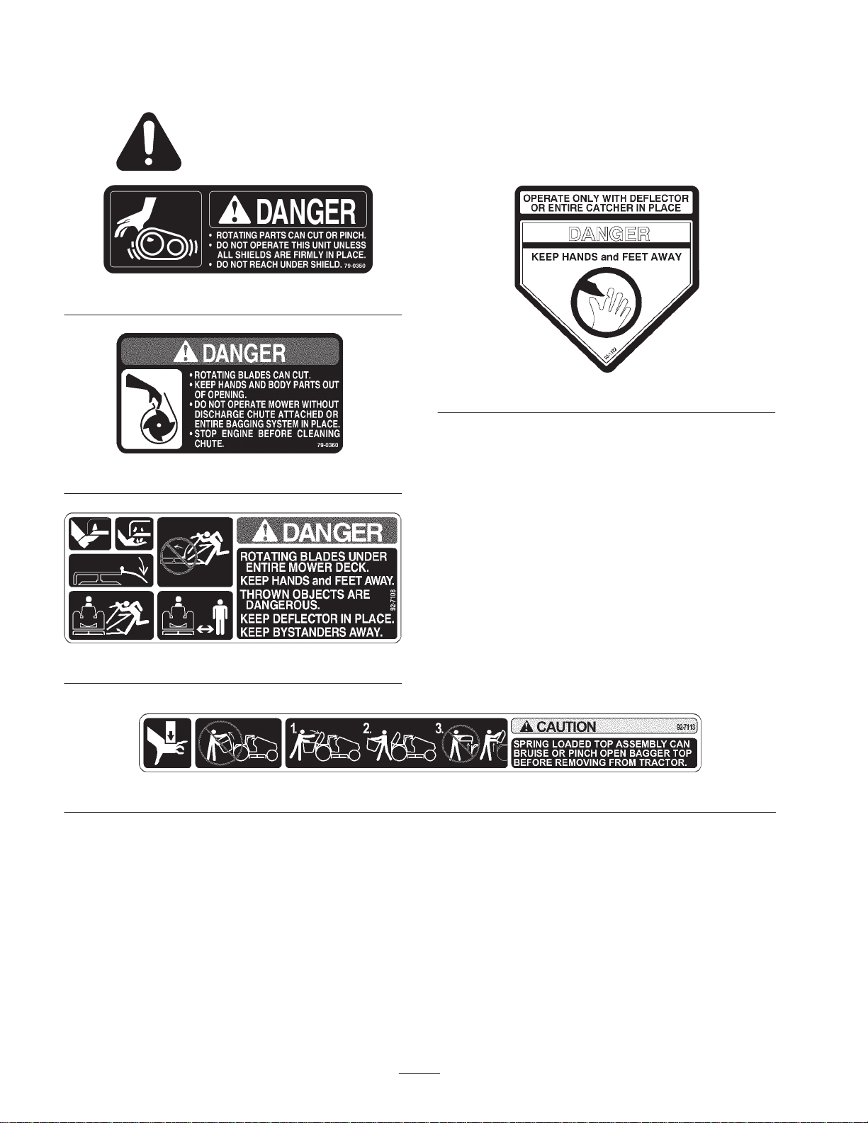
1. Remove the grass deflector from the mower (Fig. 3).
2. Remove the belt cover from the right side (Fig. 3).
Note: Save all parts and hardware for use when
converting the mower to side discharge mode.
1. Remove the bolt(s) and nut(s) at the end of the grass
plate, located inside the mower, near the back edge of
the discharge opening (Fig. 4). Discard this hardware.
2. Find the appropriate grass baffle (Fig. 4).
3. Install the grass baffle tight against the grass plate with
top edge up against inside of mower.
4. For 42 inch mowers, secure the grass baffle with a
carriage bolt (3/8 x 1 inch), washer (3/8 inch) and a
locknut (3/8 inch) (Fig. 4).
7
Page 8
3
3
1
4
2
5
1
m–6704
3
Figure 4
1. Grass plate
2. 42 inch grass baffle
3. Bolt, 3/8 x 1 inch
4. Locknut, 3/8 inch
5. Washer, 3/8 inch
5. Rotate the blade and check for clearance with the grass
baffle. If necessary adjust the baffle so blade does not
hit the grass deflector.
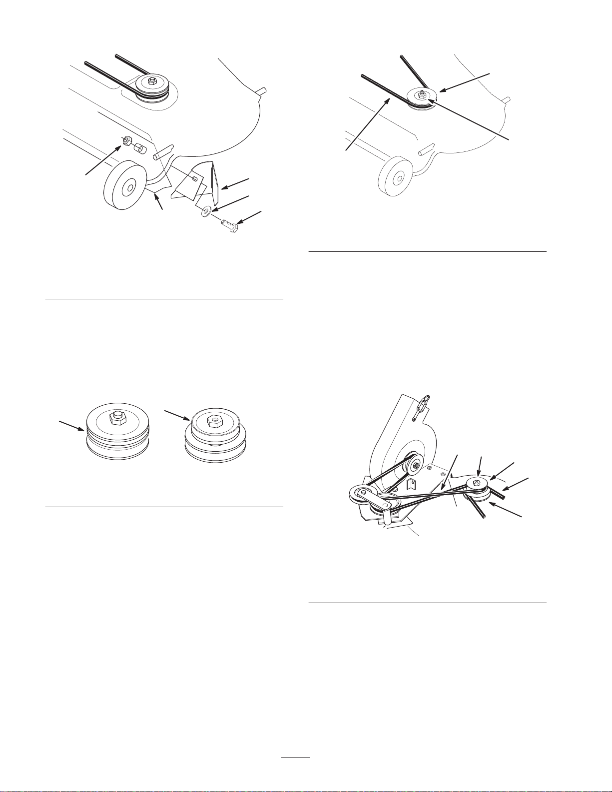
Installing the Blower Drive Pulley
1. Select the correct pulley shown in figure 5.
2
1
m–6685
Figure 5
1. 42 inch pulley 2. 48 inch pulley
m–3301
Figure 6
1. Mower belt
2. Nut and lock washer
3. Single pulley
4. Slide the new double pulley onto the spindle shaft with
the word Top, stamped into largest pulley, facing up.
Secure with previously removed lock washer
(5/8 inch) lock washer and nut (5/8 inch) (Fig. 7).
5. Tighten the nut to 50–75 ft–lb (68–101 Nm).
6. Install the existing mower belt onto the bottom pulley
(Fig. 7).
Note: Check that the mower belt is properly located on
the idler and pulleys.
4
2
1
3
2. Remove the belt from the right hand spindle pulley.
3. Remove the nut and lock washer retaining the pulley
(Fig. 6). Remove the single groove pulley.
Note: Block the blade with a piece of wood to stop it from
turning while you remove the pulley nut. If the blade slips
hold the hex portion of the spindle with a wrench.
Note: When the nut is removed the shaft is free to drop
out of the spindle. Make sure to support the spindle and
blade from the bottom side.
m–4446
1. New double pulley
2. Lock washer and nut
(5/8 inch)
8
5
Figure 7
3. Mower belt
4. Blower drive belt
5. Bottom pulley
Page 9

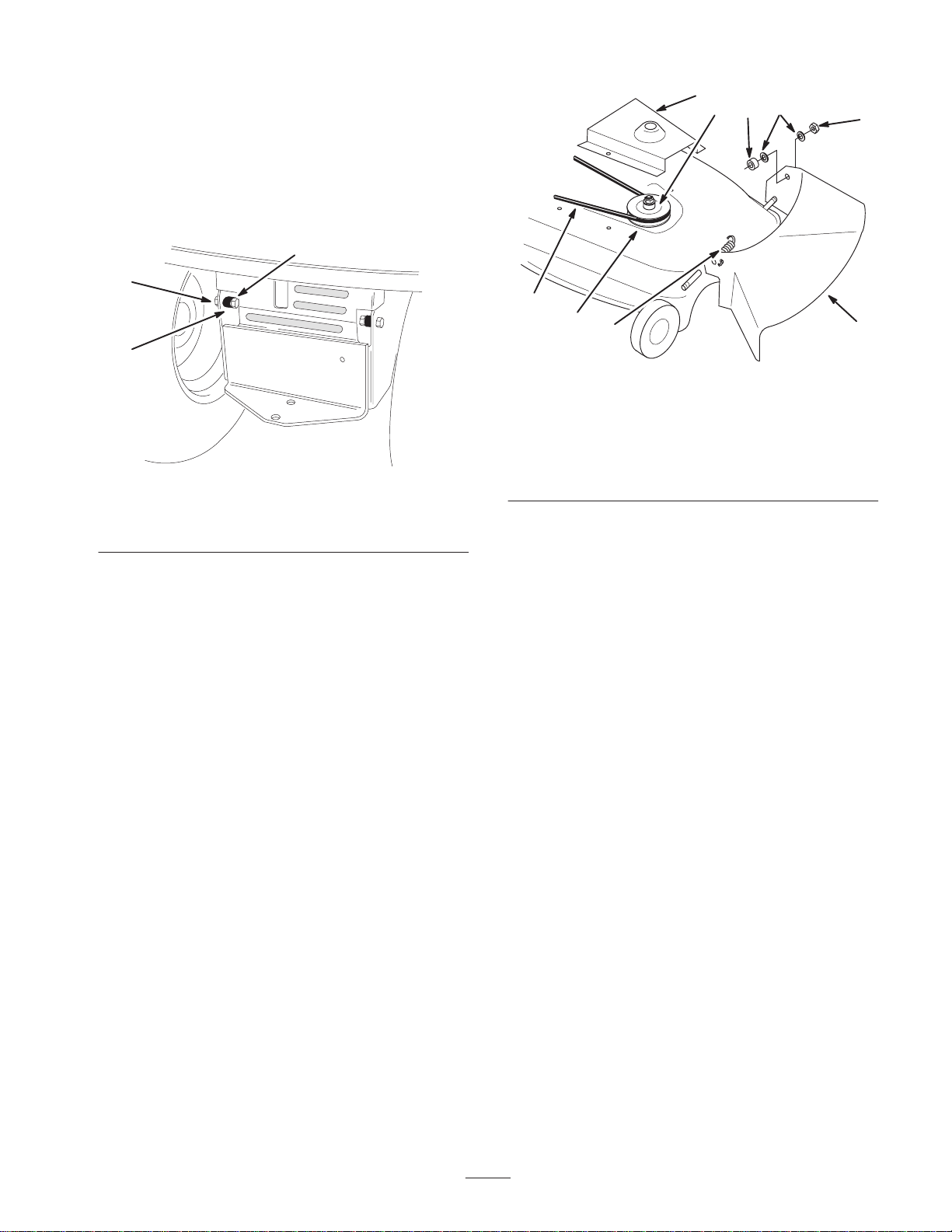
Installing the Blower Pivot Support
1. Select the proper hole in the pivot support. Refer to
Figure 8 for the correct hole.
1
2
Figure 8
1. Pivot support
2. Mounting hole for a
42 inch mower
3. Mounting hole for a
48 inch mower
2. With the correct hole, slide the pivot support over the
threaded stud welded to front of mower near the
discharge opening (Fig. 9).
3
m–6630
7
1
6
2
1494
1. Pivot support
2. Mounting hole—42 inch
3. Mounting hole—48 inch
4. Jam nut, 3/8 inch
(removed from grass
deflector)
8
Figure 9
5
3
4
5. Drill 11/32 inch diameter
hole
6. Bolt, 5/16 x 3/4 inch
7. Flange nut, 5/16 inch
8. Plastic washer (removed
from grass deflector)
3. Align the pivot support parallel with front curved edge
and tight against top of mower (Fig. 9). Clamp in this
position.
4. Drill a 11/32 inch diameter hole into the top of the
mower using the pivot support as a template.
5. Secure the pivot support to the mower with a bolt
(5/16 x 3/4 inch), through from the underside of the
mower, and a flange nut (5/16 inch) (Fig. 9).
6. Install the jam nut (3/8 inch) (removed from the grass
deflector) snug onto the stud. Do not overtighten the
jam nut.
Installing the Height–of–cut Lever on
42 inch Mowers Only
Install a new height–of–cut lever on 42 inch mowers only.
1. Remove the cotter pin and washer from the rear
adjustable link (Fig. 10).
2. Remove the rear wheel bracket from the mower
(Fig. 10).
3. Slide the rear wheel assembly to the right, towards the
side discharge side (Fig. 10).
4. Remove the existing height–of–cut lever and spring
from the mower (Fig. 10).
5. Install the new height–of–cut lever and existing spring
to the wheel assembly (Fig. 10).
6. Slide the rear wheel assembly to the left, installing the
height–of–cut lever into the height–of–cut bracket
(Fig. 10).
7. Install the cotter pin and washer to the rear adjustable
link (Fig. 10).
8. Install the rear wheel bracket to the mower (Fig. 10).
9
Page 10

7
m–6646
4
3
5
9
Figure 10
1. New height–of–cut lever
2. Spring
3. Washer
4. Cotter pin
5. Rear wheel bracket
Assembling the Blower
1
6. Rear wheel assembly
7. Rear adjustable link
8. Side discharge
9. Height–of–cut bracket
2
8
9
7
5
2
6
8
3
4
4
1
3
1496
Figure 12
1. Bolt, #10 x 3/4 inch
2. Spring
3. Nut #10
4. Washer #10
5. Latch
6. Bolt, 1/4 x 3/4 inch
7. Washer 1/4 inch
8. Lock nut 1/4 inch
9. Blower assembly
1. Install the long hook end of the tension spring and a
nut (#10) onto a bolt (#10 x 3/4 inch). Thread the nut
within an 1/8 inch (3 mm) from the head of the screw
to allow space for the spring to rotate freely (Fig. 12).
2. Slide a washer (#10) onto the screw and insert it
through the blower housing. Install a second washer
(#10) and nut (#10) onto the bolt (Fig. 12).
3. While holding the first nut, tighten the second nut so
that the assembly is tight against the plastic housing.
4. Select the appropriate latch. Refer to Figure 11 for the
correct latch.
2
m–6669
1
Figure 11
1. 42 inch mower latch 2. 48 inch mower latch
Assembling the Bagger Cover
1. Slide the threaded end of the indicator rod through
2 clips, the rubber seal, and the slot in the cover
(Fig. 13).
2. Secure the clips to the cover with 2 pan head screws
(1/4 x 5/8 inch) and 2 locknuts (1/4 inch) (Fig. 13).
3. Thread the jam nut and handle completely onto the
threaded end of the indicator rod.
4. Rotate the handle so that the decal can be read from
the operators position, then tighten the jam nut
(Fig. 13).
5. Hook the spring into the hole in the latch and mount
the latch to the blower housing with a bolt (1/4 x
3/4 inch), washer (1/4 inch), and locknut (1/4 inch)
(Fig. 12). Leave the nut loose enough so that the latch
pivots freely.
10
Page 11

6
5
1
1
4
Figure 13
1. Indicator r o d
2. Clips
3. Pan head screw, 1/4 x
5/8 inch
4. Lock nut, 1/4 inch
5. Jam nut, 1/4 inch
6. Handle
5. Mount the frame hinge to the cover with the 2 bolts
(1/4 inch) attached to it. Secure it with 2 locknuts
(1/4 inch) (Fig. 14).
1
2
1370
3
2
4
2
5
3
6
m–1981
Figure 15
1. Discharge tube
2. Tube center hole
3. Knob
4. Washer, 1/4 inch
5. Screw, #10 x 5/8 inch
6. Cut off 2–3/4 inches
(70 mm)
Installing the Vac-Bagger
Mounting the Blower
1. Insert the pivot pin on blower into the pivot support
bracket on the mower (Fig. 16).
2
3
1374
Figure 14
1. Frame hinge
2. Bolt, 1/4 inch (attached)
3. Lock nut, 1/4 inch
Assembling the Discharge Tube
1. Cut 2-3/4 inches (7 cm) off the bottom of the discharge
tube (Fig. 15).
2. Attach the knob to the center hole in the discharge
tube and secure with a washer (7/32 inch) and screw
(#10 x 5/8 inch) (Fig. 15).
1
2
1838
Figure 16
1. Pivot pin 2. Pivot support bracket
2. With the blower swung out in the open position, install
the blower drive belt between the idler pulley bracket
and pulleys. Then loop the belt around the blower
pulley (Fig. 17).
11
Page 12

3. Install the blower drive belt around the top pulley
(Fig. 17).
1. Mount the belt cover bracket into the holes used by the
original cover with 2 thread forming flange screws
(1/4 x 1/2 inch) (Fig. 19).
1
3
2
m–4446
Figure 17
1. Idler pulley bracket and
pulley
2. Top side of belt against
bottom pulley
3. V–side of belt into top
pulley
4. With the belt installed, swing the blower toward the
mower until the blower latch locks over the pin at the
back of the mower (Fig. 18).
1
2
1
2
m–6642
Figure 19
1. Belt cover
bracket—42 inch
2. Flange head, 1/4
x1/2 inch, thread forming
Note: Center the slots of cover bracket before tightening
the flange screws.
2. Mount the belt cover loosely to the outside of the belt
cover bracket and the top of the mower using 3 flange
screws (1/4 x 1/2 inch) (Fig. 20).
Note: Do not tighten the screws as an adjustment must be
made later.
2
1
2
1840
Figure 18
1. Blower latch 2. Pin
Installing the Belt Cover on 42 inch
Mowers
A belt cover and bracket are needed for a 42 inch mower.
2
m–6644
Figure 20
1. Belt cover—42 inch 2. Flange screws, 1/4 x
1/2 inch, thread forming
12
Page 13

Installing the Belt Cover on 48 inch
Mowers
1. Mount the belt cover bracket into the holes used by the
original cover with 2 thread forming flange screws
(1/4 x 1/2 inch) (Fig. 21).
2 & 3
1
4
2
1
2
m–6643
Figure 21
1. Belt cover
bracket—48 inch
2. Flange head,
1/4 x1/2 inch, thread
forming
2. Mount the belt cover loosely on top of the mower with
3 flange screws (1/4 x 1/2 inch) (Fig. 22).
Note: Do not tighten the screws as an adjustment must be
made later.
1
2
2
3
2
1997
Figure 23
1. Blower belt cover
2. Bolt, 1/4 x 5/8 inch
3. Lock nut, 1/4 inch
4. Mower belt cover
2. Adjust the blower belt cover so that the L brackets rest
on pulley plate. Tighten the blower belt cover
mounting screws (Fig. 24).
4
1
3
2
m–5083
Figure 24
1. Blower belt cover
2. Pulley plate
3. L brackets
4. Front wheel
m–6645
Figure 22
1. Belt cover—48 inch 2. Flange screws, 1/4 x
1/2 inch, thread forming
Installing the Blower Belt Cover
1. Mount the blower belt cover using 2 bolts (1/4 x
5/8 inch) and 2 locknuts (1/4 inch) (Fig. 23).
Note: Tighten the locknuts slightly so light drag is felt on
the belt cover when tilted upward. The cover must close
freely when assembled.
3. Tighten the mower belt cover mounting screws
(Fig. 20 and 22).
4. Install the mower to the tractor. Refer to Installing the
Mower in the mower Operator ’s Manual.
Installing the Bagger Assembly and Bags
1. Slide the bottom of the quick-attach bracket down into
the hole in the hitch and hook the notches onto the
spacers located inside the tractor frame (Fig. 25).
2. Slide the cotter pin through the hole at the bottom of
the quick-attach bracket (Fig. 25).
13
Page 14

3
5. Install the bags by sliding the bag frame hooks onto
the retaining brackets (Fig. 27).
1
2
4
Figure 25
1. Quick-attach bracket
2. Hole in hitch
3. Spacers
4. Hair pin cotter
3. Tip the tractor seat forward.
4. With the lid in the open position carefully lift the
bagger top and slide it onto the quick attach bracket
(Fig. 26).
1
2
3
1
2267
2
1373
Figure 27
1. Bag frame hook 2. Retaining bracket
6. Lower the bagger top onto the bags. Then push down
on both bag retainer handles until they lock onto the
bag frame (Fig. 28).
1
Figure 26
1. Bagger top 2. Quick attach bracket
Caution
If you remove the bagger top when it is closed (in
the down position), the top may suddenly fly open
and you or someone may be bruised, pinched, or
injured.
Always open (raise) the bagger top before you
remove or install it on the quick-attach bracket.
1372
2
Figure 28
1. Bagger t o p 2. Bag retai n e r handles
Installing the Discharge Tube
1. Move the tractor seat to its normal position.
2. Insert the upper end of the discharge tube into the
bagger top. Slide the lower end of the discharge tube
over the blower opening (Fig. 29).
3. Hook the rubber latch over knob (Fig. 29).
14
1376
Page 15

1
2
3
1847
Figure 29
1. Discharge tube
2. Rubber latch
3. Knob
Installing the Mower Counterweight
1. Position the mower counterweight on the left–hand
side of the mower so that the it fits snuggly against the
side of the mower (Fig. 30).
2. Using a punch in the holes of the counterweight, mark
the location for drilling 2 holes (13/32 inch dia.).
Remove the counterweight and drill the holes.
3. Secure the counterweight to the top of the mower with
2 bolts (3/8 x 2–1/4 inch), 4 flat washers (3/8 inch),
and 2 locknuts (3/8 inch).
1
Note: An extra decal is included with the bagger because
the counterweight covers the original decal.
4. Clean the mower surface and place the decal on the
mower deck, near the counterweight, between the
washout port and the belt cover.
5. Check the side to side level of the mower at the
desired cutting height. Due to varying conditions, it
may be necessary to level the mower after installing
the vac bagger. If so, refer to Leveling the Mower Side
to Side in mower Operator ’s Manual.
Removing the Vac Bagger
Danger
If you operate mower without both grass bags
installed or with the discharge tube removed, you
and others may be injured by thrown debris
or cut by the blade.
• Always operate the mower with either the
complete grass catcher mounted in place or
use the mower to side discharge.
• Make sure that the spring-loaded grass
deflector is in the down position.
Removing the Discharge Tube
1. Unhook the rubber latch from the knob (Fig. 31).
7
6
1. Locknut 3/8 inch
2. Flat washer, 3/8 inch
3. Counterweight
4. Bolt, 3/8 x 2–1/4 inch
2
5
Figure 30
5. Danger decal
6. Washout port
7. Belt cover
2
4
m–3687
2. Slide the lower end of the discharge tube off the
blower discharge opening (Fig. 31). Pull the upper end
of discharge tube out of bagger top.
3
1
2
1847
Figure 31
1. Rubber latch 2. Knob
15
Page 16

Removing the Bagger
1. Tip the tractor seat forward.
2. Raise the bagger top and remove the grass bags from
the bag frame (Fig. 32).
1
4. Remove the hairpin cotter and slide the bottom of the
quick-attach bracket up out of the hole in the hitch and
unhook it from the spacers located inside the tractor
frame (Fig. 34).
3
2
Figure 32
1. Bagger t o p 2. Bag retainer handles
Caution
If you remove the bagger top when it is closed (in
the down position), the top may suddenly fly open
and you or someone may be bruised, pinched, or
injured.
Always open (raise) the bagger top before you
remove or install it on the quick-attach bracket.
3. With the lid in the open position, carefully lift the
bagger top and slide off the quick-attach bracket
(Fig. 33).
1376
1
3
2
4
2267
Figure 34
1. Quick-attach bracket
2. Hole in hitch
3. Spacers
4. Hair pin cotter
5. Move the tractor seat to its normal position.
Removing the Blower Belt Cover
1. Remove the blower belt cover by removing the
2 locknuts (1/4 inch) and 2 bolts (1/4 x 5/8 inch)
(Fig. 35).
Note: Save all parts and hardware for use when installing
the blower.
1
2 and 3
1
2
Figure 33
1. Bagger top 2. Quick-attach bracket
1. Mower belt cover
2. Bolt 1/4 x 5/8 inch
(16 mm)
16
3
2
1997
Figure 35
3. Lock nut 1/4 inch
Page 17

Removing the Mower Belt Cover
1. Remove the mower belt cover from the right side
pulley (Fig. 36). Save the mounting hardware.
1
m–6644
2
m–6645
Figure 36
1. Belt cover–42 inch 2. Belt cover–48 inch
Removing the Blower from the Mower
1. Open the latch and swing the blower out away from
the mower, remove the blower belt from the double
pulley (Fig. 37).
1
2
1838
Figure 38
1. Pivot pin 2. Pivot support
Removing the Blower Pivot Support
1. Remove the pivot support from the mower (Fig. 39).
Note: Save all parts and hardware for use when installing
the blower.
4
1
1
m–4446
Figure 37
1. Double pulley
2. Remove the blower by lifting the pivot pin out of the
pivot support (Fig. 38).
3
5
2
1494
Figure 39
1. Pivot support
2. Nut
3. Bolt
4. Flange nut
5. Plastic washer
Installing the Belt Cover and Grass
Deflector
Note: Always install the grass deflector when changing to
the side discharge mode.
17
Page 18

Danger
Without the grass deflector, discharge cover, or
complete grass catcher assembly mounted in
place, you and others are exposed to blade contact
and thrown debris. Contact with rotating mower
blade(s) and thrown debris will cause injury or
death.
• Never put your hands or feet under the mower.
• Never try to clear discharge area or mower
blades unless you move the PTO to Off and
rotate the ignition key to Off. Also remove the
key and pull the wire off the spark plug(s).
1. Install the grass deflector onto the mower with saved
hardware (Fig. 40).
2. Install the original belt cover onto the mower with
saved hardware (Fig. 40).
2
7
4
8
1
2
7
3
2
6
5
Figure 41
1. Locknut 3/8 inch
2. Flat washer, 3/8 inch
3. Counterweight
4. Bolt, 3/8 x 2–1/4 inch
6
5. Danger decal
6. Washout port
7. Belt cover
4
m–3687
3
5
9
Figure 40
1. Grass deflector
2. Belt cover
3. Blade drive belt
4. Nut and lock washer
5. Single pulley
6. Jam nut, 3/8 inch
7. Rubber bushing
8. Plastic washers
9. Torsion spring
Removing the Mower Counterweight
1. Remove the bolts securing the counterweight to the
top of the mower (Fig. 30).
2. Remove the counterweight and save for use when
installing the bagger.
1
1836
Leveling the Mower
Level the mower when the blower and counterweight are
removed. Refer the the mower Operator’s Manual.
Operation
Note: Determine the left and right side of the machine
from the normal operating position.
Caution
To avoid personal injury, read and follow the
statements below.
• Become familiar with all operating and
safety instructions in the operator’s manual
for your tractor and mower before using
this attachment.
• Never remove the discharge tube, bags,
bagger top, or the blower while the engine
is running.
• Always shut the engine off before clearing
an obstruction from the vac bagging
system.
• Never do maintenance or repairs while the
engine is running.
18
Page 19

Using the Full Bag Tester
Clearing Obstructions From
As grass is cut and blown into the bags, the left bag fills
first, then the right bag. If you overfill the bags, grass will
eventually plug the discharge tube or elbow.
1. Stop the tractor and apply the brake.
2. To check if both bags are full, periodically raise the
full bag tester handle (Fig. 42). If you feel resistance
as you raise the handle, the bags must be emptied
because they are full (Fig. 42).
1
2
1381
Figure 42
1. Full bag tester handle 2. Bag full
Bagger
1. Stop the tractor, shift into neutral, set the parking
brake, push the PTO control to OFF (this stops the
mower blades), turn the ignition key to OFF to stop the
engine, and remove the key from the switch.
2. Check the grass bags and empty them if they are full.
3. Remove and separate the discharge tube and blower
from the bagger top and mower. Using a stick or
similar object, carefully remove and clear the
obstruction from the mower, discharge tube, blower,
and the bagger top.
4. After you remove the obstruction, install the complete
bagger system and resume operation.
Operating and Bagging Tips
Size
Remember that the tractor is longer and wider with this
attachment installed. By turning too sharply in confined
places you may damage the attachment.
Emptying the Grass Bags
Grass bags can weigh up to 90 lb (41kg) when full. Be
careful when lifting or handling a grass bag that is full. To
empty the grass bags:
1. Stop the tractor, set the parking brake, and disengage
the power take off (PTO) by pushing the PTO control
to OFF (this stops the mower blades). Shut the engine
off before you get off the tractor.
2. Tip the tractor seat forward.
3. Pull up on both bag retainer handles until they unlock
from the bag frame (Fig. 28). Now open (raise) the
bagger top.
4. Compress debris into the bags. With both hands, lift up
on the bag and unhook it from the retaining bracket
(Fig. 27). Empty the bag. Repeat for the other bag.
5. Install the bags by sliding the bag frame hooks onto
the retaining brackets (Fig. 27).
6. Lower the bagger top onto the bags. Then push down
on both bag retainer handles until they lock on the bag
frame (Fig. 28).
7. Move the tractor seat to its normal position.
Trimming
Always trim with the left side of the mower. Do not trim
with the right side of the mower because you could
damage the bagger’s blower and discharge tube.
Cutting Height
Do not set the mower cutting height too low because long
grass surrounding the mower can prevent air from getting
under the mower and entering the bagging system. If
enough air doesn’t get under the mower, the bagging
system will plug.
Cutting Frequency
Cut the grass often, especially when it grows rapidly. You
will have to cut your grass twice if it gets excessively long
(refer to Bagging Long Grass, page 20).
Cutting Technique
For best lawn appearance, be sure to slightly overlap the
mower into the previously cut area. This helps reduce the
load on the engine and reduces the chance of plugging the
blower and discharge tube.
19
Page 20

Using Bag Liners
Bagging Long Grass
Although not required, bags may be inserted into each
grass bag a liner to collect clippings and make disposal
more convenient (Fig. 43). If you use a bag liner, remove
the filled grass bag and close the top of the liner. Then
pull the liner out the grass bag or turn the bag upside
down while holding the handle on the bottom of the grass
bag, allowing the liner to slide out.
2
1
1378
Figure 43
1. Cloth grass bag 2. Bag (liner)
Excessively long grass is heavy and may not be propelled
completely into the grass bags. If this happens, the
discharge tube and blower may plug. To avoid plugging
the bagging system, mow the grass at a high height of cut,
then lower the mower to your normal cutting height and
repeat the bagging process.
Bagging Wet Grass
Always try to cut grass when it is dry because your lawn
will have a neat appearance. If you must cut wet grass, use
the conventional side discharge feature of the mower.
Several hours later, when the clippings are dry, install the
complete bagger attachment and vacuum up the grass
clippings.
Signs of Plugging
As you are bagging, a small amount of grass clippings
normally blow out the front of the mower. An excessive
amount of clippings blowing out indicates that the bags
are full or the system is plugged.
Bagging Speed
Most often you will bag with the tractor throttle in the
Fast position and drive at a normal ground speed.
However, in extremely dry and dusty grass, you may want
to slightly reduce the throttle speed and increase the
ground speed of the tractor. The bagging system may plug
if you drive too fast and the engine speed gets too slow.
On hills it may be necessary to slow the tractor ground
speed. This helps maintain the engine speed and bagging
efficiency. Mow downhill whenever possible.
Warning
As the grass bags fill, extra weight is added to the
back of the tractor. If you stop and start suddenly
on hills, you may lose steering control or the
tractor may tip.
• Do not start or stop suddenly when going uphill
or downhill. Avoid uphill starts.
• If you do stop the tractor when going uphill,
disengage the PTO. Then back down the hill
slowly in Reverse.
• Do not change speeds or stop on slopes.
20
Page 21

Maintenance
Note: Determine the left and right side of the machine from the normal operating position.
Recommended Maintenance Schedule
Maintenance Service
Interval
After each use Clean the bagger
After the first 10
operating hours, and
monthly thereafter
Storage Service
If you leave the key in the ignition switch, someone could accidently start the engine and
seriously injure you or other bystanders.
Remove the key from the ignition and disconnect the wire from the spark plug(s) before you do
any maintenance. Set the wire aside so that it does not accidentally contact the spark plug.
Maintenance Procedure
Inspect the bagger
• Clean the bagger
• Inspect the bagger
• Belts—check for wear/cracks
• Paint chipped surfaces
Inspecting the Vac Bagger
Caution
Inspecting the Mower Blades
Attachment
Inspect the blower and bagger attachment after the first
ten hours of operation, and monthly thereafter.
1. Check the discharge tube, elbow, and the bagger top.
Replace these parts if they are cracked or broken.
2. Tighten all nuts bolts and screws.
3. Inspect the grass bags for deterioration.
Danger
You or bystanders could be severely injured by
flying debris or thrown objects that may pass
through worn or deteriorated grass bags.
• Frequently check the grass bags for holes,
rips, wear, and other deterioration. Do not
wash the grass bags.
• If the bag has deteriorated, install new
grass bags supplied by the manufacturer of
this bagger attachment.
1. Inspect the mower blades regularly and whenever a
blade strikes a foreign object.
2. If blades are badly worn or damaged, install new
blades. Refer to your tractor or mower operator’s
manual for complete blade maintenance.
Caring for the Grass Bags
1. Washing the grass bags is not recommended.
2. To prevent rapid deterioration of bag material, store
the bags so they dry completely after each use.
Cleaning the Vac Bagger
Attachment
1. After each use, remove and wash the inside and
outside of the bagger top, discharge tube, discharge
elbow, blower and the underside of the mower, using
water sprayed from a garden hose. Use a mild
automotive detergent to remove stubborn dirt.
2. Make sure you remove matted grass from all parts.
21
Page 22

3. After washing let all parts dry thoroughly. Do not wash
the grass bags.
Storage
1. Clean the bagger attachment (refer to Cleaning the Vac
Bagger Attachment, page 21).
2. Inspect the bagger attachment for damage; refer to
Inspecting the Vac Bagger Attachment, page 21.
3. Make sure the grass bags are empty and thoroughly
dry.
4. Store the machine in a clean, dry place, out of direct
sunlight. This protects the plastic parts and extends the
life of the machine. If you must store the machine
outside, cover it with a weatherproof cover.
22
Page 23

Page 24

Consumer
Riding
Products
The Toro Total Coverage Guarantee
A Two-Year Full Warranty
(Limited Warranty for Commercial Use)
Conditions and Products Covered
The Toro Company and its affiliate, Toro Warranty Company,
pursuant to an agreement between them, jointly promise to repair
any Toro Product used for normal residential purposes* if defective
in materials or workmanship. The following time periods apply
from the date of purchase:
Products
• All Products and Attachments 2 year full warranty
• 300, 400, and 5xi Series Tractors:
Frame 5 year full warranty
Front Axle 5 year full warranty
Drive Shaft (5xi Series Only) 5 year full warranty
• All Batteries 1 year full warranty
This warranty covers both the cost of parts and labor, and
transportation within a fifteen mile radius of the servicing dealer.
This warranty applies to all consumer riding products and their
attachments.
* Normal residential purposes means use of the product on the
same lot as your home. Use at more than one location is
considered commercial use, and the commercial use warranty
would apply.
Warranty Period
Limited Warranty for Commercial Use
Toro Consumer Products and attachments used for commercial,
institutional, or rental use are warranted against defects in
materials or workmanship for the following time periods from the
date of purchase:
Products
• 300, 400, and 5xi Series Tractors:
Liquid Cooled Gas Engines 1 year limited warranty
Air Cooled Gas and Diesel
Engines
All other items 1 year limited warranty
• TimeCutter Models
• All other Riding Products
Warranty Period
2 year limited warranty
30 day limited warranty
90 day limited warranty
Instructions for Obtaining Warranty Service
If you think that your Toro Product contains a defect in materials or
workmanship, follow this procedure:
1. Contact any Toro Authorized or Master Service Dealer to
arrange service at their dealership. To locate a dealer
convenient to you, refer to the Yellow Pages of your telephone
directory (look under “Lawn Mowers”) or access our website at
www.Toro.com. U.S. Customers may also call 800-421-9684
to use our 24-hour Toro dealer locator system.
2. Bring the product and your proof of purchase (sales receipt) to
the Service Dealer.
If for any reason you are dissatisfied with the Service Dealer’s
analysis or with the assistance provided, contact us at:
Customer Care Department, Consumer Division
Toro Warranty Company
8111 Lyndale Avenue South
Bloomington, MN 55420-1196
800-348-2424 (U.S. customers)
877-484-9255 (Canada customers)
Owner Responsibilities
Y ou must maintain your Toro Product by following the maintenance
procedures described in the operator’s manual. Such routine
maintenance, whether performed by a dealer or by you, is at your
expense.
Items and Conditions Not Covered
There is no other express warranty except for special emission
system coverage on some products. This express warranty does
not cover:
• Cost of regular maintenance service or parts, such as filters,
fuel, lubricants, tune-up parts, blade sharpening, brake and
clutch adjustments.
• Any product or part which has been altered or misused or
required replacement or repair due to normal wear, accidents,
or lack of proper maintenance.
• Repairs necessary due to improper fuel, contaminants in the
fuel system, or failure to properly prepare the fuel system prior
to any period of non-use over three months.
• Pickup and delivery charges for distances beyond a fifteen
mile radius from an Authorized Toro Service Dealer.
All repairs covered by this warranty must be performed by an
Authorized Toro Service Dealer using T oro approved replacement
parts.
General Conditions
Repair by an Authorized Toro Service Dealer is your sole remedy
under this warranty.
Neither The Toro Company nor Toro Warranty Company is liable
for indirect, incidental or consequential damages in connection
with the use of the Toro Products covered by this warranty,
including any cost or expense of providing substitute equipment or
service during reasonable periods of malfunction or non-use
pending completion of repairs under this warranty.
Some states d o n o t a l l o w exclusions of incidental or consequential
damages, or limitations on how long an implied warranty lasts, so
the above exclusions and limitations may not apply to you.
This warranty gives you specific legal rights, and you may also
have other rights which vary from state to state.
Countries Other than the United States or Canada
Customers who have purchased Toro products exported from the United States or Canada should contact their Toro Distributor (Dealer)
to obtain guarantee policies for your country , province, or state. If for any reason you are dissatisfied with your Distributor’s service or
have difficulty obtaining guarantee information, contact the Toro importer. If all other remedies fail, you may contact us at Toro Warranty
Company.
Part No. 374-0045 Rev. A
 Loading...