

Page 1

FORM NO. 3321-810
Collector Drive
for
44’’ Mower
Model No. 79455-9900001 & Up
Operator’s Manual
IMPORTANT: Read this manual, and your tractor manual, carefully.
They contain information about your safety and the safety of others.
Also become familiar with the controls and their proper use before you
operate the product.
Ce
INTERNATIONAL ENGLISH (GB)
Page 2

Introduction
We want you to be completely
satisfied with your new product, so
feel free to contact your local
Authorized Service Dealer for help
with service, genuine replacement
parts, or other information you may
require.
The warning system in this manual
identifies potential hazards and has
special safety messages that help
you and others avoid personal injury,
even death. DANGER, WARNING
and CAUTION are signal words used
to identify the level of hazard.
However, regardless of th e hazard,
be extremely careful.
Whenever you contac t your
Authorized Service Dealer or the
factory, always know the model of
your product. This number will help
the Service Dealer or Service
Representative provide exact
information about your specific
product.
1
DANGER signals an extreme hazard
that will cause serious injury or death
if the recommended precautions are
not followed.
WARNING signals a hazard that
may cause serious injury or death if
the recommended precautions are
not followed.
CAUTION signals a hazard that may
cause minor or modera te injury if the
recommended precautions ar e not
followed.
Two other words are also used to
highlight information. “Important”
calls attention to special mechanical
information and “Note” emphasizes
general information worthy of special
attention.
1. Model and Serial Number Plate
For your convenience, write the
product model and serial numbers in
the space below.
Model No:_____________________
Serial No.:_____________________
The left and right side of the machine
is determined by sitting on the seat
in the normal operator’s position.
Page 3

Contents
Page
Safety and Instruction Decals.............................................................. 2
Installation........................................................................................... 3
Loose Parts............................................................................... 3
Mower Preparation ................................................................... 4
Leveller Stopper & Idler Mounting Bracket Installation ............. 5
Idler & Drive Belt Installation..................................................... 6
Baffle Installation ...................................................................... 6
Mower Installation..................................................................... 7
Boot Installation........................................................................ 7
Operation............................................................................................. 8
Maintenance........................................................................................ 8
Troubleshooting................................................................................... 8
___
1
Page 4
Safety
_______________________________________________________
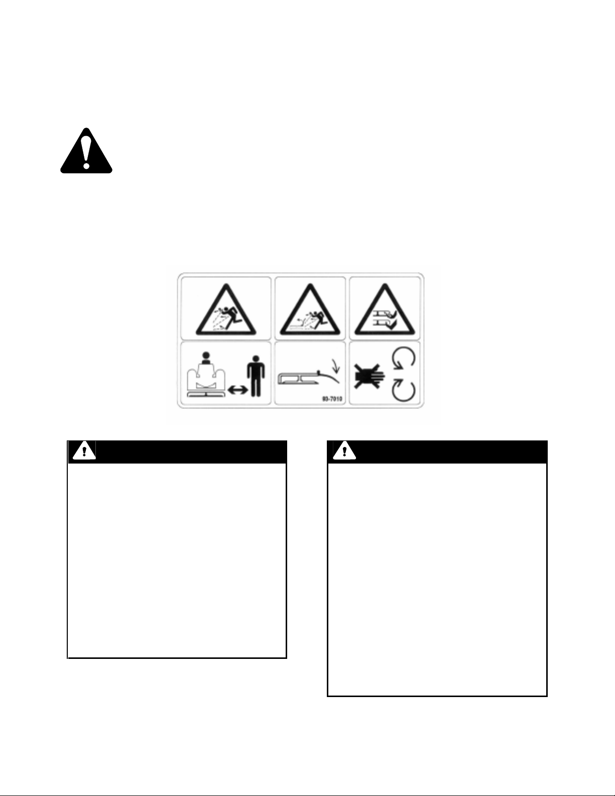
Safety Decals and Safety Instructions
Safety decals and instructions are easily visible to the operator and are located
near any area of potential danger. Replace any decal that is damaged or lost.
(1) ON BOOT BRACKET
(Part No. 93-7010)
DANGER
POTENTIAL HAZARD
• Without the discharge chute or
complete grass catcher assembly
mounted in place, you and others
are exposed to blade contact and
thrown debris.
WHAT CAN HAPPEN
• The rotating mower blade will throw
debris through the boot in all
directions and may cause injury or
death.
HOW TO AVOID THE HAZARD
• Do not cut grass with the boot on
mower if the collector & suction
tube are not in place.
___
2
DANGER
POTENTIAL HAZARD
• Rotating V-belt can cut off fingers,
hands or other body parts and
throw objects
WHAT CAN HAPPEN
• This V-belt may get tangled with the
mower V-belt & destroy both belts
or get caught on mower spindle and
be spun around giving a whip like
effect causing injury or death.
HOW TO AVOID THE PROBLEM
• Do not run the mower if the
collector drive V-belt is not properly
installed in its place on the jack
shaft’s top pulley located on the left
side of tractor rear axle. Either fully
install the V-belt or fully remove .
Do not run if partially installed.
Page 5

Installation
Loose Parts
Note: Use the chart below to identify parts used for assembly.
DESCRIPTION QTY. USE
Boot Assembly 1 Install on mower under discharge chute.
Double Idler Assembly 1 Install on top of mower.
V-Belt 1 Install on pulley.
Double pulley 1 Install on right side mower spindle.
Idler Arm 1 Replace the one on mower.
Spacer 1 Install on leveller shaft.
Idler Mounting Bracket 1 Install on top of mower.
Stopper 2 Install on top of mower.
Mower Baffle 1 Install under mower.
Mower Baffle 1 Install under mower.
Mower Baffle 1 Install under mower.
Leveller Outside 1 Replace one on mower.
Leveller Inside 1 Replace one on mower.
Hardware Bag 1 Parts installation.
Operators Manual 1 Read before operation.
___
3
Page 6

Installation
_____________________________
Mower Preparation
Remove mower from tractor if installe d. Refer
to Operators Manual, section: Removing
Mower.
1. Remove the belt guard on top of the
right side spindle (fig. 1).
2. Remove the V-belt (fig. 1).
3. Remove the right side spindle pulley by
unscrewing the spindle nut (fig. 1).
1
4
2
3
2
1
Figure 2
1. Double pulley 2. Spindle nut
5. Remove the idler arm from mower and
idler and replace with the one supplied in
kit. Reinstall as dismounted (fig. 3).
6. Reinstall the mower belt as shown in
Fig. 3. Be sure to install the belt on the
lower mower deck pulley and on the
lower spindle pulley (right hand side).
Figure 1
1. Belt guard 3. Spindle pulley
2. V-belt 4. Spindle nut
4. Install the double pulley on spindle.
Secure with lockwasher and nut. Tighten
the nut to 50 – 75 lbs.- ft. (68 – 101 Nm)
(fig. 2).
______
4
2
1
3
4
Figure 3
Top View
1. Mower belt 3. Idler arm
2. Mower deck pulley 4. Spindle pulley
Page 7

Installation
Leveller Stopper & Idler
Mounting Bracket Installation
1. Remove the two flat leveller bars on right
side and the rear leveller shaft from left
leveller bars by removing bolts, pins &
washers (fig. 4).
2. Remove the locking collar (fig. 4).
3. Remove the eye bolt by disconnecting
the trunnion (fig. 4).
4. Remove both bracket guides (fig. 4).
7
5. On left side reinstall the bracket guide
but with the leveller stopper underneath
using the same bolt and nut (fig. 5).
6. On right side install the idler mounting
bracket with the leveller stopper
underneath using the same bolts and
nuts. Do not tighten yet (fig. 5).
3
2
1
1
6
4
5
3
1
2
Figure 4
1. Outside right leveller 4. Eye bolt
2. Inside right leveller 5. Locking collar
3. Trunnion 6. Leveller shaft
7. Bracket guide
Figure 5
1. Leveller stopper 3. Bracket guide
2. Idler mounting bracket
____
5
Page 8

Installation
Idler & Drive Belt Installation
7. Flip leveller shaft 180° and reinstall to
left leveller bar. Shaft must be flipped to
allow space for collector belt (fig. 6).
8. Slide the spacer on the leveller shaft on
the right side (fig. 6).
9. Reinstall the eye bolt and trunnion as
dismounted but on the other side of the
flat bar (right side) as shown (fig. 6).
10. Slide the locking collar on the right side
against the eye bolt and secure in place
(fig. 6).
11. Install the leveller bars supplied with kit
in the same fashion as original bars
were mounted, the raised portion
upwards (fig. 6).
1. Install the double idler assembly on the
mounting bracket. Secure with cotter
pin. Align the support rod on top of the
inside leveller bar as shown. Tighten the
mounting bracket securely (fig. 7).
3
4
2
1
Figure 7
1. Idler mounting bracket 3. Cotter pin
2. Double idler asembly 4. Support rod
2. Route the V-belt under the leveller bars
to the top pulley of the blade spindle and
in front of idler pulleys, then towards the
back (fig. 8).
7
6
4
3
5
Figure 6
1. Outside right leveller 5. Eye bolt
2. Inside right leveller 6. Spacer
3. Locking collar 7. Leveller shaft
4. Trunnion
2
1
2
4
3
1
Figure 8
1. V-belt 3. Top pulley
2. Leveller bar 4. Idler pulley
5. Double pulley
______
6
Page 9

Installation
Baffle Installation
1. Flip the mower upside down. Assemble
short & long baffles together with 5/16 x
3/4” (19mm.) carriage bolts (fig. 9).
2. Assemble baffle assembly to deck using
3/8 x 3/4” (19mm.) carriage bolts
supplied and the deck bolts in place.
3. Using the longest baffle as a template,
drill a hole 0.406 (10mm.) (item 4)
through the deck (fig. 9). Secure using
3/8 x 3/4” (19mm.) carriage bolt (fig. 9).
4. Install end baffle using hex bolt 5/16 x
3/4”(19mm.) (fig. 9).
5. Place the mower uprite. Verify if
everything is well installed and tighten all
bolts securely.
3
2
Mower Installation
1. Install the mower on tractor as per
Mower Operator Manual. Install the
collector drive belt to the top pulley on
the jack shaft located under the left rear
axle. If not installed, see: Quiet
Collector Operator Manual for
instructions. Be sure the belt is properly
routed on all idlers and pulleys before
operation.
2. Reinstall the belt guard on right side
spindle pulley using two spacers, hex
bolts 1/4 x 2” (51mm.) flat and lock
washers. Tighten securely (fig. 10).
2
3
4
5
1
Figure 9
1. Long baffle 3. End baffle
2. Short baffle 4. Hole location
1
4
Figure 10
1. Belt guard 4. Flat washer 5/16 dia.hole
2. Hex bolts 1/4 x 2” 5. Spacers
3. Lock washers 1/4”
____
7
Page 10

Installation
Boot Installation
1. Install the boot on mower by lifting the
mower discharge chute (do not remove
it) and introducing the boot bracket
between the chute and the mower deck.
Release the chute. It should lock the
boot in place behind the bolt head. If
the bolts are not positioned correctly to
lock the boot in place, loosen the bolts,
slide them to the correct position so that
the chute locks the boot in place.
Tighten the bolts. The boot must be
touching the mower snuggly (fig. 11).
See Collector set up for continued
instructions.
4
5
2
1
Figure 11
1. Boot 4. Channel
2. Mower 5. Bolt
3. Discharge chute
3
____
8
Page 11

Operation
Read:
Mower and Collector Operator’s Manuals operations sections.
The operation of mower itself is the same with or without the collector drive.
Baffles, idlers and belt can be left in place for side discharge operation.
Maintenance
Read:
Mower and Collector Operator’s Manuals, maintenance sections.
The maintenance on mower is the same with or without the collector drive except for the extra belt
and idler inspection.
Troubleshooting
PROBLEM POSSIBLE CAUSES CORRECTIVE ACTION
Belt comes off pulley or slips Belt tension is incorrect Verify if the V-belt idler
tensioner slides freely.
Apply oil if necessary.
Verify if the spring is not
damaged.
Install a new belt.
____
9
 Loading...