

Page 1

FORM NO. 3321–112
Z – Master
Collection System
for
OUT FRONT Z – 48” MOWER
Model No. 79434– 890001 & Up
Operator’s Manual
IMPORTANT: Read this manual carefully. It contains information about your
safety and the safety of others. Also become familiar with the controls and
their proper use before you operate the product.
Page 2
Introduction
We want you to be completely satisfied with your
new product, so feel free to contact your local
Authorized Service Dealer for help with service,
genuine replacement parts, or other information you
may require.
Whenever you contact your Authorized Service
Dealer or the factory, always know the model and
serial numbers of your product. These numbers will
help the Service Dealer or Service Representative
provide exact information about your specific
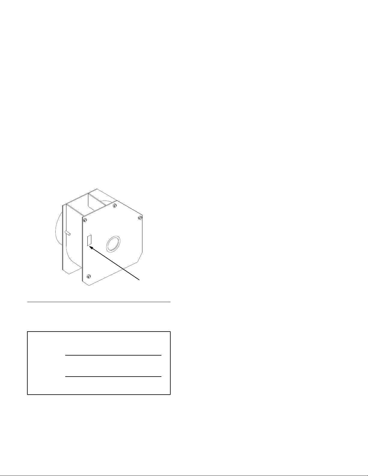
product. You will find the model and serial number
plate located in a unique place on the product as
shown below.
The warning system in this manual identifies
potential hazards and has special safety messages that
help you and others avoid personal injury, even death.
DANGER, WARNING and CAUTION are signal
words used to identify the level of hazard. However,
regardless of the hazard, be extremely careful.
DANGER signals an extreme hazard that will cause
serious injury or death if the recommended
precautions are not followed.
WARNING signals a hazard that may cause serious
injury or death if the recommended precautions are
not followed.
CAUTION signals a hazard that may cause minor or
moderate injury if the recommended precautions are
not followed.
Two other words are also used to highlight
information. “Important” calls attention to special
mechanical information and “Note” emphasizes
general information worthy of special attention.
1
1. Model and Serial Number Plate
For your convenience, write the product model and
serial numbers in the space below.
Model No:
Serial No.
The left and right side of the machine is determined
by sitting on the seat in the normal operator’s
position.
Printed in USA
The Toro Company – 1997
Page 3

Contents
Safety and Instruction Decals 2. . . . . . . . . . . . . .
Installation 3. . . . . . . . . . . . . . . . . . . . . . . . . . . . .
Loose Parts 3. . . . . . . . . . . . . . . . . . . . . . . . .
Mower Preparation 5. . . . . . . . . . . . . . . . . . .
Install Blower 6. . . . . . . . . . . . . . . . . . . . . . .
Install Hopper 9. . . . . . . . . . . . . . . . . . . . . . .
Install Wire Harness 10. . . . . . . . . . . . . . . . . .
Operation 12. . . . . . . . . . . . . . . . . . . . . . . . . . . . . .
Operating the Power Take Off (PTO) 12. . . .
Dumping the Hopper 13. . . . . . . . . . . . . . . . .
Tilting the Mower 13. . . . . . . . . . . . . . . . . . .
Page
Page
Recycler Operation 15. . . . . . . . . . . . . . . . .
Bagging Tips 16. . . . . . . . . . . . . . . . . . . . . . .
Maintenance 17. . . . . . . . . . . . . . . . . . . . . . . . . . . .
Service Interval Chart 17. . . . . . . . . . . . . . . .
Cleaning Hopper Screens 17. . . . . . . . . . . . . .
Replacing the Blower Belt 18. . . . . . . . . . . . .
Cleaning the Hopper Full Sensor 18. . . . . . . .
Greasing and Lubrication 19. . . . . . . . . . . . . .
Storage 19. . . . . . . . . . . . . . . . . . . . . . . . . . . .
Troubleshooting 20. . . . . . . . . . . . . . . . . . . . . . . . .
1
Page 4

Safety
Safety and Instruction Decals
Safety decals and instructions are easily visible to the operator and are located near
any area of potential danger. Replace any decal that is damaged or lost.
2
Page 5

Installation
Loose Parts
Note: Use the chart below to identify parts used for assembly when unit is to be installed on traction unit.
DESCRIPTION QTY. USE
Bagger baffle–left
Bagger baffle–right
Discharge baffle–left
Discharge baffle–right
Carriage bolt 5/16”–18 x 3/4” (19 mm)
Locknut 5/16”–18
Chute latch
Screw 10–24 x 1/2” (13 mm)
Locknut 10–24
Clevis pin
Hairpin cotter
Spring
Spring bracket
PTO Pulley
Key
Square head set-screw 5/16–18 x 1/2” (13 mm)
Blower belt
1
1
1
1
10
10
1
2
2
1
1
1
1
1
1
2
1
Install baffles and latch to mower
Install PTO drive pulley to PTO gearbox
Thread lock
Blower assembly
Bolt 3/8–16 x 1” (26 mm)
Bolt 3/8–16 x 2-3/4” (70 mm)
Idler assembly
Spacer
Washer 3/8” x 7/8” (9 x 22 mm)
Flange locknut 3/8–16
Spring
Bolt 5/16–18 x 1-1/4” (32 mm)
Nut 5/16–18
Flange locknut 5/16–18
Interlock switch bracket assembly
Bolt 3/8–16 x 3/4” (19 mm)
1
1
1
1
1
1
1
2
1
1
1
1
1
1
Install blower, idler and switch assemblies to
traction unit
3
Page 6

Installation
DESCRIPTION USEQTY.
Blower
Blower outlet chute
Bolt 5/16–18 x 5” (127 mm)
Flange locknut 5/16–18
Bumper
Tilt brackets
Bolt 3/8–16 x 1” (26 mm)
Flange locknut 3/8–16
Bolt 1/2–13 x 2-3/4” (70 mm)
Bolt 1/2–13 x 1-1/4” (32 mm)
Locknut 1/2–13
Gas spring
Safety clip
Ball stud
Locknut 5/16–18
Draw latch
Washer 1/2” (13 mm)
1
1
2
2
1
2
4
4
2
2
5
1
2
2
2
1
1
Assemble blower and outlet chute
Install bumper and gas spring to traction unit
Bolt 1/2–13 x 1” (26 mm)
Hopper assembly
Clevis pin 3/8 x 1” (26 mm)
Hairpin cotter–small
Wire harness
Cable ties
Buzzer
Clevis pin 3/8 x 1” (26 mm)
Hairpin cotter–small
Operator’s Manual
Parts Catalog
1
1
2
2
1
4
1
1
1
1
1
Install wire harness and buzzer
Lockout for blower belt when Recycler is
installed
Read before operating
Ordering parts
4
Page 7
Installation
Mower Preparation
Remove Recycler Baffles
1. Tilt mower into the vertical position, refer to;
Tilting the Mower, page 13.
2. Remove locknuts, carriage bolts and the
Recycler
Note: Save all hardware for use when
2
1. Recycler baffle
2. Carriage bolt
baffles from the mower (Fig. 1).
installing Recycler
3
baffles.
1
Figure 1
3. Locknut
m-3562
4. Locate the latch on top of the mower and secure
with (2) 10–24 x 1/2” (13 mm) screws, through
from the bottom of mower, and (2) 10–24
locknut (Fig. 2).
2
3
1
1. Bagger baffle
2. Locknut 3/8”
3. Carriage bolt
5/16–18 x 3/4” (19 mm)
4. Discharge baffle
3
Figure 2
4
5. Latch
6. Screw 10–24 x 1/2”
(13 mm)
7. Locknut 10–24
2
m-3544
7
5
4
6
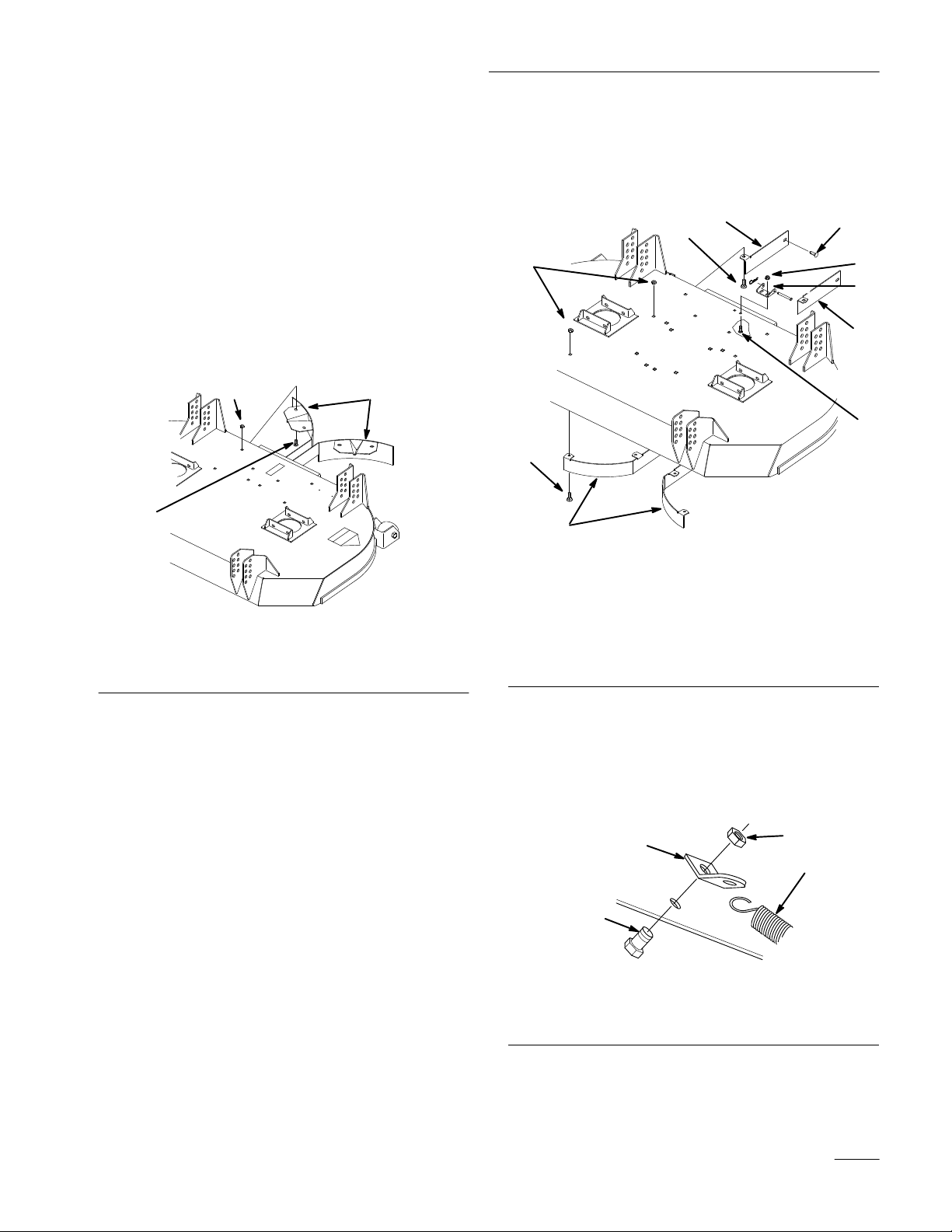
Install Bagger and Discharge Baffles,
Chute Latch and Spring
1. Locate the left and right bagger baffles inside the
mower and secure with (6) 5/16–18 x 3/4”
(19 mm) carriage bolts, through from the bottom
of mower, and (6) 5/16” locknuts (Fig. 2).
2. Locate the left and right discharge baffles inside
the mower and secure with (4) 5/16–18 x 3/4”
(19 mm) carriage bolts, through from the bottom
and inside of mower, and (4) 5/16”
locknut.(Fig. 2).
3. Mount latch on chute and hold against rear of
mower. If holes are not drilled, mark, center
punch and drill two 17/64” (7mm) holes in
mower for latch.
5. Attach spring bracket below traction unit control
plate with existing rear center bolt, down from
the top, and locknut (Fig. 3). Hook chute spring
into bracket
3
4
m-3563
2
1. Spring bracket
2. Existing bolt
1
Figure 3
3. Existing locknut
4. Spring
5
Page 8
Installation
Install Blower
For ease in performing the following steps, block the
right drive wheel, raise the rear of the traction unit,
minimum 16” (406 mm) under rear of engine carrier
frame, and block with jack stands, and remove the
left drive wheel.
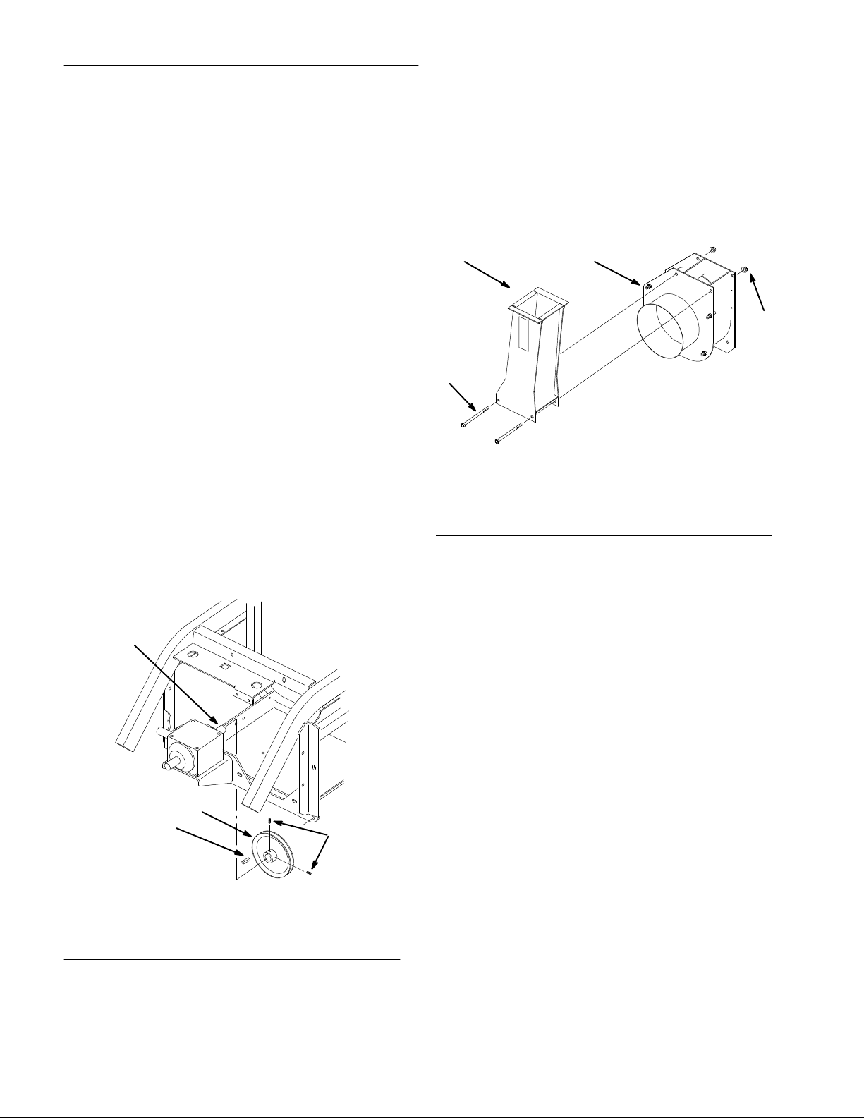
Install PTO (Power Take Off) Pulley
Note: On 25 hp models only, remove the oil
filter for clearance.
1. Apply thread lock to (2) pulley setscrews
(Fig. 4).
Note: Before installing drive pulley, bend
R–clamp holding fuel line on engine
up, to provide pulley clearance.
2. Slide key and pulley, with setscrews toward
gearbox, onto PTO gearbox rear output shaft
(Fig. 4). Do not tighten (2) setscrews at this
time.
Assemble Blower
4. Place impeller chute above blower opening with
flanges outside blower housing. Secure to
blower with (2) 5/16–18 x 5” (127 mm) bolts
and 5/16–18 flange locknuts (not shown)
(Fig. 5).
1
3
1. Chute
2. Blower housing
2
m–3540
Figure 5
3. Bolt 5/16–18 x 5”
(127 mm)
4. Flange locknut 5/16–18
4
3. Place blower drive belt around PTO pulley.
3
1
1. Pulley
2. Key
2
Figure 4
3. Gearbox rear shaft
4. Setscrew
4
m-3538
6
Page 9

Installation
Mount Blower and Idler Assemblies
Note: It may be convenient to loosen, not
remove, parking brake switch and
hydraulic oil filter brackets to ease
installation.
5. Slide blower\chute assembly up from bottom of
the machine and place against traction unit frame
(Fig. 6).
6. Place blower drive belt around PTO and blower
pulleys before bolting blower assembly to
traction unit frame (Fig. 7).
7. Install 3/8–16 x 1” (25 mm) carriage bolt in
lower right hole of rear blower flange. Secure
with a 3/8–16 flange locknut (Fig. 6).
8. Install 3/8–16 x 2-3/4” (70 mm) bolt through
lower left hole of blower rear flange (Fig. 6).
9. Slide spacer, idler assembly and 3/8” (9.5 mm)
washer onto bolt and secure with 3/8–16 flange
locknut (Fig. 6).
10. Thread 5/16–18 nut onto 5/16–18 x 1-1/4”
(32 mm) spring mount bolt and place into lower
frame hole. Secure with 5/16–18 locknut
(Fig. 6).
1
13
3
1. Blower assembly
2. Carriage bolt 3/8–16 x 1”
(25 mm)
3. Flange locknut 3/8–16
4. Bolt 3/8–16 x 2-3/4”
(70 mm)
5. Spacer
6. Idler assembly
4
2
Figure 6
12
3
7
6
5
11
10
7. Washer3/8” (9.5 mm)
8. Bolt 5/16–18 x 1-1/4”
(32 mm)
9. Nut 5/16–18
10. Locknut 5/16–18
11. Spring
12. Switch assembly
13. Bolt 3/8–16 x 3/4” (19 mm)
9
m-3539
3
8
11. Hook spring over bolt and stretch to hook on
arm of idler assembly (Fig. 6).
12. Hold switch bracket assembly to back side of
frame cross member. Insert 3/8–16 x 3/4”
(19 mm) bolt, from inside impeller chute,
through chute, frame and switch bracket. Secure
with 3/8–16 locknut (Fig. 6).
13. Tighten all mounting hardware securely.
7
Page 10

Installation
14. Using blower belt as a guide slide the PTO
pulley, in or out on gearbox shaft, to align with
blower pulley.
15. Torque setscrews to 15–18 ft.-lbs. (20–24 N
16. Pull down on idler assembly, place belt above
idler pulley and release tension Use a straight
edge to check for belt alignment.
3
2
1. PTO pulley
2. Blower pulley
Figure 7
3. Belt
4. Setscrew
4
m-3550
m)
Install Chute
19. Raise mower and slide chute into blower inlet
(Fig. 9).
20. Lower mower and slide chute forward against
rear of mower. Secure chute to rear of mower
latch with clevis and hairpin cotter pin (Fig. 9).
1
2
1. Chute
2. Hairpin cotter
1
4
3
m-3564
Figure 9
3. clevis pin
4. Blower inlet
17. Push up and hold the spring loaded idler arm,
behind blower, to relax pressure on blower belt
(Fig. 8).
18. If holes do not align, mark the idler arm hole
location onto the frame member. Center punch
and drill a 13/32” (11 mm) hole for the clevis pin
(Fig. 8).
1
2
Figure 8
1. Idler arm
2. Frame
3
m–3807
3. Mark and drill hole 13/32”
(11 mm)
8
Page 11

Installation
Install Hopper
1. Place hopper tilt brackets inside bumper with
tube weld away from the opening. Secure to
bumper with (4) 3/8–16 x 1” (26 mm) bolts and
(4) 3/8–16 flange locknuts (Fig. 10).
1
4
5
Figure 10
1. Bumper
2. Tilt bracket weld
3. Bolt 3/8–16 x 1” (26 mm)
4. Flange locknut 3/8–16
5. Adjustment slot
2. Position bumper around top rear of frame and
secure in the center with (2) 1/2–13 x 1-1/4”
(32 mm) bolts and 1/2–13 locknuts (Fig. 11).
Secure to outer holes with (2) 1/2–13 x 2-3/4”
(57 mm) bolts and 1/2–13 locknuts.
3. Install ball stud to hopper frame and traction unit
frame tab with 5/16–18 locknut (Fig. 11).
2
3
m–3803
4. Secure hopper latch to the frame with 1/2”–13 x
1” (25 mm) bolts and 1/2”–13 locknut (Fig. 12).
1
4
1. Hopper latch
2. Bolt 1/2”–13 x 1” (25 MM)
3. Washer 1/2” (13 mm)
Figure 12
4. Locknut 1/2”–13
5. Front of unit
2
5
3
m-3554
5. Place hopper assembly onto frame and align
with holes in bumper mounts. Insert (2) clevis
pins and secure with hairpin cotters (Fig. 13).
6. Adjust tilt brackets in slots (Fig. 10) so chute
opening and hopper opening align at the front.
7. Snap gas spring rod ends over ball stud at frame
and hopper. Secure with safety clips (Fig. 11).
Note: Rod end of gas spring must face the
rear and attach to the traction unit
frame.
6
1. Bumper
2. Bolt 1/2–13 x 1-1/4”
(32 mm)
3. Bolt 1/2–13 x 2-3/4”
(57 mm)
8
Figure 11
3
5
7
4. Locknut 1/2–13
5. Ball stud
6. Locknut 5/16–18
7. Gas spring
8. Safety clip
2
6
m-3513
2
1
1
3
m-3565
Figure 13
1. Hopper frame assembly
2. Clevis pin
3. Hairpin cotter
9
Page 12

Installation
Install Wire Harness
8. Unplug clutch connector from existing main
wire harness (Fig. 14). Located below and
behind muffler.
9. Insert new jumper connectors of new wire
harness between clutch connector and main wire
harness. Align connectors and push together
firmly so latches lock (Fig. 14).
1
2
4
3 m-3566
3
11. Route new wire harness along left horizontal
frame member and secure to existing wire
harness with wire ties to keep harness away from
engine.
12. Loosen left console clamp and two lower front
mounting bolts. Pull console away from left
frame member to gain access to holes in frame
and console. Route new wire harness through
holes in frame and into bottom of console
(Fig. 16).
13. Remove instrument panel and remove plug in
opening or drill a 1-1/8” (29 mm) hole for
buzzer 1-1/2” (39 mm) below hour meter.
14. Insert buzzer, from the rear, and secure with
retaining ring (Fig. 16).
15. Connect new wire harness pink lead to +
terminal and green lead to – terminal (Fig. 16).
16. Coil excess wire harness behind panel
Figure 14
1. Clutch connector
2. Main wire connector
3. New jumper connector
4. Latch
10. Route remainder of new wire harness around
back of engine to the left vertical frame member,
following main wire harness. Attach wire ties to
keep harness out of castor wheel (Fig. 15).
1
2
m-3567
1. New wire harness
2. Existing wire harness
3
Figure 15
3. Castor wheel
7
6
5
3
1
2
Figure 16
1. Console clamp
2. Front bolt
3. Hole in console
4. 1-1/8” (29 mm) Hole 1-1/2”
(39 mm) below hourmeter
8
4
9
m-3568
5. Buzzer
6. Retaining ring
7. Pink +
8. Green –
9. Wire harness
10
Page 13

Installation
2
17. Route hopper full sensor wire harness below
bumper and frame. Connect hopper full sensor
wire harness terminals to (3) round terminal of
main wire harness (Fig. 17).
IMPORTANT: Color codes may not match at
all (3) terminals and must be as follows or
diode will be damaged.
Green – Green or Grey (on some models)
Pink – Pink
Black – Black
18. Push terminals together firmly so latches lock
(Fig. 17).
19. Install wire tie around bumper to hold sensor
wire harness (Fig. 17).
3
1
4
2
20. Remove jumper wire from main wire harness
terminal and install interlock switch connector.
Align connector tab and push together firmly so
latch locks (Fig. 18).
Note: After assembly, adjustment of
magnetic switch may be required.
Bend mounting bracket, as required, to
place switch close to magnet on
bottom of hopper.
5
4
1. Jumper wire connector
2. Main wire harness
terminal
3
Figure 18
3. Switch connector
4. Tab and latch
5. Bend bracket
m-3553
1
1. Sensor wire harness
2. Round terminals
m-3570
Figure 17
3. Latch
4. Wire tie
11
Page 14

Operation
Operating the Power Take Off
(PTO)
The power take off (PTO) switch engages and
disengages power to the electric clutch.
Engaging the PTO
1. Release pressure on the traction control levers
and place in neutral (Fig. 19).
2. Release the parking brake (Fig. 19).
1
2
3
3. To engage lift cover and move the PTO switch to
the “ON” position (Fig. 20).
Disengaging the PTO
1. Closing the cover moves the PTO switch to the
“OFF”position (Fig. 20).
2
1
m-2721
Figure 20
1. PTO-Off 2. PTO-On
1. Traction control lever
2. Parking brake
m-3180
Figure 19
3. PTO-Switch
12
Page 15

Operation
Dumping the Hopper
The hopper is equipped with a hopper full sensor that
checks for a full condition. When the alarm buzzer
sounds the hopper needs to be emptied.
1. Locate the traction unit so the hopper door is
where you want to dump the clippings.
2. Move the power take off (PTO) switch to off,
move the traction controls to neutral and set the
parking brake.
IMPORTANT: The hopper is interlocked
with the engine ignition and the engine will
stop if these steps are not followed before
dumping the hopper or getting out of the seat.
3. Unhook the door latches on the rear sides and
the hopper latch on the front left side of the
hopper (Fig. 21).
4. Open the door and lift up on the hopper at the
lower front and dump the clippings (Fig. 21).
Tilting the Mower
The mower can be tilted up for ease of service or to
shorten unit length for transport and storage.
To Raise Mower
1. Turn engine off, set the parking brake and check
that PTO cover is down against footrest
(Fig. 23).
2. Remove the hairpin cotter and clevis pin from
the latch, at the rear of the mower. Slide the
chute rearward into blower inlet (Fig. 22).
Spring holds chute in place.
3
1
2
2
1. Door latch
2. Hopper latch
3
Figure 21
3. Lift here
m-3571
5. Lower the hopper and secure the door latches on
the rear sides and the hopper latch on the front
left side of the hopper (Fig. 21).
IMPORTANT: Front left latch must be
secured to prevent hopper from accidently
tilting during transport.
m-3564
1
1. Hairpin cotter
2. Clevis pin
Figure 22
3. Chute
13
Page 16

Operation
3. Lift on side of the mower to release weight on
latch pin and pull out on latch pin to release
(Fig. 23). Lower rear of mower onto anti-scalp
rollers. Repeat on the other side.
4
1
3
m-3374
1. Parking brake
2. PTO cover
2
Figure 23
3. Latch pin
4. Notch–open
To Lower Mower
1. Pull out latch pins and rotate into notch, holding
in the open position (Fig. 23). Standing in front
of the mower, pull forward on the front and
lower mower (Fig. 24).
2. Rotate latch pins into released position and lift
up on side of the mower until latch pin engages
(Fig. 23). Repeat on the other side.
3. With rear of chute inside blower housing slide
forward against rear of the mower and secure
with clevis pin and hairpin cotter (Fig. 22).
4. Standing in front of the mower, lift up and push
rearward on front to raise mower (Fig. 24). Raise
mower until it contacts stops and latch pins snap
into locked position.
1
m–3375
Figure 24
1. Mower up
14
Page 17

Operation
Recycler Operation
When operating the mower with Recycler baffles
installed you must disengage the blower drive belt.
1. Stop the engine, remove the key and disconnect
the spark plug wire(s) from the spark plug(s).
2. Remove hairpin cotter and clevis pin from outer
hole in idler arm (Fig. 25).
3. Push up on the spring loaded idler arm, behind
PTO (power take off) gearbox, to relax pressure
on blower belt (Fig. 25).
4. Align inner hole in idler arm with slot in frame
and insert clevis pin. Secure with hairpin cotter
to hold in position.
2
4
3
5. Remove the bagger and discharge baffles from
the mower and install the Recycler baffles
(Fig. 26).
1
m-3562
Figure 26
1. Recycler baffle
1. Idler arm
2. Frame slot
1
m-3548
Figure 25
3. Clevis pin
4. Hairpin cotter
15
Page 18

Operation
Bagging Tips
For best performance, regulate traction speed to keep
engine rpm high and somewhat constant. A good rule
to follow is: decrease ground speed as the load on the
cutting blade increases; and increase ground speed as
load on the blade decreases. This allows the engine,
working with the transmission, to sense the proper
ground speed while maintaining high blade tip speed,
necessary for good quality-of-cut, vacuuming action
and to throw grass into the hopper. If blower speed
drops too low, plugging may result. Refer to Cutting
Unit and Traction Unit Operator’s Manual for
operation of each.
1. Stop engine when emptying hopper to prevent
engine air intake from being clogged with
clippings.
2. Do not collect extremely long grass as the bag
will fill too quickly.
3. The grass collector hopper is designed to exhaust
air through the rear cover. This allows the hopper
to fill completely. Grass will fall through the
chute when the hopper is full. When the hopper
full buzzer sounds immediately disengage the
power take off (PTO) and empty the hopper.
Failure to empty the hopper will plug the chute
and cause clumping on the lawn. After emptying
hopper, check that grass clippings have not fallen
into chute.
4. When bagging wet, heavy grass, some clippings
may not be thrown completely through the
chute. When this happens, reduce ground speed.
5. While operating, check frequently for excessive
clippings left on turf or uncut grass. If those
conditions occur, the blower or cutting unit may
be plugged. Stop unit, disengage PTO, set
parking brake and shut of ignition. Check for
obstructions in the chute, blower or cutting unit.
Clear any obstructions using a stick or similar
tool. Check that screen in hopper is clear of
obstructions. Check blower belt for slipping.
6. Cut grass often, especially when growth is rapid.
If shorter grass is desired, cut the grass again.
Overlap swaths to produce an even cutting
pattern.
16
Page 19

Maintenance
Service Interval Chart
Each
Service Operation
Belts – check for wear/cracks X
Hopper – clean X X
Screens – clean (as required) X
Chipped Surfaces – paint X
Cleaning Hopper Screens
For best clipping collection, maximum air flow
through the hopper is required. To provide maximum
air flow, the hopper screens must be kept clean.
1. To clean the hopper screens dump the hopper to
remove grass clippings.
2. With the door open, remove the knobs at the
upper front of the hopper and slide the screens
out the rear of the hopper (Fig. 27).
Use50Hours
3. Clean the screen by brushing off with your hand,
4. Replace the screens and secure with knobs
Storage
Service
blowing with compressed air or spraying with a
stream of water.
(Fig. 27). Close and latch the hopper door.
1
Notes
2
Figure 27
1. Knob 2. Screen
m–3546
17
Page 20

Maintenance
Replacing the Blower Belt
Squealing when the belt is rotating, blower slipping
causing frequent clogging of chute and blower, frayed
belt edges, burn marks and cracks are all signs of a
worn blower belt. Replace the blower belt if any of
these conditions are evident.
1. Stop the engine, remove the key and disconnect
the spark plug wire(s) from the spark plug(s).
2. Push up on the spring loaded idler pulley behind
PTO (power take off) gearbox to relax pressure
on blower belt (Fig. 28). Lock into frame slot,
refer to (Fig. 25).
3. Remove worn blower belt.
Note: On 25hp traction units: loosen, but do
not remove, blower mounting bolts for
clearance between engine oil cooler
and blower shaft bolt so belt clears.
4. Install new blower belt around PTO gearbox and
blower pulleys. Then push up on the idler and
place belt above idler pulley (Fig. 28).
5. Check that belt aligns with PTO, blower and
idler pulleys (Fig. 28).
Cleaning the Hopper Full
Sensor
The hopper full sensor, inside the top right side of the
hopper, detects a beam of light from the transmitter to
the receiver. If the light beam is blocked the sensor
buzzer sounds. If the lenses are covered with
clippings or debris it may give false hopper full
signals and needs to be cleaned.
1. To clean the hopper full sensor dump the hopper
to remove grass clippings.
2. With the door open, wipe off the lenses of both
the transmitter and receiver with a soft cloth or
paper towel (Fig. 29).
3. To test the hopper full sensor for proper
operation turn the ignition key and PTO switch
to “ON”, but do not start the engine. Place a
piece of heavy cardboard in front of the
transmitter to block the light beam (Fig. 29). The
alarm buzzer should sound.
Note: Do not use your hand to test for proper
sensor operation as the light beam may
pass through or around your hand and
not properly activate the sensor.
1
3
1. Blower belt
2. PTO Gearbox pulley
Figure 28
3. Blower pulley
4. Idler pulley
4
m-3550
2
1
Figure 29
1. Transmitter 2. Receiver
2
m-3549
18
Page 21

Maintenance
Greasing and Lubrication
All bearings of the blower drive system are
permanently lubricated and do not need to be greased.
Storage
1. Clean any dirt and chaff from the chute, blower
and hopper.
2. Scrape any heavy buildup of grass and dirt from
the chute, blower and hopper, then wash with a
garden hose.
3. Check the condition of the blower belt.
4. Check and tighten all bolts, nuts and screws.
Repair or replace any part that is damaged or
defective.
5. Paint all scratched or bare metal surfaces. Paint
is available from your Authorized Service
Dealer.
6. Store the machine in a clean, dry garage or
storage area. Cover the machine to protect it and
keep it clean.
19
Page 22

Troubleshooting
PTO
PROBLEM POSSIBLE CAUSES CORRECTIVE ACTION
Blower does not rotate. 1. PTO drive disengaged.
2. PTO drive belt is broken.
3. Blower drive belt is off pulley. 3. Install blower drive belt and
4. Blower drive belt is broken. 4. Install new blower drive belt.
Abnormal vibration.
Clippings not being collected.
1. Blower is plugged with
clippings.
2. Loose gearbox pulley, idler
pulley, or blade pulley.
3. Gearbox pulley is damaged. 3. Replace gearbox pulley.
1. Chute plugged. 1. Stop and clean out chute.
2. Blower plugged. 2. Stop and clean out blower .
3. Hopper screens covered. 3. Stop and clean off screens.
4. Underside of mower is dirty. 4. Clean the underside of the
1. Remove pin and engage
.
2. Install new PTO drive belt.
check the idler pulley, idler
arm and spring for correct
position and function.
1. Stop and clean out blower
and chute.
2. Tighten the appropriate
pulley.
mower.
20
Page 23

Page 24

 Loading...