

Page 1

FORM NO. 3322–850
5xi
Wheel
Horse
36” Tiller
for
Lawn and Garden T
Model No. 79375 – 8900001 & Up
ractors
Operator’s Manual
IMPORTANT: Read this manual, and your tractor manual, carefully. They
contain information about your safety and the safety of others. Also
become familiar with the controls and their proper use before you operate
the product.
Page 2
Introduction
We want you to be completely satisfied with your
new product, so feel free to contact your local
Authorized Service Dealer for help with service,
genuine replacement parts, or other information you
may require.
Whenever you contact your Authorized Service
Dealer or the factory, always know the model and
serial numbers of your product. These numbers will
help the Service Dealer or Service Representative
provide exact information about your specific
product. You will find the model and serial number
plate located in a unique place on the product as
shown below
.
The warning system in this manual identifies
potential hazards and has special safety messages that
help you and others avoid personal injury, even death.
DANGER, WARNING and CAUTION are signal
words used to identify the level of hazard. However,
regardless of the hazard, be extremely careful.
DANGER signals an extreme hazard that will cause
serious injury or death if the recommended
precautions are not followed.
WARNING signals a hazard that may cause serious
injury or death if the recommended precautions are
not followed.
CAUTION signals a hazard that may cause minor or
moderate injury if the recommended precautions are
not followed.
Two other words are also used to highlight
information. “Important” calls attention to special
mechanical information and “Note” emphasizes
general information worthy of special attention.
1
1. Model
For your convenience, write the product model and
serial numbers in the space below.
Model No:
Serial No.
and Serial Number Plate
m–3497
The left and right side of the machine is determined
by sitting on the seat in the normal operator’s
position.
Printed in USA
Page 3

Contents
Page
Safety and Instruction Decals 2.
Installation 3
Loose Parts 3
Assembling the Tiller 4
Tractor Set-Up 5
Installing the Tiller to the Tractor 8
Removing the Tiller 12
Operation 14
Attachment Power Lift 14
Lowering Attachments 15
Tips for Tilling 15
. . . . . . . . . . . . . . . . . . . . . . . . . . . . .
. . . . . . . . . . . . . . . . . . . . . . . . .
. . . . . . . . . . . . . . . . . . . . . .
. . . . . . . . . . . . . . . . . . . . . . . . . . . . . .
. . . . . . . . . . . . . . . . . . . . . .
. . . . . . . . . . . . .
. . . . . . . . . . . . . . . . .
. . . . . . .
. . . . . . . . . . . . . . . . . .
. . . . . . . . . . . . . . . .
. . . . . . . . . . . . . . . .
Page
Maintenance 16
Service Interval Chart 16
Greasing and Lubrication 17
Checking Tiller Drive Belt Tension 17
Replacing the Tiller Drive Belt 17
Checking PTO Drive Belt Tension 18
Storage 19
. . . . . . . . . . . . . . . . . . . . . . . . . . . .
. . . . . . . . . . . . . . . .
. . . . . . . . . . . . . .
. . . . . .
. . . . . . . . .
. . . . . .
. . . . . . . . . . . . . . . . . . . . . . . . . . . .
1
Page 4
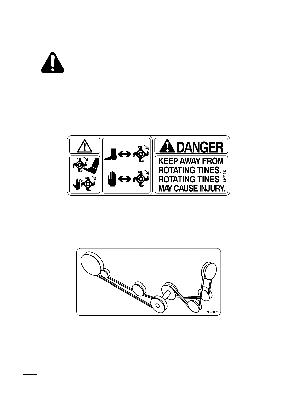
Safety
Safety
and Instruction Decals
Safety decals and instructions are easily visible to the operator and are located near
any area of potential danger. Replace any decal that is damaged or lost.
ON TINE SHIELD
LEFT and RIGHT SIDE
(Part No. 92–71
12)
ON PULLEY BOX
(Part No. 98–8082)
2
Page 5

Installation
Loose
Parts
Note: A rear–mount Attach–A–Matic, which must be purchased separately, is required for this tiller. Use
the chart below to identify other parts used for assembly.
DESCRIPTION QTY. USE
T
iller housing
T
iller lift frame
Panel guard
Cotter pin 1/8” x 1” (25 mm)
Pulley
Square key
Set screw
Belt guard
T
iller belt (short belt)
Idler pulley
Bolt, 3/8–16 x 2” (51 mm)
Nut, 3/8”
T
iller pulley box
PT
O drive belt (long belt)
1
1
1
3
1
1
2
1
1
1
1
1
1
1
Assemble the tiller
Assemble tiller pulley
Installing the belt guard
Install pulley box
Clevis pin 3/8” x 1” (25 mm)
Hairpin cotter
Cable guide
Jack shaft assembly
Lift cable
Trunnion
Clevis pin 5/16” x 1” (25 mm)
Locknut
Hairpin cotter
Washer
Operator manual
2
2
1
1
1
1
1
1
2
1
1
Prepare tractor attachment lift
Install the cable guide
Connect drive belts
Install tiller to tractor
Read before operating
3
Page 6
Installation
Assembling
the T
iller
1. Support the tiller housing so it sets in an upright
position. Remove the 3/8 x 5–1/2” (140 mm)
bolt, 3/8 x 4–1/2” (114 mm) bolt, and (2) 3/8”
locknuts; discard the 1/2” nuts (used as spacers
for shipping).
2. Attach the tiller lift frame to the tiller housing
with the previously removed 3/8 x 4–1/2” (114
mm) bolt, 3/8–16 x 5–1/2” bolt (140 mm), and
(2) 3/8” locknuts (Fig. 1). Torque the nuts to
30–32 ft–lbs.
4
3
1
2
m–1282
Figure 2
1. Panel
2.
guard
Cotter pin (3)
3. Slot
4. Install the pulley by inserting the square key into
the input shaft groove. Slip the pulley onto the
shaft (hub toward the gear case) and align it with
the flat idler pulley. Secure it with two
square–head set screws (Fig. 3).
1
3
5
2
m–3506
Figure 1
1. Tiller
2. T
3.
housing
iller lift frame
Bolt 3/8–16 x 5–1/2” (140
mm)
Locknut 3/8”
4.
5.
Bolt 3/8–16 x 4–1/2” (1
mm)
14
3. Hook the panel guard into the slots on the end of
the tiller housing (Fig. 2). Insert (3) cotter pins
and bend the ends of the pins to secure the panel
guard.
3
2
4
1
m–4423
Figure 3
1. Pulley
2. Key
3. Set screw
4.
Input shaft
5. Remove the nut from the gearcase bolt located
just above the input shaft (Fig. 4). The belt
guard mounts to this bolt.
6. Install the tiller belt (short belt) over the input
pulley.
7. Assemble the belt guard to the gearcase bolt
(step 5) and replace the nut loosely.
4
Page 7
Installation
8. Install the ilder pulley on the 3/8–16 x 2” (51
mm) bolt so that the extended hub of the pulley
is toward the tiller lift frame. Route the belt
under the idler pulley, and insert the bolt through
the upper belt guard hole and upper hole in the
tiller lift frame
(Fig. 4). Tighten the nut securely.
3
2
4
4
1
6
8
5
7
m–4422
Figure 4
1. Belt
2.
Gearcase bolt
3.
Input pulley
4.
Locknut, 3/8”
cover
5.
Bolt, 3/8–16 x 2” (51 mm)
6.
Upper hole
7. T
iller Belt (short belt)
8.
Idler pulley
9. Torque the nut on the gearcase (upper end of belt
guard) to 30–32 ft–lbs.
Installing the Front Pulley Box to the
Tractor
1. Attach the pulley box that came with the tiller to
the front Attach–A–Matic.
IMPORTANT: The pulley box for the tiller
and cutter deck are different. Make certain
to always use the tiller pulley box with the
tiller.
2. Make sure the latches on the tractor’s front
Attach–A–Matic are open (Fig. 5). Then slide
the pulley box into the Attach–A–Matic
latches and seat it. Close the latches.
3
1
7
6
1. Attach–A–Matic
2.
Pulley box
3.
Idler pulley
4.
Belt tension release arm
5.
Belt tension adjustment
knob
22
latches
Figure 5
6.
Belt tension indicators
(one on each side)
7. Attach–A–Matic
button (one on each side)
4
m–3642
release
5
Tractor
Set-Up
Installing the Rear Attach–A–Matic to
the Tractor
Follow the installation instructions that come with the
rear Attach–A–Matic
mount.
Remove the drawbar hitch
1. Remove the snap ring from the pin and slide
from the drawbar and spacers. Remove the hitch
from the tractor (Fig. 6).
Note: Save all hardware for use when
re-installing the hitch.
5
Page 8
Installation
1. Snap
2. Pin
ring
Figure 6
4
2
3. Drawbar
4.
Spacer (2)
2314
1
2
3
1
m–3433
Figure 7
1. Clevis
pin 3/8” x 1” (25
mm)
Hairpin cotter
2.
Preparing the Tractor’s Attachment Lift
If you have been using a mower, secure the tractor’s
attachment lift arms in the raised position.
1. Start the tractor.
2. Raise the attachment lift.
3. Set the parking brake and turn the ignition key to
“STOP” to stop the engine. Remove the ignition
key.
4. Install a 3/8” x 1” (25 mm) clevis pin into each
side of the lift assembly in the positions shown
in Figure 7. Secure them with (2) hairpin
cotters.
These pins must be installed when operating with a
blade, snowthrower, or tiller attachment.
Note: The pins are removed to attach a
mower.
6
Page 9

Remove the Rear Transaxle Cover
Remove the transaxle cover from the back of the
tractor (Fig. 8).
1. Remove the two bolts and locknuts securing the
transaxle cover to the tractor frame.
Note: Save all parts and hardware for use
when reinstalling the transaxle cover.
Installation
POTENTIAL HAZARD
• Rotating shaft or cooling fan can cause
injury.
WHAT CAN HAPPEN
• Fingers, hands, feet, hair, etc. can get
caught by shaft or fan.
• Loose clothing can get caught by shaft.
1
m–3436
Figure 8
1. Rear
transaxle cover
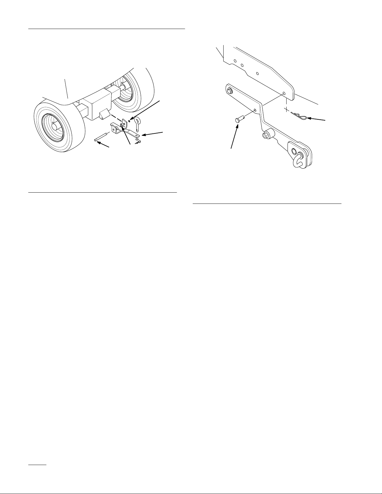
Installing the Cable Guide
The cable guide can be installed from the underside
of the tractor. For more visibilty, the drive shaft
maintenance cover can be removed to aid in
installation.
1. Disengage the power take off (PTO), set the
parking brake and turn the ignition key to
“STOP” to stop the engine. Remove the ignition
key.
HOW TO AV
OID THE HAZARD
• Do not operate the tractor without the drive
shaft cover in place.
• Keep hands and arms clear of rotating
shaft or fan.
2. Remove the two bolts in the plastic fan baffle
(Fig. 9) and remove the baffle.
3. Remove the clip nut from the left side of the
plastic fan baffle and install over the hole in the
bent tab of the cable guide (Fig. 9).
4. Remove the nut from the pivot bolt on the left
hand attachment lift arm (Fig. 9). Leave the bolt
in place.
5. Install the rear hole of the cable guide to the left
hand lift arm pivot bolt and replace the nut
loosely (Fig. 9).
6. Reinstall the plastic fan baffle with one of the
previously removed bolts in the right hand side
only (Fig. 9). Leave the bolt loose.
7. Align the front of the cable guide with the hole
in the left hand side of the plastic fan baffle and
reinstall the other bolt previously removed.
Tighten all bolts and nuts securely.
7
Page 10

Installation
8. Replace the drive shaft maintenance cover (if
removed).
1
9
8
7
6
1. Cable
2.
3.
4. Left
5. Plastic
guide
Clip nut
Fan baf
fle bolt
hand lift arm pivot bolt
nut
fan baf
Figure 9
fle
4
5
6.
Right hand attachment lift
arm
7.
Rear of tractor
8.
Pivot bolt
9.
Lift cable
2
3
1
7
3
6
5
8
2
4
9
m–3491
Figure 10
1. Tiller
2. Jack
3.
4. T
5.
shaft assembly
Lift cable
iller belt (short belt)
Idler pulley
6. T
iller hitch bar
7.
Smaller jack shaft bar
8.
Jack shaft/PT
pulley
9.
Larger jack shaft bar
O drive belt
4. Open the latches on the rear Attach–A–Matic.
Place the smaller bar of the jack shaft assembly
into the slots on the front of the rear
Attach–A–Matic (Fig. 11).
2
3
1
Installing
the T
iller to the
Tractor
1. Position the tiller on a level surface with enough
space behind it to accommodate the tractor.
2. Start the tractor and back it into position. Lower
the attachment lift and turn the ignition key to
“STOP” to stop the engine. Remove the ignition
key.
3. Place the jack shaft assembly between the tractor
wheels and oriented with the tiller as shown
(Fig. 10).
8
1. Smaller
2.
jack shaft bar
Rear Attach–A–Matic
Figure 1
m–3505
1
3. Rear
Page 11

5. Open the latches on the mid Attach–A–Matic.
Install the larger bar at the other end of the jack
shaft assembly to the mid Attach–A–Matic.
Then turn the lever of the Attach–A–Matic
counterclockwise to lock the jack shaft assembly
to the tractor (Fig. 12).
Note: The rear Attach–A–Matic may need
to be loosened and realigned with the
mid Attach–A–Matic
jack shaft assembly
Attach–A–Matic bolts
to accept the
. Tighten the rear
securely.
1. Smaller
2. T
iller hitch bar
4
2
jack shaft bar
Figure 13
3.
4. Rear
Installation
3
1
Rear Attach–A–Matic
3
1
2
4
m–3502
Figure 12
1. Attach–A–Matic
2. Attach–A–Matic
button
lever
3. Lock
4.
Larger jack shaft bar
6. Place the tiller hitch bar into the slots in the rear
of the rear Attach–A–Matic. Press on the
latches at the rear until they lock both the tiller
and the jack shaft assembly in place (Fig. 13).
7. Install the tiller belt (short belt) between the
tiller and jack shaft assembly (Fig. 10). Route
the belt under the ilder pulleys and over the jack
shaft pulley.
8. Attach the clevis end of the lift cable to the rear
hole in the tractor’s attachment lift arm located
just in front of the previously installed cable
guide (Fig. 14). Insert a clevis pin and hairpin
cotter.
Note: Attachment lift arm may be different
than shown in Fig. 14. On some
models there may be only a single hole
in which to mount the clevis.
9
Page 12

Installation
3
4
1
2
5
m–3504
Figure 14
1. Lift
cable
2. Clevis
3.
Attachment lift arm
4.
Clevis pin 5/16” x 1” (25
mm)
5.
Hairpin cotter
9. Route the lift cable under the cable guide and
over the rear axle (Fig. 9).
10. Connect the lift cable to the trunnion by
threading the trunnion onto the lift cable
(Fig. 15).
11. Attach the trunnion to the hole in the tiller lift
cable mount with a washer and hairpin cotter
(Fig. 15).
Note: There should be slack in the cable so
the tiller will drop into the ground.
The amount of cable that is threaded
into the trunnion determines the
maximum depth of tilling and lift
height.
3
4
2
Figure 15
1. Lift
cable
2. Trunnion
3. Locknut
4. Washer
5.
Hairpin cotter
12. Secure the lift cable to the trunnion with a
locknut (Fig. 15).
13. Remove the tractor grille by pulling it out
toward you.
POTENTIAL HAZARD
• Components under the hood will be hot if
the tractor has been running.
WHAT CAN HAPPEN
• Touching hot components can cause burns.
HOW TO AV
OID THE HAZARD
• Allow the tractor to cool before performing
maintenance or touching components
under the hood.
5
1
m–3503
10
14. Route the PTO drive belt around the jack shaft’s
PTO pulley (Fig. 10), then through the center of
the pulley box between the two pulleys.
15. Release the belt tension release arm of the pulley
box housing and swing it out toward you (Fig.
18).
Page 13

Installation
16. Position the end of the PTO belt (long belt) into
the groove of the engine PTO pulley (Fig. 16),
making sure it is also under the pulleys in the
pulley box. The wide, flat surface of the belt
needs to be in contact with the wide, flat surface
of the backside idler pulley (Fig. 17). Additional
belt slack can be obtained (if needed) by turning
the belt tension adjustment knob.
4
3
3.
V–groove idler pulley
4.
Engine PT
5.
Backside idler pulley
m–3561
O pulley
1. Jack
pulley
2. PT
O belt (long belt)
shaft PT
1
2
5
Figure 16
O drive belt
C. If the tension indicators are not in the same
position on both the left and right sides,
release the belt tension, turn the adjustment
knob and repeat steps A and B until the
indicators move to the same position (Fig.
18).
D. Once the indicators are in the same position
on both sides, swing the tension release arm
into the pulley box by moving it into the
position shown in Figure 18.
1
Figure 18
1. Belt
tension indicator (2)
2.
Belt tension adjustment
knob
3.
Seating position for belt
tension release arm
4.
Belt tension released
2
4
m–36433
1
1. V–Groove
Figure
pulley
17
2.
Backside pulley
17. Now adjust the belt tension.
A. Push the belt tension release arm back
toward the pulley box to tension the belt.
B. Check the tension indicators on each side of
the pulley box.
2
18. Replace the front grille of the tractor.
m–3633
11
Page 14

Installation
Removing
the T
iller
Note: Save all hardware, washers and hairpin
cotters for use when installing tiller.
1. Park the tractor on a level surface with enough
space in front of it to disengage from the tiller.
2. Lower the attachment lift, set the parking brake,
and turn the ignition key to “STOP” to stop the
engine. Remove the ignition key.
3. Remove the tractor grille by pulling it out
toward you.
POTENTIAL HAZARD
• Components under the hood will be hot if
the tractor has been running.
WHAT CAN HAPPEN
• Touching hot components can cause burns.
1
4
2
3
5
m–3561
Figure 19
1. Jack
2. PT
shaft PT
pulley
O belt (long belt)
O drive belt
3.
V–groove pulley
4.
Engine PT
5.
Backside idler pulley
O pulley
6. Release the tension on the tiller belt by lifting up
on the idler pulley (Fig. 10). Remove the belt
from the pulleys.
HOW TO AV
OID THE HAZARD
• Allow the tractor to cool before performing
maintenance or touching components
under the hood.
4. Release the belt tension release arm (Fig. 18),
then remove the PTO belt from its position
around the PTO pulley (Fig. 19). Additional belt
slack can be obtained (if needed) by turning the
belt tension adjustment knob.
5. Replace the front grille of the tractor.
7. Disconnect the lift cable by removing the clevis
pin from the clevis and remove the cable from
the attachment lift arm (Fig. 20).
3
4
1
2
5
m–3504
Figure 20
1.
Lift cable
2. Clevis
3.
Attachment lift arm
4.
Clevis pin 5/16” x 1” (25
mm)
5.
Hairpin cotter
12
Page 15

8. Press the release button and open the rear latches
of the rear Attach–A–Matic. Remove the tiller
hitch bar (Fig. 21).
Installation
4
2
Figure 21
1. Smaller
2. T
jack shaft bar
iller hitch bar
3.
Rear Attach–A–Matic
4. Rear
9. Press the release button on the mid
Attach–A–Matic and turn the lever clockwise
to open the latches (Fig. 22). Remove the jack
shaft assembly
.
3
1
m–3501
1
Figure 22
1. Attach–A–Matic
button
2. Attach–A–Matic
10. Replace the rear transaxle cover.
11. Replace the drawbar hitch.
2
m–3502
lever
13
Page 16

Operation
POTENTIAL HAZARD
• Contact with rotating tines may cause
injury.
WHAT CAN HAPPEN
• Rotating tines can cut hands, feet or other
body parts.
1
HOW TO AV
OID THE HAZARD
• Keep away from the rotating tines while
operating the tiller.
• Keep your hands, feet, and any other part
of your body or clothing away from
rotating parts.
• Before adjusting, cleaning, repairing and
inspecting the tiller, shut off the engine and
wait for all moving parts to stop. Move the
power take off (PTO) to “OFF” and rotate
the ignition key to “OFF.” Remove the
ignition key.
Attachment
The attachment power lift (Fig. 23) is used to raise
and lower attachments.
Power Lift
Figure 23
1. Attachment
power lift
Raising Attachments
1. Start the tractor.
2. Pull the lift lever UP to raise the attachment
(Fig. 24). This will lift and hold the attachment
in the raised position.
POTENTIAL HAZARD
• When the engine is off, attachments in the
raised position can gradually lower.
WHAT CAN HAPPEN
• Someone nearby may be pinned or injured
by the attachment as it lowers.
m–3258
14
HOW TO AV
OID THE HAZARD
• Always lower the attachment lift each time
you shut off the tractor.
Page 17

Operation
Lowering
1. Start the tractor.
2. Push the lift lever DOWN to lower the
attachment (Fig. 24).
1. Lift
lever–Up
Attachments
1
Figure 24
2.
Lift lever–Down
2
m–3315
Tips
Clean area of trash, branches and rocks before tilling
to prevent equipment damage.
Always begin tilling with the slowest ground speed
possible. Increase speed if conditions permit.
Always use full throttle (maximum engine speed)
when tilling.
Always engage the power take off (PTO) with tiller in
the raised position.
Till in long, straight passes. Do not make turns while
the tiller is in the ground, as equipment damage may
result.
A small center area will not be tilled due to the gear
case. Overlapping with a second pass will eliminate
this condition.
Avoid excessive tilling of the soil, as finely tilled soil
will not absorb moisture easily and puddles of water
or run-off may occur.
for T
illing
When tilling hard packed, very dry or virgin soil,
raise the tiller so only the very top of the soil is
penetrated. On succeeding passes the depth may be
lowered. This reduces the tiller’s tendency to push the
tractor. If this happens, disengage the power take off
(PTO) and reduce forward speed.
Use low range (on the high–low range lever) for best
performance and smoothest operation.
POTENTIAL HAZARD
• There may be buried power, gas, and/or
telephone lines in the area needing tilling.
WHAT CAN HAPPEN
• Shock or explosion may occur.
HOW TO AV
OID THE HAZARD
• Have the property or area to be tilled
marked for buried lines.
15
Page 18

Maintenance
Service
Service
Oil–check level
Belt tension–check
Belt–check for wear/cracks
Chipped surfaces–paint
Interval Chart
Operation
POTENTIAL HAZARD
• If you leave the key in the ignition switch, someone could start the engine.
WHAT CAN HAPPEN
• Accidental starting of the engine could seriously injure you or other bystanders.
HOW TO AV
• Remove the key from the ignition switch and pull the wire(s) off the spark plug(s)
before you do any maintenance. Also push the wire(s) aside so it does not
accidentally contact the spark plug(s).
OID THE HAZARD
Each
Use5Hours25Hours
X X X
initial X X
Storage
Service
X X
X
Fall
Service
Notes
16
Page 19

Maintenance
Greasing
and Lubrication
Service Interval/Specification
Check the gear lubrication level in the gear case after
every 25 operating hours or once a year, whichever
occurs first. Gear lubrication changes are not
required.
Gear lube type: SAE 90-140 API service GL-4 or
GL-5.
Refill capacity: 1 qt.
Checking Gear Lube
1. Position the tractor and tiller on a level surface
and lower the attachment lift so that the tiller
tines are on the ground. Set the parking brake
and turn the ignition key to “STOP” to stop the
engine. Remove the ignition key.
2. Clean the area around the lower pipe plug
(Fig. 25).
3. Remove the pipe plug carefully because the oil
level may be above the level of the pipe plug.
1
Figure 25
Left side of tiller shown in operating position
1. Pipe
plug (hidden)
Checking Tiller Drive Belt
Tension
1. Disengage the power take off (PTO), set the
parking brake, lower the attachment lift and turn
the ignition key to “STOP” to stop the engine.
Remove the ignition key.
m–3497
4. If gear lube runs from the case when the plug is
removed, the lube in the case is sufficient. Oil
may be added as necessary
5. Apply pipe sealant to the plug and reinstall.
.
2. As the drive belt wears and the tiller is raised
and lowered, the spring–loaded idler arm moves
(Fig. 26).
3. Lower the tiller and observe the spring–loaded
idler arm movement as you push on the belt. The
idler arm spring must be under tension. If it is
not under tension, replace the drive belt.
Replacing
1. Disengage the power take off (PTO), set the
parking brake, lower the attachment lift and turn
the ignition key to “STOP” to stop the engine.
Remove the ignition key.
2. Remove the rear tiller belt (short belt) from the
jack shaft pulley (Fig. 26).
the T
iller Drive Belt
17
Page 20

Maintenance
1
2
3
Figure 26
1. Spring
2. T
loaded idler arm
iller drive belt (short belt)
3.
Jack shaft pulley
3. Remove the belt guard from the gear box and
ilder mounting (Fig. 27).
m–3491
3
2
4
4
1
6
8
5
7
m–4422
4. Remove the belt and replace with a new one.
5. Reinstall the belt guard (Fig. 27) Refer to
“Assembling the Tiller” under Installation. Be
sure to torque the gear case bolt.
Figure 27
1. Belt
cover
2.
Gearcase bolt
3.
Input pulley
4.
Locknut, 3/8”
Checking
PT
O Drive Belt
5.
Bolt, 3/8–16 x 2” (51 mm)
6.
Upper hole
7. T
iller Belt (short belt)
8.
Idler pulley
Tension
1. Check the tension indicators on each side of the
pulley box. If the tension indicators are not in
the same position on both the left and right
sides, release the belt tension and turn the
adjustment knob. Push the belt tension release
arm back toward the pulley box to tension the
belt (Fig. 28).
2. Repeat step 1 until the indicators move to the
same position.
18
3. Once the indicators are in the same position on
both sides, swing the tension release arm into the
pulley box by moving it into the position shown
in Figure 28.
Page 21

Maintenance
2
1
3
m–3643
Figure 28
1. Belt
tension indicator (2)
2.
Belt tension adjustment
knob
3.
Seating position for belt
tension release arm
4.
Belt tension released
Storage
1. Before long term storage wash the machine with
mild detergent and water to remove dirt and
grime from the entire machine.
2. Check the condition of the drive belt.
3. Check gearcase lubrication level; refer to
Greasing and Lubrication, page 17.
4
4. Check and tighten all bolts, nuts, and screws.
Repair or replace any part that is damaged or
defective.
5. Paint all scratched or bare metal surfaces. Paint
is available from your Authorized Service
Dealer.
6. Store the tiller in a clean, dry garage or storage
area. Cover the tiller to protect it and keep it
clean.
19
Page 22

Page 23

Page 24

 Loading...