


FORM NO. 3318–329 Rev. A
Wheel
Horse
36” Tiller
for
Classic
Model No. 79370 – 6900001 & Up
Garden T
ractors
Operator’s Manual
IMPORTANT: Read this manual carefully. It contains information about your
safety and the safety of others. Also become familiar with the controls and
their proper use before you operate the product.
Introduction
We want you to be completely satisfied with your
new product, so feel free to contact your local
Authorized Service Dealer for help with service,
genuine replacement parts, or other information you
may require.
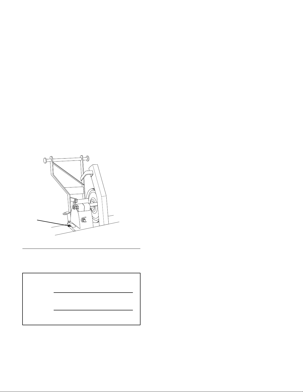
Whenever you contact your Authorized Service
Dealer or the factory, always know the model and
serial numbers of your product. These numbers will
help the Service Dealer or Service Representative
provide exact information about your specific
product. You will find the model and serial number
plate located in a unique place on the product as
shown below
.
The warning system in this manual identifies
potential hazards and has special safety messages that
help you and others avoid personal injury, even death.
DANGER, WARNING and CAUTION are signal
words used to identify the level of hazard. However,
regardless of the hazard, be extremely careful.
DANGER signals an extreme hazard that will cause
serious injury or death if the recommended
precautions are not followed.
WARNING signals a hazard that may cause serious
injury or death if the recommended precautions are
not followed.
CAUTION signals a hazard that may cause minor or
moderate injury if the recommended precautions are
not followed.
Two other words are also used to highlight
information. “Important” calls attention to special
mechanical information and “Note” emphasizes
general information worthy of special attention.
1
2276
1. Model
For your convenience, write the product model and
serial numbers in the space below.
Model No:
Serial No.
and Serial Number Plate
The left and right side of the machine is determined
by sitting on the seat in the normal operator’s
position.
Printed in USA

Contents
Page
Safety and Instruction Decals 2.
Installation 3
Loose Parts 3
Assemble T
Tractor Set-Up 6
Installing Tiller to Tractor 9
Removing the Tiller 12
Operation 14
Operating the Power Take Off (PTO) 14
Attachment Lift Lever 15
. . . . . . . . . . . . . . . . . . . . . . . . . . . . .
. . . . . . . . . . . . . . . . . . . . . . . . .
iller 5
. . . . . . . . . . . . . . . . . . . . .
. . . . . . . . . . . . . . . . . . . . . .
. . . . . . . . . . . . . . . . . . . . . . . . . . . . . .
. . . . . . . . . . . . .
. . . . . . . . . . . . .
. . . . . . . . . . . . . . . . . .
. . . .
. . . . . . . . . . . . . . . .
Page
Attachment Power Lift 15
Adjusting Dial-A-Height 16
Adjusting Lift Chain 16
Tips for Tilling 17
Maintenance 18
Service Interval Chart 18
Greasing and Lubrication 19
Adjusting Drive Belt Tension 19
Storage 20
. . . . . . . . . . . . . . . . . . . . . . . . . . . .
. . . . . . . . . . . . . . . . . . . . . . . . . . . .
. . . . . . . . . . . . . . . . . . . . . .
. . . . . . . . . . . . . . . .
. . . . . . . . . . . . . .
. . . . . . . . . . . . . . . . .
. . . . . . . . . . . . . . . .
. . . . . . . . . . . . . .
. . . . . . . . . .
1
Safety
Safety
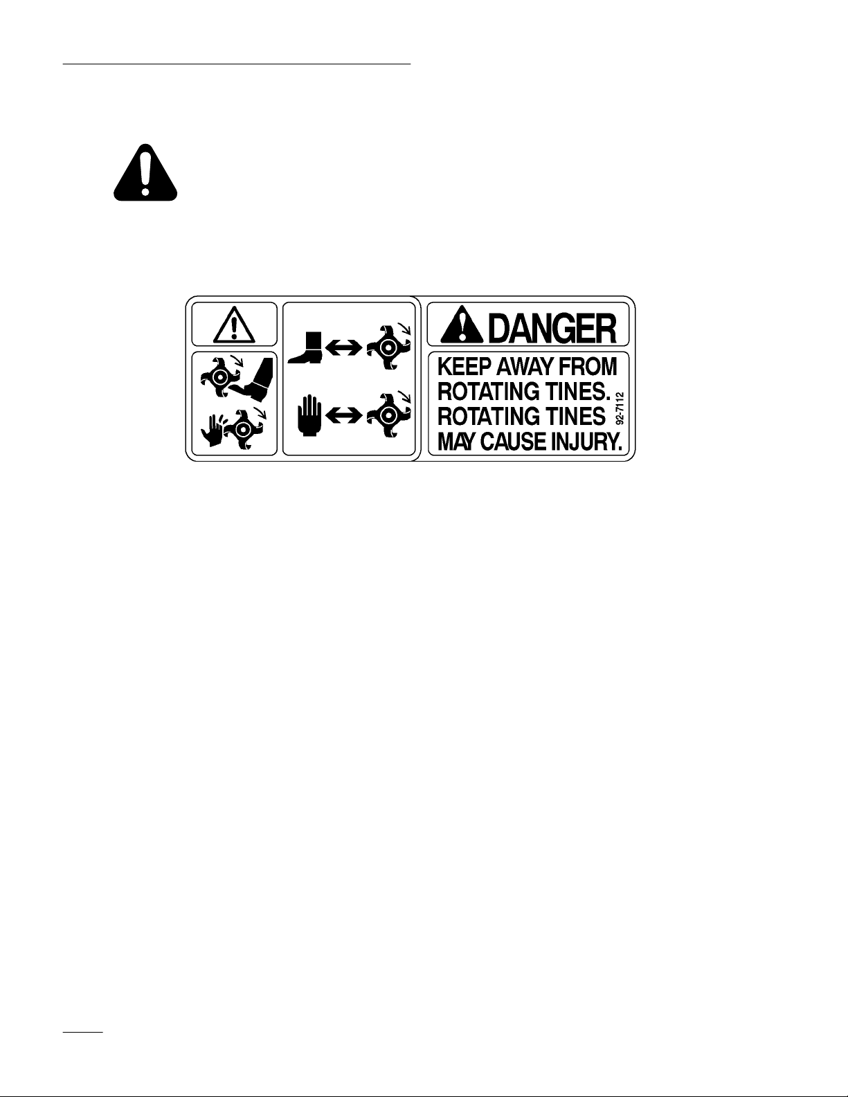
and Instruction Decals
Safety decals and instructions are easily visible to the operator and are located near
any area of potential danger. Replace any decal that is damaged or lost.
ON TINE SHIELD
LEFT and RIGHT SIDE
(Part No. 92–71
12)
2

Installation
Loose
Parts
Note: Use the chart below to identify parts for assembly.
DESCRIPTION QTY. USE
Hitch
Spring bracket
Bolt (installed in case for shipping) 3/8 x 5-1/2”
Nut (installed in case for shipping) 3/8”
Pulley
Key
Set screw 15/16”
Idler pulley
Spacer
Belt guide
Belt guard
Bolt 3/8–16 x 2-1/4”
Lock nut 3/8”
1
1
2
2
1
1
1
1
1
1
1
1
1
Install tiller hitch to tiller gear case.
Install drive pulley to tiller gear case.
Install idler pulley and belt guard.
Rear shield
Cotter pin 1”
Lift chain
Clevis
Clevis pin
Cotter pin 3/4”
Tube-Hydro\Gear
Clamp
Cable
Clevis-Short\Long
Clevis pin
Cotter pin 1”
Trunnion
W
asher 5/8”
1
3
1
1
1
1
2
1
1
2
1
2
1
1
Install rear shield to tiller
Install lift chain to tiller
Install lift cable to tractor
.
.
.
3

Installation
DESCRIPTION USEQTY.
Lift lever
Bushing
Shim washer
E-ring
Latching plate
Latch lever
Carriage bolt 3/8–16 x 1”
W
asher 3/8”
Lock nut 3/8”
Clevis pin
Cotter pin 3/4”
Latch plate assembly
Link bracket-right
Link bracket-left
Angle spacer (if required)
Carriage bolt 3/8–16 x 3-1/2”
Lock nut 3/8”
1
2
4
2
1
2
2
2
2
2
2
1
1
1
1
4
4
Install lift lever to tractor
Assemble mounting plate.
Install mounting plate to tractor
.
.
Spring-large
Eye bolt
Lock nut 3/8”
Mid-mount bracket assembly
Belt
Bolt 3/8–16 x 2-3/4”
Bolt 3/8–16 x 1-3/4”
W
asher 38”
Lock nut 3/8”
Spring-small
Belt guard
Bolt-self tapping 1/4 x 1/2”
1
1
1
1
1
1
1
1
3
1
1
2
Install lift assist spring to tiller
Install idler pulley assembly to tractor
.
.
4
Installation
Assemble Tiller
1. Tip tiller onto back and support in an upright
position. Remove 3/8 x 5-1/2” and 3/8 x 4-1/2”
bolts. (Fig. 1). Discard extra nuts used as spacers
for shipping.
2. Fasten hitch and spring bracket with bolts and
nuts as shown in (Fig. 1). Tighten bolts securely.
3. Install pulley with hub 1/4” in from the end of
drive shaft (Fig. 1). Secure with square key and
(2) 5/16” square head set screws.
IMPORTANT: Key must be located under a
set scr
ew to be retained.
4. Assemble idler and belt guide into lower hole of
belt guard and install onto hitch through upper
hole with 3/8 x 2-1/4” bolt and 3/8” lock nut
(Fig. 1).
10
1
8
11
9
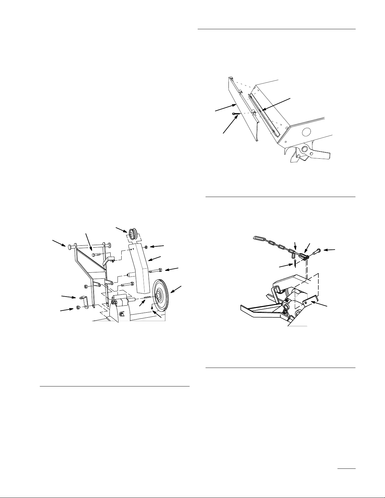
5. Rotate tiller down and hook rear shield into slots
at rear of tine shield. Secure with (3) 1” cotter
pins (Fig. 2).
3
1
2
1282
Figure 2
1. Rear
2.
shield
Cotter pin 1”
3. Slot
6. Attach lift chain, short link end, one link short,
to lift bracket with clevis, clevis pin and secure
with 3/4” cotter pin (Fig. 3).
1
2
3
2
4
1. Hitch
2. Spring
3.
4.
5. Pulley
6. Key
bracket
Bolt (in tiller case)
Nut (on tiller bolt)
Figure 1
6
7.
Set screw 5/16”
8. Idler
9.
Belt cover
10.
Bolt 3/8–16 x 2-1/4”
11.
Lock nut 3/8”
3
5
5
4
2292
7
2294
Figure 3
1. Short
2. Clevis
3.
link
Clevis pin
4. Bracket
5.
Cotter pin 3/4”
5
Installation
Tractor
Set-Up
1. Remove and save carriage bolts at fender mount
under the seat and attaching footrests. (Fig. 4).
2. Unplug seat wiring harness connector and
remove wire harness from wire clip.
Note: If tractor has a 25 amp fuse clipped
inside console, remove the fuse.
3. Remove the fender\seat pan from the tractor.
Note: Save all hardware for use when
re-installing fenders.
2
2
2
1
2
4. Remove bolts and lock washers securing fuel
tank bracket to the top of transmission.
5. Select proper cable tube (straight for gear drive,
bent for hydrostatic) and install on the top of fuel
tank bracket. Secure to fuel tank bracket with
clamp and previously removed lock washers and
bolts.
2
1
1. Cable
2.
tube-gear drive
Cable tube-hydrostatic
Figure 5
3
4
2293
3. Clamp
4. Bracket
1. Fender\seat
pan
Figure 4
2.
Carriage bolt
1229a
6

Installation
6. Slide a shim washer and bushing onto ends of
lift lever rod (Fig. 6).
IMPORTANT: Check that bushings slide
easily onto rod ends and into frame. Remove
paint if necessary.
7. Position lift lever into frame and slide bushings
and shim washers outward into frame holes.
Secure in position with E-rings (Fig. 6).
IMPORTANT: Lift lever must not have
excessive end play (more than .015 inch). Use
extra shim washers (.015 and .020 thick) to
reduce end play.
1
2
5
3
8. Slide ball end of attachment lift cable through
cable tube from the rear.
9. Select correct clevis as follows:
2” long clevis: for 8-speed gear drive and
hydrostatic models with oil filter on right side.
3-1/8” long clevis: for hydrostatic models with
oil filter facing rear.
10. Lower attachment lift and place cable, ball end,
into slot in clevis (Fig. 7). Attach clevis to hole
in attachment lift and secure with clevis pin and
and 1” cotter pin. (Fig. 7).
3
2
Figure 6
1. Bushing
2. Shim
W
required)
asher (as
3.
Lift lever
4.
Frame hole
5. E-ring
Note: If tractor has a 25 amp fuse clipped
inside console, install the fuse.
5
4
2291
1. Lift
cable knob
2.
Clevis (select proper size)
3.
Attachment lift
4
Figure 7
4.
5.
1
2315
Clevis pin
Cotter pin 1”
7

Installation
11. Thread trunnion 1” into end of lift cable threaded
end and insert into lower hole of lift lever.
Secure with 5/8” washer and hairpin cotter
(Fig. 8).
4
Figure 8
3
4. W
asher 5/8”
5.
Hairpin cotter
5
2309
1. Trunnion
2. Lift
cable threaded end
3.
Lower hole in lift lever
1
2
12. Install fenders and seat with previously removed
hardware.
15. Center hitch on axle housing and install with (4)
3/8 x 3-3/4” carriage bolts, left side angle plate
(with hole rearward), right side strap and 3/8”
lock nut as shown (Fig. 10).
Note: On hydrostatic models with oil filter
facing rear locate hitch 3-1/4” (8.3 cm)
from right side of center housing.
Note: To tighten hitch mounting, install
angle spacers, positioned along top and
rear of axle, on 8-speed gear drive and
hydrostatic models with oil filter on
right side.
6
5
4
7
13. Plug seat wiring harness connector and insert
wire harness into wire clip.
14. Install latch levers to mounting plate with
3/8 x 1” carriage bolts, 3/8” washers and 3/8”
lock nuts (Fig. 9).
Note: Tighten nuts so latch levers move, but
hold in position for ease of tiller
mounting to tractor.
3
5
1
Figure 9
1. Mounting
2.
Carriage bolt 3/8 x 1”
3. W
plate
asher 3/8”
4.
Latch lever
5.
Lock tut 3/8”
4
2308
3
7
1
2
2295
Figure 10
1. Mounting
2.
Carriage bolt 3/8 x 3-3/4”
3.
Angle plate-left side
4.
Strap-right side
plate
5.
Lock nut 3/8”
6.
3-1/4” (8.3 cm) location
7.
Angle spacer-if required
2
8

Installation
16. Check mounting location of idler arm in hole of
idler bracket (Fig. 11). Correct location is as
follows:
Front hole for 400 & 500 Series Twin cylinder
tractors and all Single cylinder tractors.
Rear hole for C & GT Series Twin cylinder
tractors.
17. If necessary, remove 3/8” lock nut (Fig. 11) and
change idler arm hole location. Secure with same
lock nut.
5
3
2
1. Front
2.
Rear hole
3.
Lock nut 3/8”
hole
Figure 1
1
1
4.
Idler arm assembly
5.
Idler bracket
4
2310
Installing Tiller to T
ractor
1. Remove snap ring from pin and slide from
drawbar and spacers. Remove hitch from tractor
(Fig. ).
Note: Save all hardware for use when
re-installing hitch.
1
3
2
2314
Figure 12
1. Snap
2. Pin
ring
3. Drawbar
4. Spacer
1. Park the machine on a level surface, disengage
the power take off (PTO), set the parking brake,
and turn the ignition key to “OFF” to stop the
engine. Remove the key.
2. Position tiller behind and under rear tractor hitch
with idler pulley bracket above right latch lever.
Lift latch levers and install frame mounting rod.
Center tiller between hitch latches (Fig. 13).
3. Secure latch levers closed with clevis pins and
hairpin cotters (Fig. 13).
4
1
2296
1. Latch
2.
Mounting rod
3
Figure 13
lever
3.
Clevis pin
4.
Hairpin cotter
2
9

Installation
4. Set Dial-a-Height to the Mounting Position, and
lower attachment lift all the way; refer to Setting
Height-of-Cut.
5. Remove trunnion and slide long link of lift chain
under attachment lift arm and hook into lower
notch (Fig. 14). Install trunnion into bottom hole
of lift lever.
6. Raise attachment lift lever to the transport
position and place a block under tiller gear case.
7. Hook lift assist spring through left hitch angle
mounting plate and eye bolt. Secure eye bolt
through bracket with 3/8” lock nut (Fig. 14).
Adjust lock nut so there is light spring tension in
the fully raised position.
1
2
2
4
5
1
3
6
2311
Figure 15
1. Mid-mount
2.
idler bracket
3. Spring
hitch
4.
Bolt 3/8 x 1-3/4”
5.
Lock nut 3/8”
6.
Idler arm assembly
11. Remove hairpin cotter and trunion from PTO
engagement plate (Fig. 16).
12. Unlatch and remove clevis pin that secures yoke
assembly to clutch shaft and pivot forward to
remove from engagement plate (Fig. 16).
3
4
5
6
7
2297
Figure 14
1. Long
2. Notch
3. Trunnion
4.
link
Lift assist spring
5.
Eye bolt
6. Bracket
7.
Lock nut 3/8”
8. Open mid-mount hitch and insert rod of idler
bracket(Fig. 15).
9. Slide spring onto 3/8 x 1-3/4” bolt and thread on
first 3/8’ lock nut (Fig. ). Place bolt through hole
in frame, just in front of mid-mount hitch, and
secure with a second 3/8” lock nut (Fig. 15).
10. Hook spring into hole in idler arm assembly.
4
1. Hairpin
2. Trunnion
3.
cotter
Engagement plate
5
2
3
1
6
1
2300
Figure 16
4.
Clevis pin
5. Yoke
6.
Clutch shaft
10

Installation
13. Loop belt between clutch yoke and engagement
plate and place on inner groove of PTO, power
take off clutch (Fig. 16).
14. Assemble yoke and engagement plate and attach
clevis pin, trunnion and hairpin cotter to secure
(Fig. 16).
15. Route belt around and mid-mount idler pulleys,
below frame and behind right rear tire (Fig. 17).
16. Pull on idler arm spring to relieve tension and
route belt around tiller drive pulley, under tiller
idler and inside belt guide (Fig. 17).
17. Check that belt is properly routed around all
pulleys and belt guide (Fig. 17).
IMPORTANT: Belt must be properly routed
behind belt guide to prevent jumping off and
premature failure.
3 1
18. Install belt guard to mid-mount bracket with (2)
1/4 x 1/2” self tapping bolts (Fig. 18).
1
2
1. Belt
guard
2.
Mid-mount bracket
3
Figure 18
3.
Bolt 1/4 x 1/2”
2312
1. Inner
2.
groove of (PT
power take of
Mid-mount idler pulleys
f, clutch
Figure 17
O)
4
2313
2
3. T
iller pulley
4. T
iller idler
11

Installation
Removing
the T
iller
Note: Save all hardware, washers and hairpin
cotters for re-use when installing tiller.
1. Park the machine on a level surface, disengage
the power take off (PTO), set the parking brake,
and turn the ignition key to “OFF” to stop the
engine. Remove the key.
2. Turn the Dial-a-Height knob counterclockwise,
all the way and lower the attachment lift lever to
the mounting position; refer to Lowering
Attachment.
3. Remove the belt guard (Fig. 18).
4. Pull on idler arm spring to relieve belt tension
and remove tiller drive belt from tiller pulley and
slide belt out of groove (Fig. 19).
5. Remove hairpin cotter and trunion from power
take off PTO engagement plate (Fig. 19).
2
5
4
3
1
7
6
1
8
2300
Figure 19
1. Hairpin
2. Trunnion
3.
4.
cotter
Engagement plate
Clevis pin
5. Yoke
6.
Clutch shaft
7.
Belt groove
8.
Idler arm
9. Open mid-mount hitch and remove idler bracket
assembly (Fig. 20). Unhook spring from idler
arm (Fig. 20).
6. Unlatch and remove clevis pin that secures yoke
assembly to clutch shaft and pivot forward to
remove from engagement plate (Fig. 19).
7. Remove belt from between clutch yoke and
engagement plate (Fig. 19).
8. Assemble yoke and engagement plate and attach
clevis pin, trunnion and hairpin cotter to secure
(Fig. 19).
10. Remove second lock nut from spring mounting
bolt and remove (Fig. 20).
1
4
2
1. Mid-mount
2.
Idler bracket assembly
hitch
Figure 20
3. Spring
4.
3
Lock nut
2311
12

Installation
11. Raise attachment lift to the transport position
and place a block under tiller gear case.
12. Loosen lock nut on eye bolt and unhook lift
assist spring from tractor (Fig. 21).
13. Turn the Dial-a-Height knob counterclockwise,
all the way, remove block and lower the
attachment lift lever to the mounting position;
refer to Lowering Attachment.
14. Remove hairpin cotter and trunnion from lift arm
and unhook long link of lift chain from lift arm
(Fig. 21). Install trunnion and hairpin cotter
(Fig. 21).
5
3
4
15. Remove hairpin cotters and clevis pins from
latch levers (Fig. 22). Open latch levers and
remove mounting rod.
2
1
3
2296
4
Figure 22
1. Hairpin
2.
cotter
Clevis pin
3.
Latch lever
4.
Mounting rod
Note: Save all hardware, washers and hairpin
cotters for reuse when installing tiller.
1. Lock
2.
3.
nut
Lift assist spring
Hairpin cotter
2
Figure 21
4. Trunnion
5.
1
Long link
2297
13

Operation
POTENTIAL HAZARD
• Rotating tines can cut hands, feet or other
body parts.
WHAT CAN HAPPEN
• Contact with rotating tines may cause
injury.
HOW TO AV
• Keep away from the rotating tines while
operating the tiller.
• Keep your hands, feet, and any other part
of your body or clothing away from
rotating parts.
• Before adjusting, cleaning, repairing and
inspecting the tiller, shut off the engine and
wait for all moving parts to stop. Move the
power take off (PTO) to “OFF” and rotate
the ignition key to “OFF.” Remove the key.
OID THE HAZARD
Operating
Power T
The power take off (PT
power to the clutch.
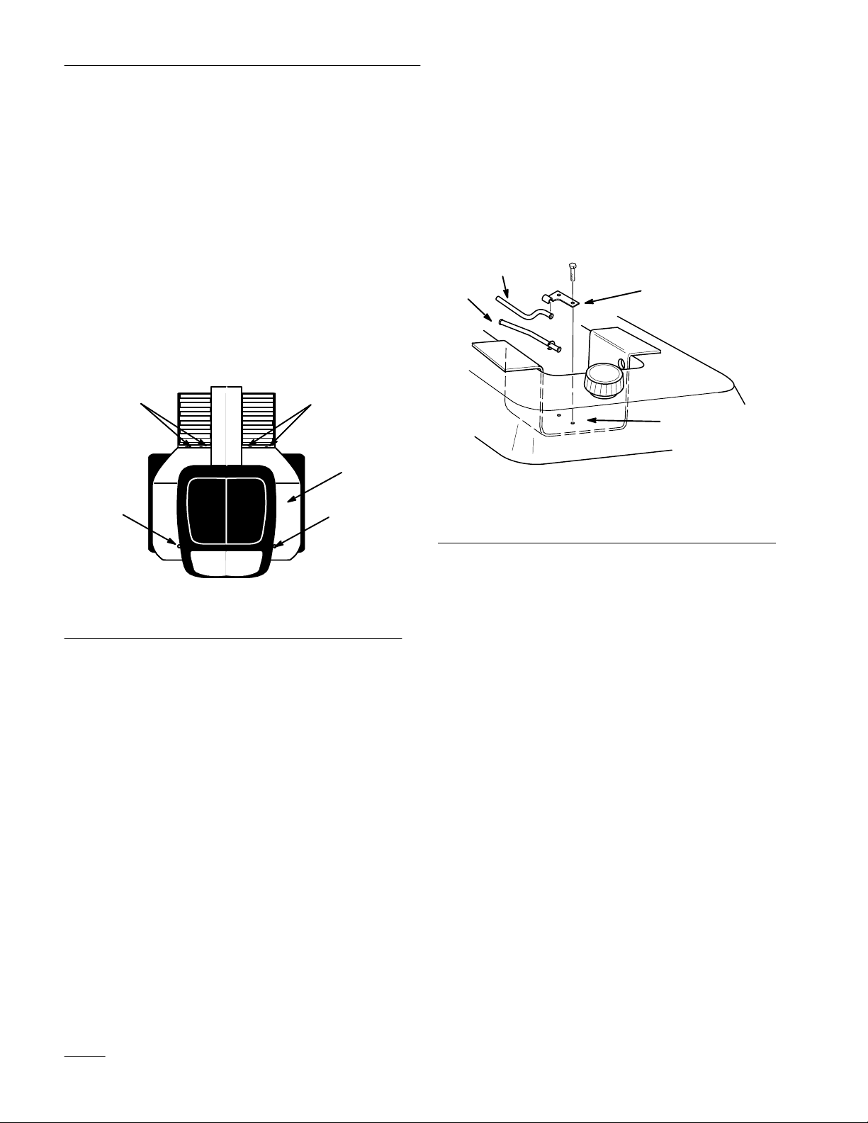
Engaging the Power Take Off (PTO)
1. Depress the brake and/or clutch pedal(s) to stop
the machine.
2. Move the power take off (PTO) to “ON”
(Fig. 23).
the
ake Off (PT
O) engages and disengages
O)
2
1
2318
Figure 23
1. Off-Disengaged 2. On-Engaged
Disengaging the Power Take Off (PTO)
1. Depress the brake and/or clutch pedal(s) to stop
the machine.
2. Move the power take off (PTO) to “OFF”
(Fig.23).
14

Operation
Attachment
Lift Lever
The attachment lift lever (Fig. 24) is used to raise and
lower various attachments.
Raising Attachments
1. Depress the clutch and/or brake pedal(s) to stop
the machine.
2. Pull attachment lift lever rearward until latch
locks. In this position the lift will hold the
attachment in the up, or raised position.
Lowering Attachments
1. Depress the clutch and/or brake pedal(s) to stop
the machine.
2. Pull attachment lift lever rearward, to release lift
pressure, and push the button on top to release
the latch. Move lift lever forward to lower
attachment.
Attachment
Power Lift
The attachment power lift (optional on some models)
(Fig. 25) is used to raise and lower attachments.
Raising Attachments
1. Start the engine.
2. Move the lift lever in the “UP” direction to raise
the attachment lift (Fig. 25). This will lift and
hold the attachment in the up, or raised position.
Lowering Attachments
1. Start the engine.
2. Move the lift lever in the “DOWN” direction to
lower the attachment lift (Fig. 25). This will
lower the attachment lift.
2
3
5
4
6
1. Lift
lever
2. Button
3. Dial-A-Height
Figure 24
4. Indicator
5. High
6.
2
1
Mounting position
2321
1. Lift
1
lever UP
Figure 25
2.
2317
Lift lever DOWN
15

Operation
Adjusting
Dial-A-Height
The Dial-A-Height control (Figs. 24) is used to limit
the downward travel of the attachment, on gear drive
tractors only. The Dial-A-Height knob is rotated to
change the location of this stop, up or down.
1. Raise the attachment lift lever: Refer to Raising
Attachments. In the raised position the
Dial-A-Height knob (Fig. 24) can be rotated to
change the stop location. Turn clockwise to raise
and counterclockwise to lower the height of the
attachment.
2. The Dial-A-Height indicator (Fig. 24) will show
the change, high to low, in attachment lift height
as adjustment is made.
Adjusting
Lift Chain
1. For maximum tilling depth and transport lift
height locate link of lift chain in the lowest
notch of lift lever (Fig. 26). This position will
have the greatest lift effort.
2. For minimum tilling depth and reduced lift
height, locate the link of lift chain in the upper
clevis notch of lift lever (Fig. 26). This position
will have lowest lift effort.
3. For variations of less than the three notches in
the lift lever, disconnect the lift cable from the
lift arm and rotate the trunnion (Fig. 26) Turning
clockwise increases lift height and reduces tilling
depth and counter clockwise reduces lift height
and increases tilling depth.
2
3
1
POTENTIAL
HAZARD
• Rotating tines can cut hands, feet or other
body parts.
WHAT CAN HAPPEN
• Contact with rotating tines may cause
injury.
HOW TO AV
OID THE HAZARD
• Keep away from the rotating tines while
operating the tiller.
• Keep your hands, feet, and any other part
of your body or clothing away from
rotating parts.
• Before adjusting, cleaning, repairing and
inspecting the tiller, shut off the engine and
wait for all moving parts to stop. Move the
power take off (PTO) to “OFF” and rotate
the ignition key to “OFF.” Remove the key.
Changing the lift chain link location at the lift arm
notch, affects maximum tilling depth, transport lift
height and lift effort. The location can be changed at
the lever (Fig. 26).
1. Lowest
2.
Highest notch
notch
4
Figure 26
3.
Lift cable
4. Trunnion
2309
16

Operation
Tips
Clean area of trash, branches and rocks before tilling
to prevent equipment damage.
Always begin tilling with the slowest ground speed
possible. Increase speed if conditions permit.
Always use full throttle (maximum engine speed)
when tilling.
Always engage the power take off (PTO) with tiller in
the raised position.
Till in long straight passes. Do not make turns while
tiller is in the ground, as equipment damage may
result.
A small center area will not be tilled due to the gear
case. Overlapping with a second pass will eliminate
this condition.
Avoid excessive tilling of the soil, as finely tilled soil
will not absorb moisture easily and puddles of water
or run-off may occur.
for T
illing
When tilling hard packed, very dry or virgin soil,
raise tiller so only the very top of the soil is
penetrated. On succeeding passes the depth may be
lowered. This reduces the tendency of the tiller to
push the tractor. If this happens, disengage power
take off (PTO) and reduce forward speed.
17

Maintenance
Service
Service
Oil–check level
Belt–check for wear/cracks
Chipped Surfaces–paint
Interval Chart
Operation
POTENTIAL HAZARD
• If you leave the key in the ignition switch, someone could start the engine.
WHAT CAN HAPPEN
• Accidental starting of the engine could seriously injure you or other bystanders.
HOW TO AV
• Remove the key from the ignition switch and pull the wire off the spark plug before
you do any maintenance. Also push the wire aside so it does not accidentally contact
the spark plug.
OID THE HAZARD
Each
Use5Hours25Hours
X X X
Storage
Service
X X
X
Fall
Service
Notes
18

Maintenance
Greasing
and Lubrication
Service Interval/Specification
Check the gear lube level in the gear case after every
25 operating hours or once a year, whichever occurs
first. Gear lube changes are not required.
Gear lube type: SAE 90-140 API service GL-4 or
GL-5.
Refill capacity: 1 qt.
Checking Gear Lube
1. Position the tractor and tiller on a level surface
and lower the attachment lift so that the tiller
tines are on the ground. Set the parking brake
and turn the ignition key to “STOP” to stop the
engine. Remove the key.
2. Clean the area around the lower pipe plug
(Fig. 27).
Adjusting
Drive Belt T
ension
The drive belt is spring loaded and needs only
periodic adjustment, to maintain proper spring
tension.
Checking Drive Belt Tension
1. Disengage the power take off (PTO), set the
parking brake, and turn the ignition key to
“OFF” to stop the engine. Remove the key.
2. As the drive belt wears, and the tiller is raised
and lowered, the spring loaded idler arm moves
(Fig. 28).
3. Lower the tiller and observe the spring loaded
idler arm movement as you push on the belt. The
idler arm spring must be under tension. If it is
not under tension, replace the drive belt.
3. Remove the pipe plug carefully because the oil
level may be above the level of the pipe plug.
4. If gear lube runs from the case when the plug is
removed, the lube in the case is sufficient. Oil
may be added as necessary
Figure 27
Left side of tiller shown in operating position
1. Pipe
plug (hidden)
.
1
m–3497
1. Spring
loaded idler arm
Figure 28
2. Spring
2
1
2319
19

Maintenance
Storage
1. Before long term storage wash the machine with
mild detergent and water to remove dirt and
grime from the entire machine.
2. Check the condition of the drive belt.
3. Check gearcase lubrication level; refer to
Greasing and Lubrication, page 19.
4. Check and tighten all bolts, nuts, and screws.
Repair or replace any part that is damaged or
defective.
5. Paint all scratched or bare metal surfaces. Paint
is available from your Authorized Service
Dealer.
6. Store the machine in a clean, dry garage or
storage area. Cover the machine to protect it and
keep it clean.
20


 Loading...