

Page 1

FORM NO. 3322–158 Rev A
Wheel Horse
44” Snowthrower
for
5xi Lawn and Garden Tractors
Model No. 79366 – 9900001 & Up
Operator’s Manual
IMPORTANT: Read this manual, and your tractor manual, carefully. They
contain information about your safety and the safety of others. Also
become familiar with the controls and their proper use before you operate
the product.
Page 2
Introduction
We want you to be completely satisfied with your
new product, so feel free to contact your local
Authorized Service Dealer for help with service,
genuine replacement parts, or other information you
may require.
Whenever you contact your Authorized Service
Dealer or the factory, always know the model and
serial numbers of your product. These numbers will
help the Service Dealer or Service Representative
provide exact information about your specific
product. You will find the model and serial number
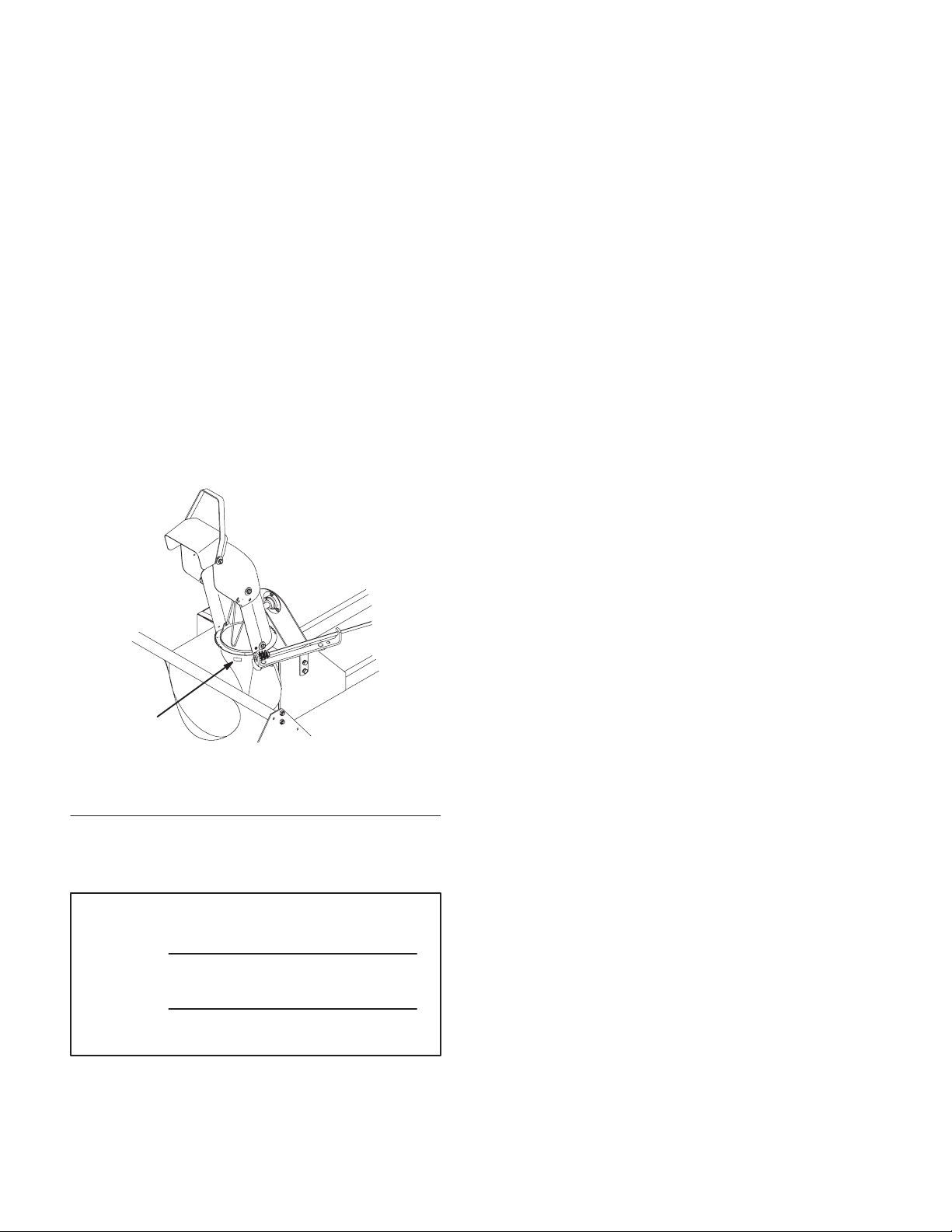
plate located in a unique place on the product as
shown below.
The warning system in this manual identifies
potential hazards and has special safety messages that
help you and others avoid personal injury, even death.
DANGER, WARNING and CAUTION are signal
words used to identify the level of hazard. However,
regardless of the hazard, be extremely careful.
DANGER signals an extreme hazard that will cause
serious injury or death if the recommended
precautions are not followed.
WARNING signals a hazard that may cause serious
injury or death if the recommended precautions are
not followed.
CAUTION signals a hazard that may cause minor or
moderate injury if the recommended precautions are
not followed.
Two other words are also used to highlight
information. “Important” calls attention to special
mechanical information and “Note” emphasizes
general information worthy of special attention.
1
m–3732
Figure 1
1. Model and Serial Number Plate
For your convenience, write the product model and
serial numbers in the space below.
Model No:
Serial No.
The left and right side of the machine is determined
by sitting on the seat in the normal operator’s
position.
Printed in USA
Page 3

Contents
Safety and Instruction Decals 2. . . . . . . . . . . . . .
Installation 3. . . . . . . . . . . . . . . . . . . . . . . . . . . . .
Loose Parts 3. . . . . . . . . . . . . . . . . . . . . . . . .
Assembling the Snowthrower 5. . . . . . . . . .
Setting Up the Tractor 7. . . . . . . . . . . . . . . .
Installing the Snowthrower on the Tractor 7.
Removing the Snowthrower 12. . . . . . . . . . . .
Operation 16. . . . . . . . . . . . . . . . . . . . . . . . . . . . . .
Operating the Power Take Off (PTO) 16. . . .
Operating the Attachment Lift Lever 17. . . . .
Adjusting The Discharge Chute 18. . . . . . . . .
Tips for Throwing Snow 18. . . . . . . . . . . . . .
Page
Page
Maintenance 20. . . . . . . . . . . . . . . . . . . . . . . . . . . .
Service Interval Chart 20. . . . . . . . . . . . . . . .
Greasing and Lubrication 20. . . . . . . . . . . . . .
Replacing the Snowthrower Belt 22. . . . . . . .
Adjusting the Skids 24. . . . . . . . . . . . . . . . . .
Replacing the Scraper Blade 25. . . . . . . . . . .
Adjusting Drive Chain Tension 25. . . . . . . . .
Storage 26. . . . . . . . . . . . . . . . . . . . . . . . . . . .
1
Page 4
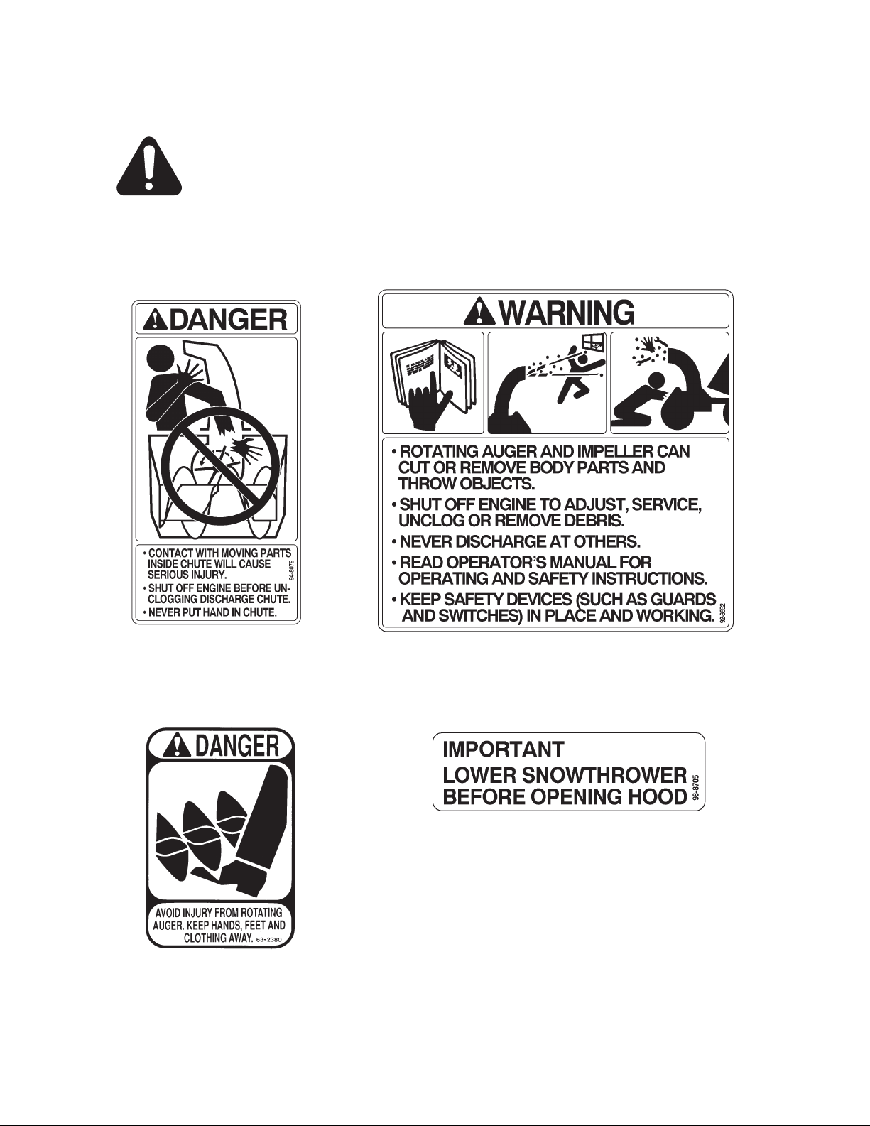
Safety
Safety and Instruction Decals
Safety decals and instructions are easily visible to the operator and are located near
any area of potential danger. Replace any decal that is damaged or lost.
ON UPPER DISCHARGE
CHUTE
(Part No. 94–8079)
ON TOP OF HOUSING
(Part No. 92–8652)
(2) ON TOP OF HOUSING
(Part No. 63–2380)
2
ON TOP OF PULLEY COVER
(Part No. 98–8705)
Page 5

Installation
Loose Parts
Note: A rear–mount Attach-A-Matic hitch, rear wheel weights (and/or rear weight box**) and chains, all of
which must be purchased separately, are required to operate the tractor equipped with this snowthrower.
Use the chart below to identify parts used for assembly.
**Rear wheel weights may not provide adequate traction under some conditions or on inclines. If these
conditions exist, a rear weight box is recommended.
DESCRIPTION QTY. USE
Snowthrower frame assembly
Lift tube
Clevis pin 1/2” x 2 5/8” (67 mm)
Clevis clip
Discharge chute assembly
Washer 5/16” (8 mm)
Locknut 5/16”
Carriage bolt 5/16–18 x 3/4” (19 mm)
Clevis pin 3/8” x 1” (25 mm)
Hairpin cotter—small
Pulley box
Belt
1
1
Attach lift tube
1
1
1
3
Assemble discharge chute
3
3
2
Prepare tractor attachment lift
2
1
Install pulley box
1
3
Page 6

Installation
DESCRIPTION USEQTY.
Clevis pin 1/2” x 1” (25 mm)
Clevis clip
Spring tension link
Support rod link
Support brace
Washer 13/16” (21 mm)
Hairpin cotter—large
Washer 15/16” (24 mm)
Crank support
Locking pin
Chute control rod
Hairpin cotter—small
Hairpin cotter–medium
Pulley cover
Screw #10 x 1/2” (13 mm)
Rod Assembly
Spacer washer 1” (25 mm)
1
1
1
1
2
2
4
2
1
Mount snowthrower to tractor
1
1
3
1
1
4
1
2
“C” shaped pin
Operator’s Manual 1 Read before operating
2
4
Page 7
Installation
Assembling the Snowthrower
Attach Lift Tube
Connect the lift tube to the snowthrower frame
assembly with the 2 5/8” (67 mm) clevis pin and
clip (Fig. 1)
1
4
1. Lift tube
2. Snowthrower frame
assembly
3
2
m–3668d
Figure 1
3. Clevis pin 2 5/8” (67 mm)
4. Clevis clip
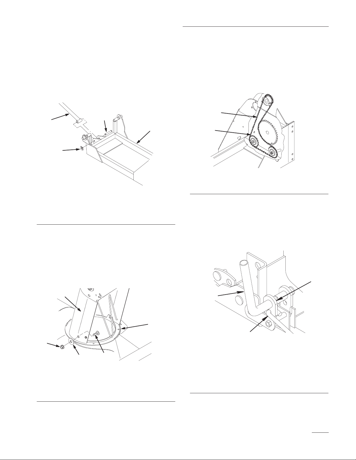
Verify the Drive Chain Tension
Verify that the drive chain has between 1/8” and 1/2”
deflection in the area shown in Figure 3. If the chain
is too tight or too loose, adjust it; refer to Adjusting
Drive Chain Tension, page 25.
2
1
m–3795
Figure 3
1. Drive chain 2. Check deflection here
Assemble Spring Tension Link
Assemble the Discharge Chute
Install the discharge chute assembly onto the
chute ring with (3) 5/16 x 3/4” (19 mm) carriage
bolts (heads to the inside), (3) 5/16” (8 mm)
washers and (3) 5/16” locknuts (Fig. 2).
1
4
3
1. Discharge chute assembly
2. Carriage bolt 5/16 x 3/4”
(19 mm)
2
Figure 2
3. Washer 5/16” (8 mm)
4. Locknut 5/16”
5. Chute ring
Insert the hooked end of the spring tension link
into the open hole in the outer leg of the spring
tension lever (Fig. 4).
3
1
5
2
m–4087
m–3719
1. Spring tension lever
2. Hooked end of spring
tension link
Figure 4
3. Outer leg
5
Page 8
Installation
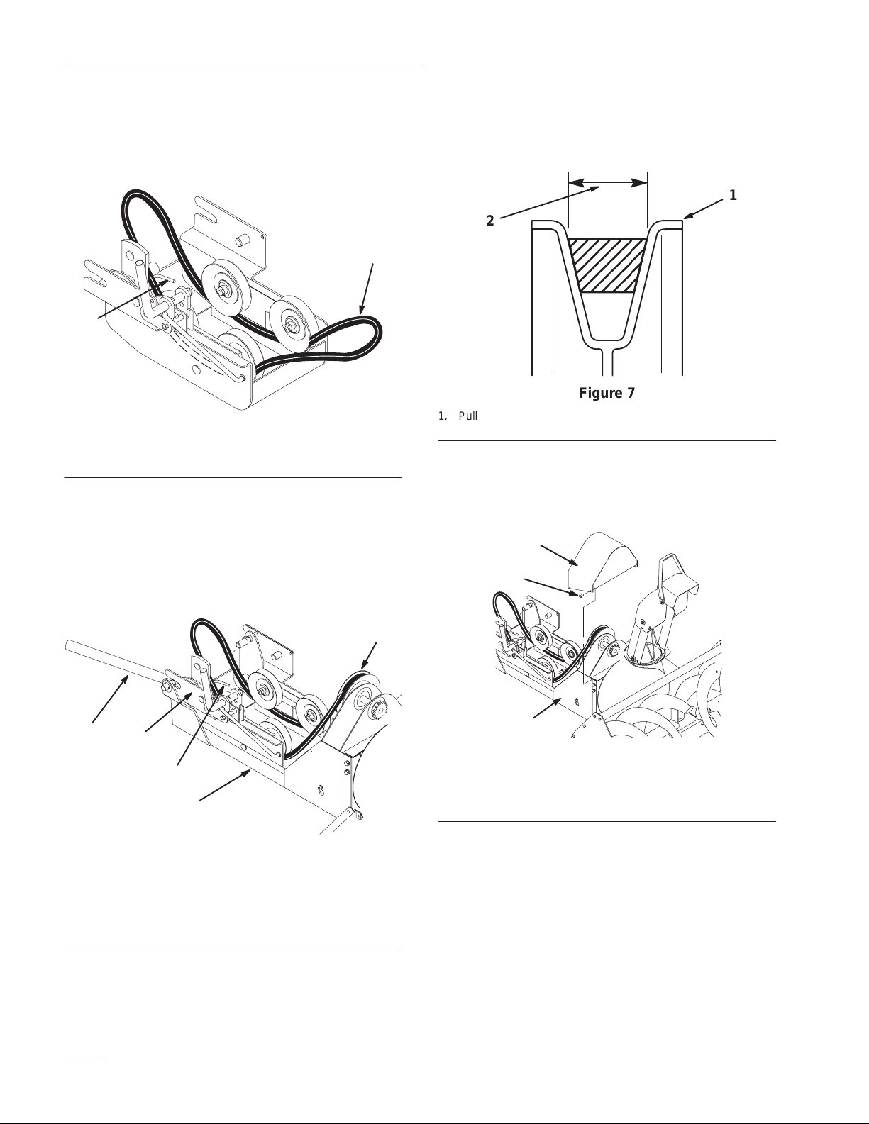
Install Drive Belt and Pulley Cover
1. Route the belt under the four (4) pulleys and
inside the belt guide in the pulley box (Fig. 5).
1
2
m–4348
Figure 5
1. Snowthrower belt 2. Belt guide
2. Slide the pulley box into the snowthrower frame
(Fig. 6).
3. Route the belt over the snowthrower pulley
(Fig. 6).
4. Make certain that the wide side of the PTO drive
belt is toward the outside diameter of all the
pulleys (Fig. 7).
1
2
m–4230
Figure 7
1. Pulley outside diameter 2. Wide side of belt
5. Attach the pulley cover to the snowthrower
frame assembly with (4) #10 x 1/2” (13 mm)
screws (Fig. 8).
1
2
4
3
5
1. Snowthrower frame
2. Snowthrower pulley
3. Pulley box
1
Figure 6
4. Lift tube
5. Belt guide
m–4342
2
3
m–4343
Figure 8
1. Pulley cover
2. Screw #10 x 1/2” (13 mm)
3. Snowthrower frame
assembly
6
Page 9

Setting Up the Tractor
Install Rear Wheel Weights and Chains
Installation
Install the rear wheel weights and chains. Refer to
Attachment Installation Instructions supplied with the
attachment.
Note: Rear wheel weights may not provide
adequate traction under some
conditions or on inclines. If these
conditions exist, a rear weight box is
recommended.
Install the Rear Attach-A-Matic Hitch
Install the rear Attach-A-Matic hitch to the tractor;
refer to the Installation Instructions that come with
the Attach-A-Matic hitch.
Prepare the Tractor’s Attachment Lift
1. Start the engine.
2. Raise the attachment lift.
3. Set the parking brake and turn the ignition key to
“STOP” to stop the engine. Remove the ignition
key.
4. The two lift arms are attached to the tractor
frame, just ahead of the rear wheels. Secure the
lift arms to the tractor frame with 3/8” x 1”
(25 mm) clevis pins and small hairpin cotters
(Fig. 9).
3
2
1
m–3433
Figure 9
Right side of tractor shown
1. Lift arm
2. Clevis pin 3/8” x 1”
(25 mm)
3. Hairpin cotter–small
These pins must be installed when operating with a
blade, snowthrower, or the tiller attachment.
Note: Remove the pins when attaching a
mower.
Installing the Snowthrower on
the Tractor
1. Position the snowthrower frame assembly and its
attachment parts on a level surface with enough
space behind them to accommodate the tractor.
2. Park the tractor behind the snowthrower with the
front wheels lined up to straddle the snowtrower
frame and lift rod (Fig. 10). Lower the
attachment lift and turn the ignition key to
“STOP” to stop the engine. Remove the ignition
key.
7
Page 10

Installation
Figure 10
3. With the High–Low range selector in neutral
“N,” pull the tractor forward toward the
snowthrower until the end of the snowthrower
frame is just underneath the tractor’s front
Attach-A-Matic hitch (Fig. 11).
4. Ensure the latches on the tractor’s front
Attach-A-Matic are open. Then slide the
pulley box completely into the Attach-A-Matic
hitch. Close the latches by rotating them down
(Fig. 11).
2
m–3446
3
2
1
4
m–4345
Figure 12
1. Pulley box
2. “C” shaped pin
3. Attach–A–Matic latch
4. Hairpin cotter–small
6. Now connect the snowthrower frame to the mid
Attach-A-Matic hitch. You will need the crank
support to help with this.
1
m–4344
Figure 11
1. Attach–A–Matic hitch
latches
2. Pulley box
5. Install (2) “C” shaped pins into the locking holes
of the pulley box. Secure them with (2) small
hairpin cotters on the inside (Fig. 12).
A. Continue pulling the tractor toward the
snowthrower until the snowthrower frame
connecting pins are directly below the mid
Attach–A–Matic hitch (Fig. 13)
8
Page 11

Installation
D. Use the crank support as a lever to lift the
snowthrower frame until its connecting pins
are completely inside the notches in the mid
Attach-A-Matic hitch (Fig. 15).
1
2
3
Figure 13
Right side of tractor shown
1. Mid Attach–A–Matic
hitch
2. Snowthrower connecting
pins (right side shown)
3. Snowthrower frame
B. Make sure the mid Attach-A-Matic hitch
latches are open.
C. Slide the round end of the crank support
under the notch in the snowthrower frame
(Fig. 14).
2
m–4401
m–3679
POTENTIAL HAZARD
• The snowthrower frame assembly is heavy.
WHAT CAN HAPPEN
• Hands and feet can be injured by the
weight of the snowthrower coming down on
them.
HOW TO AVOID THE HAZARD
• Keep hands and feet away from the
underside of the snowthrower frame.
E. Turn the mid Attach-A-Matic hitch lever
counterclockwise to lock the snowthrower
in place (Fig. 15).
IMPORTANT: Make sure the snowthrower
frame is locked in place. You should hear a
distinct click if the snowthrower is correctly
mounted.
1
Figure 14
Right side of tractor shown
1. Crank Support 2. Notch in snowthrower
frame
2
1
m–3707
Figure 15
Right side of tractor shown
1. Snowthrower frame 2. Mid Attach-A-Matic
hitch lever
F. Set the parking brake.
9
Page 12

Installation
7. Add (2) 1” (25 mm) washers onto the end of the
rod assembly, then slide it into the lift tube
(Fig. 16).
1
1. Rod assembly
2. Lift tube
3
2
m–3450
Figure 16
3. Washers 1” (25 mm)
Note: A washer may need to be removed
from the rod assembly for the holes to
line up with the attachment lift plate.
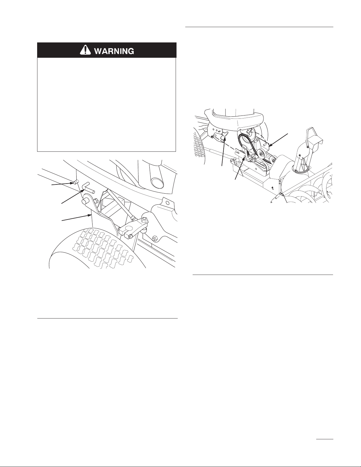
8. From beneath the tractor, connect the
snowthrower rod assembly to the middle hole in
the attachment lift plate (lift plate goes between
the rod assembly plates) with the 1” (25 mm)
clevis pin and clip (Fig. 17).
9. Now install the snowthrower belt to the engine
PTO pulley:
A. Open the hood of the tractor
B. Remove the right–hand side panel.
POTENTIAL HAZARD
• Components under the hood will be hot if
the tractor has been running.
WHAT CAN HAPPEN
• Touching hot components can cause burns.
HOW TO AVOID THE HAZARD
• Allow the tractor to cool before performing
maintenance or touching components
under the hood.
C. Route the snowthrower belt around the
engine PTO pulley (Fig. 18).
Note: Lifting up on the spring–loaded pulley
will ease installation of the belt.
4
Right side of tractor shown
1. Middle h o l e in attachment
lift plate
2. Snowthrower rod
assembly
3
1
2
Figure 17
3. Clevis pin 1/2” x 1”
4. Clevis clip
5. Attachment lift plate
(25 mm)
End view
m–3661
5
1
3
2
4
2
m–3696d
Figure 18
1. Engine PTO pulley
2. Snowthrower pulley
3. Belt
4. Spring –loaded pulley
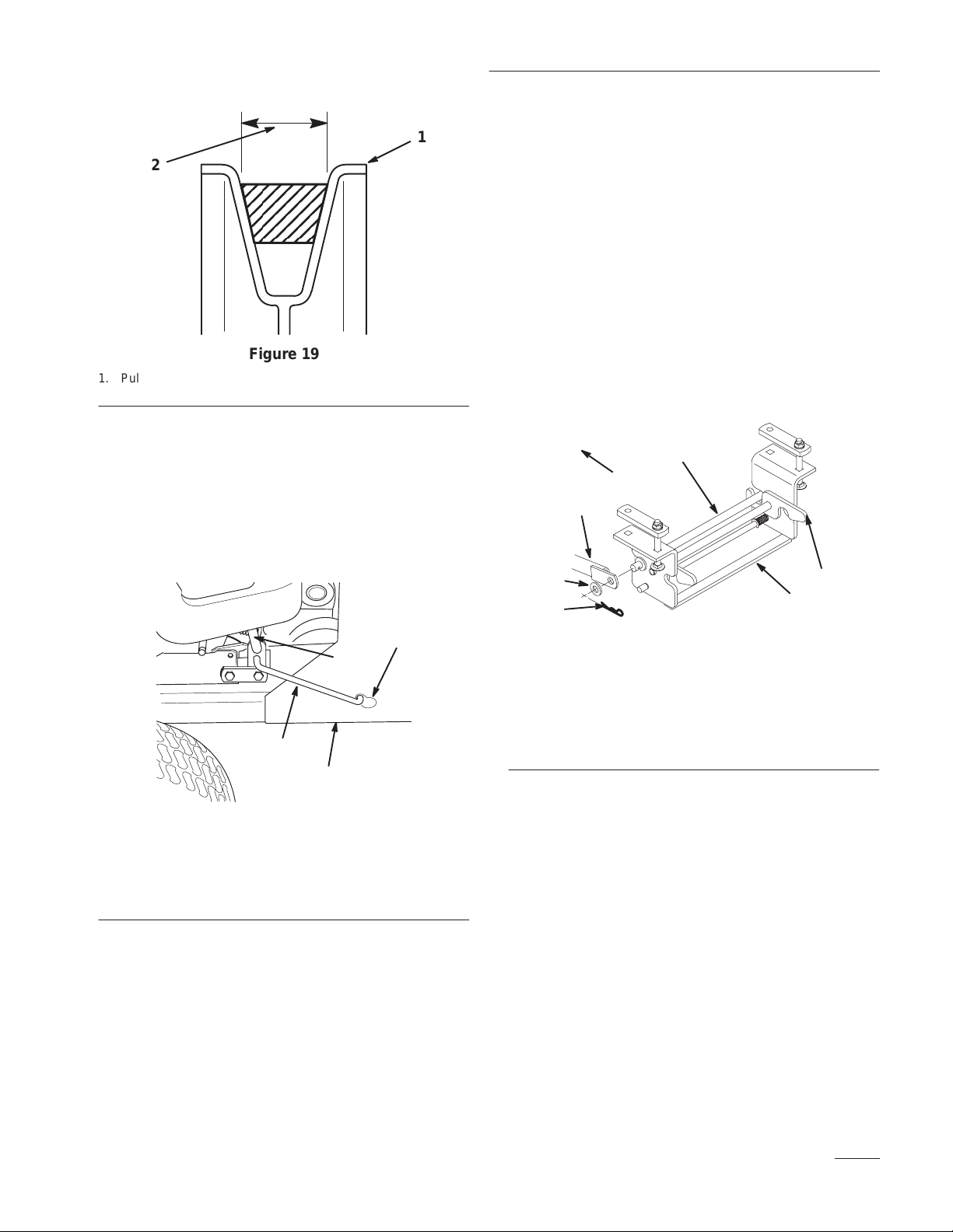
10. Make certain that the wide side of the PTO drive
belt is toward the outside diameter of all (six)
pulleys (Fig. 19).
10
Page 13
Installation
12. Open the latches on the rear Attach-A-Matic
1
2
hitch. Put the support rod link into the front
notches on the rear Attach-A-Matic hitch and
close the latches to secure it in place (Fig. 21).
13. Slide the non adjusting ends of the two support
braces onto the support rod link that is now in
the rear Attach-A-Matic hitch mount.
• Make sure the rod of each brace faces
m–4230
inward.
Figure 19
1. Pulley outside diameter 2. Wide side of belt
A. Replace the right side panel and close the
hood.
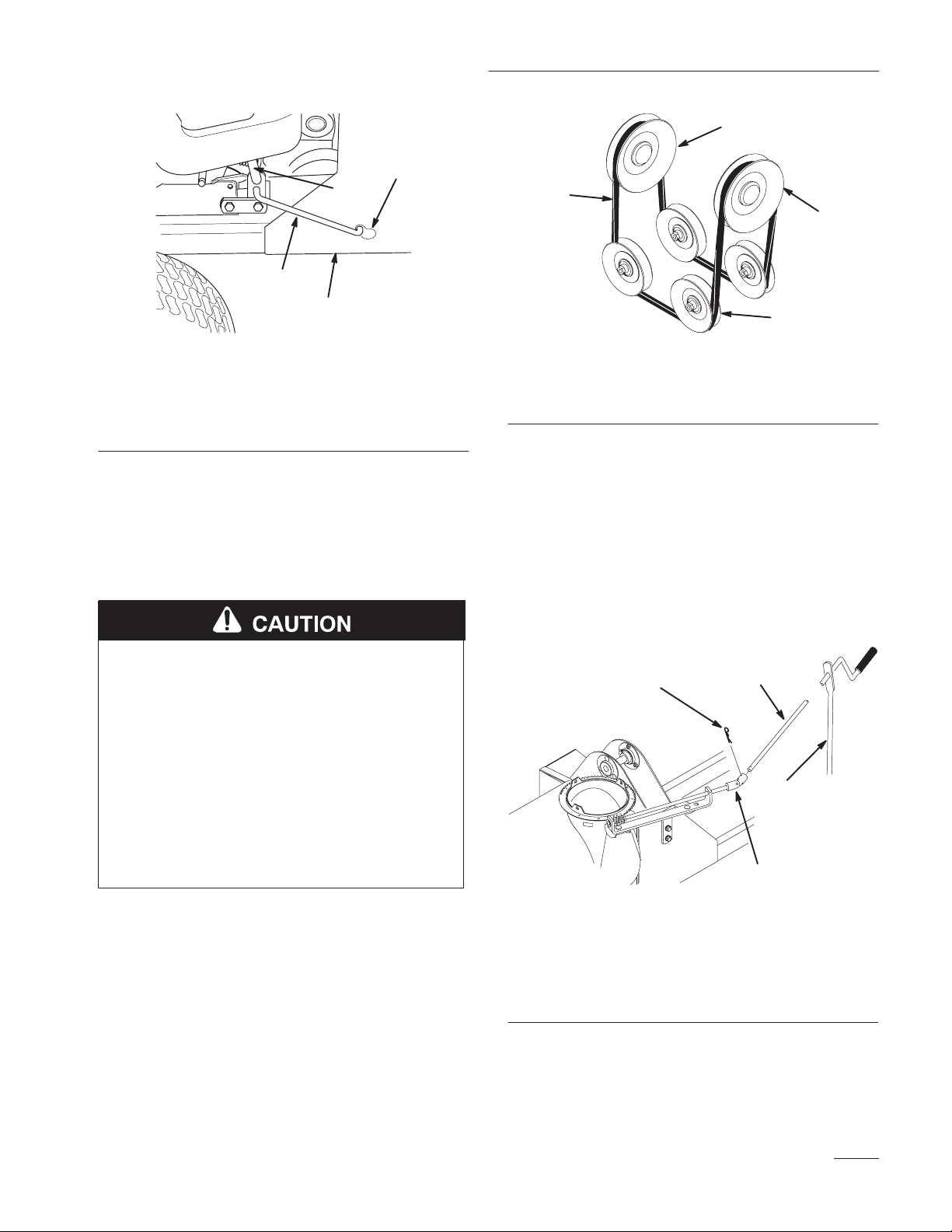
11. On the right side of the tractor, pull forward on
the spring tension lever and connect the spring
tension link to the keyhole slot in the
snowthrower frame (Fig. 20).
4
2
Right side of tractor shown
1. Spring tension link
2. Spring tension lever
1
3
Figure 20
3. Snowthrower frame
4. Keyhole slot
m–4346
• Secure the braces to the rod with a 13/16”
(21 mm) washer and a large hairpin cotter
(Fig. 21).
1
3
5
6
7
4
m–3724
2
Figure 21
1. Support rod link
2. Rear Attach–A–Matic
hitch
3. Front of tractor
4. Rear Attach–A–Matic
hitch latch
5. Support brace
6. Washer 13/16” (21 mm)
7. Hairpin cotter–large
14. Secure the other ends of the support braces to the
frame rods protruding from the mid
Attach-A-Matic hitch with a 15/16” (24 mm)
washer and a large hairpin cotter (Fig. 22). You
may need to turn the adjuster of each brace
before the holes in the adjuster align with the
frame rod.
11
Page 14

Installation
Left side of tractor shown
1. Support brace
2. Washer, 15/16” (24mm)
3. Hairpin cotter–large
4
Figure 22
4. Mounting post for crank
2
3
support
1
m–3681
16. Slide the chute control rod through the hole in
the end of the crank support and connect the end
of the chute control rod to the universal joint on
the snowthrower with a medium hairpin cotter
(Fig. 24).
4
1
2
15. Slide the crank support onto the mounting post
on the left–hand side of the tractor (Fig. 22).
Secure it in position with a locking pin and small
hairpin cotter (Fig. 23).
1
2
3
m–4347
Figure 23
Left side of tractor shown
1. Crank support
2. Locking pin
3. Hairpin cotter–small
3
m–4349
Figure 24
1. Chute control rod
2. Crank support
3. Universal joint
4. Hairpin cotter–medium
Removing the Snowthrower
1. Park the tractor on a level surface, lower the
attachment lift, disengage the power take off
(PTO), set the parking brake and turn the
ignition key to “STOP” to stop the engine.
Remove the ignition key.
2. Relieve the snowthrower belt tension by pulling
the spring tension lever forward until you have
enough slack to disconnect the link from the
keyhole slot (Fig. 25).
12
Page 15
Installation
1
4
2
3
2
1
m–4346
3
Figure 25
Right side of tractor shown
1. Spring tension link
2. Spring tension lever
3. Snowthrower frame
4. Keyhole slot
3. Remove the snowthrower belt from the engine
PTO pulley:
A. Open the hood of the tractor
B. Remove the right–hand side panel.
POTENTIAL HAZARD
• Components under the hood will be hot if
the tractor has been running.
4
m–3696d
Figure 26
1. Engine PTO pulley
2. Snowthrower pulley
3. Belt
4. Spring–loaded pulley
D. Replace the right side panel and close the
hood.
4. Remove the chute control rod by removing the
hairpin cotter connecting it to the universal joint
(Fig. 27). Slide the chute control rod out of the
end of the crank support.
4
1
WHAT CAN HAPPEN
• Touching hot components can cause burns.
HOW TO AVOID THE HAZARD
• Allow the tractor to cool before performing
maintenance or touching components
under the hood.
C. Remove the snowthrower belt from around
the engine PTO pulley (Fig. 26).
Note: Lifting up on the spring–loaded pulley
will ease removal of the belt.
2
3
m–4349
Figure 27
1. Chute control rod
2. Crank support
3. Universal joint
4. Hairpin cotter–medium
5. Remove the crank support by removing the
hairpin cotter and clevis pin at its base (Fig. 28),
then lifting the support from its mounting post.
13
Page 16

Installation
6. Remove the support braces from the frame rods
protruding from the mid Attach-A-Matic hitch
by removing the hairpin cotters and washers
(Fig. 28).
1
3
5
1
3
2
4
m–3681
Figure 28
Left side of tractor shown
1. Support brace assembly
2. Washer, 15/16” (24mm)
3. Hairpin cotter–large
4. Mounting post for crank
support
7. Remove the other ends of the two support braces
from the rear Attach-A-Matic hitch mount by
removing the hairpin cotters and washers
(Fig. 29).
8. Release the latches on the rear Attach-A-Matic
hitch and remove the support rod link (Fig. 29).
6
7
4
m–3724
2
Figure 29
1. Support rod link
2. Rear Attach–A–Matic
hitch
3. Front of tractor
4. Rear Attach–A–Matic
hitch latch
5. Support brace
6. Washer 13/16” (21 mm)
7. Hairpin cotter–large
9. Disconnect the snowthrower lift rod from the
attachment lift plate by removing the clevis clip
and clevis pin (Fig. 30).
3
1
4
2
5
2
14
m–3661
Figure 30
Right side of tractor shown
1. Middle hole in attachment
lift plate
2. Snowthrower lift rod
3. Clevis pin 1/2” x 1”
(25 mm)
4. Clevis clip
5. Attachment lift plate
10. Press the button of the mid Attach-A-Matic
hitch and carefully turn the lever clockwise to
release the snowthrower (Fig. 31). Please use
CAUTION during this step! The snowthrower
frame will drop to the ground.
Page 17
POTENTIAL HAZARD
• The snowthrower frame assembly is heavy.
WHAT CAN HAPPEN
• Hands and feet can be injured by the
weight of the snowthrower coming down on
them.
HOW TO AVOID THE HAZARD
• Keep hands and feet away from the
underside of the snowthrower frame.
Installation
14. Install the “C” shaped pins into the locking holes
of the pulley box for storage. Retain with the
hairpin cotters.
2
1
3
2
1
m–3707
Figure 31
Right side of tractor shown
1. Snowthrower frame
2. Mid Attach-A-Matic hitch
lever
3. Mid Attach-A-Matic
hitch button
11. Put the tractor ’s High–Low range lever in neutral
“N” and release the parking brake.
12. Push the tractor back, away from the
snowthrower until there is sufficient space to
remove the pulley box.
3
Figure 32
1. Attach–A–Matic hitch
latches
2. Pulley box
3. Locking holes
15. Push the tractor back, away from the
snowthrower frame. Set the parking brake.
m–4344
13. Remove the “C” shaped pins from the pulley
box locking holes (Fig. 32). Open the latches of
the front Attach-A-Matic hitch, remove the
pulley box, and slide it into snowthrower frame.
15
Page 18

Operation
POTENTIAL HAZARD
• When the snowthrower is attached to the
tractor, without additional weight, the
tractor may become unstable.
WHAT CAN HAPPEN
• Loss of traction and stability may cause
loss of tractor control.
HOW TO AVOID THE HAZARD
• NEVER operate the tractor equipped with
the snowthrower, unless rear weights are
installed.
Operating the Power Take Off
(PTO)
The power take–off (PTO) switch engages and
disengages power to the electric clutch.
If the ignition key is in the RUN or LIGHTS position
and the power take off (PTO) is engaged, the PTO
indicator light will be on. When this light is on, it is a
reminder: the implement is being powered and the
starter will not crank while the PTO is engaged.
Always turn off the PTO before getting off the seat.
Engaging the Power Take Off (PTO)
1. Depress the brake pedal to stop the machine.
2. Move the throttle lever to FAST.
POTENTIAL HAZARD
• Rotating auger can cut off fingers, hands or
other body parts and throw objects.
WHAT CAN HAPPEN
• Contact with rotating auger and thrown
debris can cause severe injury or death.
HOW TO AVOID THE HAZARD
• Stay away from the discharge and auger
openings while operating the snowthrower.
• Keep your hands, feet, and any other part
of your body or clothing away from
concealed, moving or rotating parts.
• Use a stick, not your hand, to remove
obstructions from the discharge chute or
auger housing.
• Before adjusting, cleaning, repairing and
inspecting the snowthrower and before
unclogging the discharge chute, shut off the
engine and wait for all moving parts to
stop. Move the power take off (PTO) to
“OFF” and rotate the ignition key to
“OFF.” Remove the key.
IMPORTANT: For best performance, always
use full throttle when the power take off
(PTO) switch is ON.
3. Pull the power take off (PTO) switch to ON (Fig.
33).
1
Figure 33
1. Push (of f-disengaged) 2. Pull (on-engaged)
2
m–3264
Disengaging the Power Take Off (PTO)
16
1. Push the power take off (PTO) switch to OFF.
Page 19
Operation
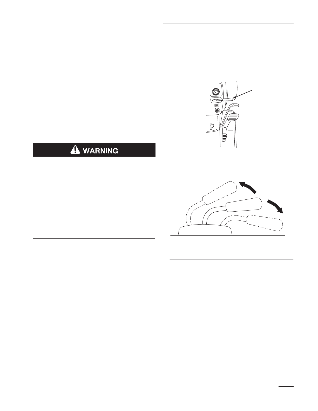
Operating the Attachment Lift
Lever
The attachment lift lever (Fig. 34 & 35) is used to
raise and lower various attachments.
Raising Attachments
1. Start the tractor.
2. Pull the attachment lift lever upward until the
latch locks. In this position, the lift will hold the
attachment in the up, or raised position.
POTENTIAL HAZARD
• When the engine is off, attachments in the
raised position can gradually lower.
WHAT CAN HAPPEN
• Someone nearby may be pinned or injured
by the attachment as it lowers.
Lowering Attachments
1. Start the tractor.
2. Push the attachment lift lever downward to
lower the attachment.
1
m–3258
Figure 34
1. Attachment lift lever
1
2
HOW TO AVOID THE HAZARD
• Always lower the attachment lift each time
you shut off the tractor.
IMPORTANT: The tractor hood must be
closed before the snowthrower is raised.
m–3315
Figure 35
1. Raise attachment 2. Lower attachment
17
Page 20

Operation
Adjusting The Discharge Chute
POTENTIAL HAZARD
• The rotating auger can cut off fingers,
hands or other body parts and throw
objects.
WHAT CAN HAPPEN
• Contact with the rotating auger and thrown
debris can cause sever injury or even death.
HOW TO AVOID THE HAZARD
• Stay away from the discharge and auger
openings while operating the snowthrower.
• Keep your hands, feet, and any other parts
of your body or clothing away from
concealed, moving or rotating parts.
• Use a stick, not you hand, to remove
obstructions from the discharge chute or
auger housing.
• Before adjusting, cleaning, repairing and
inspecting the snowthrower and before
unclogging the discharge chute, shut off the
engine and wait for all moving parts to
stop. Move the power take off (PTO) to
“OFF” and rotate the ignition key to
“OFF.” Remove the key.
3
1
2
m–1290a
1. Discharge chute
2. Crank handle
m–3445
Figure 36
3. Chute deflector
Tips for Throwing Snow
Remove snow as soon as possible after it falls. This
produces best snow removal results.
Adjust the skids to match the type of surface being
cleaned; refer to Adjusting the Skids, page 24.
The snowthrower is designed to clean snow down to
the contact surface, but there are times when the front
of the snowthrower may tend to ride up. If this
happens, reduce forward speed.
Discharge snow downwind whenever possible, and
overlap each pass to ensure complete snow removal.
If the wheels slip, shift into the High–Low range
lever to Low “L” to reduce forward speed.
The discharge chute can be rotated 180° side to side.
The direction is controlled by turning the crank
handle (Fig. 36).
The chute deflector, on top of the discharge chute, can
be moved up and down to control the height and
distance snow is thrown (Fig. 36).
18
Run the snowthrower for a few minutes after clearing
snow so moving parts do not freeze. Engage the
power take off (PTO) to clear any remaining snow
from the inside housing.
Do not overload the snowthrower by clearing snow at
too fast a rate. If the engine slows down, reduce
forward speed.
Always use full throttle (maximum engine speed)
when throwing snow.
Page 21

In wet or slushy conditions, clogging of the discharge
chute will be reduced by maintaining maximum
engine speed and by not overloading the engine.
In some snow and cold weather conditions, some
controls and moving parts may freeze. Therefore,
when any control becomes hard to operate, stop the
machine and wait for all moving parts to stop; then
check all parts for freeze up. DO NOT USE
EXCESSIVE FORCE AND TRY TO OPERATE
THE CONTROLS WHEN FROZEN. Free all
controls and moving parts before operating.
Use low range (on the high–low range lever) for best
performance and smoothest operation.
Operation
19
Page 22

Maintenance
Service Interval Chart
Each
Service Operation
Drive shaft bearings—grease X X X
Drive chain—oil X X X
Gear box lubricant—check X X X
Belt—check for wear/cracks X X
Chipped Surfaces—paint X
Scraper—check for wear X X
Drive chain—adjust tension X
POTENTIAL HAZARD
Use5Hours25Hours
Storage
Service
Fall
Service
• If you leave the key in the ignition switch, someone could start the engine.
WHAT CAN HAPPEN
• Accidental starting of the engine could seriously injure you or other bystanders.
HOW TO AVOID THE HAZARD
• Remove the key from the ignition switch and pull the wire(s) off the spark plug(s)
before you do any maintenance. Also push the wire(s) aside so it does not
accidentally contact the spark plug(s).
Notes
Greasing and Lubrication
Service Interval Specification
Grease and oil the machine after every 25 operating
hours or once a year, whichever occurs first.
Grease Type: General–purpose grease.
Oil Type: SAE 10W or l0W30.
20
How to Grease
1. Disengage the power take off (PTO), set the
parking brake, lower the attachment lift, and turn
the ignition key to “STOP” to stop the engine.
Remove the key.
2. Clean the grease fittings with a rag. Make sure
to scrape any paint off the front of the fitting(s).
3. Connect a grease gun to the fittings. Pump
grease into the fittings. Wipe up any excess
grease.
Page 23

Maintenance
Where to Add Grease
1. Lubricate the jack shaft bearings (Fig. 37) and
drive bearings (Fig. 38).
m–3737
Figure 37
Oil the Drive Chain
1. Disengage the power take off (PTO), set the
parking brake, lower the attachment lift, and turn
the ignition key to “STOP” to stop the engine.
Remove the key.
2. Coat the entire chain with oil and allow it to
penetrate each roller (Fig. 39).
3. Place a few drops of oil on the discharge chute
rotator shaft and discharge chute mounting
(Fig. 40).
4. Wipe off excess oil.
Figure 38
m–3723
Figure 39
m–3723
m–3732
Figure 40
21
Page 24

Maintenance
Check Gear Box Lubricant
1. Move the snowthrower to a level surface.
Disengage the power take off (PTO), set the
parking brake, lower the attachment lift, and turn
the ignition key to “OFF” to stop the engine.
Remove the key.
2. Clean area around plug with a rag and remove
plug (Fig. 41).
3. Add SAE 90 gear oil until level with bottom of
hole in housing (Fig. 41).
4. Apply pipe sealant to the plug and reinstall.
2. Relieve the snothrower belt tension by pulling
the spring tension lever forward until you have
enough slack to disconnect the link from the
keyhole slot (Fig. 42).
4
2
Right side of tractor shown
1. Spring tension link
2. Spring tension lever
1
3
Figure 42
3. Snowthrower frame
4. Keyhole slot
m–4346
1
m–2362
Figure 41
1. Plug
Replacing the Snowthrower
Belt
Removing Belt
Once each year, examine the drive belt for signs of
wear and cracking. If any are found, purchase a belt
from an Authorized Service Dealer and replace it as
follows:
1. Move the snowthrower to a level surface.
Disengage the power take off (PTO), set the
parking brake, lower the attachment lift, and turn
the ignition key to “OFF” to stop the engine.
Remove the ignition key.
3. Remove the pulley cover from the snowthrower
frame assembly, by removing the (4) #10 x 1/2”
(13 mm) screws (Fig. 43).
1
2
3
m–4343
Figure 43
1. Pulley cover
2. Screw #10 x 1/2” (13 mm)
3. Snowthrower frame
assembly
22
Page 25
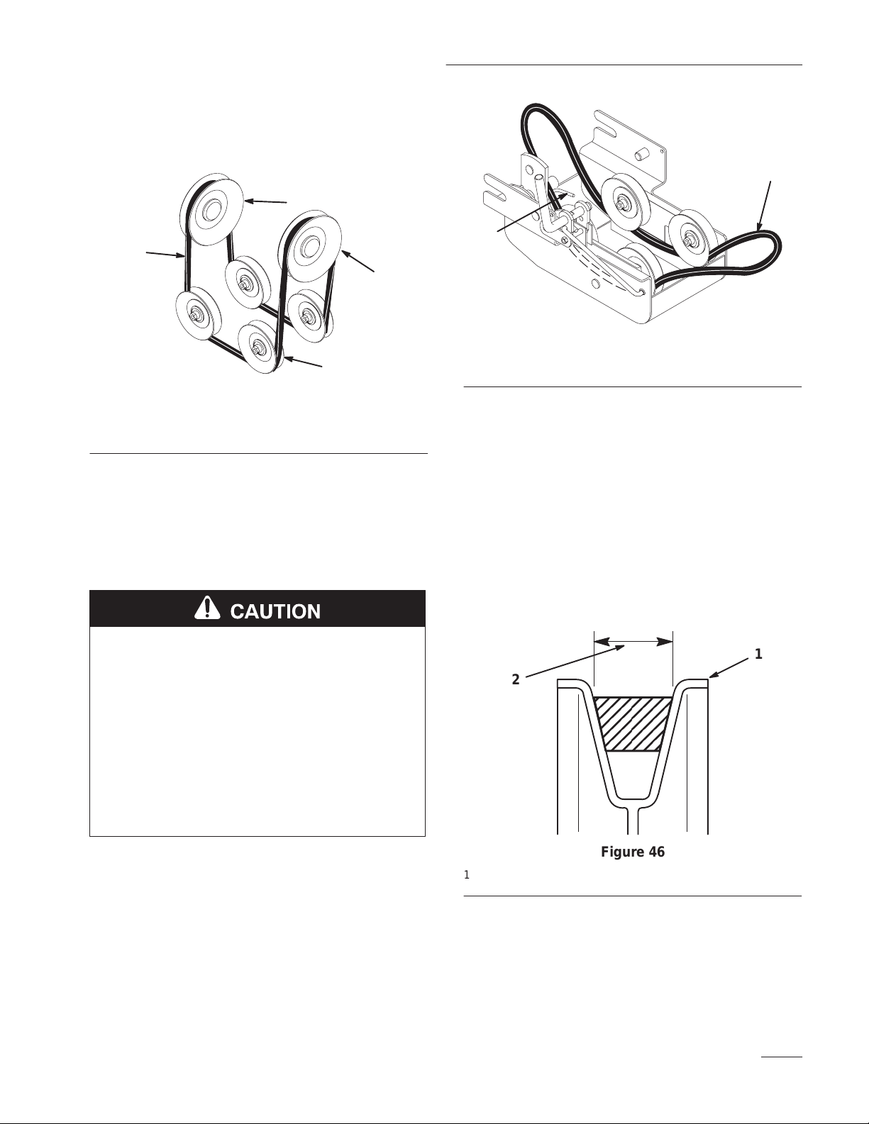
4. Lift up on the spring–loaded pulley and remove
the snowthrower belt from the snowthrower
pulley (Fig. 44).
1
3
2
m–3696d
1. Engine PTO pulley
2. Snowthrower pulley
4
Figure 44
3. Belt
4. Spring –loaded pulley
5. Remove the snowthrower belt from the engine
PTO pulley:
A. Open the hood of the tractor.
Maintenance
1
2
m–4348
Figure 45
1. Snowthrower belt 2. Belt guide
2. Route the snowthrower belt around the engine
PTO pulley.
3. Replace the right side panel and close the hood.
4. Lift up on the spring–loaded pulley and route the
snowthrower belt around the snowthrower
pulley.
B. Remove the right–hand side panel.
POTENTIAL HAZARD
• Components under the hood will be hot if
the tractor has been running.
WHAT CAN HAPPEN
• Touching hot components can cause burns.
HOW TO AVOID THE HAZARD
• Allow the tractor to cool before performing
maintenance or touching components
under the hood.
C. Remove the snowthrower belt from around
the engine PTO pulley (Fig. 44).
Installing Belt
1. Route the new snowthrower belt under the
pulleys and inside the belt guide (Fig. 45).
5. Make certain that the wide side of the PTO drive
belt is toward the outside diameter of all six (6)
of the pulleys (Fig. 46).
1
2
m–4230
Figure 46
1. Pulley outside diameter 2. Wide side of belt
6. On the right side of the tractor, pull forward on
the spring tension lever and connect the spring
tension link from the spring tension lever on the
pulley housing to the keyhole slot in the
snowthrower frame (Fig. 42).
23
Page 26
Maintenance
7. Attach the pulley cover to the snowthrower
frame assembly with (4) # 10 x 1/2” (13 mm)
screws (Fig. 43)
Adjusting the Skids
The distance between the scraper blade and the
ground is controlled by skids on each side of the
housing. The height can be adjusted so the scraper
blade will not catch on uneven surfaces
1. Move the snowthrower to a level surface.
2
3
2. Disengage the power take off (PTO) and set the
parking brake. Raise the attachment lift enough
for the skids to clear the ground. Support the
snowthrower housing off the ground. Turn the
ignition key to “STOP” to stop the engine.
Remove the ignition key.
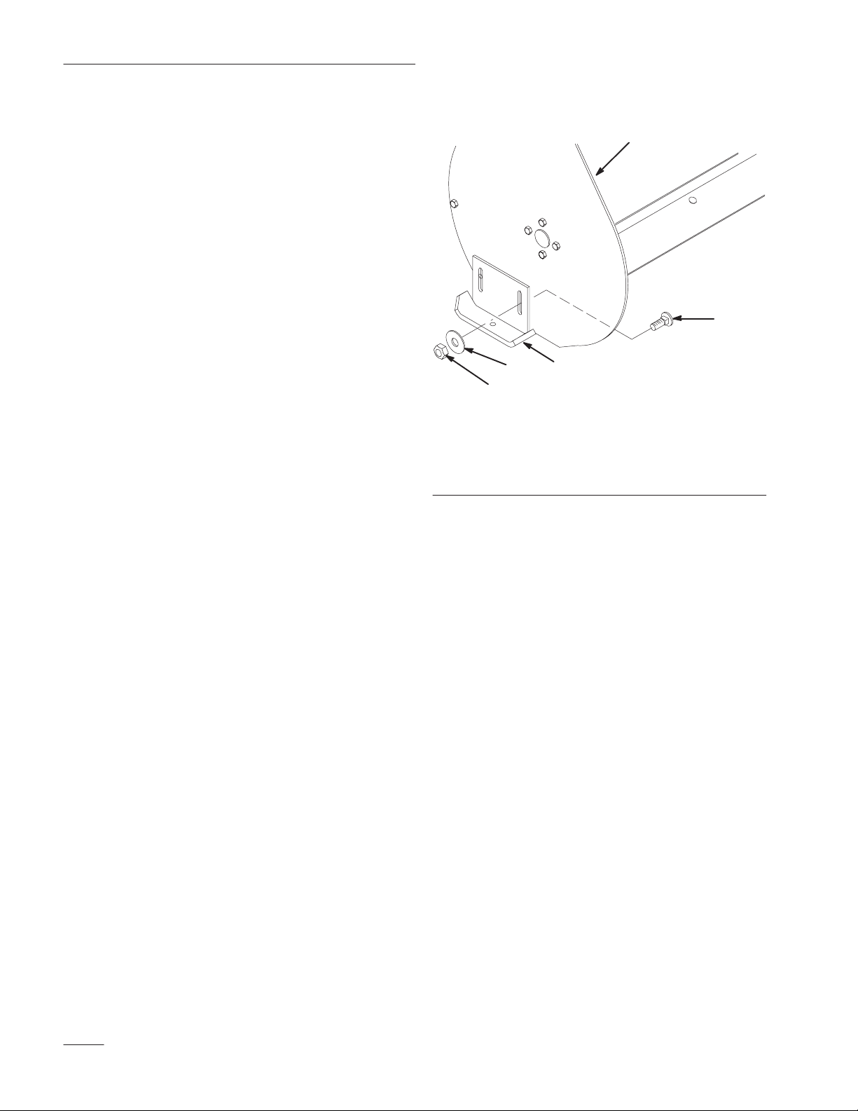
3. Loosen the nuts securing the skids to the housing
until the skids slide up and down easily
(Fig. 47).
4. Raise or lower the skids equally on both sides to
obtain level scraping action, and tighten nuts
securely (Fig. 47).
Note: On smooth, paved surfaces, the scraper
blade can be close to the surface. On
uneven, gravel or crushed rock
surfaces, adjust the skids to raise the
scraper, thereby preventing catching or
picking up rocks.
4
5
1. Skid
2. Housing
3. Carriage bolt, 5/16” x 1
1
Figure 47
4. Flat washer
5. 5/16” nut
IMPORTANT: The scraper should be higher
above the pavement if the pavement surfaces
on which the snowthrower will be used are
cracked, rough or uneven.
m–3745
24
Page 27
Maintenance
Replacing the Scraper Blade
The scraper blade contacts the ground preventing
damage to the snowthrower housing. Periodically
inspect the scraper blade for wear. When scraper
becomes worn, before working surface contacts the
housing, replace the scraper blade.
1. Disengage the power take off (PTO), set the
parking brake, raise the attachment lift, and turn
the ignition key to “STOP” to stop the engine.
Remove the ignition key.
2. Support the snowthrower housing off the
ground.
3. Remove nuts, washers, carriage bolts and scraper
blade (Fig. 48).
4. Replace scraper blade and install with previously
removed hardware (Fig. 48).
Adjusting Drive Chain Tension
Check the drive chain tension after every 25 operating
hours or once a year, whichever occurs first. Adjust as
necessary to maintain proper tension.
1. Disengage the power take off (PTO), set the
parking brake, lower the attachment lift, and turn
the ignition key to “STOP” to stop the engine.
Remove the ignition key.
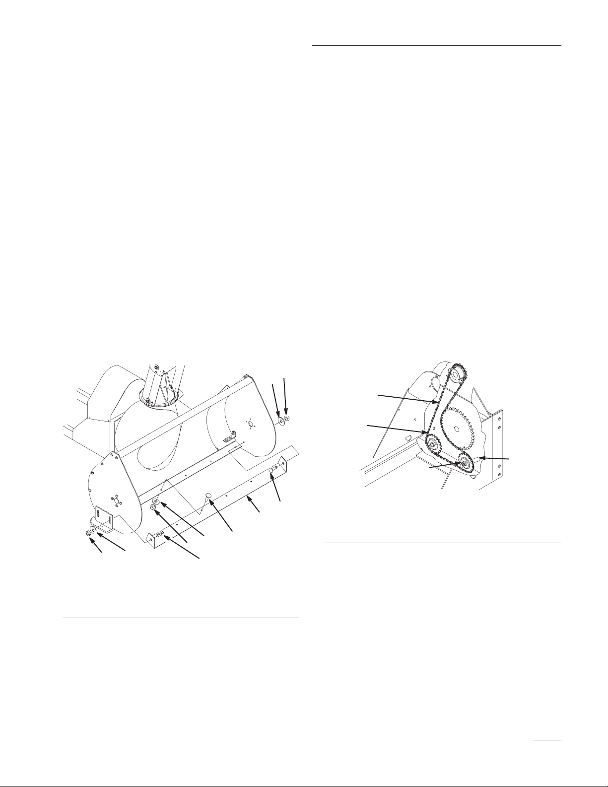
2. To adjust, loosen the nut that secures the idler
sprocket. (Fig. 49).
3. Slide the idler sprocket in the adjustment slot
until the chain is snug, but not tight (1/8” to 1/2”
deflection of the chain in the area indicated in
Figure 49) and torque the nut securing the
sprocket to 67 to 83 ft lbs (90.8 to 112.5 Nm).
IMPORTANT: Do not overtighten the chain
or excessive wear will occur.
1. Nut
2. Washer
1
2
4
1
2
3
4
3
2
2
3
Figure 48
1
3
3. Carriage bolt
4. Scraper blade
m–3722
1. Drive chain
2. Idler sprocket
Figure 49
3. Adjustment slot
4. Check deflection here
3
m–3795
25
Page 28

Maintenance
Storage
1. Before long–term storage, wash the machine
with mild detergent and water to remove dirt and
grime from the entire machine.
2. Check the condition of the scraper blade; refer to
Replacing the Scraper Blade, page 25.
3. Check the condition of the drive belt and chain.
4. Grease and oil the snowthrower; refer to
Greasing and Lubrication, page 20.
5. Check and tighten all bolts, nuts, and screws.
Repair or replace any part that is damaged or
defective.
6. Paint all scratched or bare metal surfaces. Paint
is available from your Authorized Service
Dealer.
7. Coat the inside auger housing and discharge
chute with automotive wax to prevent rust and
reduce the sticking of snow to these surfaces.
8. Store the machine in a clean, dry garage or
storage area. Cover the machine to protect it and
keep it clean.
26
 Loading...