

Page 1

Form No. 3326–603
48 inch Snow/Dozer Blade
Wheel Horse 300 Series Classic Garden
Tractor Attachment
Model No. 79364—220000001 and Up
Operator’s Manual
Domestic English (EN)
Page 2
Contents
Page
Introduction 2. . . . . . . . . . . . . . . . . . . . . . . . . . . . . . . .
Assembly 3. . . . . . . . . . . . . . . . . . . . . . . . . . . . . . . . . .
Loose Parts 3. . . . . . . . . . . . . . . . . . . . . . . . . . . . . .
Assembling the Blade 3. . . . . . . . . . . . . . . . . . . . .
Mounting the Rear Hitch on the Tractor 4. . . . . . .
Installing Blade to Tractor 5. . . . . . . . . . . . . . . . . .
Removing the Blade 6. . . . . . . . . . . . . . . . . . . . . . .
Operation 7. . . . . . . . . . . . . . . . . . . . . . . . . . . . . . . . . .
Raising and Lowering the Blade 7. . . . . . . . . . . . .
Adjusting Dial-A-Height 8. . . . . . . . . . . . . . . . . . .
Adjusting the Blade Angle 8. . . . . . . . . . . . . . . . . .
Adjusting the Blade Trip Springs 8. . . . . . . . . . . .
Tips for Using the Blade 8. . . . . . . . . . . . . . . . . . .
Maintenance 9. . . . . . . . . . . . . . . . . . . . . . . . . . . . . . . .
Recommended Maintenance Schedule 9. . . . . . . .
Greasing and Lubrication 9. . . . . . . . . . . . . . . . . . .
Reversing the Scraper Blade 10. . . . . . . . . . . . . . . .
Storage 10. . . . . . . . . . . . . . . . . . . . . . . . . . . . . . . . .
Introduction
Thank you for purchasing a Toro product.
All of us at Toro want you to be completely satisfied with
your new product, so feel free to contact your local
Authorized Service Dealer for help with service, genuine
replacement parts, or other information you may require.
Whenever you contact your Authorized Service Dealer or
the factory, always know the model and serial numbers of
your product. These numbers will help the Service Dealer
or Service Representative provide exact information about
your specific product. You will find the model and serial
number plate at the location shown in Figure 1.
For your convenience, write the product model and serial
numbers in the space below.
Model No:
Serial No.
Read this manual carefully to learn how to operate and
maintain your product correctly. Reading this manual will
help you and others avoid personal injury and damage to
the product. Although we design, produce and market
safe, state-of-the-art products, you are responsible for
using the product properly and safely. You are also
responsible for training persons, who you allow to use the
product, about safe operation.
The warning system in this manual identifies potential
hazards and has special safety messages that help you and
others avoid personal injury, even death. Danger,
Warning, and Caution are signal words used to identify
the level of hazard. However, regardless of the hazard, be
extremely careful.
Danger signals an extreme hazard that will cause serious
injury or death if the recommended precautions are not
followed.
Warning signals a hazard that may cause serious injury or
death if the recommended precautions are not followed.
Caution signals a hazard that may cause minor or
moderate injury if the recommended precautions are not
followed.
Two other words are also used to highlight information.
Important calls attention to special mechanical
information, and Note emphasizes general information
worthy of special attention.
Determine the left and right side of the machine from the
normal operating position.
Figure 1
1. Model and serial number plate
2001 by The Toro Company
8111 Lyndale Avenue South
Bloomington, MN 55420-1196
m–1237
1
All Rights Reserved
2
Printed in the USA
Page 3

Setup
Loose Parts
Note: Use the chart below to identify parts used for assembly.
DESCRIPTION QTY. USE
Blade assembly
Rod
Control rod
Cotter pin, 1/8 x 1 in.
Frame assembly
Bolt, 3/4-16 x 3-3/4 in.
Locknut, 3/4-16 in.
Hairpin cotter, large
Bolt, 1/2-13 x 1 in
Jam nut, 1/2-13 in.
Cable
Bolt, 1/4 x 1 in.
Locknut, 1/4-20 in.
Cable clip
Cable bracket
Cotter pin, 1-1/4 in.
Rear hitch assembly
Strap
Angle bracket (if required)
Carriage bolt, 3/8-16 x 3-1/2 in.
Locknut, 3/8-16 in.
1
1
1
3
1
1
1
1
1
1
1
3
3
3
1
1
1
2
2
4
4
Assembling the blade
Mounting the rear hitch to the tractor
Lift link
Clevis pin, 3/8 x 7/8 in.
Hairpin cotter, medium
Assembling the Blade
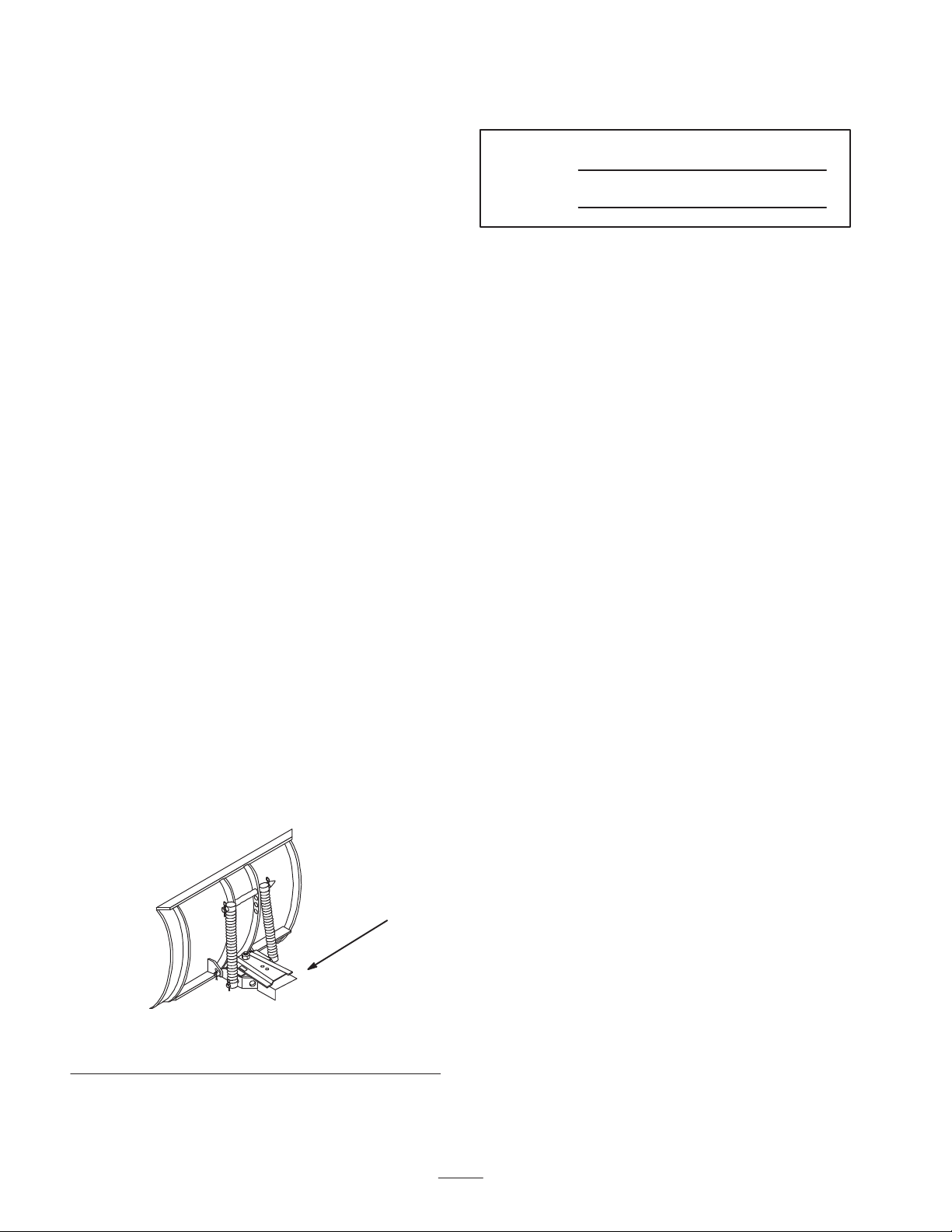
1. Lift and rotate the channel and trip spring assembly so
that the holes align with the lower blade mounts.
2. Slide the rod through the holes and secure with two 1
in. cotter pins (Fig. 2).
Note: If you have difficulty sliding the rod through the
holes, partially remove the upper rod and use a hammer to
drive the rod through. Then, install the upper rod.
3. Bend the ends of the cotter pins to secure the rod.
1
2
2
3
Assembling the lift link to the tractor lift
Page 4
4
3
2
3
1
m–3269
Figure 2
1. Channel
2. Rod
3. Cotter pin, 1/8 x 1 in.
4. Upper rod
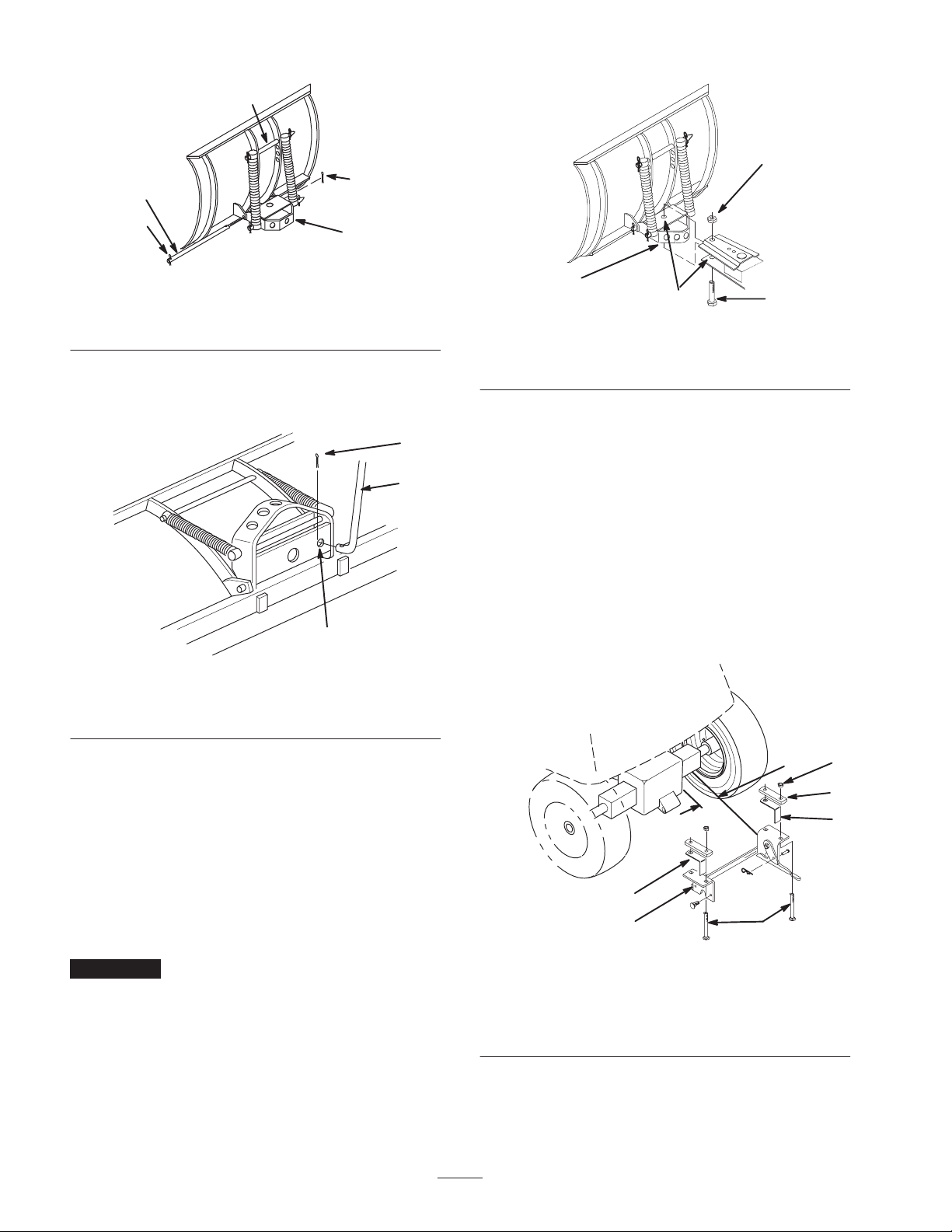
4. Insert the end of the control rod through the 1/2 in.
(13 mm) hole in the bottom plate of the channel
(Fig. 3).
1. Channel
2. Grease here
4
1
2
m–1469
3
Figure 4
3. Bolt, 3/4–16 x 3-3/4 in.
4. Locknut, 3/4 in.
3
1
2
m–3271
Figure 3
1. Control r o d
2. 1/2 in. (13 mm) hole
3. Cotter pin, 1/8 x 1 in.
5. Insert a cotter pin (1/8 x 1 in.) through the hole in the
rod and bend the ends of the pin (Fig. 3).
6. Apply general purpose grease to the pivot area of the
frame and channel.
7. Slide the channel between the frame mount and secure
it with a bolt (3/4–16 x 3-3/4 in.) and a locknut
(3/4 in.) (Fig. 4).
Note: Insert the bolt up from the underside of the frame
(Fig. 4).
Important Do not tighten the nut and bolt excessively,
thereby causing binding on the channel as it pivots from
side to side.
Mounting the Rear Hitch on the
Tractor
Center the hitch on the axle housing and secure it using 4
carriage bolts (3/8 x 3-1/2 in.) , 2 straps, and 4 locknuts
(3/8 in.) as illustrated in Figure 5.
Note: On hydrostatic models with the oil filter facing the
rear, install the hitch 3-1/4 in. (8.3 cm) from the right side
of the center housing.
Note: On 8-speed gear drive models, install angle spacers,
positioned along top and rear of axle (Fig. 5).
6
5
1. Rear hitch
2. Carriage bolt, 3/8 x
3-1/2 in.
3. Strap
1
Figure 5
2
4. Locknut, 3/8 in.
5. Angle spacer (if required)
6. 3-1/4 in. (8.3 cm) location
m–3357
4
3
5
4
Page 5

Installing Blade to Tractor
1. Remove PTO cover from the side of tractor, if so
equipped, and store it in a safe location so you can
install it when you remove the blade.
2. Install the PTO cover knobs back on the studs on the
tractor.
3. Position the blade on a level surface with space behind
it for the tractor.
11. Rotate the control handle to align the hole at the
bottom of the handle with the control rod.
1
5
6
7
4
4. Park the tractor over the blade, with the frame between
the wheels.
5. Set the parking brake, stop the engine, and remove the
key.
6. Continue sliding the frame to the rear hitch.
7. Open the latch levers and lift the frame into the rear
hitch.
8. Close the latch levers and secure them with clevis pins
(1/4 x 3/4 in.) clevis pins and small hairpin cotters
(Fig. 6).
2
1
3
4
m–2945
Figure 6
1. Frame mount
2. Latch lever
3. Clevis pin, 1/4 x 3/4 in.
4. Hairpin cotter-small
8
6
7
8
3
10
9
2
Figure 7
1. Control handle
2. Control rod
3. Large hairpin cotter
4. Release lever
5. Z-fitting
6. Bolt, 1/4 x 1 in.
7. Cable clip
8. Locknut, 1/4-20 in.
9. Bolt, 1/2-13 x 1 in.
10. Jam nut, 1/2-13 in.
12.Insert the control rod through the handle end and
secure it with a large hairpin cotter (Fig. 7).
m–5576
9. Attach the control handle to the pivot support using the
pivot bolt (1/2-13 x 1 in.). Screw the bolt into the pivot
support until the handle is snug and then back it off
slightly to let the handle pivot freely (Fig. 7).
10.Secure the bolt with a jam nut (1/2 in.) (Fig. 7).
13.Thread the balled end of the cable through the keyhole
slot in the frame up to the fitting on the cable jacket.
14.Slide the fitting through the slot and push it to the
right, ensuring there is a jam nut (1/2 in.) on each side
of the frame (Fig. 8).
5
Page 6

15.Connect the Z-fitting on the end of the cable to the
release lever (Fig. 7).
19.Pull down on the cable jacket to remove slack and
secure the cable to the handle using 3 cable clips, 3
bolts (1/4 x 1 in.), and 3 locknuts (1/4-20 in.) (Fig. 7).
1
5
7
6
2
4
Figure 8
1. Rear view
2. Front view
3. Cable jacket
4. Cable
16.Tighten the jam nuts (Fig. 8).
3
6
7
5. Fitting
6. Keyhole slot
7. Jam nuts
m05040 & 5041
20.Set the Dial-a-Height to the Mounting Position (lowest
setting), and lower the attachment lift all the way.
21.Attach the lift link between blade and tractor
attachment lift hole, using 2 clevis pins (3/8 x 7/8 in.)
and medium hairpin cotters (Fig. 10).
1
3
2
4
m–2946
Figure 10
1. Attachment lift
2. Lift link
3. Clevis pin, 3/8 x 7/8 in.
4. Hairpin cotter, mediu m
Note: To use the blade with down pressure, purchase a
long lift link kit and install it between tractor lift and
blade.
17.Insert the balled end of the cable into the cable bracket
(Fig. 9).
3
4
1
1
2
4
m–5043
Figure 9
1. Cable bracket
2. Cable
3. Angle pin
4. Cotter pin, 1-1/4 in.
(32 mm)
18.Attach the cable bracket to the angle pin at the blade
assembly (Fig. 9) with a cotter pin (1-1/4 in.).
Note: Put the cotter pin through the hole that removes the
most slack from the cable.
Removing the Blade
Note: Save all hardware, rods, washers, and hairpin
cotters for reuse when installing blade.
1. Park the machine on a level surface.
2. Raise attachment lift to the transport position.
3. Turn the Dial-a-Height knob counterclockwise, all the
way, and lower the attachment lift lever to the
mounting position.
4. Set the parking brake, stop the engine, and remove the
key.
5. Remove the two clevis pins and hairpin cotters
securing the lift link between the blade and the tractor
attachment lift (Fig. 10).
6. Open the latch levers and lower the frame from the
rear hitch.
7. Close the latch levers and secure them closed with the
clevis pins and hairpin cotters (Fig. 11).
Note: Save all hardware, rods, washers and hairpin cotters
for use when installing blade.
6
Page 7

2
1
1
2
1
3
Figure 11
1. Frame mount
2. Latch lever
8. Remove the hairpin cotter and control rod from the
control handle (Fig. 7).
9. Begin sliding the blade forward and toward the right
side of the tractor.
10.After the frame clears the right rear tire, rotate the
control handle, next to the frame.
11. Roll the tractor away from the frame.
4
3. Clevis pin
4. Hairpin cotter
m–2945
Operation
Caution
If you hit fixed objects with the blade, the tractor
could stop abruptly, causing you to lose control,
personal injury, and equipment damage.
• Travel at a safe, slow speed.
• Check the area to be plowed and mark all fixed
objects so you can avoid them.
2
Figure 12
1. Up 2. Down
2
1
Figure 13
1. Lift lever
2. Button
3. Dial-A-Height
m–2317
3
m–2514
Raising and Lowering the
Blade
Depending on your tractor model, it will have either a
power or a manual lift lever (Fig. 12 and 13) to raise and
lower attachments.
Raising the Blade Using a Power Lift
Lever
1. Turn key to the On or Run position.
2. Push the lift lever up to raise the attachment lift
(Fig. 12).
Lowering the Blade Using a Power Lift
Lever
1. Turn key to the On or Run position.
2. Push the lift lever down to lower the attachment lift
(Fig. 12).
7
Page 8

Raising the Blade Using a Manual Lift
Lever
1. Stop the machine.
2. Pull the attachment lift lever rearward until the blade
raises and the latch locks (Fig. 13).
Lowering the Blade Using a Manual Lift
Lever
1. Stop the machine.
2. Pull attachment lift lever rearward, to release lift
pressure and push the button on top to release the latch
(Fig. 13).
3. Move the lift lever forward to lower the blade (Fig.13).
Adjusting Dial-A-Height
The Dial-A-Height control (Fig. 13) is used to adjust the
downward travel of the attachment.
2. Push or pull the handle to change the angle.
3. Release the lever and pull or push the handle until the
locking pin on the blade snaps into place.
Adjusting the Blade Trip
Springs
You can mount the blade trip springs in four positions.
The top hole provides the greatest scraping pressure and
the bottom hole provides the least scraping pressure
(Fig. 15). Toro recommends using the second hole from
the top for removing snow.
1. Remove the hairpin cotter and slide the rod from the
blade and springs (Fig. 15).
2. Slide the rod through the springs and the new hole
position in the blade (Fig. 15).
1
4
1. Raise the attachment lift.
2. Rotate the Dial-a-Height knob to change the stop
location.
Turn the knob clockwise to raise and counterclockwise
to lower the height of the attachment.
Adjusting the Blade Angle
You can turn the blade from side to side, in 5 positions.
You control the angle using the control handle (Fig. 14).
1. Squeeze the release lever toward the handle (Fig. 14).
2
Figure 14
1. Handle 2. Release lever
1
m–5577
2
1. Hairpin cotter
2. Rod
Figure 15
3. Spring
4. T op hole
3
m–3395
Tips for Using the Blade
The following lists contains information that will help you
obtain the best possible results with your blade:
• Remove snow as soon as possible after it falls.
• Remove snow from a driveway by making one pass
down the center and then plowing snow to either side
on successive passes.
• If the tractor looses traction when using the snow
blade, install wheel weights and/or tire chains, which
are available from your Authorized Service Dealer.
• Install the optional skid shoe kit is to control the height
of blade from the ground for even scraping if desired.
8
Page 9

Maintenance
Recommended Maintenance Schedule
Maintenance Service
Interval
25 hours
Yearly/Storage Service
Maintenance Procedure
• Grease the channel pivot
• Oil the linkages
• Grease the channel pivot
• Oil the linkages
• Examine the scraper for wear and replace if damaged or worn
• Paint chipped surfaces (Paint is available from your Authorized Service Dealer.)
Caution
If you leave the key in the ignition switch, someone could accidently start the engine and
seriously injure you or other bystanders.
Remove the key from the ignition and disconnect the wire from the spark plug before you do
any maintenance. Set the wire aside so that it does not accidentally contact the spark plug.
Greasing and Lubrication
Grease and oil the machine after every 25 operating hours
or once a year, whichever occurs first.
Grease Type: General-purpose grease.
Oil Type: SAE 10W or l0W30.
Grease the Channel Pivot
1. Lower the attachment.
2. Set the parking brake, stop the engine, and remove the
ignition key.
3. Clean the area around the channel pivot with a rag.
Apply grease to the pivot bolt, frame and sector
(Fig. 16).
m–1473
Figure 16
4. Wipe off excess grease.
Oil Linkages
1. Set the parking brake, stop the engine, and remove the
ignition key.
2. Place a few drops of oil on all movable linkages
(Fig. 16).
3. Wipe off excess oil.
9
Page 10

Reversing the Scraper Blade
The scraper blade contacts the ground, preventing damage
to the snow blade. Periodically inspect the scraper blade
for wear. When the scraper becomes worn, before the
working surface contacts the housing, reverse the scraper
blade.
1. Start the tractor, raise the blade, and support the
housing off the ground.
2. Set the parking brake, stop the engine, and remove the
ignition key.
3. Remove the locknuts and carriage bolts securing the
scraper (Fig. 17).
4. Reverse the scraper blade to replace a worn edge and
install it with the previously removed hardware
(Fig. 17).
3
2
7. Cover the machine to protect it and keep it clean.
1
m–1468
Figure 17
1. Lock nut
2. Carriage bolt
3. Scraper blade
Storage
1. Before long-term storage, wash the machine with mild
detergent and water to remove dirt and grime from the
entire machine.
2. Check the condition of the scraper blade; refer to
Reversing the Scraper Blade, page 10.
3. Grease and oil the blade; refer to Greasing and
Lubrication, page 9.
4. Check and tighten all bolts, nuts, and screws. Repair or
replace any part that is damaged.
5. Paint all scratched or bare metal surfaces. Paint is
available from your Authorized Toro Dealer.
6. Store the machine in a clean, dry garage or storage
area.
10
Page 11

11
Page 12

 Loading...