

Page 1

FORM NO. 3318–823
Wheel
Horse
48” Snow Blade
for
Classic
Model No. 79350 – 8900001 & Up
Graden T
ractors
Operator’s Manual
IMPORTANT: Read this manual carefully. It contains information about your
safety and the safety of others. Also become familiar with the controls and
their proper use before you operate the product.
Page 2
Introduction
We want you to be completely satisfied with your
new product, so feel free to contact your local
Authorized Service Dealer for help with service,
genuine replacement parts, or other information you
may require.
Whenever you contact your Authorized Service
Dealer or the factory, always know the model and
serial numbers of your product. These numbers will
help the Service Dealer or Service Representative
provide exact information about your specific
product. You will find the model and serial number
plate located in a unique place on the product as
shown below
.
1
The warning system in this manual identifies
potential hazards and has special safety messages that
help you and others avoid personal injury, even death.
DANGER, WARNING and CAUTION are signal
words used to identify the level of hazard. However,
regardless of the hazard, be extremely careful.
DANGER signals an extreme hazard that will cause
serious injury or death if the recommended
precautions are not followed.
WARNING signals a hazard that may cause serious
injury or death if the recommended precautions are
not followed.
CAUTION signals a hazard that may cause minor or
moderate injury if the recommended precautions are
not followed.
Two other words are also used to highlight
information. “Important” calls attention to special
mechanical information and “Note” emphasizes
general information worthy of special attention.
m–1237
1. Model
For your convenience, write the product model and
serial numbers in the space below.
Model No:
Serial No.
and Serial Number Plate
The left and right side of the machine is determined
by sitting on the seat in the normal operator’s
position.
Printed in USA
The Toro Co. – 1997
Page 3

Contents
Page
Assembly 2.
Loose Parts 2
Assemble Blade3. . . . . . . . . . . . . . . . . . . . .
Mount Rear Hitch 4
Installing Blade to Tractor 4
Removing the Blade6. . . . . . . . . . . . . . . . . .
Operation 8
Adjusting Dial-A-Height 8
Attachment Lift Lever 8
. . . . . . . . . . . . . . . . . . . . . . . . . . . . .
. . . . . . . . . . . . . . . . . . . . . . . . .
. . . . . . . . . . . . . . . . . . . .
. . . . . . . . . . . . .
. . . . . . . . . . . . . . . . . . . . . . . . . . . . . .
. . . . . . . . . . . . . .
. . . . . . . . . . . . . . . .
Page
Attachment Power Lift 9
Adjusting Blade Index 9
Adjusting Blade Trip Springs 10
Tips for Using Snow Blade 10
Maintenance 11
Service Interval Chart 11
Greasing and Lubrication 12
Reversing the Scraper Blade 13
Storage 13
. . . . . . . . . . . . . . . . . . . . . . . . . . . .
. . . . . . . . . . . . . . . . . . . . . . . . . . . .
. . . . . . . . . . . . . . . .
. . . . . . . . . . . . . . . .
. . . . . . . . . .
. . . . . . . . . . . .
. . . . . . . . . . . . . . . .
. . . . . . . . . . . . . .
. . . . . . . . . . .
1
Page 4

Assembly
Loose
Parts
Note: Use the chart below to identify parts used for assembly.
DESCRIPTION QTY. USE
Blade assembly
Rod
Control rod
Cotter pin 1/8 x 1” (26 mm)
Frame assembly
Bolt 3/4–16 x 3-3/4” (95 mm)
Locknut 3/4–16
Hairpin cotter–large
Rear hitch assembly
Strap
Angle bracket (if required)
Carriage bolt 3/8–16 x 3-1/2” (89 mm)
Locknut 3/8–16
1
1
1
3
1
1
1
1
1
2
2
4
4
Assemble blade to frame
Mount rear hitch to tractor
Lift link
Clevis pin 3/8 x 7/8” (22 mm)
Hairpin cotter–medium
Operator’
Registration Card
s Manual
1
2
2
1
1
Assemble lift link to tractor lift
Read before operating
Fill out and return to T
oro
2
Page 5
Assembly
Assemble
Blade
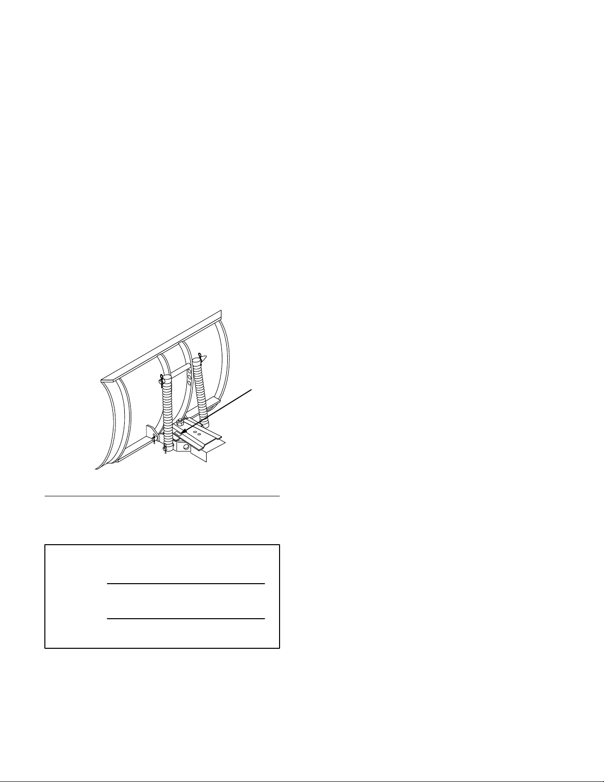
1. Lift and rotate channel and trip spring assembly
so holes align with lower blade mounts. Slide
rod through holes and secure with (2)
1/8 x 1” (26 mm) cotter pins (Fig. 1).
3
2
3
1
m–269
Figure 1
1. Channel
2. Rod
3. Cotter
(26 mm)
pin 1/8 x 1”
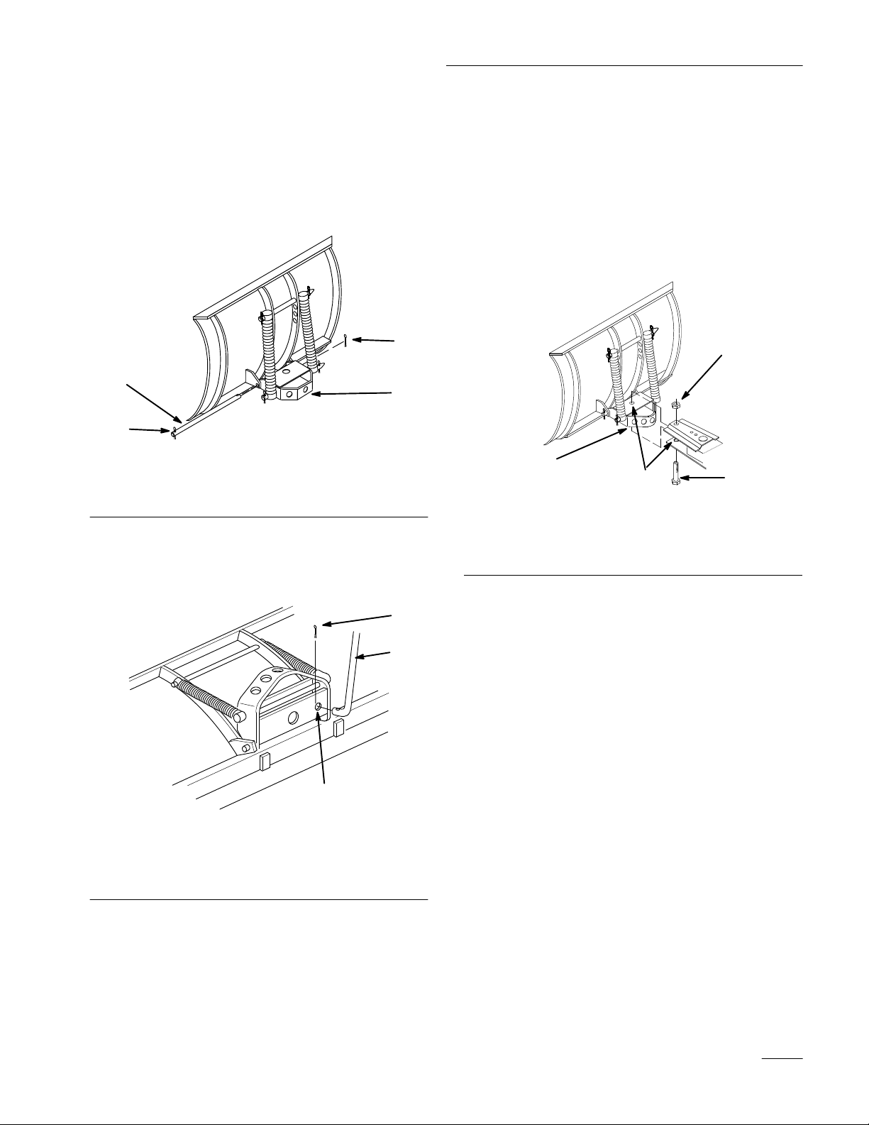
2. Insert control rod in 1/2” (13 mm) hole in
bottom plate of channel. Secure control rod with
1” (26 mm) cotter pin between plates (Fig. 2).
3. Apply general purpose grease to the pivot area of
frame and channel. Slide channel between frame
mount and secure with 3/4–16 x 3-3/4” (95 mm)
bolt, up from the bottom, and 3/4” locknut
(Fig. 3).
IMPORTANT: Do not tighten nut and bolt
excessively to cause binding on channel as it
pivots side-to-side.
4
1. Channel
2. Grease
here
1
2
Figure 3
3.
Bolt 3/4–16 x 3-3/4”
(95 mm)
4.
Locknut 3/4”
m–1469
3
1. Control
2.
rod
Channel–1/2” (13 mm)
hole
Figure 2
2
3.
Cotter pin 1” (26 mm)
3
1
m–3271
3
Page 6

Assembly
Mount
Rear Hitch
1. Center hitch on axle housing and install with (4)
3/8 x 3-1/2”( 89 mm) carriage bolts, (2) straps
and (4) 3/8–16 locknuts as shown (Fig. 4).
Note: On hydrostatic models with oil filter
facing rear locate hitch 3-1/4” (8.3 cm)
from right side of center housing.
Note: On 8-speed gear drive models install
angle spacers, positioned along top and
rear of axle.
6
Installing
Blade to T
ractor
1. Remove power take off (PTO) cover from side
of tractor, if so equipped.
2. Position blade on a level surface with space
behind for tractor.
3. Rotate lever rearward next to frame.
4. Park the tractor over blade, with frame between
wheels. Set the parking brake, and turn the
ignition key to “OFF” to stop the engine.
Remove the key.
5. Slide frame toward right rear tire and rotate
handle to vertical position. Then continue sliding
frame to rear hitch.
4
6. Open latch levers and lift frame into position at
3
5
rear hitch. Close latch levers and secure closed
with 1/4 x 3/4” (19 mm) clevis pins and small
hairpin cotters (Fig. 5).
1. Rear
2.
3. Strap
hitch
Carriage bolt 3/8 x 3-1/2”
(89 mm)
5
1
Figure 4
2
Locknut 3/8”
4.
5.
Angle spacer (if required)
6.
3-1/4” (8.3 cm) location
m–3357
3
1. Frame
2.
Latch lever
mount
Figure 5
4
3.
Clevis pin 1/4 x 3/4
(19 mm)
4.
Hairpin cotter-small
2
1
m–2945
4
Page 7

Assembly
7. With index handle vertical attach cable Z end to
back hole of triangle index plate (Fig. 6).
8. Attach control rod to index lever with large
hairpin cotter (Fig. 6).
9. Move index lever to center position and adjust
cable turnbuckle so the index pin is pulled out of
channel when the release lever is squeezed and
blade moves side-to-side when lever is pushed
and pulled (Fig. 6).
10. Tighten cable jam nut securely.
1
5
2
3
11. Set Dial-a-Height to the Mounting Position, and
lower attachment lift all the way; refer to
Adjusting Dial-A-Height.
12. Attach lift link between blade and tractor
attachment lift hole. Secure with (2) 3/8 x 7/8”
(22 mm) clevis pins and medium hairpin cotters
(Fig. 7).
1
3
1. Attachment
2.
Lift link
lift
Figure 7
2
3.
Clevis pin 3/8 x 7/8”
(22 mm)
4.
Hairpin cotter-medium
4
m–2946
1. Index
2.
3.
lever
Back hole of index plate
Control rod
4
Figure 6
4.
Hairpin cotter–large
5. T
urnbuckle and jam nut
m–2949
Note: To use blade with “Down Pressure”,
purchase long lift link kit (P\N 7706)
and install between tractor lift and
blade.
5
Page 8

Assembly
Removing
the Blade
Note: Save all hardware, rods, washers and
hairpin cotters for reuse when
installing blade.
1. Park the machine on a level surface, set the
parking brake, and turn the ignition key to
“OFF” to stop the engine. Remove the key.
2. Raise attachment lift to the transport position.
Turn the Dial-a-Height knob counterclockwise,
all the way, and lower the attachment lift lever to
the mounting position; refer to Lowering
Attachments.
3. Remove (2) clevis pins and hairpin cotters
securing lift link between blade and tractor
attachment lift (Fig. 8).
1
4. Open latch levers and lower frame from rear
hitch. Close latch levers and secure closed with
clevis pins and hairpin cotters (Fig. 9).
Note: Save all hardware, rods, washers and
hairpin cotters for reuse when
installing blade.
2
1
3
1. Frame
2.
Latch lever
Figure 9
mount
4
3.
Clevis pin
4.
Hairpin cotter
m–2945
3
1. Attachment
2.
Lift link
lift
Figure 8
2
3.
Clevis pin
4.
Hairpin cotter
4
m–2946
6
Page 9

5. Remove hairpin cotter and control rod from
index lever (Fig. 10).
6. Begin sliding blade forward and toward right
side of tractor. After frame clears right rear tire,
rotate index lever back, next to frame.
7. Roll tractor away from above frame.
1
2
Assembly
1. Index
2.
Control rod
lever
3
Figure 10
3.
m–2949
Hairpin cotter–large
7
Page 10

Operation
POTENTIAL
HAZARD
• Hitting fixed objects can cause the tractor
to stop abruptly.
WHAT CAN HAPPEN
• Stopping abruptly can cause loss of control,
equipment damage and personal injury.
HOW TO AV
OID THE HAZARD
• Travel at a safe, slow speed.
• Check area to be plowed and mark all fixed
objects so they can be avoided.
Adjusting
The Dial-A-Height control (Fig. 11) is used to limit
the downward travel of the attachment. The
Dial-A-Height knob is rotated to change the location
of this stop, up or down.
Dial-A-Height
Attachment
The attachment lift lever (Fig. 11) is used to raise and
lower various attachments.
Lift Lever
Raising Attachments
1. Pull attachment lift lever rearward until latch
locks. In this position the lift will hold the
attachment in the up, or raised position.
Lowering Attachments
1. Pull attachment lift lever rearward, to release lift
pressure, and push the button on top to release
the latch. Move lift lever forward to lower
attachment.
2
1
1. Raise the attachment lift lever: Refer to Raising
Attachments. In the raised position the
Dial-A-Height knob (Fig. 11) can be rotated to
change the stop location. Turn clockwise to raise
and counterclockwise to lower the height of the
attachment.
1. Lift
lever
2. Button
Figure 1
3
m–2514
1
3. Dial-A-Height
8
Page 11

Operation
Attachment
Power Lift
The attachment power lift (Fig. 12) is used to raise
and lower attachments.
Raising Attachments
1. Start the engine, refer to; Starting and Stopping
the Engine; in tractor Operator’
s Manual.
2. Pull the lift lever in the “UP” direction to raise
the attachment lift (Fig. 12). This will lift and
hold the attachment in the up, or raised position.
Lowering Attachments
1. Start the engine, refer to; Starting and Stopping
the Engine; in tractor Operator’
2. Push the lift lever in the “DOWN” direction to
lower the attachment lift (Fig. 12). This will
lower the attachment lift.
s Manual.
Adjusting
Blade Index
The blade can be indexed side to side, in 5 positions.
The direction is controlled by the handle on the right
side (Fig. 13).
1. Squeeze the release lever toward the handle
(Fig. 13).
2. Push or pull lever to change index position and
release lever. Index pin must snap into hole in
channel to retain position.
2
1
m–3358
2
1
1
2
Figure 12
1. UP 2. DOWN
m–2317
Figure 13
1. Handle 2. Release
lever
9
Page 12

Operation
Adjusting
Blade T
rip Springs
The blade trip springs can be mounted in 4 positions.
The top hole provides greatest scraping pressure and
the lower hole least scraping pressure (Fig. 14).
1. Remove hairpin cotter and slide rod out from
blade and springs (Fig. 14).
2. Slide rod through springs and new hole position
in blade (Fig. 14).
4
2
1
3
1237
Tips
for Using Snow Blade
Remove snow as soon as possible after it falls. This
produces best snow removal results.
Snow is generally removed from driveway by making
one pass down the center and then plowing snow to
either side on successive passes.
If tractor looses traction when using snow blade,
wheel weights and tire chains may be available from
your dealer.
Blade trip springs can be adjusted for scraping
aggressiveness and surface conditions. Second hole
from the top is recommended for snow. Refer to
adjusting blade trip springs.
1. Hairpin
2. Rod
cotter
Figure 14
3. Spring
4. T
op hole
10
Page 13

Maintenance
Service
Service
Grease–Channel pivot
Oil–Linkages X X X
Chipped Surfaces–paint
Scraper–check for wear
Interval Chart
Operation
POTENTIAL HAZARD
Each
Use5Hours25Hours
X X X
Storage
Service
X
X X
• If you leave the key in the ignition switch, someone could start the engine.
WHAT CAN HAPPEN
• Accidental starting of the engine could seriously injure you or other bystanders.
HOW TO AV
OID THE HAZARD
• Remove the key from the ignition switch and pull the wire off the spark plug before
you do any maintenance. Also push the wire aside so it does not accidentally contact
the spark plug.
Fall
Service
Notes
11
Page 14

Maintenance
Greasing
and Lubrication
Service Interval/Specification
Grease and oil the blade after every 25 operating
hours or once a year, whichever occurs first.
Grease Type: General-purpose grease.
Oil Type: SAE 10W or 10W30.
Grease Channel Pivot
1. Disengage the power take off (PTO), set the
parking brake, and turn the ignition key to
“OFF” to stop the engine. Remove the key.
2. Clean the area around channel pivot with a rag.
Apply grease to pivot bolt, frame and sector
(Fig. 15).
3. Wipe of
f excess grease.
Oil Linkages
1. Disengage the power take off (PTO), set the
parking brake, and turn the ignition key to
“OFF” to stop the engine. Remove the key.
2. Place a few drops of oil on all movable linkages
(Fig. 15).
3. Wipe off excess oil.
1473
Figure 15
12
Page 15

Maintenance
Reversing
the Scraper Blade
The scraper blade contacts the ground preventing
damage to the snow blade. Periodically inspect the
scraper blade for wear. When scraper becomes worn,
before working surface contacts the housing, reverse
the scraper blade.
1. Disengage the power take off (PTO), set the
parking brake, and turn the ignition key to
“OFF” to stop the engine. Remove the key.
2. Raise the attachment lift lever: Refer to Raising
Attachments, and support the housing off the
ground.
3. Remove lock nuts and carriage bolts to remove
scraper blade (Fig. 16).
4. Reverse scraper blade to replace a worn edge and
install with previously removed hardware
(Fig. 16).
Storage
1. Before long term storage wash the blade with
mild detergent and water to remove dirt and
grime from the entire attachment.
2. Check the condition of the scraper blade; refer to
Reversing Scraper Blade, page 13.
3. Grease and oil the blade; refer to Greasing and
Lubrication, page 12.
4. Check and tighten all bolts, nuts, and screws.
Repair or replace any part that is damaged or
defective.
5. Paint all scratched or bare metal surfaces. Paint
is available from your Authorized Service
Dealer.
6. Store the blade in a clean, dry garage or storage
area. Cover the machine to protect it and keep it
clean.
1. Lock
2.
Carriage bolt
2
nut
3
1
Figure 16
3.
Scraper blade
1468
13
Page 16

 Loading...