


FormNo.3449-890RevA
E-ZVac™CompleteTwinBagger
79345
KomplettesHeckfangsystemmitzweiFangkörben
E-ZVac™
79345
SystèmederamassagecompletE-ZVac™HDàdeux
bacs
79345
E-ZVac™volledigedubbelegrasvanger
79345
www.T oro.com.
*3449-890*


FormNo.3414-381RevB
E-ZVac
TimeCutter
ModelNo.79345—SerialNo.400000000andUp
™
CompleteTwinBagger
®
HDRidingMower
Registeratwww.T oro.com.
OriginalInstructions(EN)
*3414-381*B

WARNING
CALIFORNIA
Proposition65Warning
Useofthisproductmaycauseexposure
tochemicalsknowntotheStateof
Californiatocausecancer,birthdefects,
orotherreproductiveharm.
Introduction
Readthisinformationcarefullytolearnhowtooperate
andmaintainyourproductproperlyandtoavoid
injuryandproductdamage.Y ouareresponsiblefor
operatingtheproductproperlyandsafely .
Visitwww.Toro.comforproductsafetyandoperation
trainingmaterials,accessoryinformation,helpnding
adealer,ortoregisteryourproduct.
Wheneveryouneedservice,genuineToroparts,or
additionalinformation,contactanAuthorizedService
DealerorToroCustomerServiceandhavethemodel
andserialnumbersofyourproductready.Figure1
identiesthelocationofthemodelandserialnumbers
ontheproduct.Writethenumbersinthespace
provided.
Figure1
1.Modelandserialnumberlocation
ModelNo.
SerialNo.
Thismanualidentiespotentialhazardsandhas
safetymessagesidentiedbythesafety-alertsymbol
(Figure2),whichsignalsahazardthatmaycause
seriousinjuryordeathifyoudonotfollowthe
recommendedprecautions.
g000502
Figure2
1.Safety-alertsymbol
Thismanualuses2wordstohighlightinformation.
Importantcallsattentiontospecialmechanical
informationandNoteemphasizesgeneralinformation
worthyofspecialattention.
Contents
Safety.......................................................................3
TowingSafety.....................................................3
SafetyandInstructionalDecals..........................4
Setup........................................................................5
1PreparingtheMachine.....................................6
2InstallingtheWeight.........................................6
3RemovingtheGrassDeectorandBelt
Cover..............................................................7
4InstallingtheBafeandBlower
Support...........................................................8
5InstallingthePulleyAssembly ,BeltCover,
andShoulderBolt..........................................10
6InstallingtheAttachmentMount.....................10
7InstallingtheLatchRod..................................12
8AssemblingtheBaggerTop...........................13
9InstallingtheBaggerT op................................14
10InstallingtheBlowerAssembly.....................14
11InstallingtheBlowerBeltandPowered
BaggerCover................................................16
12InstallingtheDischargeTubes.....................17
Operation................................................................19
EmptyingtheGrassBags.................................19
ClearingObstructionsfromtheBagger
System..........................................................20
RemovingtheBagger.......................................20
g005673
OperatingTips.................................................21
Maintenance...........................................................22
RecommendedMaintenanceSchedule(s)...........22
PreparingforMaintenance...............................22
CleaningtheHoodScreen................................22
CleaningtheBaggerandBags.........................23
InspectingtheBlowerBelt................................23
ReplacingtheBlowerBelt.................................23
InspectingtheBagger.......................................24
InspectingtheMowerBlades............................24
Storage...................................................................24
StoringtheBaggerAttachment.........................24
Troubleshooting......................................................25
©2019—TheToro®Company
8111LyndaleAvenueSouth
Bloomington,MN55420
Contactusatwww.Toro.com.
2
PrintedintheUSA
AllRightsReserved

Safety
rear.Useextracarewhenoperatingthemachine
inreverse.
•Thegrasscatchercanobstructtheviewtothe
WARNING
Whenthebaggerisinoperation,theblower
isrotatingandcancutofforinjurehandsand
ngers.
•Beforeadjusting,cleaning,repairing,
andinspectingtheblower,andbefore
uncloggingthechute,shutofftheengine
andwaitforallmovingpartstostop.
Removethekey.
•Useastick,notyourhands,toremovean
obstructionfromtheblowerandtube.
•Keephandsandfeetawayfrommoving
parts.Donotmakeadjustmentswiththe
enginerunning.
WARNING
Debris,suchasleaves,grass,orbrushcan
catchre.Areintheengineareacancause
personalinjuryandpropertydamage.
•Keeptheengineandmuferareafreeof
debrisaccumulation.
•Usecarewhenloadingorunloadingthemachine
intoatruckortrailer.
•Donotusethemowerdeckwithoutthedischarge
deectororgrasscatcher.
•Parkthemachineonalevelsurface,disengage
thedrives,engagetheparkingbrake,andshutoff
theenginebeforeleavingtheoperator'sposition
foranyreasonincludinguncloggingoremptying
thegrasscatcher.
•Ifyouremovethegrasscatcher,installany
dischargedeectororguardthatwasremoved
toinstallthegrasscatcher.Donotoperatethe
machinewithouteithertheentiregrasscatcheror
thegrassdeectorinplace.
•Donotleavegrassinthegrasscatcherfor
extendedperiodsoftime.
•Grasscatchercomponentsaresubjecttowear,
damage,anddeterioration,whichcouldexpose
movingpartsorallowobjectstobethrown.
Frequentlycheckcomponentsandreplacethem
withmanufacturer'srecommendedpartswhen
necessary.
•Takecarewhenopeningthebaggercover
tokeepdebrisfromfallingontotheengine
andmuferarea.
•Allowthemachinetocoolbeforestoringit.
Thefollowinglistcontainssafetyinformationspecic
toToroproductsandothersafetyinformationyou
mustknow.
•Becomefamiliarwiththesafeoperationofthe
equipment,withtheoperatorcontrols,andsafety
signs.
•Useextracarewithgrasscatchersorother
attachments.Thesecanchangetheoperating
characteristicsandthestabilityofthemachine.
•Followtherecommendationsforaddingor
removingweightsasdescribedintheOperator’s
Manualforthemachine.
•Donotuseagrasscatcheronsteepslopes.A
heavygrasscatchercouldcauselossofcontrol
oroverturnthemachine.
•Slowdownanduseextracareonhillsides.Mow
slopessidetoside.Turfconditionscanaffectthe
stabilityofthemachine.Useextremecaution
whileoperatingneardrop-offs.
•Keepallmovementonslopesslowandgradual.
Donotmakesuddenchangesinspeed,directions,
orturning.
TowingSafety
•Donotattachtowedequipmentexceptatthehitch
point.
•Followtheattachmentmanufacturer's
recommendationforweightlimitsfortowed
equipmentandtowingonslopes.
•Neverallowchildrenorothersinorontowed
equipment.
•Onslopes,theweightofthetowedequipmentmay
causelossoftractionandlossofcontrol.Reduce
towedweightandslowdown.
•Stoppingdistanceincreaseswiththeweightofthe
towedload.Travelslowlyandallowextradistance
tostop.
•Makewideturnstokeeptheattachmentclearof
themachine.
•Donottowaloadthatweighsmorethanthe
towingmachine.
3

SafetyandInstructionalDecals
Safetydecalsandinstructionsareeasilyvisibletotheoperatorandarelocatednearanyarea
ofpotentialdanger.Replaceanydecalthatisdamagedormissing.
decal136-4164
136-4164
1.Warning—readtheOperator’sManual.4.Cutting/dismembermenthazard,impeller—keepawayfrom
2.Warning—hearingprotectionmustbeworn.
3.Thrownobjecthazard—donotoperatetheblowerwithoutthe
entiresysteminstalledandlatched.
movingparts;keepallguardsandcoversinplace.
5.Cutting/dismembermenthazard,impeller—disengagethe
PTO,removethekey,andwaitforallmovingpartstostop.
6.Warning;lossoftraction—donotoperatewithonly
counterbalanceweightsinstalled;donotoperatewithonly
E-ZV acinstalled;operateonlywithbothE-ZVacand
counterbalanceweightsinstalled.
109-6809
1.Crushinghazardofhand—Donotremovethewholebaggerfromthemachine.Step1:Openthebaggertop.Step2:Removethe
bag(s)fromthebagger.Step3:Donotremovethebaggertopwhenitisclosed;openthebaggertopandthenremoveit.
decal133-8061
133-8061
decal109-6809
4

Setup
LooseParts
Usethechartbelowtoverifythatallpartshavebeenshipped.
ProcedureDescription
1
2
3
4
5
6
7
8
Nopartsrequired
Weighttray1
Leftweight-traymount
Rightweight-traymount1
Suitcaseweight—16kg(35lb)
Retainingrod1
Bolt(3/8x1-1/4inches)
Flangenut(3/8inch)
Carriagebolt(3/8x1inch)
Self-tappingbolt(5/16x3/4inch)
Nopartsrequired
Blowersupport1
Hexwasher-headscrew(3/8x3/4inch)
Bafe
Carriagebolt(5/16x3/4inch)
Flangenut(5/16inch)
Pulleyassembly1
Beltcover1
Stabilizerbracket
Carriagebolt(5/16x3/4inch)
Locknut(5/16inch)
Self-tappingscrew(5/16x3/4inch)
Bolt(5/16x1inch)
Pivotframe
Hairpincotter2
Rod2
Washer2
Latchrod1
Hairpincotter1
Baggertop1
Baggerscreen1
Hairpincotter2
Qty.
Use
–
1
1
2
4
2
2
–
2
1
4
4
1
2
4
2
2
1
Preparethemachine.
Installtheweight.
Removethegrassdeectorandbelt
cover.
Installthebafeandblowersupport.
Installthepulleyassemblyandbelt
cover.
Installtheattachmentmount.
Installthelatchrod.
Assemblethebaggertop.
9
10
11
12
GrassBag
Blowerassembly1Installtheblowerassembly .
Poweredbaggercover1
Blowerbelt1
Uppertube1
Screw(1/4x3/4inches)
Washer(1/4inch)
Locknut(1/4inch)
Lowertube1
5
2Installthebaggertop.
Installtheblowerbeltandpowered
baggercover.
2
2
2
Installthedischargetubes.

Determinetheleftandrightsidesofthemachinefromthenormaloperatingposition.
1
PreparingtheMachine
NoPartsRequired
Procedure
Performthefollowingproceduretopreparethe
machineforattachingtheblowerandnishingkit.
1.Parkthemachineonalevelsurface.
2.Disengagetheblade-controlswitch,engage
theparkingbrake,andmovethemotion-control
leversoutwardtotheNEUTRAL-LOCKposition.
3.Shutofftheengineandremovethekey.
4.Ensurethatthemachineissecurefrom
movementbeforeyoubegintoworkonit.
5.Repairallbentordamagedareasofmachine
deckandreplaceanymissingparts.
6.Cleanthemachineofanydebrisonthemachine
deckorrearpartofthemachinetoease
installation.
2
InstallingtheWeight
Partsneededforthisprocedure:
1Weighttray
1
Leftweight-traymount
1Rightweight-traymount
1
Suitcaseweight—16kg(35lb)
1Retainingrod
2
Bolt(3/8x1-1/4inches)
4
Flangenut(3/8inch)
2
Carriagebolt(3/8x1inch)
2
Self-tappingbolt(5/16x3/4inch)
Procedure
CAUTION
Thebaggerchangestheweightdistributionof
themachine.Operatingthemachinewithout
thefrontweightsmaycauseanunstable
condition,whichcouldresultinalossof
control.
Ensurethefrontweightsareproperlyinstalled
beforeoperatingthemachinewiththebagger
attachment.
1.Removetheexistingboltandnutfromtheleft
andrightsideoftheplatformwhereyouwill
installtheweight-traymounts.
2.Usethe2self-tappingbolts(5/16x3/4inch),2
bolts(3/8x1-1/4inches),andangenuts(3/8
inch)tosecuretheleftandrightweight-tray
mountstothemachine(Figure3).
6

Figure3
Cutawayview
g196533
g196560
Figure5
1.Weight-traymounts
2.Bolt(3/8x1-1/4inches)4.Self-tappingbolt(5/16x
3.Usethe2carriagebolts(3/8x1inch)andange
nutstosecuretheweighttraytothemounts
(Figure4).
3.Flangenut(3/8inch)
3/4inch)
1.Retainingrod
2.Weighttray
5.Inserttheretainingrodintothetrayandrotateit
intothelockedposition(Figure5).
3.Suitcaseweight
Important:Removethesuitcaseweightwhenever
youremovethebaggerattachment.
3
RemovingtheGrass
DeectorandBeltCover
NoPartsRequired
Procedure
WARNING
Figure4
1.Carriagebolt(3/8x1inch)
2.Weight-traymount
4.Insertthesuitcaseweightintotheweighttray
withthegroovesidefacingtowardthefrontof
themachine(Figure5).
3.Weighttray
4.Flangenut(3/8inch)
Anuncovereddischargeopeningcould
allowthelawnmowertothrowobjectsinthe
operator’sorbystander’sdirectionandresult
inseriousinjury.Also,contactwiththeblade
couldoccur.
Neveroperatethelawnmowerunlessyou
g196549
installamulchplate,dischargedeector,or
grass-collectionsystem.
Inspectthegrassdeectorfordamagebeforeeach
use.Replaceanydamagedpartsbeforeuse.
1.Disengagethespringfromthenotchinthe
deectorbracketandremovethecotterpin(CE
modelsonly),slidetherodoutofthewelded
deckbrackets,spring,anddischargedeector
(Figure6).
7

Figure6
1.Rod
2.Cotterpin(CEmodels
only)
3.Deector6.Springinstalledoverthe
4.Spring
5.Deckbrackets
rod
4
InstallingtheBafeand
BlowerSupport
Partsneededforthisprocedure:
1Blowersupport
2
Hexwasher-headscrew(3/8x3/4inch)
1
Bafe
4
Carriagebolt(5/16x3/4inch)
4
Flangenut(5/16inch)
Procedure
g190642
1.Installtheblowersupporttothemowerdeck
using2hexwasher-headscrews(3/8x3/4inch)
asshowninFigure8.
2.Removethedeector(Figure6).
3.Removethe4screws(1/4x1/2inch)securing
therightbeltcover,andremovethebeltcover
(Figure7).
Note:Retainthe4screws(1/4x1/2inch)for
installationinProcedure5InstallingthePulley
Assembly,BeltCover,andShoulderBolt(page
10).
Figure7
1.Screw(1/4x1/2inch)
2.Beltcover
g201299
Figure8
1.Hexwasher-headscrew
(3/8x3/4inch)
g200974
2.Blowersupport
8

2.Removetheexistingboltandnutfromthe
mowerdeck(Figure9).
Important:For48-inchand60-inchmower
decks,thereisonlyoneboltandnutthatyou
canremove.
For54-inchmowerdeck,removetheboltand
nutasshowninFigure9.
g206496
Figure10
54-inchmowerdeckshown
Figure9
1.Existingbolt2.Existingnut
3.Installtheleftsideofthebafeusingacarriage
bolt(5/16x3/4inch)andangenut(5/16inch)
asshowninFigure10.
4.Loosenthe2carriagebolts(5/16x3/4inch)in
thebafeslots,andslidethebafeuntilthehole
alignswiththeholeinthemowerdeck(Figure
10).
1.Innerbafe
2.Holefor48-inchand
60-inchmowerdeck
installation.
3.Holefor54-inchmower
deckinstallation.
4.Rightblade9.Installthiscarriagebolt
g206498
5.Outerbafe
6.Installthiscarriagebolt
(5/16x3/4inch)and
angenut(5/16inch)after
slidingthebafe.
7.Slotsinthebafe
8.Loosenthese2carriage
bolts(5/16x3/4inch)and
2angenut(5/16inch).
(5/16x3/4inch)and
angenut(5/16inch)rst.
5.InstallbafeasshowninFigure10.
Important:Ensurethatyouusethecorrect
holeforthebafe;refertoFigure10.
6.Tightenthe2carriagebolts(5/16x3/4inch)in
thebafeslots(Figure10).
9

5
InstallingthePulley
Assembly,BeltCover,
andShoulderBolt
Partsneededforthisprocedure:
1Pulleyassembly
1Beltcover
4.Installthenewbeltcoveroverthepulley
assemblyusingthe4previouslyremoved
screws(1/4x1/2inch)asshowninFigure12.
Procedure
1.Removethenutandwasherfromtheright
mowerdeckpulley.
2.Installthepulleyassemblytotherightmower
deckpulleywiththepreviouslyremovednutand
washer(Figure11).
Important:For48-inchmowerdecks,use
thesmallblowerpulley .
For54-inchand60-inchmowerdecks,use
thelargeblowerpulley.
3.Torquethenutto136to149N∙m(100to110
ft-lb).
1.Beltcover
6
InstallingtheAttachment
Mount
Partsneededforthisprocedure:
1
Stabilizerbracket
2
Carriagebolt(5/16x3/4inch)
4
Locknut(5/16inch)
2
Self-tappingscrew(5/16x3/4inch)
2
Bolt(5/16x1inch)
1
Pivotframe
2Hairpincotter
2Rod
2Washer
g201435
Figure12
2.Screw(1/4x1/2inch)
1.Existingpulleynut
2.Existingwasher
3.Blowerpulley
Figure11
54-inchmowerdeckshown
4.Existingdeck(spindle)
pulley
5.Spindle
g201880
Procedure
1.Removetheexisting2bolts,2nuts,andhitch
bracketfromthebottomoftheengineguard
(Figure13).
10

Figure13
1.Nut3.Bolt
2.Existinghitchbracket
g201215
1.Machineframe4.Bolt(5/16x1inch)
2.Locknut(5/16inch)5.Pivotframe
3.Hole
Figure15
g201214
2.Installthestabilizerbrackettotheengineguard
using2carriagebolts(5/16x3/4inch)and2
locknuts(5/16inch)asshowninFigure14.
Figure14
1.Stabilizerbracket3.Locknut(5/16inch)
2.Carriagebolt(5/16x3/4
inch)
5.Positionthepivotframeupward,andsecurethe
pivotframetothebottomofthemachineframe
using2self-tappingscrews(5/16x3/4inch)as
showninFigure16.
g030494
g028174
Figure16
3.Removetheexisting2self-tappingscrewsfrom
thebottomofthemachineframe(Figure16).
4.Looselyinstallthepivotframetothemachine
frameusing2bolts(5/16x1inch)and2locknuts
(5/16inch)asshowninFigure15.
1.Self-tappingscrew(5/16x
3/4inch)
2.Pivotframe
6.Tightenthe2bolts(5/16x1inch)and2locknuts
(5/16inch)asshowninFigure15.
7.Installthebent,aredendofarodintothekeyed
slotintheleftsideofthemachineframe,and
movetherodrearwardtoseatitintheframe
(Figure17).
Note:Repeatthisstepfortherightsideofthe
machine.
11
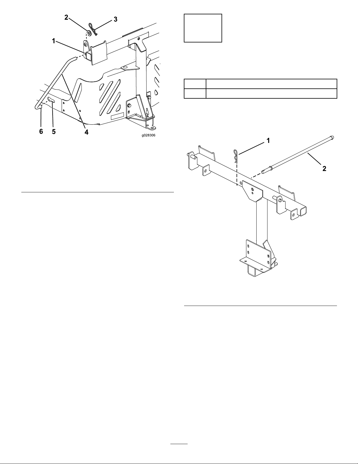
Figure17
Leftsideshown
1.Pivotframehole4.Supportrod
2.Washer
3.Hairpincotter
8.Insertthebentendsoftherodsintothe
attachmentmountasshowninFigure17and
securetheendofeachrodwithawasherand
hairpincotter.
5.Keyedslot(existing)
6.Bent,aredendoftherod
7
InstallingtheLatchRod
Partsneededforthisprocedure:
1Latchrod
1Hairpincotter
Procedure
Installthelatchrodwithahairpincotter(Figure18).
g028306
Figure18
1.Hairpincotter2.Latchrod
g201213
12

8
AssemblingtheBaggerTop
Partsneededforthisprocedure:
1Baggertop
1Baggerscreen
2Hairpincotter
Procedure
1.Turnthebaggertopover.
2.InstallthescreenasshowninFigure19and
ensurethatitslopesdowntowardthecollection
bags.
Note:Makesurethatthescreenssnapinto
placeandthetabsengagethebaggertop.
13
1.Baggertop
2.Screen
3.Screentab
g201881
Figure19
4.Slotinbaggertop
5.Hairpincotter

9
InstallingtheBaggerTop
Partsneededforthisprocedure:
2
GrassBag
Procedure
1.Installthebaggertoptothebaggerframe.
2.Slidethebracketsoverthepostsinthebagger
frameandinstallthecircularcotterpinintothe
holeintherighthandpost(Figure20).
3.Rotatethebaggerhooddowntotheoperating
position.
4.Liftthebaggertopandinstallthebagsbysliding
thebagframehooksontotheretainingbrackets
(Figure21).
Note:T oremovethecircularcotterpin,
continuetorotateitinthesamedirectionas
installed.
g033032
Figure21
1.Bag3.Retainingbracket
2.Baggerframe4.Bagframehook
5.Lowerthebaggertopontothebags(Figure22).
g033030
Figure22
1.Baggerhood
2.Baggerframe
3.Bracket,baggerhood
6.Securethehoodwiththelatch(Figure22).
g016265
Figure20
4.Circularcotterpin
5.Post
14

10
InstallingtheBlower
Assembly
Partsneededforthisprocedure:
1Blowerassembly
Procedure
WARNING
Anuncovereddischargeopeningallowsthe
lawnmowertothrowobjectstowardyouor
bystanders,resultinginseriousinjury.Also,
contactwiththebladecouldoccur.
•Neveroperatethelawnmowerwithouta
coverplate,amulchplate,oragrasschute
andcatcher.
•Makesurethatthegrassdeectoris
installedwhenyouremovethegrasschute
andcatcher.
Important:Installtheside-dischargechutewhen
youremovethebaggerandblower.
Important:Saveallthehardwareandthe
side-dischargechute.
1.Ifnecessary,installthebeltontotheblower
pulley(Figure25).
g201514
Figure23
1.Blowerassembly3.Blowersupport
2.Blowerpivotpin
g201893
Figure24
1.Blowerlatch
2.Inserttheblowerpivotpinintotheblower
supportandrotatetheblowerassemblyinward
towardthemachine(Figure23).
Note:Theblowerassemblyshould
automaticallylatchasshowninFigure24.
15

11
InstallingtheBlowerBelt
andPoweredBaggerCover
Partsneededforthisprocedure:
1Poweredbaggercover
1Blowerbelt
Procedure
1.Installthebeltaroundtheblowerpulley(Figure
25andFigure26);referto10Installingthe
BlowerAssembly(page14).
Usethefollowingbeltbasedonthemower
decksize:
48-inchMower
Deck
ToroPartNo.
127-0074
54-inchMower
Deck
ToroPartNo.
127-0075
60-inchMower
ToroPartNo.
127-0076
g201513
Figure26
1.Blowerpulley5.Idlerarm
2.Blowerinposition(housing
portionremovedfor
illustrativepurposes)
Deck
3.Spring7.Idler/tensionpulley
4.Idler-pulleypost8.Blowerbelt
6.Drivepulley
Figure25
BlowerBeltRouting
1.Idler/tensionpulley
2.Blowerpulley4.Drivepulley
3.Blowerbelt
2.Ensurethatthebeltremainsalignedtothe
blowerpulleywhileyouareinstallingtheblower
assembly.
3.Pullthespringloadedidlerpulleyawayfromthe
xedspringpost,androutethebeltaroundthe
mowerdeckpulley(Figure26).
Note:Ensurethatthebeltisroutedaroundthe
blowerpulleycorrectly.
4.Routethebeltaroundthedrivepulleyas
illustratedinFigure25andFigure26.
5.Installthepoweredbaggercoveroverthebelt
cover,andsecureitbytighteningtheknob
g201516
(Figure27).
16

Figure27
1.Knob3.Beltcover
2.Poweredbaggercover
12
InstallingtheDischarge
g201515
Tubes
Partsneededforthisprocedure:
1Uppertube
2
Screw(1/4x3/4inches)
2
Washer(1/4inch)
2
Locknut(1/4inch)
1Lowertube
Procedure
Important:Makesurethatthemowerdeckisin
thelowestheight-of-cutpositionbeforeinstalling
thedischargetubes.
Note:Remembertoinstallthegrassdeectorwhen
youremovethebaggerfromthemower.
1.DisengagethePTOandengagetheparking
brake.
2.Shutofftheengineandremovethekey.
3.Lowerthemowerdecktothelowestheight-of-cut
position.
4.Removethebagsforviewingthetubeunder
thehood.
5.Lowerandlatchthehood.
6.Usebothlatchestoattachthelowertubetothe
blowerassembly(Figure28).
g018444
Figure28
LowerDischargeTubeLatch
1.Blowerassembly3.Latch
2.Upperlatch
7.Makenoteofwherethe2boltsintheuppertube
areinstalled.
Note:Theholenearthemoldedarrowheads
willnotbeused.
8.Removethe2boltsinthelowerendoftheupper
tube.
9.Usethe2holesasatemplateforthelowertube.
Note:Retainthehardware.
10.Inserttheupperend(noholes)oftheuppertube
throughthetubesealinthehoodbypushing
thetubeinuntilthetubecontactstheinsideof
thehood.
11.Pulltheuppertubeoutslightlysothattheseal
extendsoutwardandoverthelowertube(Figure
29).
Note:Ensurethenotchinthelowertubeisat
thebottomwheninstalled(Figure30).
17

Figure29
1.Uppertube3.Baggerhood
2.Rubbersealprotrudingout
12.Aligntheuppertubeholestomatchthedimples
onthesurfaceofthelowertube.
Note:Ensurethatthesideproleappearsas
showninFigure30.
Note:Donotusetheopenholenearthe
moldedarrowheads.
g018440
g018439
Figure31
DrillingLowerDischargeTube
Figure30
1.Uppertube
2.Existinghole(bolt
removed)
3.Notchatthebottomofthe
tubewheninstalled
4.Lowertube
13.Usingtheexistingholesintheuppertubeas
atemplate,drill2holes,6.5mm(1/4inch)
diameter,throughthedimplesonthelowertube
(Figure31).
1.Dimples4.Uppertube
2.Lowertube
g020776
3.Drill6.5mm(1/4inch)
diameterhole
5.Installscrew(1/4x3/4
inch),washer(1/4inch),
andlocknut(1/4inch)
here.
6.Uppertube—existing
holes
14.Removetheupperandlowertubesfromthe
machine.
15.Slidethetubestogetherandaligntheholes.
16.Installthewashers(1/4inch)ontothebolts
(Figure31).
17.Usingahexkeytool,installthescrews(1/4x
3/4inch)andwashers(1/4inch)fromtheinside
ofthelowertubeandthroughtheexistingholes
intheuppertube(Figure31).
18

18.Securethetubestogetherwiththenuts(1/4
inch)asshowninFigure31.
Operation
19.Inserttheupperdischargetubethroughthetube
sealinthehood.
20.Pulltheuppertubeoutslightlysothattheseal
extendsoutwardandovertheblowerassembly
(Figure29).
21.Usebothlatchestoattachthelowertubetothe
blowerassembly(Figure28).
Note:Determinetheleftandrightsidesofthe
machinefromthenormaloperatingposition.
WARNING
Toavoidpersonalinjury ,followthese
procedures:
•Becomefamiliarwithalloperatingand
safetyinstructionsintheOperator's
Manualforthemowerbeforeusingthis
attachment.
•Neverremovethedischargetube,bags,
baggerhood,orthechutewhiletheengine
isrunning.
•Alwaysshuttheengineoffandwaitforall
movingpartstostopbeforeclearingan
obstructionfromthebaggingsystem.
•Neverperformmaintenanceorrepairs
whiletheengineisrunning.
EmptyingtheGrassBags
Becarefulwhenliftingorhandlingagrassbagthatis
full.T oemptythegrassbags:
1.Parkthemachineonalevelsurface.
2.Disengagetheblade-controlswitch,engage
theparkingbrake,andmovethemotion-control
leversoutwardtotheNEUTRAL-LOCKposition.
3.Shutofftheengineandremovethekey.
4.Raisethebaggerhood(Figure32).
Figure32
g005758
5.Compressthedebrisintothebags.
6.Withbothhands,liftuponthebagandunhookit
fromtheretainingbracket,emptythebag.
7.Repeattheprocedurefortheotherbag.
8.Installthebagsbyslidingthebagframehooks
ontotheretainingbrackets(Figure33).
19

2.Disengagetheblade-controlswitch,engage
theparkingbrake,andmovethemotion-control
leversoutwardtotheNEUTRAL-LOCKposition.
3.Shutofftheengineandremovethekey.
4.Emptythebags.
5.Unlatchthelowertube.
6.Removethetubesfromthebagger.
7.Useastickorsimilarobject,notyourhands,to
removeandcleartheobstructionfromthetube
assembly.
Note:Inmostcases,youcanshakethedebris
outofthetubes.
8.Iftheblowerassemblyisplugged,removethe
plasticbeltcover,unlatchthebaggerblower
assembly,removethebelt,andswingitopen.
9.Useastickorsimilarobject,notyourhands,
toremoveandcleartheobstructionfromthe
blowerassembly.
10.Afteryouremovetheobstruction,installthe
completebaggersystemandresumeoperation.
Figure33
1.Bag3.Retainingbracket
2.Baggerframe4.Bagframehook
9.Lowerthebaggerhoodontothebags.
ClearingObstructionsfrom
theBaggerSystem
WARNING
Whenthebaggerisinoperation,theblower
isrotatingandcancutofforinjurehandsand
ngers.
•Beforeadjusting,cleaning,repairing
andinspectingtheblower,andbefore
uncloggingthechute,turnofftheengine
andwaitforallmovingpartstostop.
Removethekey.
•Useastick,notyourhands,toremovean
obstructionfromtheblowerandtube.
•Keepyourface,hands,feet,andanyother
partofyourbodyorclothingawayfrom
concealed,moving,orrotatingparts.
1.Parkthemachineonalevelsurface.
RemovingtheBagger
g005672
WARNING
Componentsaroundtheenginewillbehotif
themachinehasbeenrunning.Touchinghot
componentscancauseburns.
•Donottouchenginecomponentswhen
hot.
•Allowenginetocoolbeforeremovingthe
bagger.
CAUTION
Failingtoremovethefrontbaggerweights
andoperatingthemachinewithoutthebagger
attachmentmaycauseanunstablecondition
whichcouldresultinalossofcontrol.
Alwaysremovethefrontweightswhen
removingthebaggerattachment.
Removethebaggerbyrepeatingthesetupsections
fromtheInstallationInstructionsandOperator’s
Manualinreverseorder.Alwaysremovethefront
bafesandfrontweightswhenremovingthebagger
attachments.
Important:Installtheside-dischargechutewhen
youremovethebaggerandblower.
Note:Itisonlynecessarytoremovethecutoffbafe
wheninstallingamulchingkit.
20

OperatingTips
TipsforBagging
RememberingtheSizeofthe
MachinewiththeAttachment
Rememberthatthemachineislongerandwiderwith
thisattachmentinstalled.Byturningtoosharplyin
connedplacesyoumaydamagetheattachment.
CAUTION
Asthebaggerlls,extraweightisaddedto
thebackofthemachine.Ifyoustopand
startsuddenlyonhills,youmaylosesteering
controlorthemachinemaytip.
•Donotstartorstopsuddenlywhengoing
uphillordownhill.Avoiduphillstarts.
•Ifyoudostopthemachinewhengoing
uphill,disengagethebladecontrol.Then
backdownthehillusingaslowspeed.
Trimming
Alwaystrimwiththeleftsideofthemower.Donottrim
withtherightsideofthemowerbecauseyoucould
damagethebaggerchuteanddischargetube.
CuttingHeight
Donotsetthemowercuttingheighttoolowbecause
longgrasssurroundingthemowercanpreventair
fromgettingunderthemowerandenteringthe
baggingsystem.Ifenoughairdoesnotgetunderthe
mower,thebaggingsystemwillplug.
CuttingFrequency
Cutthegrassoften,especiallywhenitgrowsrapidly .
Youwillneedtocutyourgrasstwiceifitgets
excessivelylong.
CuttingTechnique
Forbestlawnappearance,besuretoslightlyoverlap
themowerintothepreviouslycutarea.Thishelps
reducetheloadontheengineandreducesthechance
ofpluggingthechuteanddischargetube.
BaggingSpeed
Mostoftenyouwillbagwiththemowerthrottleinthe
FASTpositionanddriveatanormalgroundspeed.
However,inextremelydryanddustygrass,youmay
wanttoslightlyreducethethrottlespeedandincrease
thegroundspeedofthemower.Thebaggingsystem
mayplugifyoudrivetoofastandtheenginespeed
getstooslow.Onhills,itmaybenecessarytoslow
themowergroundspeed.Thishelpsmaintainthe
enginespeedandbaggingefciency.Mowdownhill
wheneverpossible.
•Avoidsuddenturnsorrapidspeed
changesonslopes.
•Neveroperatethemachinewithoutthe
baggerattachmentandthefrontweights
stillinstalled.
BaggingLongGrass
Excessivelylonggrassisheavyandmaynotbe
propelledcompletelyintothegrassbags.Ifthis
happens,thedischargetubeandchutemayplug.To
avoidpluggingthebaggingsystem,mowthegrass
atahighheightofcut,thenlowerthemowertoyour
normalcuttingheightandrepeatthebaggingprocess.
BaggingWetGrass
Alwaystrytocutgrasswhenitisdrybecauseyour
lawnwillhaveaneatappearance.Ifyoumustcutwet
grass,usetheconventionalsidedischargefeatureof
themower.Severalhourslater,whentheclippings
aredry,installthecompletebaggerattachmentand
vacuumupthegrassclippings.
SignsofPlugging
Asyouarebagging,asmallamountofgrassclippings
normallyblowoutthefrontofthemower.Anexcessive
amountofclippingsblowingoutindicatesthatthe
bagsarefullorthesystemisplugged.
21

Maintenance
Note:Determinetheleftandrightsidesofthemachinefromthenormaloperatingposition.
RecommendedMaintenanceSchedule(s)
MaintenanceService
Interval
Aftertherst8hours
Aftereachuse
Every25hours
Every100hours
MaintenanceProcedure
•Inspecttheblowerbelt.
•Inspectthebagger.
•Cleanthehoodscreen.
•Cleanthebagger.
•Inspecttheblowerbelt.
•Inspectthebagger.
WARNING
Ifyouleavethekeyinthekeyswitch,someonecouldaccidentlystarttheengineandseriously
injureyouorotherbystanders.
Removethekeyanddisconnectthewirefromthesparkplugbeforeyoudoanymaintenance.
Setthewireasidesothatitdoesnotaccidentallycontactthesparkplug.
WARNING
Enginescanbecomehotwhentheyareoperating.Severeburnscanoccurfromcontactinghot
surfaces.
Allowengines,especiallythemufer,tocoolbeforetouching.
WARNING
Debris,suchasleaves,grass,orbrushcancatchre.Areintheengineareacancause
personalinjuryandpropertydamage.
•Keeptheengineandmuferareafreeofdebrisaccumulation.
•Takecarewhenopeningthebaggercovertokeepdebrisfromfallingontotheengineand
muferarea.
•Allowthemachinetocoolbeforestoringit.
PreparingforMaintenance
Dothefollowingstepsbeforepreformingmaintenance
onthemachine:
1.Parkthemachineonalevelsurface.
2.DisengagethePTO,movethemotioncontrol
leverstotheNEUTRAL-LOCKposition,andengage
theparkingbrake.
3.Shutofftheengineandremovethekey.
CleaningtheHoodScreen
ServiceInterval:Aftereachuse
1.Openthebaggerhood.
2.Cleanthedebrisfromthescreen.
3.Closethebaggerhood.
4.Cleanthemowerofanydebrisonthedeckor
rearpartofthemowertoeasemaintenance.
22

CleaningtheBaggerand
Bags
ServiceInterval:Aftereachuse
1.Washtheinsideandoutsideofthebaggerhood,
bags,tube,andtheundersideofthemower.
Note:Useamildautomotivedetergentto
removedirt.
2.Makesurethatyouremovemattedgrassfrom
allparts.
3.Afterwashingallparts,letthemdrythoroughly .
Note:Withallpartsinstalled,startandrunthe
machineforaminutetoassistindrying.
InspectingtheBlowerBelt
ServiceInterval:Aftertherst8hours
Every25hours
Checkbeltsforcracks,frayededges,burnmarksor
anyotherdamage.Replacedamagedbelts.
3.Removetheexistingbaggerbeltfromthe
mower-deckpulley.
4.Removetheblowerfromthemowerdeck.
5.Removetheexistingbaggerbeltfromtheblower
pulleys.
6.Installthenewbeltaroundtheblowerpulleys
(Figure34).
7.Installtheblowerontotheblowersupport.
8.Installthenewbeltaroundthemower-deck
pulley(Figure34).
9.Pullbackonthespringloadedidlerpulleyand
installthebeltontothespring-loadedidlerpulley
(Figure34).
ReplacingtheBlowerBelt
1.Removetheplasticbeltcover.
2.Pullbackonthespring-loadedidlerpulleyto
relievethebelttension(Figure34).
Figure34
g202246
1.Blowerpulley4.Mowerdeck
2.Blowerinposition(housing
portionremovedfor
illustrativepurposes)
3.Drivepulley6.Blowerbelt
5.Idler/tensionpulley
23

InspectingtheBagger
ServiceInterval:Every100hours
Storage
Aftertherst8hours
1.Checktheuppertube,lowertube,baggerhood,
andtheblowerassembly .
Note:Replacethesepartsiftheyarecracked
orbroken.
2.Checkthebags,baggerframe,andscreen.
Note:Replaceanypartsthatarecrackedor
broken.
3.Tightenallnutsboltsandscrews.
InspectingtheMower
Blades
1.Inspectthemowerbladesregularlyand
wheneverabladestrikesaforeignobject.
2.Ifbladesarebadlywornordamaged,installnew
blades;refertoyourmachineOperator'sManual
forcompleteblademaintenance.
StoringtheBagger
Attachment
1.Cleanthebaggerattachment;refertoCleaning
theBaggerAttachment.
2.Inspectthebaggerattachmentfordamage;refer
toInspectingtheBaggerAttachment.
3.Ensurethatthegrassbagsareemptyand
thoroughlydry.
4.Storethebaggerinaclean,dryplace,out
ofdirectsunlight.Thisprotectstheplastic
partsandextendsthelifeofthebagger.Ifyou
muststorethebaggeroutside,coveritwitha
weatherproofcover.
24

Troubleshooting
Problem
Thereisabnormalvibration.
Reducedbaggingperformance
Theblowerandtubesplugtoofrequently.
PossibleCauseCorrectiveAction
1.Thecuttingblade(s)arebentor
unbalanced.
2.Theblade-mountingboltisloose.2.Tightentheblade-mountingbolt.
3.Thereisalooseblowerpulleyorpulley
assembly.
4.Thebaggerbeltisworn.4.Replacethebelt.
5.Theblowerfanblade(s)arebentor
unbalanced.
1.Theenginespeedistoolow.
2.Thescreeninthebaggerhoodis
plugged.
3.Thebaggerbeltisloose.3.Replacethebaggerbelt.
4.Thereisapluggedtubeorblower.4.Locateandremovethepluggeddebris.
5.Thebagsarefull.
1.Thebagsaretoofull.1.Dumpmorefrequently.
2.Theenginespeedistoolow.
3.Thegrassistoowet.
4.Thegrassistoolong.
5.Thescreeninthebaggerhoodis
plugged.
6.Thegroundspeedistoofast.6.Drivesloweratfullthrottle.
7.Thebaggerbeltisworn.7.Replacethebelt.
1.Installnewcuttingblade(s).
3.Tightentheappropriatepulley.
5.ContactanAuthorizedServiceDealer.
1.Alwaysoperatetheengineatfull
throttle.
2.Removedebris,leaves,orgrass
clippingsfromthescreen.
5.Emptythehopper.
2.Alwaysoperatetheengineatfull
throttle.
3.Cutgrasswhenitisdry.
4.Cutnomorethan51to76mm(2to
3inches)or1/3ofthegrassheight,
whicheverisless.
5.Removedebris,leaves,orgrass
clippingsfromthescreen.
Debrisblowout
Theblowerimpellerdoesnotspinfreely.
1.Thebagsaretoofull.1.Dumpmorefrequently.
2.Thegroundspeedistoofast.
3.Themowerdeckisnotleveled.
1.Theblowerisplugged.1.Removedebris,leaves,orgrass
2.Theimpellerisnotaligned.
2.Drivethemachineatslowground
speedwhileoperatingtheengineat
fullthrottle.
3.SeethemachineOperator'sManual
forlevelingthemowerdeck.
clippingsfromtheblowerimpeller .
2.ContactanAuthorizedServiceDealer.
25

Notes:

EEA/UKPrivacyNotice
Toro’sUseofYourPersonalInformation
TheT oroCompany(“T oro”)respectsyourprivacy.Whenyoupurchaseourproducts,wemaycollectcertainpersonalinformationaboutyou,eitherdirectly
fromyouorthroughyourlocalT orocompanyordealer.Torousesthisinformationtofullcontractualobligations-suchastoregisteryourwarranty,
processyourwarrantyclaimortocontactyouintheeventofaproductrecall-andforlegitimatebusinesspurposes-suchastogaugecustomer
satisfaction,improveourproductsorprovideyouwithproductinformationwhichmaybeofinterest.Toromayshareyourinformationwithoursubsidiaries,
afliates,dealersorotherbusinesspartnersinconnectiontheseactivities.Wemayalsodisclosepersonalinformationwhenrequiredbylaworin
connectionwiththesale,purchaseormergerofabusiness.Wewillneversellyourpersonalinformationtoanyothercompanyformarketingpurposes.
RetentionofyourPersonalInformation
Torowillkeepyourpersonalinformationaslongasitisrelevantfortheabovepurposesandinaccordancewithlegalrequirements.Formoreinformation
aboutapplicableretentionperiodspleasecontactlegal@toro.com.
Toro’sCommitmenttoSecurity
YourpersonalinformationmaybeprocessedintheUSoranothercountrywhichmayhavelessstrictdataprotectionlawsthanyourcountryofresidence.
Wheneverwetransferyourinformationoutsideofyourcountryofresidence,wewilltakelegallyrequiredstepstoensurethatappropriatesafeguardsare
inplacetoprotectyourinformationandtomakesureitistreatedsecurely.
AccessandCorrection
Youmayhavetherighttocorrectorreviewyourpersonaldata,orobjecttoorrestricttheprocessingofyourdata.Todoso,pleasecontactusbyemail
atlegal@toro.com.IfyouhaveconcernsaboutthewayinwhichT orohashandledyourinformation,weencourageyoutoraisethisdirectlywithus.
PleasenotethatEuropeanresidentshavetherighttocomplaintoyourDataProtectionAuthority.
374-0282RevC

CaliforniaProposition65WarningInformation
Whatisthiswarning?
Youmayseeaproductforsalethathasawarninglabellikethefollowing:
WARNING:CancerandReproductiveHarm—www.p65Warnings.ca.gov.
WhatisProp65?
Prop65appliestoanycompanyoperatinginCalifornia,sellingproductsinCalifornia,ormanufacturingproductsthatmaybesoldinorbroughtinto
California.ItmandatesthattheGovernorofCaliforniamaintainandpublishalistofchemicalsknowntocausecancer,birthdefects,and/orother
reproductiveharm.Thelist,whichisupdatedannually,includeshundredsofchemicalsfoundinmanyeverydayitems.ThepurposeofProp65isto
informthepublicaboutexposuretothesechemicals.
Prop65doesnotbanthesaleofproductscontainingthesechemicalsbutinsteadrequireswarningsonanyproduct,productpackaging,orliteraturewith
theproduct.Moreover,aProp65warningdoesnotmeanthataproductisinviolationofanyproductsafetystandardsorrequirements.Infact,the
CaliforniagovernmenthasclariedthataProp65warning“isnotthesameasaregulatorydecisionthataproductis‘safe’or‘unsafe.’”Manyofthese
chemicalshavebeenusedineverydayproductsforyearswithoutdocumentedharm.Formoreinformation,gotohttps://oag.ca.gov/prop65/faqs-view-all
AProp65warningmeansthatacompanyhaseither(1)evaluatedtheexposureandhasconcludedthatitexceedsthe“nosignicantrisklevel”;or(2)
haschosentoprovideawarningbasedonitsunderstandingaboutthepresenceofalistedchemicalwithoutattemptingtoevaluatetheexposure.
Doesthislawapplyeverywhere?
Prop65warningsarerequiredunderCalifornialawonly.ThesewarningsareseenthroughoutCaliforniainawiderangeofsettings,includingbutnot
limitedtorestaurants,grocerystores,hotels,schools,andhospitals,andonawidevarietyofproducts.Additionally,someonlineandmailorder
retailersprovideProp65warningsontheirwebsitesorincatalogs.
.
HowdotheCaliforniawarningscomparetofederallimits?
Prop65standardsareoftenmorestringentthanfederalandinternationalstandards.TherearevarioussubstancesthatrequireaProp65warning
atlevelsthatarefarlowerthanfederalactionlimits.Forexample,theProp65standardforwarningsforleadis0.5μg/day ,whichiswellbelow
thefederalandinternationalstandards.
Whydon’tallsimilarproductscarrythewarning?
•ProductssoldinCaliforniarequireProp65labellingwhilesimilarproductssoldelsewheredonot.
•AcompanyinvolvedinaProp65lawsuitreachingasettlementmayberequiredtouseProp65warningsforitsproducts,butothercompanies
makingsimilarproductsmayhavenosuchrequirement.
•TheenforcementofProp65isinconsistent.
•CompaniesmayelectnottoprovidewarningsbecausetheyconcludethattheyarenotrequiredtodosounderProp65;alackofwarningsfora
productdoesnotmeanthattheproductisfreeoflistedchemicalsatsimilarlevels.
WhydoesToroincludethiswarning?
Torohaschosentoprovideconsumerswithasmuchinformationaspossiblesothattheycanmakeinformeddecisionsabouttheproductstheybuyand
use.T oroprovideswarningsincertaincasesbasedonitsknowledgeofthepresenceofoneormorelistedchemicalswithoutevaluatingthelevelof
exposure,asnotallthelistedchemicalsprovideexposurelimitrequirements.WhiletheexposurefromToroproductsmaybenegligibleorwellwithinthe
“nosignicantrisk”range,outofanabundanceofcaution,TorohaselectedtoprovidetheProp65warnings.Moreover,ifT orodoesnotprovidethese
warnings,itcouldbesuedbytheStateofCaliforniaorbyprivatepartiesseekingtoenforceProp65andsubjecttosubstantialpenalties.
RevA
 Loading...