

FormNo.3414-381RevA
E-ZVac
TimeCutter
ModelNo.79345—SerialNo.400000000andUp
™
CompleteTwinBagger
®
HDRidingMower
Registeratwww.T oro.com.
OriginalInstructions(EN)
*3414-381*A
WARNING
CALIFORNIA
Proposition65Warning
Thisproductcontainsachemicalorchemicals
knowntotheStateofCaliforniatocausecancer,
birthdefects,orreproductiveharm.
Introduction
Readthisinformationcarefullytolearnhowtooperateand
maintainyourproductproperlyandtoavoidinjuryand
productdamage.Youareresponsibleforoperatingthe
productproperlyandsafely.
YoumaycontactTorodirectlyatwww .Toro.comforproduct
andaccessoryinformation,helpndingadealer,ortoregister
yourproduct.
Wheneveryouneedservice,genuineT oroparts,oradditional
information,contactanAuthorizedServiceDealerorToro
CustomerServiceandhavethemodelandserialnumbersof
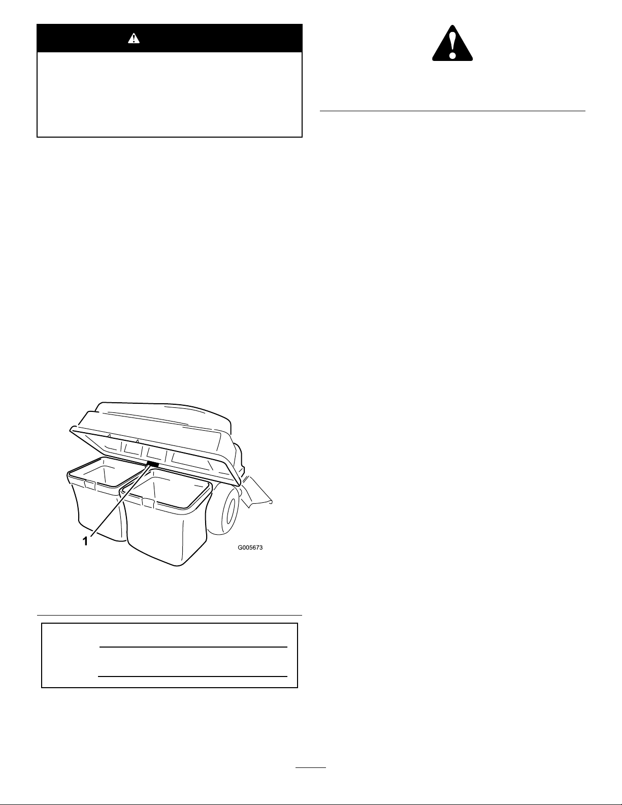
yourproductready.Figure1identiesthelocationofthe
modelandserialnumbersontheproduct.Writethenumbers
inthespaceprovided.
Figure1
1.Modelandserialnumberlocation
ModelNo.
SerialNo.
g000502
Figure2
1.Safety-alertsymbol
Thismanualuses2wordstohighlightinformation.
Importantcallsattentiontospecialmechanicalinformation
andNoteemphasizesgeneralinformationworthyofspecial
attention.
Contents
Safety...........................................................................3
TowingSafety.........................................................3
SafetyandInstructionalDecals.................................4
Setup............................................................................5
1PreparingtheMachine...........................................6
2InstallingtheW eight..............................................6
3RemovingtheGrassDeectorandBelt
Cover.................................................................7
4InstallingtheBafeandBlowerSupport...................8
5InstallingthePulleyAssembly,BeltCover,and
ShoulderBolt.....................................................10
6InstallingtheAttachmentMount............................10
7InstallingtheLatchRod........................................12
8AssemblingtheBaggerTop...................................12
9InstallingtheBaggerTop......................................13
10InstallingtheBlowerAssembly.............................14
11InstallingtheBlowerBeltandPoweredBagger
Cover................................................................15
12InstallingtheDischargeTubes.............................16
Operation....................................................................19
EmptyingtheGrassBags.........................................19
ClearingObstructionsfromtheBagger
System..............................................................19
RemovingtheBagger..............................................20
OperatingTips......................................................21
Maintenance.................................................................22
RecommendedMaintenanceSchedule(s)......................22
g005673
PreparingforMaintenance.......................................22
CleaningtheHoodScreen.......................................22
CleaningtheBaggerandBags...................................23
InspectingtheBlowerBelt.......................................23
ReplacingtheBlowerBelt........................................23
InspectingtheBagger.............................................24
InspectingtheMowerBlades...................................24
Storage........................................................................24
StoringtheBaggerAttachment.................................24
Troubleshooting...........................................................25
Thismanualidentiespotentialhazardsandhassafety
messagesidentiedbythesafety-alertsymbol(Figure2),
whichsignalsahazardthatmaycauseseriousinjuryordeath
ifyoudonotfollowtherecommendedprecautions.
©2017—TheToro®Company
8111LyndaleAvenueSouth
Bloomington,MN55420
Contactusatwww.Toro.com.
2
PrintedintheUSA
AllRightsReserved

Safety
truckortrailer.
•Donotusethemowerdeckwithoutthedischarge
•Usecarewhenloadingorunloadingthemachineintoa
WARNING
deectororgrasscatcher.
Whenthebaggerisinoperation,thebloweris
rotatingandcancutofforinjurehandsandngers.
•Beforeadjusting,cleaning,repairing,and
inspectingtheblower,andbeforeunclogging
thechute,shutofftheengineandwaitforall
movingpartstostop.Removethekey .
•Useastick,notyourhands,toremovean
obstructionfromtheblowerandtube.
•Keephandsandfeetawayfrommovingparts.
Donotmakeadjustmentswiththeengine
running.
WARNING
Debris,suchasleaves,grass,orbrushcancatch
re.Areintheengineareacancausepersonal
injuryandpropertydamage.
•Keeptheengineandmuferareafreeofdebris
accumulation.
•Takecarewhenopeningthebaggercoverto
keepdebrisfromfallingontotheengineand
muferarea.
•Allowthemachinetocoolbeforestoringit.
ThefollowinglistcontainssafetyinformationspecictoToro
productsandothersafetyinformationyoumustknow.
•Becomefamiliarwiththesafeoperationoftheequipment,
withtheoperatorcontrols,andsafetysigns.
•Useextracarewithgrasscatchersorotherattachments.
Thesecanchangetheoperatingcharacteristicsandthe
stabilityofthemachine.
•Parkthemachineonalevelsurface,disengagethedrives,
engagetheparkingbrake,andshutofftheenginebefore
leavingtheoperator'spositionforanyreasonincluding
uncloggingoremptyingthegrasscatcher.
•Ifyouremovethegrasscatcher,installanydischarge
deectororguardthatwasremovedtoinstallthegrass
catcher.Donotoperatethemachinewithouteitherthe
entiregrasscatcherorthegrassdeectorinplace.
•Donotleavegrassinthegrasscatcherforextended
periodsoftime.
•Grasscatchercomponentsaresubjecttowear,damage,
anddeterioration,whichcouldexposemovingpartsor
allowobjectstobethrown.Frequentlycheckcomponents
andreplacethemwithmanufacturer'srecommended
partswhennecessary.
TowingSafety
•Donotattachtowedequipmentexceptatthehitchpoint.
•Followtheattachmentmanufacturer'srecommendation
forweightlimitsfortowedequipmentandtowingon
slopes.
•Neverallowchildrenorothersinorontowedequipment.
•Onslopes,theweightofthetowedequipmentmaycause
lossoftractionandlossofcontrol.Reducetowedweight
andslowdown.
•Stoppingdistanceincreaseswiththeweightofthetowed
load.Travelslowlyandallowextradistancetostop.
•Makewideturnstokeeptheattachmentclearofthe
machine.
•Donottowaloadthatweighsmorethanthetowing
machine.
•Followtherecommendationsforaddingorremoving
weightsasdescribedintheOperator’sManualforthe
machine.
•Donotuseagrasscatcheronsteepslopes.Aheavy
grasscatchercouldcauselossofcontroloroverturnthe
machine.
•Slowdownanduseextracareonhillsides.Mowslopes
sidetoside.Turfconditionscanaffectthestabilityof
themachine.Useextremecautionwhileoperatingnear
drop-offs.
•Keepallmovementonslopesslowandgradual.Donot
makesuddenchangesinspeed,directions,orturning.
•Thegrasscatchercanobstructtheviewtotherear.Use
extracarewhenoperatingthemachineinreverse.
3
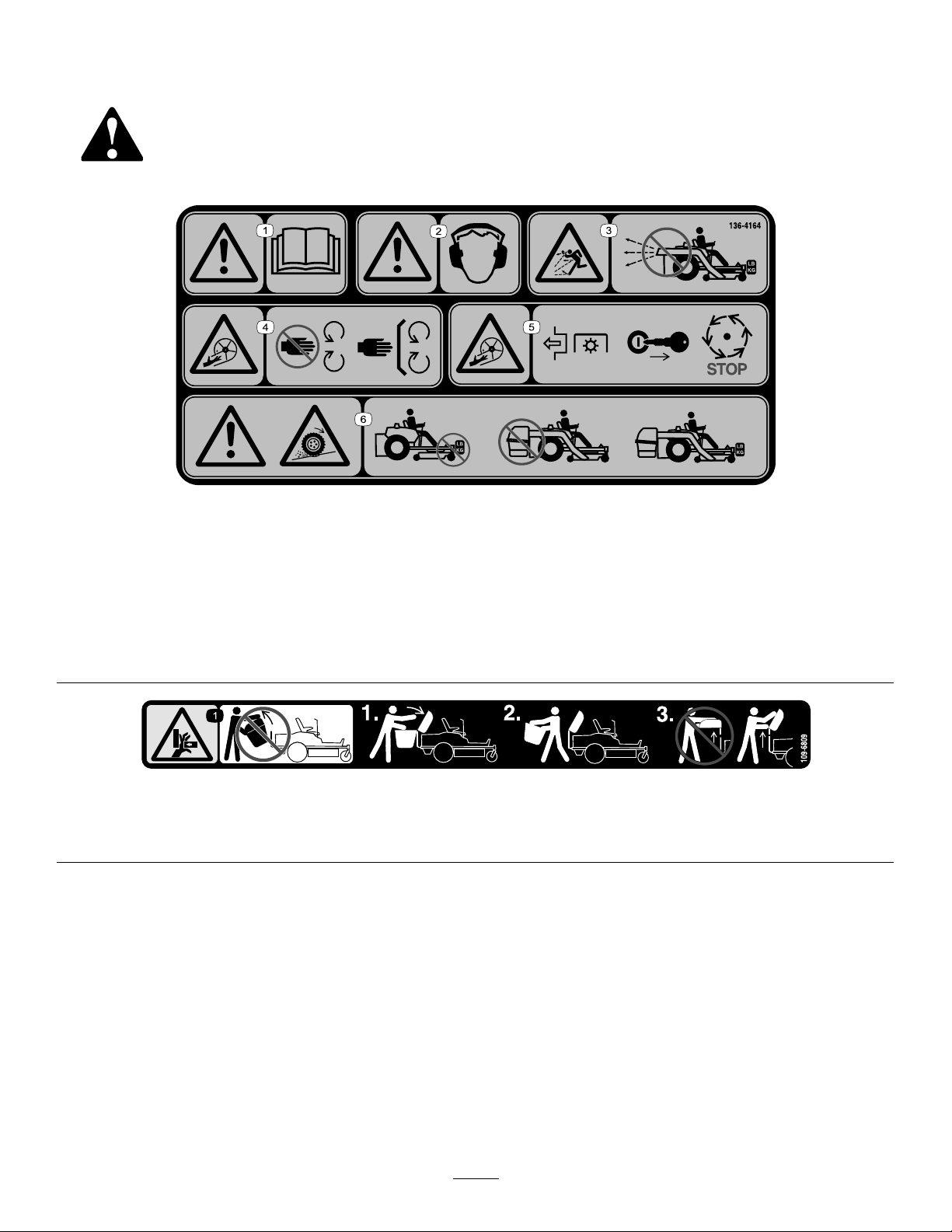
SafetyandInstructionalDecals
Safetydecalsandinstructionsareeasilyvisibletotheoperatorandarelocatednearanyareaofpotential
danger.Replaceanydecalthatisdamagedormissing.
decal136-4164
136-4164
1.Warning—readtheOperator’sManual.4.Cutting/dismembermenthazard,impeller—keepawayfrom
2.Warning—hearingprotectionmustbeworn.
3.Thrownobjecthazard—donotoperatetheblowerwithoutthe
entiresysteminstalledandlatched.
movingparts;keepallguardsandcoversinplace.
5.Cutting/dismembermenthazard,impeller—disengagethe
PTO,removethekey,andwaitforallmovingpartstostop.
6.Warning;lossoftraction—donotoperatewithonly
counterbalanceweightsinstalled;donotoperatewithonly
E-ZV acinstalled;operateonlywithbothE-ZVacand
counterbalanceweightsinstalled.
109-6809
1.Crushinghazardofhand—Donotremovethewholebaggerfromthemachine.Step1:Openthebaggertop.Step2:Removethe
bag(s)fromthebagger.Step3:Donotremovethebaggertopwhenitisclosed;openthebaggertopandthenremoveit.
decal109-6809
4

Setup
LooseParts
Usethechartbelowtoverifythatallpartshavebeenshipped.
ProcedureDescription
1
2
3
4
5
6
7
8
Nopartsrequired
Weighttray1
Leftweight-traymount
Rightweight-traymount1
Suitcaseweight—16kg(35lb)
Retainingrod1
Bolt(3/8x1-1/4inches)
Flangenut(3/8inch)
Carriagebolt(3/8x1inch)
Self-tappingbolt(5/16x3/4inch)
Nopartsrequired
Blowersupport1
Hexwasher-headscrew(3/8x3/4inch)
Bafe
Carriagebolt(5/16x3/4inch)
Flangenut(5/16inch)
Pulleyassembly1
Beltcover1
Stabilizerbracket
Carriagebolt(5/16x3/4inch)
Locknut(5/16inch)
Self-tappingscrew(5/16x3/4inch)
Bolt(5/16x1inch)
Pivotframe
Hairpincotter2
Rod2
Washer2
Latchrod1
Hairpincotter1
Baggertop1
Baggerscreen1
Hairpincotter2
Qty.
Use
–
1
1
2
4
2
2
–
2
1
4
4
1
2
4
2
2
1
Preparethemachine.
Installtheweight.
Removethegrassdeectorandbelt
cover.
Installthebafeandblowersupport.
Installthepulleyassemblyandbelt
cover.
Installtheattachmentmount.
Installthelatchrod.
Assemblethebaggertop.
9
10
11
12
GrassBag
Blowerassembly1Installtheblowerassembly .
Poweredbaggercover1
Blowerbelt1
Uppertube1
Screw(1/4x3/4inches)
Washer(1/4inch)
Locknut(1/4inch)
Lowertube1
5
2Installthebaggertop.
Installtheblowerbeltandpowered
baggercover.
2
2
2
Installthedischargetubes.

Determinetheleftandrightsidesofthemachinefromthenormaloperatingposition.
1
PreparingtheMachine
NoPartsRequired
Procedure
Performthefollowingproceduretopreparethemachinefor
attachingtheblowerandnishingkit.
1.Parkthemachineonalevelsurface.
2.Disengagetheblade-controlswitch,engagetheparking
brake,andmovethemotion-controlleversoutwardto
theNEUTRAL-LOCKposition.
3.Shutofftheengineandremovethekey.
4.Ensurethatthemachineissecurefrommovement
beforeyoubegintoworkonit.
5.Repairallbentordamagedareasofmachinedeckand
replaceanymissingparts.
6.Cleanthemachineofanydebrisonthemachinedeck
orrearpartofthemachinetoeaseinstallation.
2
InstallingtheWeight
Partsneededforthisprocedure:
1Weighttray
1
Leftweight-traymount
1Rightweight-traymount
1
Suitcaseweight—16kg(35lb)
1Retainingrod
2
Bolt(3/8x1-1/4inches)
4
Flangenut(3/8inch)
2
Carriagebolt(3/8x1inch)
2
Self-tappingbolt(5/16x3/4inch)
Procedure
CAUTION
Thebaggerchangestheweightdistributionofthe
machine.Operatingthemachinewithoutthefront
weightsmaycauseanunstablecondition,which
couldresultinalossofcontrol.
Ensurethefrontweightsareproperlyinstalled
beforeoperatingthemachinewiththebagger
attachment.
1.Removetheexistingboltandnutfromtheleftand
rightsideoftheplatformwhereyouwillinstallthe
weight-traymounts.
2.Usethe2self-tappingbolts(5/16x3/4inch),2bolts
(3/8x1-1/4inches),andangenuts(3/8inch)to
securetheleftandrightweight-traymountstothe
machine(Figure3).
6
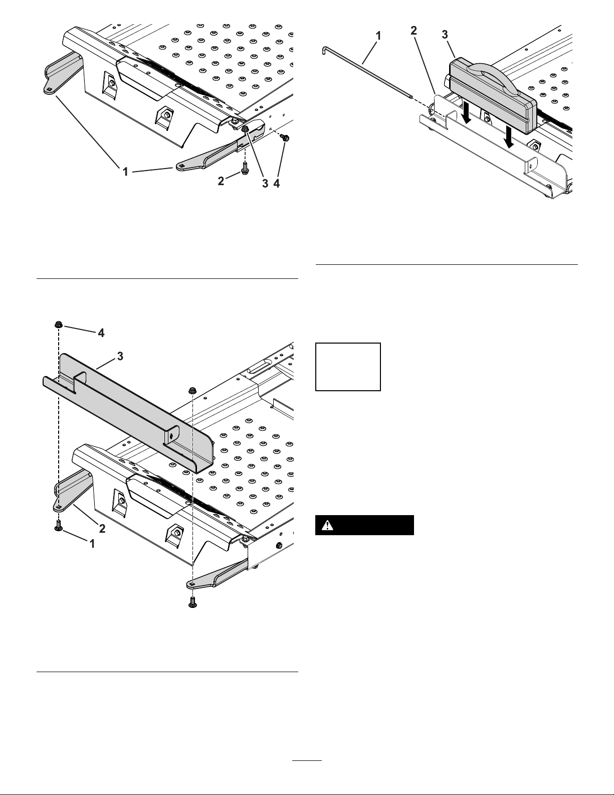
Figure3
Cutawayview
g196533
g196560
Figure5
1.Weight-traymounts
2.Bolt(3/8x1-1/4inches)4.Self-tappingbolt(5/16x
3.Usethe2carriagebolts(3/8x1inch)andangenuts
tosecuretheweighttraytothemounts(Figure4).
3.Flangenut(3/8inch)
3/4inch)
1.Retainingrod
2.Weighttray
5.Inserttheretainingrodintothetrayandrotateitinto
thelockedposition(Figure5).
Important:Removethesuitcaseweightwheneveryou
removethebaggerattachment.
3.Suitcaseweight
3
RemovingtheGrass
DeectorandBeltCover
NoPartsRequired
Procedure
Figure4
1.Carriagebolt(3/8x1inch)
2.Weight-traymount
4.Insertthesuitcaseweightintotheweighttraywiththe
groovesidefacingtowardthefrontofthemachine
(Figure5).
3.Weighttray
4.Flangenut(3/8inch)
WARNING
Anuncovereddischargeopeningcouldallowthe
lawnmowertothrowobjectsintheoperator’sor
bystander’sdirectionandresultinseriousinjury.
Also,contactwiththebladecouldoccur.
g196549
Neveroperatethelawnmowerunlessyouinstalla
mulchplate,dischargedeector,orgrass-collection
system.
Inspectthegrassdeectorfordamagebeforeeachuse.
Replaceanydamagedpartsbeforeuse.
1.Disengagethespringfromthenotchinthedeector
bracketandremovethecotterpin(internationalmodels
only),slidetherodoutoftheweldeddeckbrackets,
spring,anddischargedeector(Figure6).
7
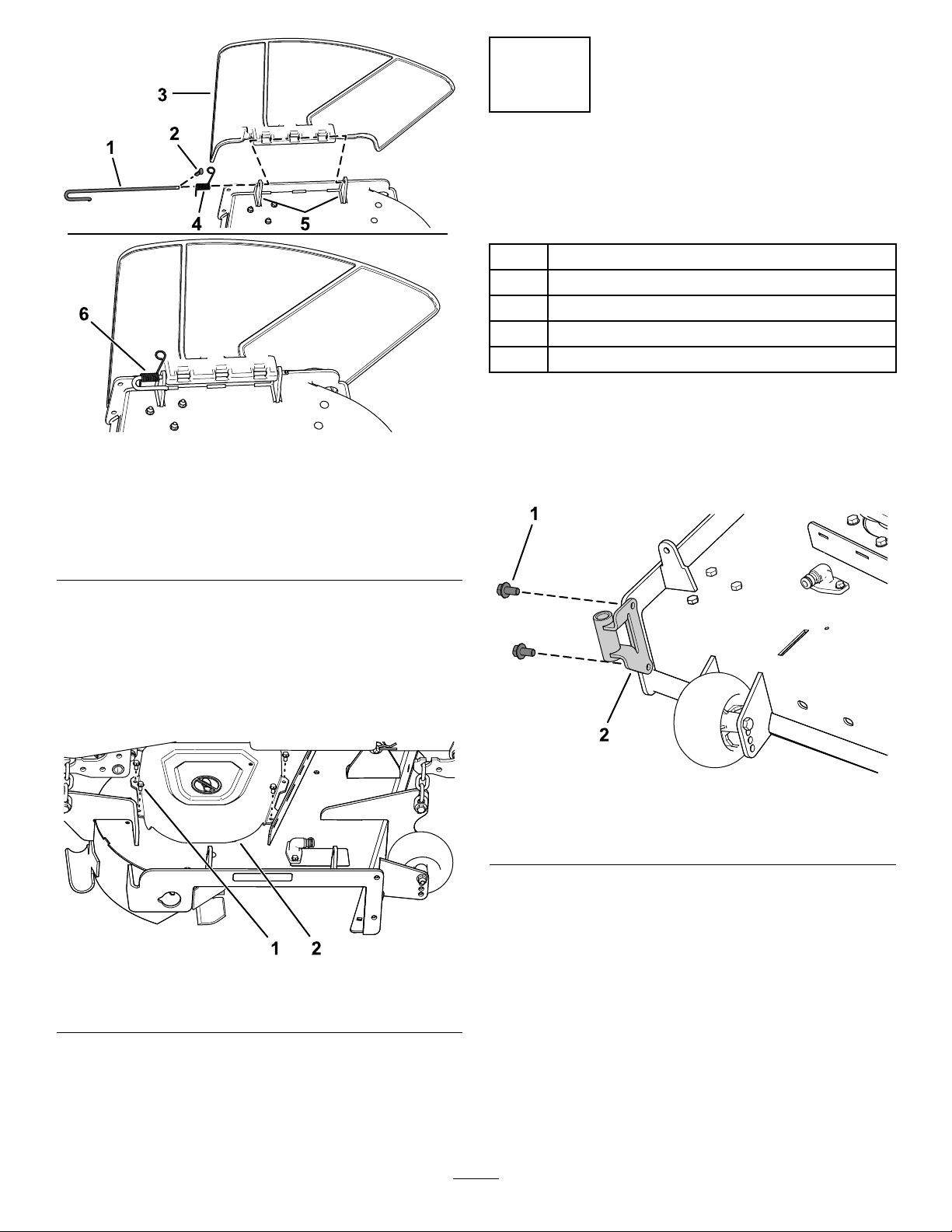
Figure6
1.Rod
2.Cotterpin(international
modelsonly)
3.Deector6.Springinstalledoverthe
4.Spring
5.Deckbrackets
rod
4
InstallingtheBafeand
BlowerSupport
Partsneededforthisprocedure:
1Blowersupport
2
Hexwasher-headscrew(3/8x3/4inch)
1
Bafe
4
Carriagebolt(5/16x3/4inch)
4
Flangenut(5/16inch)
Procedure
g190642
1.Installtheblowersupporttothemowerdeckusing
2hexwasher-headscrews(3/8x3/4inch)asshown
inFigure8.
2.Removethedeector(Figure6).
3.Removethe4screws(1/4x1/2inch)securingthe
rightbeltcover,andremovethebeltcover(Figure7).
Note:Retainthe4screws(1/4x1/2inch)for
installationinProcedure5InstallingthePulley
Assembly,BeltCover,andShoulderBolt(page10).
Figure7
1.Screw(1/4x1/2inch)
2.Beltcover
g201299
Figure8
1.Hexwasher-headscrew
(3/8x3/4inch)
g200974
2.Blowersupport
8
2.Removetheexistingboltandnutfromthemowerdeck
(Figure9).
Important:For48-inchand60-inchmowerdecks,
thereisonlyoneboltandnutthatyoucanremove.
For54-inchmowerdeck,removetheboltandnut
asshowninFigure9.
g206496
Figure10
54-inchmowerdeckshown
Figure9
1.Existingbolt2.Existingnut
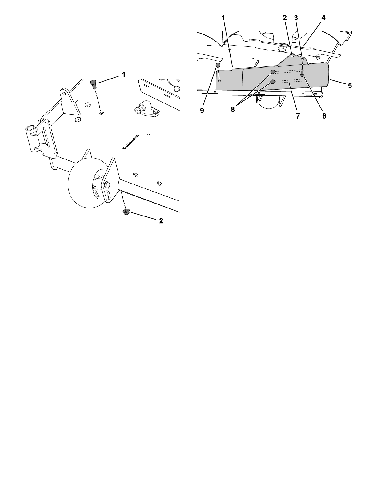
3.Installtheleftsideofthebafeusingacarriagebolt
(5/16x3/4inch)andangenut(5/16inch)asshown
inFigure10.
4.Loosenthe2carriagebolts(5/16x3/4inch)inthe
bafeslots,andslidethebafeuntiltheholealigns
withtheholeinthemowerdeck(Figure10).
5.InstallbafeasshowninFigure10.
1.Innerbafe
2.Holefor48-inchand
60-inchmowerdeck
installation.
3.Holefor54-inchmower
deckinstallation.
4.Rightblade9.Installthiscarriagebolt
g206498
5.Outerbafe
6.Installthiscarriagebolt
(5/16x3/4inch)and
angenut(5/16inch)after
slidingthebafe.
7.Slotsinthebafe
8.Loosenthese2carriage
bolts(5/16x3/4inch)and
2angenut(5/16inch).
(5/16x3/4inch)and
angenut(5/16inch)rst.
Important:Ensurethatyouusethecorrecthole
forthebafe;refertoFigure10.
6.Tightenthe2carriagebolts(5/16x3/4inch)inthe
bafeslots(Figure10).
9

5
InstallingthePulley Assembly,BeltCover, andShoulderBolt
Partsneededforthisprocedure:
1Pulleyassembly
1Beltcover
g201435
Figure12
Procedure
1.Removethenutandwasherfromtherightmowerdeck
pulley.
2.Installthepulleyassemblytotherightmowerdeck
pulleywiththepreviouslyremovednutandwasher
(Figure11).
Important:For48-inchmowerdecks,usethe
smallblowerpulley.
For54-inchand60-inchmowerdecks,usethe
largeblowerpulley.
3.Torquethenutto136to149N∙m(100to110ft-lb).
1.Beltcover
6
InstallingtheAttachment Mount
Partsneededforthisprocedure:
1
Stabilizerbracket
2
Carriagebolt(5/16x3/4inch)
4
Locknut(5/16inch)
2
Self-tappingscrew(5/16x3/4inch)
2
Bolt(5/16x1inch)
1
Pivotframe
2Hairpincotter
2Rod
2Washer
2.Screw(1/4x1/2inch)
Figure11
54-inchmowerdeckshown
1.Existingpulleynut
2.Existingwasher
3.Blowerpulley
4.Installthenewbeltcoveroverthepulleyassembly
usingthe4previouslyremovedscrews(1/4x1/2inch)
asshowninFigure12.
4.Existingdeck(spindle)
pulley
5.Spindle
Procedure
g201880
1.Removetheexisting2bolts,2nuts,andhitchbracket
fromthebottomoftheengineguard(Figure13).
10

Figure13
g030494
1.Nut3.Bolt
2.Existinghitchbracket
g201215
1.Machineframe4.Bolt(5/16x1inch)
2.Locknut(5/16inch)5.Pivotframe
3.Hole
Figure15
g201214
2.Installthestabilizerbrackettotheengineguardusing2
carriagebolts(5/16x3/4inch)and2locknuts(5/16
inch)asshowninFigure14.
Figure14
1.Stabilizerbracket3.Locknut(5/16inch)
2.Carriagebolt(5/16x3/4
inch)
5.Positionthepivotframeupward,andsecurethepivot
frametothebottomofthemachineframeusing2
self-tappingscrews(5/16x3/4inch)asshownin
Figure16.
g030494
g028174
Figure16
3.Removetheexisting2self-tappingscrewsfromthe
bottomofthemachineframe(Figure16).
4.Looselyinstallthepivotframetothemachineframe
using2bolts(5/16x1inch)and2locknuts(5/16inch)
asshowninFigure15.
1.Self-tappingscrew(5/16x
3/4inch)
2.Pivotframe
6.Tightenthe2bolts(5/16x1inch)and2locknuts
(5/16inch)asshowninFigure15.
7.Installthebent,aredendofarodintothekeyedslot
intheleftsideofthemachineframe,andmovetherod
rearwardtoseatitintheframe(Figure17).
Note:Repeatthisstepfortherightsideofthe
machine.
11

Figure17
Leftsideshown
1.Pivotframehole4.Supportrod
2.Washer
3.Hairpincotter
8.Insertthebentendsoftherodsintotheattachment
mountasshowninFigure17andsecuretheendof
eachrodwithawasherandhairpincotter.
5.Keyedslot(existing)
6.Bent,aredendoftherod
7
InstallingtheLatchRod
Partsneededforthisprocedure:
1Latchrod
1Hairpincotter
Procedure
Installthelatchrodwithahairpincotter(Figure18).
g028306
Figure18
1.Hairpincotter2.Latchrod
8
AssemblingtheBaggerTop
Partsneededforthisprocedure:
1Baggertop
1Baggerscreen
2Hairpincotter
Procedure
1.Turnthebaggertopover.
g201213
12

2.InstallthescreenasshowninFigure19andensurethat
G016265
itslopesdowntowardthecollectionbags.
Note:Makesurethatthescreenssnapintoplaceand
thetabsengagethebaggertop.
9
InstallingtheBaggerTop
Partsneededforthisprocedure:
2
GrassBag
Procedure
1.Installthebaggertoptothebaggerframe.
2.Slidethebracketsoverthepostsinthebaggerframe
andinstallthecircularcotterpinintotheholeinthe
righthandpost(Figure20).
3.Rotatethebaggerhooddowntotheoperatingposition.
Note:Toremovethecircularcotterpin,continueto
rotateitinthesamedirectionasinstalled.
1.Baggertop
2.Screen
3.Screentab
Figure19
4.Slotinbaggertop
5.Hairpincotter
g016265
Figure20
g201881
1.Baggerhood
2.Baggerframe
3.Bracket,baggerhood
13
4.Circularcotterpin
5.Post

4.Liftthebaggertopandinstallthebagsbyslidingthe
1
2
3
4
bagframehooksontotheretainingbrackets(Figure
21).
Figure21
1.Bag3.Retainingbracket
2.Baggerframe4.Bagframehook
5.Lowerthebaggertopontothebags(Figure22).
10
InstallingtheBlower Assembly
Partsneededforthisprocedure:
1Blowerassembly
Procedure
WARNING
Anuncovereddischargeopeningallowsthelawn
mowertothrowobjectstowardyouorbystanders,
resultinginseriousinjury.Also,contactwiththe
bladecouldoccur.
g033032
•Neveroperatethelawnmowerwithoutacover
plate,amulchplate,oragrasschuteand
catcher.
•Makesurethatthegrassdeectorisinstalled
whenyouremovethegrasschuteandcatcher.
Figure22
6.Securethehoodwiththelatch(Figure22).
Important:Installtheside-dischargechutewhenyou
removethebaggerandblower.
Important:Saveallthehardwareandtheside-discharge
chute.
1.Ifnecessary,installthebeltontotheblowerpulley
(Figure25).
2.Inserttheblowerpivotpinintotheblowersupportand
rotatetheblowerassemblyinwardtowardthemachine
(Figure23).
g033030
Note:Theblowerassemblyshouldautomaticallylatch
asshowninFigure24.
14

Figure23
1.Blowerassembly3.Blowersupport
2.Blowerpivotpin
11
InstallingtheBlowerBelt andPoweredBaggerCover
Partsneededforthisprocedure:
1Poweredbaggercover
1Blowerbelt
g201514
Procedure
1.Installthebeltaroundtheblowerpulley(Figure25and
Figure26);referto10InstallingtheBlowerAssembly
(page14).
Usethefollowingbeltbasedonthemowerdeck
size:
1.Blowerlatch
Figure24
48-inchMower
Deck
ToroPartNo.
127-0074
g201893
1.Idler/tensionpulley
2.Blowerpulley4.Drivepulley
BlowerBeltRouting
54-inchMower
ToroPartNo.
127-0075
Figure25
Deck
60-inchMower
Deck
ToroPartNo.
127-0076
g201516
3.Blowerbelt
15

Figure26
1.Blowerpulley5.Idlerarm
2.Blowerinposition(housing
portionremovedfor
illustrativepurposes)
3.Spring7.Idler/tensionpulley
4.Idler-pulleypost8.Blowerbelt
6.Drivepulley
12
InstallingtheDischarge Tubes
Partsneededforthisprocedure:
1Uppertube
2
Screw(1/4x3/4inches)
2
Washer(1/4inch)
2
Locknut(1/4inch)
1Lowertube
g201513
Procedure
Important:Makesurethatthemowerdeckisinthe
lowestheight-of-cutpositionbeforeinstallingthe
dischargetubes.
Note:Remembertoinstallthegrassdeectorwhenyou
removethebaggerfromthemower.
2.Ensurethatthebeltremainsaligneldtotheblower
pulleywhileyouareinstallingtheblowerassembly.
3.Pullthespringloadedidlerpulleyawayfromthexed
springpost,androutethebeltaroundthemowerdeck
pulley(Figure26).
Note:Ensurethatthebeltisroutedaroundtheblower
pulleycorrectly.
4.Routethebeltaroundthedrivepulleyasillustratedin
Figure25andFigure26.
5.Installthepoweredbaggercoveroverthebeltcover,
andsecureitbytighteningtheknob(Figure27).
1.DisengagethePTOandengagetheparkingbrake.
2.Shutofftheengineandremovethekey.
3.Lowerthemowerdecktothelowestheight-of-cut
position.
4.Removethebagsforviewingthetubeunderthehood.
5.Lowerandlatchthehood.
6.Usebothlatchestoattachthelowertubetotheblower
assembly(Figure28).
Note:Ensurethenotchinthelowertubeisatthe
bottomwheninstalled(Figure30).
Figure27
1.Knob3.Beltcover
2.Poweredbaggercover
g201515
16

3
G018444
1
2
G018440
1
2
3
Figure29
g020776
1 2
4 3
1.Uppertube3.Baggerhood
2.Rubbersealprotrudingout
12.Aligntheuppertubeholestomatchthedimplesonthe
surfaceofthelowertube.
g018440
g018444
Figure28
LowerDischargeTubeLatch
1.Blowerassembly3.Latch
2.Upperlatch
Note:Ensurethatthesideproleappearsasshown
inFigure30.
Note:Donotusetheopenholenearthemolded
arrowheads.
7.Makenoteofwherethe2boltsintheuppertubeare
installed.
Note:Theholenearthemoldedarrowheadswillnot
beused.
8.Removethe2boltsinthelowerendoftheuppertube.
9.Usethe2holesasatemplateforthelowertube.
Note:Retainthehardware.
10.Inserttheupperend(noholes)oftheuppertube
throughthetubesealinthehoodbypushingthetube
inuntilthetubecontactstheinsideofthehood.
11.Pulltheuppertubeoutslightlysothatthesealextends
outwardandoverthelowertube(Figure29).
1.Uppertube
2.Existinghole(bolt
removed)
g020776
Figure30
3.Notchatthebottomofthe
tubewheninstalled
4.Lowertube
13.Usingtheexistingholesintheuppertubeasatemplate,
drill2holes,6.5mm(1/4inch)diameter,throughthe
dimplesonthelowertube(Figure31).
17

G018439
4
2
3
3
1
6
5
18.Securethetubestogetherwiththenuts(1/4inch)as
showninFigure31.
19.Inserttheupperdischargetubethroughthetubeseal
inthehood.
20.Pulltheuppertubeoutslightlysothatthesealextends
outwardandovertheblowerassembly(Figure29).
21.Usebothlatchestoattachthelowertubetotheblower
assembly(Figure28).
Figure31
DrillingLowerDischargeTube
1.Dimples4.Uppertube
2.Lowertube
3.Drill6.5mm(1/4inch)
diameterhole
5.Installscrew(1/4x3/4
inch),washer(1/4inch),
andlocknut(1/4inch)
here.
6.Uppertube—existing
holes
14.Removetheupperandlowertubesfromthemachine.
15.Slidethetubestogetherandaligntheholes.
16.Installthewashers(1/4inch)ontothebolts(Figure
31).
17.Usingahexkeytool,installthescrews(1/4x3/4inch)
andwashers(1/4inch)fromtheinsideofthelower
tubeandthroughtheexistingholesintheuppertube
(Figure31).
g018439
18

Operation
G005758
G005672
1
2
3
4
Note:Determinetheleftandrightsidesofthemachine
fromthenormaloperatingposition.
WARNING
Toavoidpersonalinjury,followtheseprocedures:
•Becomefamiliarwithalloperatingandsafety
instructionsinthe
Operator's Man ual
mowerbeforeusingthisattachment.
•Neverremovethedischargetube,bags,bagger
hood,orthechutewhiletheengineisrunning.
•Alwaysshuttheengineoffandwaitforall
movingpartstostopbeforeclearingan
obstructionfromthebaggingsystem.
•Neverperformmaintenanceorrepairswhilethe
engineisrunning.
EmptyingtheGrassBags
forthe
Becarefulwhenliftingorhandlingagrassbagthatisfull.To
emptythegrassbags:
1.Parkthemachineonalevelsurface.
2.Disengagetheblade-controlswitch,engagetheparking
brake,andmovethemotion-controlleversoutwardto
theNEUTRAL-LOCKposition.
3.Shutofftheengineandremovethekey.
4.Raisethebaggerhood(Figure32).
Figure32
5.Compressthedebrisintothebags.
6.Withbothhands,liftuponthebagandunhookitfrom
theretainingbracket,emptythebag.
7.Repeattheprocedurefortheotherbag.
8.Installthebagsbyslidingthebagframehooksontothe
retainingbrackets(Figure33).
g005672
Figure33
1.Bag3.Retainingbracket
2.Baggerframe4.Bagframehook
9.Lowerthebaggerhoodontothebags.
ClearingObstructionsfrom theBaggerSystem
WARNING
Whenthebaggerisinoperation,thebloweris
rotatingandcancutofforinjurehandsandngers.
•Beforeadjusting,cleaning,repairingand
inspectingtheblower,andbeforeunclogging
thechute,turnofftheengineandwaitforall
g005758
movingpartstostop.Removethekey .
•Useastick,notyourhands,toremovean
obstructionfromtheblowerandtube.
•Keepyourface,hands,feet,andanyotherpart
ofyourbodyorclothingawayfromconcealed,
moving,orrotatingparts.
1.Parkthemachineonalevelsurface.
2.Disengagetheblade-controlswitch,engagetheparking
brake,andmovethemotion-controlleversoutwardto
theNEUTRAL-LOCKposition.
19

3.Shutofftheengineandremovethekey.
4.Emptythebags.
5.Unlatchthelowertube.
6.Removethetubesfromthebagger.
7.Useastickorsimilarobject,notyourhands,toremove
andcleartheobstructionfromthetubeassembly .
Note:Inmostcases,youcanshakethedebrisoutof
thetubes.
8.Iftheblowerassemblyisplugged,removetheplastic
beltcover,unlatchthebaggerblowerassembly,remove
thebelt,andswingitopen.
9.Useastickorsimilarobject,notyourhands,toremove
andcleartheobstructionfromtheblowerassembly.
10.Afteryouremovetheobstruction,installthecomplete
baggersystemandresumeoperation.
RemovingtheBagger
WARNING
Componentsaroundtheenginewillbehotif
themachinehasbeenrunning.T ouchinghot
componentscancauseburns.
•Donottouchenginecomponentswhenhot.
•Allowenginetocoolbeforeremovingthebagger.
CAUTION
Failingtoremovethefrontbaggerweights
andoperatingthemachinewithoutthebagger
attachmentmaycauseanunstableconditionwhich
couldresultinalossofcontrol.
Alwaysremovethefrontweightswhenremoving
thebaggerattachment.
Removethebaggerbyrepeatingthesetupsectionsfromthe
InstallationInstructionsandOperator’ sManualinreverseorder.
Alwaysremovethefrontbafesandfrontweightswhen
removingthebaggerattachments.
Important:Installtheside-dischargechutewhenyou
removethebaggerandblower.
Note:Itisonlynecessarytoremovethecutoffbafewhen
installingamulchingkit.
20

OperatingTips
TipsforBagging
RememberingtheSizeofthe
MachinewiththeAttachment
Rememberthatthemachineislongerandwiderwiththis
attachmentinstalled.Byturningtoosharplyinconned
placesyoumaydamagetheattachment.
CAUTION
Asthebaggerlls,extraweightisaddedtotheback
ofthemachine.Ifyoustopandstartsuddenlyon
hills,youmaylosesteeringcontrolorthemachine
maytip.
•Donotstartorstopsuddenlywhengoinguphill
ordownhill.Avoiduphillstarts.
•Ifyoudostopthemachinewhengoinguphill,
disengagethebladecontrol.Thenbackdown
thehillusingaslowspeed.
Trimming
Alwaystrimwiththeleftsideofthemower.Donottrimwith
therightsideofthemowerbecauseyoucoulddamagethe
baggerchuteanddischargetube.
CuttingHeight
Donotsetthemowercuttingheighttoolowbecauselong
grasssurroundingthemowercanpreventairfromgetting
underthemowerandenteringthebaggingsystem.Ifenough
airdoesnotgetunderthemower,thebaggingsystemwill
plug.
CuttingFrequency
Cutthegrassoften,especiallywhenitgrowsrapidly.Youwill
needtocutyourgrasstwiceifitgetsexcessivelylong.
CuttingTechnique
Forbestlawnappearance,besuretoslightlyoverlapthe
mowerintothepreviouslycutarea.Thishelpsreducethe
loadontheengineandreducesthechanceofpluggingthe
chuteanddischargetube.
BaggingSpeed
MostoftenyouwillbagwiththemowerthrottleintheFAST
positionanddriveatanormalgroundspeed.However,
inextremelydryanddustygrass,youmaywanttoslightly
reducethethrottlespeedandincreasethegroundspeedof
themower.Thebaggingsystemmayplugifyoudrivetoo
fastandtheenginespeedgetstooslow.Onhills,itmay
benecessarytoslowthemowergroundspeed.Thishelps
maintaintheenginespeedandbaggingefciency .Mow
downhillwheneverpossible.
•Avoidsuddenturnsorrapidspeedchangeson
slopes.
•Neveroperatethemachinewithoutthebagger
attachmentandthefrontweightsstillinstalled.
BaggingLongGrass
Excessivelylonggrassisheavyandmaynotbepropelled
completelyintothegrassbags.Ifthishappens,thedischarge
tubeandchutemayplug.Toavoidpluggingthebagging
system,mowthegrassatahighheightofcut,thenlowerthe
mowertoyournormalcuttingheightandrepeatthebagging
process.
BaggingWetGrass
Alwaystrytocutgrasswhenitisdrybecauseyourlawnwill
haveaneatappearance.Ifyoumustcutwetgrass,usethe
conventionalsidedischargefeatureofthemower.Several
hourslater,whentheclippingsaredry,installthecomplete
baggerattachmentandvacuumupthegrassclippings.
SignsofPlugging
Asyouarebagging,asmallamountofgrassclippings
normallyblowoutthefrontofthemower.Anexcessive
amountofclippingsblowingoutindicatesthatthebagsare
fullorthesystemisplugged.
21

Maintenance
Note:Determinetheleftandrightsidesofthemachinefromthenormaloperatingposition.
RecommendedMaintenanceSchedule(s)
MaintenanceService
Interval
Aftertherst8hours
Aftereachuse
Every25hours
Every100hours
MaintenanceProcedure
•Inspecttheblowerbelt.
•Inspectthebagger.
•Cleanthehoodscreen.
•Cleanthebagger.
•Inspecttheblowerbelt.
•Inspectthebagger.
WARNING
Ifyouleavethekeyinthekeyswitch,someonecouldaccidentlystarttheengineandseriouslyinjure
youorotherbystanders.
Removethekeyanddisconnectthewirefromthesparkplugbeforeyoudoanymaintenance.Setthewire
asidesothatitdoesnotaccidentallycontactthesparkplug.
WARNING
Enginescanbecomehotwhentheyareoperating.Severeburnscanoccurfromcontactinghotsurfaces.
Allowengines,especiallythemufer,tocoolbeforetouching.
WARNING
Debris,suchasleaves,grass,orbrushcancatchre.Areintheengineareacancausepersonalinjury
andpropertydamage.
•Keeptheengineandmuferareafreeofdebrisaccumulation.
•Takecarewhenopeningthebaggercovertokeepdebrisfromfallingontotheengineandmuferarea.
•Allowthemachinetocoolbeforestoringit.
PreparingforMaintenance
Dothefollowingstepsbeforepreformingmaintenanceon
themachine:
1.Parkthemachineonalevelsurface.
2.DisengagethePTO ,movethemotioncontrolleversto
theNEUTRAL-LOCKposition,andengagetheparking
brake.
3.Shutofftheengineandremovethekey.
4.Cleanthemowerofanydebrisonthedeckorrearpart
ofthemowertoeasemaintenance.
CleaningtheHoodScreen
ServiceInterval:Aftereachuse
1.Openthebaggerhood.
2.Cleanthedebrisfromthescreen.
3.Closethebaggerhood.
22

CleaningtheBaggerand Bags
ServiceInterval:Aftereachuse
1.Washtheinsideandoutsideofthebaggerhood,bags,
tube,andtheundersideofthemower.
Note:Useamildautomotivedetergenttoremovedirt.
2.Makesurethatyouremovemattedgrassfromallparts.
3.Afterwashingallparts,letthemdrythoroughly.
Note:Withallpartsinstalled,startandrunthemachinefor
aminutetoassistindrying.
InspectingtheBlowerBelt
ServiceInterval:Aftertherst8hours
Every25hours
Checkbeltsforcracks,frayededges,burnmarksoranyother
damage.Replacedamagedbelts.
4.Removetheblowerfromthemowerdeck.
5.Removetheexistingbaggerbeltfromtheblower
pulleys.
6.Installthenewbeltaroundtheblowerpulleys(Figure
34).
7.Installtheblowerontotheblowersupport.
8.Installthenewbeltaroundthemower-deckpulley
(Figure34).
9.Pullbackonthespringloadedidlerpulleyandinstall
thebeltontothespring-loadedidlerpulley(Figure34).
ReplacingtheBlowerBelt
1.Removetheplasticbeltcover.
2.Pullbackonthespring-loadedidlerpulleytorelieve
thebelttension(Figure34).
Figure34
g202246
1.Blowerpulley4.Mowerdeck
2.Blowerinposition(housing
portionremovedfor
illustrativepurposes)
3.Drivepulley6.Blowerbelt
3.Removetheexistingbaggerbeltfromthemower-deck
pulley.
5.Idler/tensionpulley
23

InspectingtheBagger
ServiceInterval:Every100hours
Storage
Aftertherst8hours
1.Checktheuppertube,lowertube,baggerhood,and
theblowerassembly.
Note:Replacethesepartsiftheyarecrackedor
broken.
2.Checkthebags,baggerframe,andscreen.
Note:Replaceanypartsthatarecrackedorbroken.
3.Tightenallnutsboltsandscrews.
InspectingtheMower Blades
1.Inspectthemowerbladesregularlyandwhenevera
bladestrikesaforeignobject.
2.Ifbladesarebadlywornordamaged,installnewblades;
refertoyourmachineOperator'sManualforcomplete
blademaintenance.
StoringtheBagger Attachment
1.Cleanthebaggerattachment;refertoCleaningthe
BaggerAttachment.
2.Inspectthebaggerattachmentfordamage;referto
InspectingtheBaggerAttachment.
3.Ensurethatthegrassbagsareemptyandthoroughly
dry.
4.Storethebaggerinaclean,dryplace,outofdirect
sunlight.Thisprotectstheplasticpartsandextendsthe
lifeofthebagger.Ifyoumuststorethebaggeroutside,
coveritwithaweatherproofcover.
24

Troubleshooting
Problem
Thereisabnormalvibration.
Reducedbaggingperformance
Theblowerandtubesplugtoofrequently.
PossibleCauseCorrectiveAction
1.Thecuttingblade(s)arebentor
unbalanced.
2.Theblade-mountingboltisloose.2.Tightentheblade-mountingbolt.
3.Thereisalooseblowerpulleyorpulley
assembly.
4.Thebaggerbeltisworn.4.Replacethebelt.
5.Theblowerfanblade(s)arebentor
unbalanced.
1.Theenginespeedistoolow.
2.Thescreeninthebaggerhoodis
plugged.
3.Thebaggerbeltisloose.3.Replacethebaggerbelt.
4.Thereisapluggedtubeorblower.4.Locateandremovethepluggeddebris.
5.Thebagsarefull.
1.Thebagsaretoofull.1.Dumpmorefrequently.
2.Theenginespeedistoolow.
3.Thegrassistoowet.
4.Thegrassistoolong.
5.Thescreeninthebaggerhoodis
plugged.
6.Thegroundspeedistoofast.6.Drivesloweratfullthrottle.
7.Thebaggerbeltisworn.7.Replacethebelt.
1.Installnewcuttingblade(s).
3.Tightentheappropriatepulley.
5.ContactanAuthorizedServiceDealer.
1.Alwaysoperatetheengineatfull
throttle.
2.Removedebris,leaves,orgrass
clippingsfromthescreen.
5.Emptythehopper.
2.Alwaysoperatetheengineatfull
throttle.
3.Cutgrasswhenitisdry.
4.Cutnomorethan51to76mm(2to
3inches)or1/3ofthegrassheight,
whicheverisless.
5.Removedebris,leaves,orgrass
clippingsfromthescreen.
Debrisblowout
Theblowerimpellerdoesnotspinfreely.
1.Thebagsaretoofull.1.Dumpmorefrequently.
2.Thegroundspeedistoofast.
3.Themowerdeckisnotleveled.
1.Theblowerisplugged.1.Removedebris,leaves,orgrass
2.Theimpellerisnotaligned.
2.Drivethemachineatslowground
speedwhileoperatingtheengineat
fullthrottle.
3.SeethemachineOperator'sManual
forlevelingthemowerdeck.
clippingsfromtheblowerimpeller .
2.ContactanAuthorizedServiceDealer.
25

Notes:

EuropeanPrivacyNotice
TheInformationT oroCollects
ToroWarrantyCompany(T oro)respectsyourprivacy .Inordertoprocessyourwarrantyclaimandcontactyouintheeventofaproductrecall,weaskyou
tosharecertainpersonalinformationwithus,eitherdirectlyorthroughyourlocalT orocompanyordealer.
TheT orowarrantysystemishostedonserverslocatedwithintheUnitedStateswhereprivacylawmaynotprovidethesameprotectionasapplies
inyourcountry.
BYSHARINGYOURPERSONALINFORMATIONWITHUS,YOUARECONSENTINGTOTHEPROCESSINGOFYOURPERSONALINFORMA TION
ASDESCRIBEDINTHISPRIV ACYNOTICE.
TheWayT oroUsesInformation
Toromayuseyourpersonalinformationtoprocesswarrantyclaims,tocontactyouintheeventofaproductrecallandforanyotherpurposewhichwetell
youabout.ToromayshareyourinformationwithT oro'safliates,dealersorotherbusinesspartnersinconnectionwithanyoftheseactivities.Wewillnot
sellyourpersonalinformationtoanyothercompany.Wereservetherighttodisclosepersonalinformationinordertocomplywithapplicablelawsand
withrequestsbytheappropriateauthorities,tooperateoursystemsproperlyorforourownprotectionorthatofotherusers.
RetentionofyourPersonalInformation
Wewillkeepyourpersonalinformationaslongasweneeditforthepurposesforwhichitwasoriginallycollectedorforotherlegitimatepurposes
(suchasregulatorycompliance),orasrequiredbyapplicablelaw .
Toro'sCommitmenttoSecurityofY ourPersonalInformation
Wetakereasonableprecautionsinordertoprotectthesecurityofyourpersonalinformation.Wealsotakestepstomaintaintheaccuracyandcurrent
statusofpersonalinformation.
AccessandCorrectionofyourPersonalInformation
Ifyouwouldliketorevieworcorrectyourpersonalinformation,pleasecontactusbyemailatlegal@toro.com.
AustralianConsumerLaw
AustraliancustomerswillnddetailsrelatingtotheAustralianConsumerLaweitherinsidetheboxoratyourlocalToroDealer.
374-0282RevC

TheToroWarranty
TheToroGTSStartingGuarantee
ResidentialProducts
and
ConditionsandProductsCovered
TheT oroCompanyanditsafliate,ToroWarrantyCompany ,pursuantto
anagreementbetweenthem,jointlypromisetorepairtheToroProduct
listedbelowifdefectiveinmaterialsorworkmanshiporiftheToroGTS
(GuaranteedtoStart)enginewillnotstartontherstorsecondpull,
providedtheroutinemaintenancerequiredintheOperator'sManualhave
beenperformed.
Thefollowingtimeperiodsapplyfromtheoriginaldateofpurchase:
ProductsWarrantyPeriod
WalkPowerMowers
•CastDeck
5yearsResidentialUse
2
90DaysCommercialUse
—Engine
5yearsGTSGuarantee,Residential
3
Use
—Battery2years
•SteelDeck
2yearsResidentialUse
2
30DaysCommercialUse
—Engine
TimeMasterMowers3yearsResidentialUse
2yearsGTSGuarantee,Residential
3
Use
2
90DaysCommercialUse
•Engine
•Battery2years
ElectricHandHeldProducts2yearsResidentialUse
andElectricWalkPowerMowers
3yearsGTSGuarantee,Residential
3
Use
NoWarrantyforCommercialUse
2
AllRide-OnUnitsBelow
•Engine
•Battery2yearsResidentialUse
•Attachments2yearsResidentialUse
DHLawn&GardenTractors
TimeCutter
•Engine3yearsResidentialUse
TimeCutterHD
•Engine
1
OriginalPurchasermeansthepersonwhooriginallypurchasedtheToroProduct.
2
Residentialusemeansuseoftheproductonthesamelotasyourhome.Useatmorethanone
locationisconsideredcommercialuseandthecommercialusewarrantywouldapply.
3
TheToroGTSStartingGuaranteedoesnotapplywhentheproductisusedcommercially .
4
SomeenginesusedonToroProductsarewarrantedbytheenginemanufacturer .
5
Whicheveroccursrst.
Seeenginemanufacturer'swarranty
2yearsResidentialUse
30DaysCommercialUse
3yearsResidentialUse
30DaysCommercialUse
2yearsor300hoursCommercial
5
Use
3yearsor300hours
3yearsor300hoursCommercial
5
Use
2
2
2
2
2
5
Warrantymaybedeniedifthehourmeterisdisconnected,altered,or
showssignsofbeingtamperedwith.
OwnerResponsibilities
YoumustmaintainyourT oroProductbyfollowingthemaintenance
proceduresdescribedintheOperator'sManual.Suchroutinemaintenance,
whetherperformedbyadealerorbyyou,isatyourexpense.
InstructionsforObtainingWarrantyService
IfyouthinkthatyourT oroProductcontainsadefectinmaterialsor
workmanship,followthisprocedure:
1.Contactyoursellertoarrangeserviceoftheproduct.Ifforany
reasonitisimpossibleforyoutocontactyourseller,youmay
contactanyToroAuthorizedDistributortoarrangeservice.Visit
http://www.toro.com/en-us/locator/pages/default.aspxtolocateaT oro
distributorinyourarea.
2.Bringtheproductandyourproofofpurchase(salesreceipt)tothe
servicingoutlet.Ifforanyreasonyouaredissatisedwiththeservicing
outlet’sanalysisorwiththeassistanceprovided,contactusat:
ToroWarrantyCompany
ToroCustomerCareDepartment,RLCDivision
811 1LyndaleAvenueSouth
Bloomington,MN55420-1196
001–952–948–4707
ItemsandConditionsNotCovered
Thereisnootherexpresswarrantyexceptforspecialemissionsystem
coverageandenginewarrantycoverageonsomeproducts.Thisexpress
warrantydoesnotcoverthefollowing:
•Costofregularmaintenanceserviceorparts,suchaslters,fuel,
lubricants,oilchanges,sparkplugs,airlters,bladesharpening
orwornblades,cable/linkageadjustments,orbrakeandclutch
4
adjustments
•Componentsfailingduetonormalwear
•Anyproductorpartwhichhasbeenaltered,misused,neglected,
requiresreplacement,orrepairduetoaccidentsorlackofproper
maintenance
•Pickupanddeliverycharges
•RepairsorattemptedrepairsbyanyoneotherthananAuthorizedT oro
ServiceDealer
•Repairsnecessaryduetofailuretofollowrecommendedfuel
procedure(consultOperator'sManualformoredetails)
–Removingcontaminantsfromthefuelsystemisnotcovered
–Useofoldfuel(morethanonemonthold)orfuelwhichcontains
morethan10%ethanolormorethat15%MTBE
–Failuretodrainthefuelsystempriortoanyperiodofnon-use
overonemonth
•Repairsoradjustmentstocorrectstartingdifcultiesduetothe
following:
–Failuretofollowpropermaintenanceproceduresorrecommended
fuelprocedure
–Rotarymowerbladestrikinganobject
•Specialoperationalconditionswherestartingmayrequiremorethan
twopulls:
–Firsttimestartsafterextendedperiodofnon-useoverthree
monthsorseasonalstorage
–Cooltemperaturestartssuchasthosefoundinearlyspringand
lateautumn
–Improperstartingprocedures-ifyouarehavingdifcultystarting
yourunit,pleasechecktheOperator'sManualtoensurethat
youareusingthecorrectstartingprocedures.Thiscansavean
unnecessaryvisittoanAuthorizedT oroServiceDealer.
GeneralConditions
Thepurchaseriscoveredbythenationallawsofeachcountry.Therights
towhichthepurchaserisentitledwiththesupportoftheselawsarenot
restrictedbythiswarranty.
374-0268RevK
 Loading...