

Page 1

48inBlowerandDriveKit
E-ZVac
ModelNo.79340—SerialNo.313000001andUp
ModelNo.79340—SerialNo.314000001andUp
ModelNo.79341—SerialNo.314000001andUp
ModelNo.79341—SerialNo.313000001andUp
ModelNo.79342—SerialNo.313000001andUp
ModelNo.79342—SerialNo.314000001andUp
Note:Determinetheleftandrightsidesofthemachinefromthenormaloperatingposition.
™
TwinBaggerforTITAN
WARNING
CALIFORNIA
Proposition65Warning
Thisproductcontainsachemicalorchemicals
knowntotheStateofCaliforniatocausecancer,
birthdefects,orreproductiveharm.
®
FormNo.3385-783RevA
Zero-Turn-RadiusRidingMower
InstallationInstructions
LooseParts
Usethechartbelowtoverifythatallpartshavebeenshipped.
ProcedureDescription
1
2
3
4
5
6
7
Nopartsrequired
Nopartsrequired
Nopartsrequired
Nopartsrequired
Blowersupport1
Bafe
Bolt(5/16x1inch)
Flangenut(5/16inch)
Blowersupport1
Largebafe
Smallbafe
Bolt(5/16x1inch)
Flangenut(5/16inch)
Blowersupport1
Bafe
Cutoffbafe
Bolt(5/16x1inch)
Flangenut(5/16inch)
Carriagebolt(5/16x3/4inch)
Qty.
10
Use
–
–
–
–
1
3
5
1
1
3
5
1
1
5
3
Preparethemower.
Removetheexistingbeltcoverandthe
dischargechute.
Drillthebafehole.
Removethebracketforthebeltcover.
Installthebafeandblowersupportfor
48inchmowerdecks.
Installthebafeandblowersupportfor
54inchmowerdecks.
Installthebafeandblowersupportfor
60inchmowerdecks.
©2014—TheToro®Company
8111LyndaleAvenueSouth
Bloomington,MN55420
Registeratwww.T oro.com.
OriginalInstructions(EN)
PrintedintheUSA.
AllRightsReserved
*3385-783*A
Page 2
ProcedureDescription
G020960
1
5
3
4
5
6
3
2
2
7
Pulleyassembly1
Shoulderbolt
8
9
Flangenut(5/16inch)
Metalbeltcover1
Blowerassembly1
Baggerbelt1
Spring
Plasticbeltcover1
1
PreparingtheMower
NoPartsRequired
Procedure
Performthefollowingproceduretopreparethemowerfor
attachingtheblowerandnishingkit.
1.DisengagethePTO,movethemotioncontrolleversto
theneutrallockedposition,andsettheparkingbrake.
2.Stoptheengine,removethekey ,andwaitforallmoving
partstostopbeforeleavingtheoperatingposition.
3.Repairallbentordamagedareasofthemowerdeck
andreplaceanymissingparts.
4.Cleanthemowerofanydebrisonthedeckorrearpart
ofthemowertoeaseinstallation.
Qty.
1
1
1
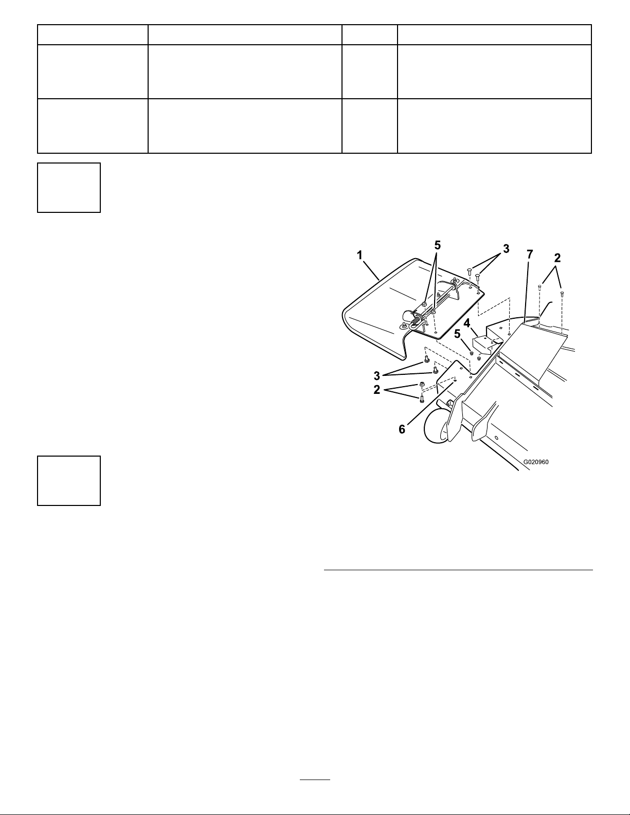
4.Removefastenerssecuringthedeectorassemblyand
existingcutoffbafetothedeck(Figure1).Retainall
fasteners.
5.For54inchmowerdecksonly,removethefasteners
pluggingtheforwardhole.(Figure1).
Installthepulleyassemblyandshoulder
bolt.
Installtheblowerassembly,baggerbelt,
spring,andplasticbeltcover.
Use
2
RemovingtheExistingBelt
CoverandtheDischarge
Chute
NoPartsRequired
Procedure
Note:Cleantheareaaroundthebeltcoverbeforeremoving
it.
1.Lowerthemowerdecktothelowestheight-of-cut
position.
2.Loosentheright-hand,belt-coverbolts(Figure1).
Note:Forthe60inchmower-deckbeltcover,the
boltswillneedtoberemoved.
3.Removetheright-handbeltcover.
Figure1
1.Deectorassembly5.Locknut(existing)
2.Fasteners(existing),retain6.Forwardhole(54inch
3.Carriagebolt(existing)
4.Cutoffbafe(existing)
6.Storetherighthandbeltcoverandthedischargechute
forlateruse.Installthemwhenthebagger,blower,
andthepulleyareremoved.
2
mowerdecksonly)
7.Beltcover
Page 3
3
3,4
1 2
g020943
1
2
3
4
g026105
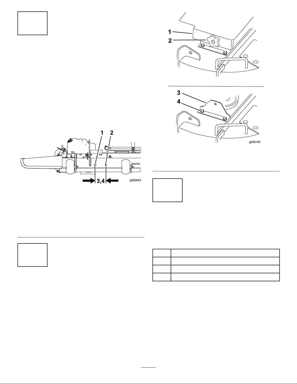
DrillingtheBafeHole
NoPartsRequired
Procedure
Certain54inchand60inchmowerdecksneedasecondhole
toinstallthebafe.UseFigure2todetermineifyouhave
thesecondhole.Ifyouhavethesecondhole,gotothenext
procedure.
1.Fromthecenterofexistingslot,measureoverthe
correctdistanceasshowninFigure2.
2.Markandcenterpunchthepositionforthenewhole.
3.Drillanew3/8inchhole.
Figure3
1.Beltcover3.Bracket
2.Knob
4.Bolts(retain)
Figure2
1.Existingslot
2.Drill3/8inchhole4.Measure1 1.43cm(4-1/2
3.Measure9.52cm(3-3/4
inches)for54inchmower
decks
inches)for60inchmower
decks
5
InstallingtheBafeand
BlowerSupportfor48inch
MowerDecks
Partsneededforthisprocedure:
1Blowersupport
1
4
RemovingtheBracketforthe
BeltCover
NoPartsRequired
Procedure
Note:Thisprocedureisforonlybeltcoverswithknobsas
showninFigure3.
1.Removetheknobandthebeltcoverfromthemower
deck(Figure3).
2.Removethebracketattachedtothemowerdeck(Figure
3).Savetheboltstomountthemetal-beltcover.
Procedure
Thisprocedureisfor48inchmowerdecksonly.
1.Alignthebafesothebafestudsgothroughthefront
2.Installthebafetothefrontofthemowerdeckwith
3.Installtheblowersupportandexistingcutoffbafe
Bafe
3
Bolt(5/16x1inch)
5
Flangenut(5/16inch)
andtopmowerdeckholes.
aangenut(5/16inch)(Figure4).
tothetopofthemowerdeckwith3bolts(5/16x1
inch)and3angenuts(5/16inch).RefertoFigure4
3
Page 4

forthecorrectpositionoftheblowersupportandthe
g021007
2
3
5
1
4
1
6
5
existingcutoffbafe.
4.Usingtheverticalstudinthebafe,installtheblower
supporttothemowerdeckwithaangenut(5/16
inch)(Figure4).
6
InstallingtheBafeand
BlowerSupportfor54inch
MowerDecks
Partsneededforthisprocedure:
1Blowersupport
1
Largebafe
1
Smallbafe
3
Bolt(5/16x1inch)
5
Flangenut(5/16inch)
Procedure
Thisprocedureisfor54inchmowerdecksonly.
1.Alignthelargebafesothebafestudsgothroughthe
frontandtopmowerdeckholes.
2.Installthelargebafetothefrontofthemowerdeck
withaangenut(5/16inch)(Figure5).
3.Installtheblowersupportandexistingcutoffbafe
tothemowerdeckwith3bolts(5/16x1inch)and
3angenuts(5/16inch).RefertoFigure5forthe
correctpositionoftheblowersupportandtheexisting
Figure4
1.Flangenut(5/16inch)4.Bafe
2.Blowersupport
3.Mowerdeck
5.Bolt(5/16x1inch)
6.Existingcutoffbafe
cutoffbafe.
4.Usingtheverticalstudinthelargebafe,installthe
bafeandblowersupportofthemowerdeckwitha
angenut(5/16inch)(Figure5).
5.Usingtheexistingnutandbolt,looselyinstallthesmall
bafetothemowerdeck(Figure5).
6.Rotatethesmallbafeuntilittouchesthelargebafe
andthefrontofthemowerdeck.
7.Tightentheexistingnutandbolt.
4
Page 5

g020963
2 3
1
4
1
5
8
7
6
7
9
5
7
InstallingtheBafeand
BlowerSupportfor60inch
MowerDecks
Partsneededforthisprocedure:
1Blowersupport
1
Bafe
1
Cutoffbafe
5
Bolt(5/16x1inch)
10
Flangenut(5/16inch)
3
Carriagebolt(5/16x3/4inch)
Procedure
Thisprocedureisfor60inchmowerdecksonly.
1.Installthecutoffbafetotheblowersupportwith2
carriagebolts(5/16x3/4inch)anda2angenuts
(5/16inch)(Figure6).
Figure5
1.Flangenut(5/16inch)6.Largebafe
2.Blowersupport7.Useexistinghardware
3.Mowerdeck
4.Ifneeded,drilla3/8inch
holehereforthebafe
5.Bolt(5/16x1inch)
8.Smallbafe
9.Existingcutoffbafe
2.Alignthelargebafesothebafestudsgothroughthe
frontandtopmowerdeckholes.
3.Installthelargebafetothefrontofthemowerdeck
withaangenut(5/16inch)(Figure6).
4.Usingtheverticalstudinthebafe,installthebafe
tothetopofthemowerdeckwithaangenut(5/16
inch)(Figure6).
Note:Ifnecessary,removetheexistinghardware.
5.Installtheblowersupporttothemowerdeckwith4
bolts(5/16x1inch)and4angenuts(5/16inch)
(Figure6).
6.Installthebafeguardtothebafewithacarriagebolt
(5/16x3/4inch)andaangenut(5/16inch)(Figure
6).
7.Installthebafeguardtothemowerdeckwithabolt
(5/16x1inch)andaangenut(5/16inch)(Figure6).
5
Page 6

1
2
3
4
5
1
1
7
8
9
9
1
6
4
g021354
8
G020961
4
InstallingthePulleyAssembly,
MetalBeltCover,andShoulder
Bolt
Partsneededforthisprocedure:
1Pulleyassembly
1
Shoulderbolt
1
Flangenut(5/16inch)
1Metalbeltcover
Procedure
1.Removethenutandwasherfromtherighthandmower
deckpulley.
2.Installthepulleyassemblytotherightmowerdeck
pulleywiththepreviouslyremovednut.Donotuse
thewasher.Savethewasheranduseitwhenthepulley
assemblyisremoved(Figure7).
3.Torquethenutto136–149N-m(100–110ft-lb).
Figure6
1.Flangenut(5/16inch)6.Ifneeded,drilla(3/8inch)
2.Blowersupport
3.Cut-offbafe8.Attachbafeguardtothe
4.Carriagebolt(5/16x3/4
inch)
5.Mowerdeck
holehereforthebafe
7.Largebafe
frontedgeofthemower
deck
9.Bolt(5/16x1inch)
1.Existingpulleynut
2.Blowerpulley
Figure7
54inchmowerdeckshown
3.Existingdeck(spindle)
pulley
4.Spindle
4.Forthemachineswithbelt-coverknobs(Figure3),
installtheboltsusedforthebracket.RefertoFigure9
tousetheboltheadsforthenewmetal-beltcover.
5.Installtheshoulderbolttotherearoftheslotinblower
assembly.Securetheshoulderboltwithaangenut
(5/16inch).
6
Page 7

g020773
1
2
3
1.Blowerassembly
1
2
3
g021338
2.Flangenut(5/16inch)
Figure8
3.Shoulderbolt
9
InstallingtheBlower
Assembly,BaggerBelt,
Spring,andPlasticBeltCover
Partsneededforthisprocedure:
1Blowerassembly
1Baggerbelt
1
Spring
1Plasticbeltcover
6.Installthemetalbeltcoverovertheexistingboltheads
onthemowerdeck.
7.Slidethemetalbeltcoverforwardsothefronttabsare
intheslotsandtheboltheadsslideintothekeyslots
(Figure9).
Figure9
1.Metal-beltcover3.Fronttabsslideintoslots
2.Boltheads
Procedure
RefertotheBaggerOperator’sManualforthecorrectprocedure
toinstalltheblowerassembly ,baggerbelt,spring,andbelt
covers.
7
Page 8

 Loading...