

Page 1

FormNo.3367-329RevA
32inBagger
2011andAfterTimeCutter
®
Z3000Series
RidingMower
ModelNo.79333—SerialNo.311000001andUp
ToregisteryourproductordownloadanOperator'sManualorPartsCatalogatnocharge,gotowww.T oro.com.OriginalInstructions(EN)
Page 2
Introduction
Readthisinformationcarefullytolearnhowtooperate
andmaintainyourproductproperlyandtoavoidinjury
andproductdamage.Youareresponsibleforoperating
theproductproperlyandsafely.
Thismanualuses2otherwordstohighlightinformation.
Importantcallsattentiontospecialmechanical
informationandNoteemphasizesgeneralinformation
worthyofspecialattention.
Contents
YoumaycontactTorodirectlyatwww .Toro.comfor
productandaccessoryinformation,helpndinga
dealer,ortoregisteryourproduct.
Wheneveryouneedservice,genuineT oroparts,or
additionalinformation,contactanAuthorizedService
DealerorToroCustomerServiceandhavethemodel
andserialnumbersofyourproductready.
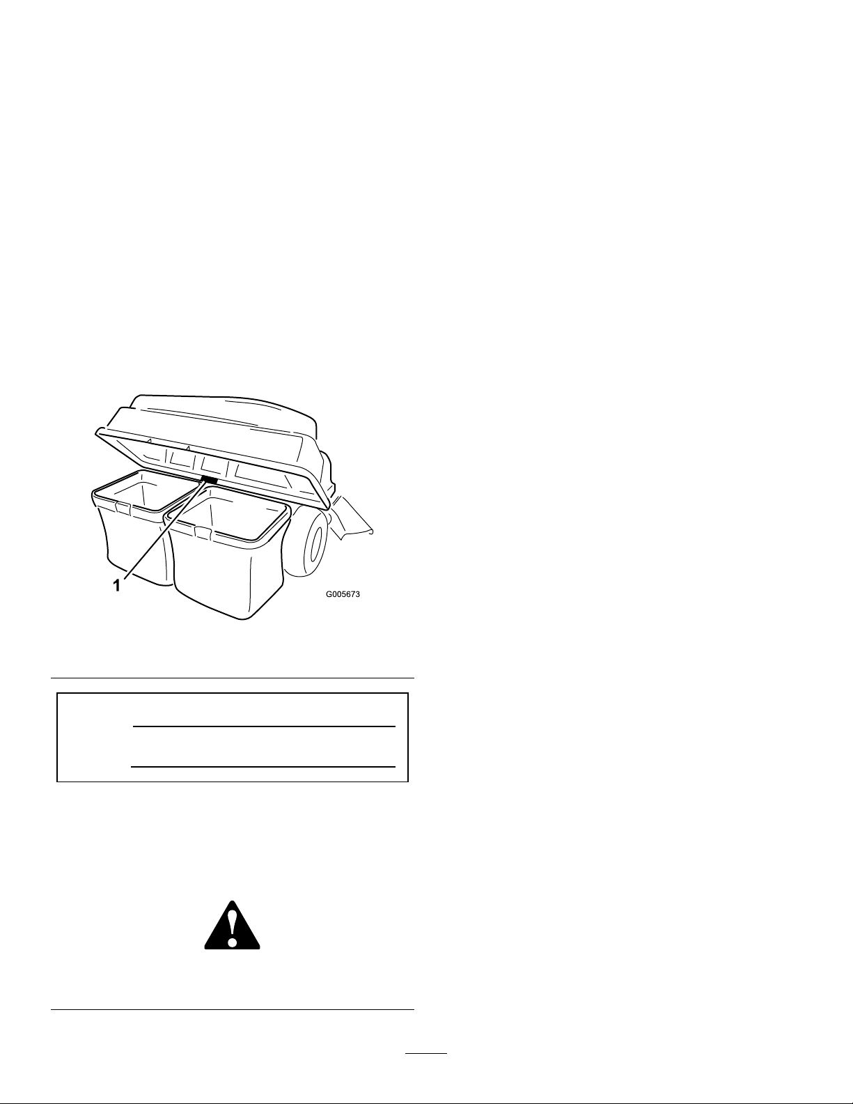
Figure1
identiesthelocationofthemodelandserialnumbers
ontheproduct.Writethenumbersinthespace
provided.
Figure1
1.Modelandserialnumberlocation
Introduction.................................................................2
Safety...........................................................................3
TowingSafety.......................................................3
SafetyandInstructionalDecals.............................4
Setup............................................................................5
1InstallingtheW eight..........................................6
2InstallingtheRearGuard...................................8
3InstallingtheBaggerFrame................................8
4AssemblingtheBaggerT op..............................10
5InstallingtheBaggerTop.................................10
6InstallingtheChute..........................................11
7ConnectingwiththeDischargeTube................13
8InstallingtheDeckRing...................................13
9InstallingtheBlade..........................................14
Operation...................................................................14
EmptyingtheGrassBags....................................14
ClearingObstructionsfromtheBagger...............15
RemovingtheBagger.........................................15
OperatingTips...................................................15
Maintenance...............................................................17
RecommendedMaintenanceSchedule(s)................17
InspectingtheBaggerAttachment......................17
InspectingtheMowerBlades..............................17
CaringfortheGrassBags...................................18
CleaningtheBaggerAttachment.........................18
Storage.......................................................................18
StoringtheBaggerAttachment...........................18
ModelNo.
SerialNo.
Thismanualidentiespotentialhazardsandhas
safetymessagesidentiedbythesafetyalertsymbol
(Figure2),whichsignalsahazardthatmaycauseserious
injuryordeathifyoudonotfollowtherecommended
precautions.
Figure2
1.Safetyalertsymbol
©2010—TheT oro®Company
8111LyndaleAvenueSouth
Bloomington,MN55420
Contactusatwww.T oro.com.
2
PrintedintheUSA.
AllRightsReserved
Page 3

Safety
DANGER
Enginescanbecomehotwhentheyareoperating.
Severeburnscanoccurfromcontactinghot
surfaces.
Allowengines,especiallythemufer,tocoolbefore
touching.
DANGER
Debris,suchasleaves,grass,orbrushcancatch
re.Areintheengineareacancausepersonal
injuryandpropertydamage.
TowingSafety
•Donotattachtowedequipmentexceptatthehitch
point.
•Followtheattachmentmanufacturer’s
recommendationforweightlimitsfortowed
equipmentandtowingonslopes.
•Neverallowchildrenorothersinorontowed
equipment.
•Onslopes,theweightofthetowedequipmentmay
causelossoftractionandlossofcontrol.Reduce
towedweightandslowdown.
•Stoppingdistanceincreaseswiththeweightofthe
towedload.Travelslowlyandallowextradistance
tostop.
•Keeptheengineandmuferareafreeofdebris
accumulation.
•Takecarewhenopeningthebaggercoverto
keepdebrisfromfallingontotheengineand
muferarea.
•Allowthemachinetocoolbeforestoringit.
•Makewideturnstokeeptheattachmentclearofthe
machine.
•Donottowaloadthatweighsmorethanthetowing
machine.
3
Page 4

SafetyandInstructionalDecals
Safetydecalsandinstructionsareeasilyvisibletotheoperatorandarelocatednearanyareaof
potentialdanger.Replaceanydecalthatisdamagedorlost.
109-6809
1.Crushinghazardofhand—donotremovethewholebaggerfromthemachine;openthebaggertopandthenremovethebag(s)
fromthebagger.Donotremovethebaggertopwhenitisclosed;openthebaggertopandthenremoveit.
109-7076
4
Page 5

Setup
LooseParts
Usethechartbelowtoverifythatallpartshavebeenshipped.
ProcedureDescription
1
2
3
4
5
6
Bolt(3/8x1-1/4inches)
Locknut(3/8inch)
Weightmountingbracket,left
Weightmountingbracket,right1
Washers4
Weightholdingbracket1
Bolt(3/8x1inch)
Flatweight1
Suitcaseweight
Keyedcrossbar1
Rearguard1
Selftappingscrew(5/16x3/4inch)
Baggerframesupportbracket
Supportspacerplate
Selftappingscrew(5/16x3/4inch)
Bolt(5/16x1inch)
Locknut(5/16inch)
Angledbracket1
Carriagebolt(5/16x3/4inch)
Baggerframe
Clevispin(1/2x2-1/4inch)
Hairpincotter
Rod2
Washer4
Baggertop1
Baggerscreen1
GrassBag
Upperbaggertube1
Cutoffbafe
Chute
Qty.
Use
4
4
1
Installtheweight.
2
1
4
1
1
2
2
4
2
1
1
5
2
1
1
Installtherearguard.
Installthebaggerframe.
Assemblethebaggertop.
Installthebaggertop.
Installthechute.
7
8
9
Nopartsrequired
Deckring4
Bolt(5/16x3/4inch)
Locknut(5/16inch)
Hi-Liftblade
5
–
8
8
1Installtheblade.
Connectwiththedischargetube.
Installthedeckring
Page 6
1
G014875
1
2
3
4
G014877
1
2
3
4
InstallingtheWeight
Partsneededforthisprocedure:
4
Bolt(3/8x1-1/4inches)
4
Locknut(3/8inch)
1
Weightmountingbracket,left
1Weightmountingbracket,right
4Washers
1Weightholdingbracket
2
Bolt(3/8x1inch)
1Flatweight
1
Suitcaseweight
1Keyedcrossbar
Procedure
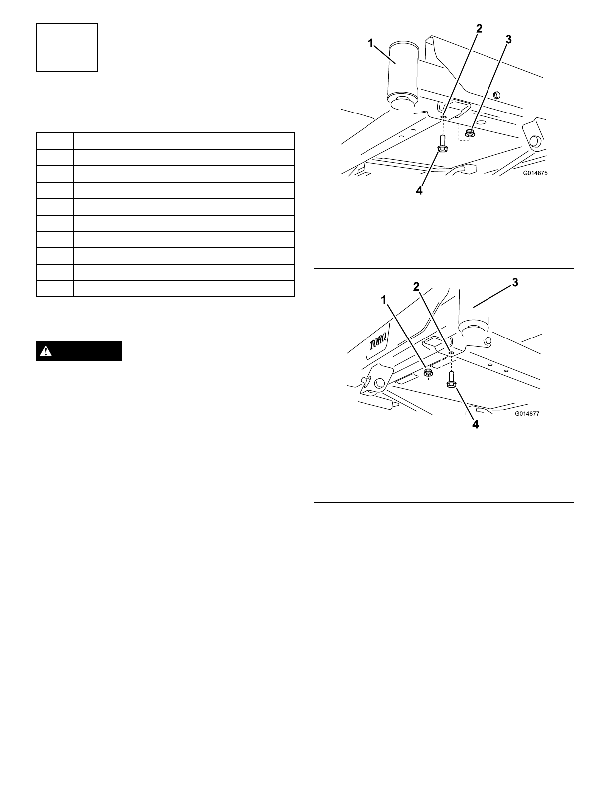
1.Frontrightcaster(castor
forkandwheelnotshown
forclarity)
2.Forwardhole,rightside
Figure3
3.Bolt(3/8x1inch)
4.Locknut(3/8inch)
CAUTION
Thebaggerchangestheweightdistributionofthe
machine.Operatingthemachinewithoutthefront
weightsmaycauseanunstableconditionwhich
couldresultinalossofcontrol.
Ensurethefrontweightsareproperlyinstalled
beforeoperatingthemachinewiththebagger
attachment.
1.Locatetheforwardboltsontheundersideofthe
frame(Figure3andFigure4).Removethetwobolts
(3/8x1inch)andtwolocknuts(3/8inch).Retain
thelocknuts.
Figure4
1.Locknut(3/8inch)3.Frontleftcaster(castor
2.Forwardhole,leftside4.Bolt(3/8x1inch)
forkandwheelnotshown
forclarity)
2.Locatetheleftandrightweightmountingbrackets
inlooseparts.Startbyinstallingtheleftbracketto
theundersideoftheframe.
3.Securethebrackettotheframeusingtwobolts(3/8
x1-1/4inches),twowashersandtwolocknuts(3/8
Figure5).Onelocknutisfromloosepartsand
inch)(
theotherisreusedfromearlierremoval.
6
Page 7

G014878
1
2
3
4
5
6
7
8
Figure5
G014876
1
2
3
4
5
6
7
8
G014883
1
2
3
4
5
6
7
8
G014879
1
2
3
4
5
1.Locknut(3/8inch),existing5.Hole,existinginframe
2.Forwardhole,leftside
3.Frontleftcaster(castor
forkandwheelnotshown
forclarity)
4.Locknut(3/8inch),loose
parts
6.Washer
7.Bolt(3/8x1-1/4inches)
8.Leftmountingbracket
4.Ontherightsideofthemachineinstalltheright
weightmountingbracket.
•Formachineswithoutafootassistliftpedal:
securethebracketusingtwobolts(3/8x1-1/4
inches),twowashersandtwolocknuts(3/8
Figure6).Onelocknutisfromlooseparts
inch)(
andtheotherisreusedfromearlierremoval.
theforwardfastenersinthefootassistliftpedal
bracket.Securethebracketusingtwoboltsand
twolocknuts(
Figure7).Onelocknutisfrom
loosepartsandtheotherisreusedfromearlier
removal.
Figure7
1.Frontrightcaster(castor
forkandwheelnotshown
forclarity)
2.Forwardhole,rightside
3.Locknut(3/8inch),existing
4.Rightmountingbracket
5.Bolt(3/8x1-1/4inches)
6.Footassistliftpedal
bracket
7.Hole,existinginbracket
8.Locknut(3/8inch),loose
parts
5.Installtheweightholdingbrackettothemounting
brackets(Figure8).Aligntheinboardholesin
thebracketwiththemountingbracketsinstalled
previously.Makesurethebracketiscenteredonthe
frame.Securewithtwobolts(3/8x1inch)andtwo
locknuts(3/8inch).
Figure6
1.Frontrightcaster(castor
2.Forwardhole,rightside6.Washer
3.Locknut(3/8inch),existing7.Hole,existinginframe
4.Rightmountingbracket
forkandwheelnotshown
forclarity)
•Formachineswithafootassistliftpedal:The
washerswillnotbeneeded.Instead,remove
5.Bolt(3/8x1-1/4inches)
8.Locknut(3/8inch),loose
parts
Figure8
1.Locknut(3/8inch)4.Bolt(3/8x1inch)
2.Weightholdingbracket5.Rightmountingbracket
3.Leftmountingbracket
7
Page 8
6.Installaatweighttotheholdingbracketandmove
G014880
1
2
3
G015328
1
2
3
4
itrearward,ushwiththebracket(Figure9).
2
InstallingtheRearGuard
Partsneededforthisprocedure:
1Rearguard
4
Selftappingscrew(5/16x3/4inch)
Procedure
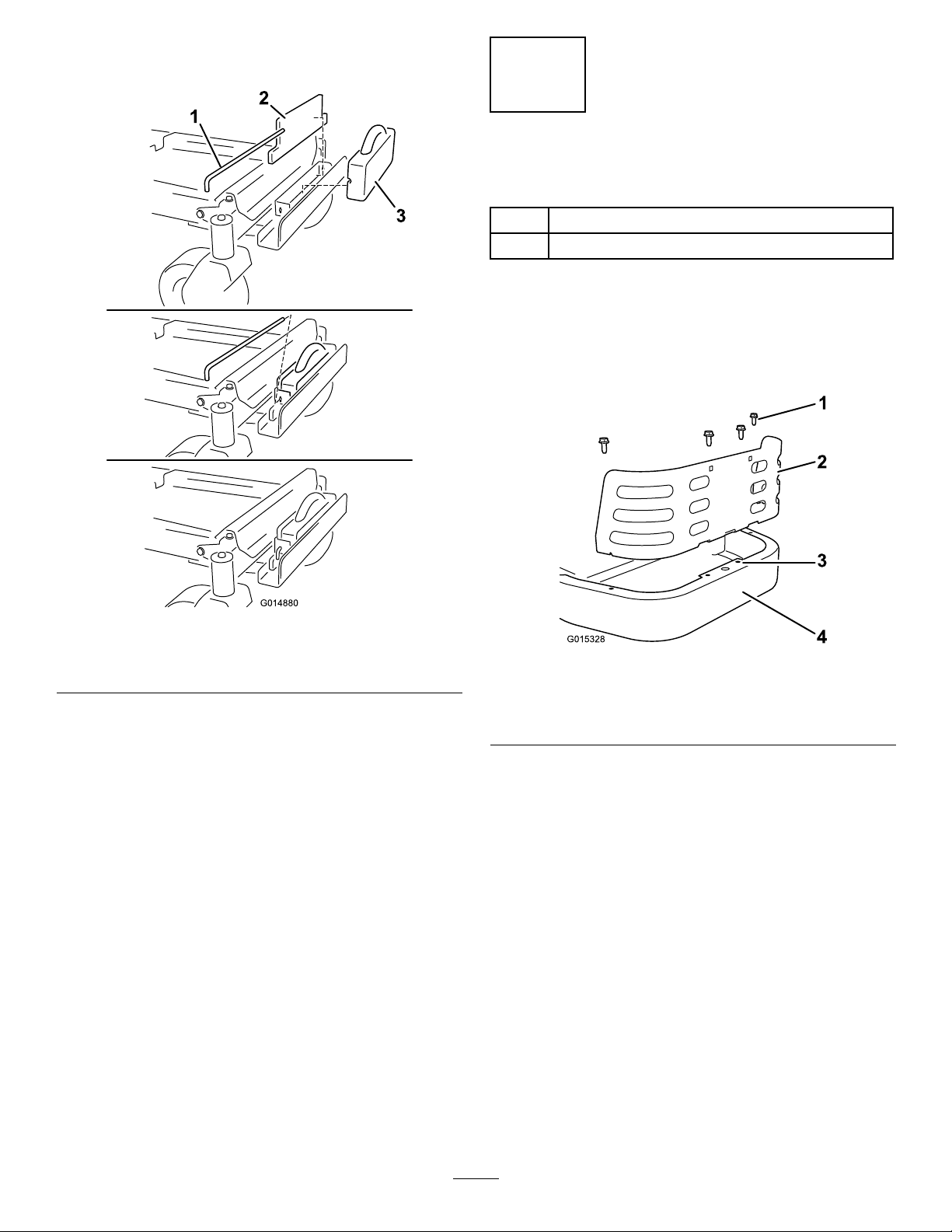
1.Installtherearguardtotheframebehindtheengine
Figure10).Aligntheholesinthetabsontheguard
(
withtheexistingholesintherearframe.
Figure9
1.Flatweight3.Keyedcrossbar
2.Suitcaseweight
7.Installasuitcaseweightinfrontoftheatweight
(Figure9).Thegrooveinthesuitcaseweightshould
befacingrearward.
8.Securetheweightstothebracketwithakeyedcross
Figure9).Installthebarandrotateit90degrees
bar(
downwardtolockitinplace.
9.Onceallweightsandbracketshavebeeninstalled,go
backandcheckthatallfastenersaretight.Tighten
asnecessary.
Important:Wheneveryouremovethebagger
attachment,remembertoremovethefrontweights
toreturntheproperstabilitytothemachine.
Figure10
1.Selftappingscrew(5/16x
3/4inch)
2.Rearguard
3.Holeinrearframe,
exisiting
4.Rearframe
2.Securetheguardtotheframewithfourselftapping
screws(5/16x3/4inch)asshowninFigure10.
8
Page 9

3
G014881
1
2
3
4
5
6
1
2
G010578
G014882
1
2
3
4
InstallingtheBaggerFrame
Partsneededforthisprocedure:
1
Baggerframesupportbracket
1
Supportspacerplate
2
Selftappingscrew(5/16x3/4inch)
2
Bolt(5/16x1inch)
4
Locknut(5/16inch)
1Angledbracket
2
Carriagebolt(5/16x3/4inch)
1
Baggerframe
1
Clevispin(1/2x2-1/4inch)
5
Hairpincotter
2Rod
4Washer
Figure12
1.Supportbracket2.Selftappingscrews(5/16
x3/4inch)
3.Installtheangledbaggerbrackettotheengineguard
usingtwocarriagebolts(5/16x3/4inch)andtwo
locknuts(5/16inch).
Procedure
1.Locatethebaggerframesupportspacerplateand
bracketinlooseparts.Installtheplateandbracketto
themachineframeasshowninFigure11.Securethe
plateandbrackettotheframeusingtwobolts(5/16
x1inch)andtwolocknuts(5/16inch).
Figure11
1.Machineframe4.Bolt(5/16x2-1/2inch)
2.Supportspacerplate
3.Supportbracket6.Locknut(5/16inch)
5.Drawbarhole
2.Securethesupportbrackettothebottomofthe
machineframefrombelowusingtwoselftapping
screws(5/16x3/4inch)asshowninFigure12.
Figure13
1.Carriagebolt(5/16x3/4
inch)
2.Angledbracket4.Holeinengineguard,
3.Locknut(5/16inch)
existing
4.Installthebaggerframetothesupportbracket.
Securethebaggerframewithaclevispin(1/2x
2-1/4inch)andhairpincotter(
Figure13).
9
Page 10
G014884
1
2
3
4
5
Figure14
G014885
1
2
3
4
5
6
G005666
1
2
3
4
1.Baggerframe(60inch
decks)
2.Clevispin(1/2x2-1/4
inch)
3.Supportbracket,receiver
4.Hairpin
5.Anglebracket
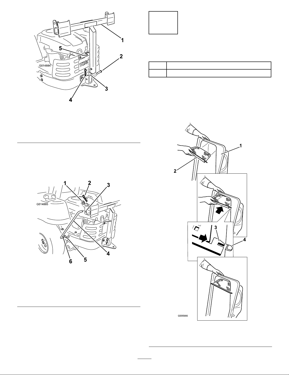
5.Installtwosupportrods,onetoeachsideofthe
baggerframe.Locatetheexistingkeyedslotinthe
machineframeandinstallthebent,aredendofthe
rodintothatslot(Figure15).Movetherodrearward
toseatitintheframe.
4
AssemblingtheBaggerTop
Partsneededforthisprocedure:
1Baggertop
1Baggerscreen
Procedure
Turnthebaggertopover.Installthescreenasshown
in
Figure16soitslopesdowntowardthecollection
bags.Makesurethescreenssnapintoplaceandthetabs
engagethebaggertop.
Figure15
Leftsideshown
1.Washer
2.Hairpin5.Keyedslot,existing
3.Bracketframehole6.Bent,aredendofsupport
6.Insertthebentendsoftherodintothebaggerframe
asshowninFigure15.Securetheendoftherod
withawasherandhairpin.
4.Supportrod
rod
Figure16
1.Baggertop
2.Screen4.Slotinbaggertop
3.Screentab
10
Page 11
5
G014888
1
2
3
4
5
6
G005672
1
2
3
4
G005757
InstallingtheBaggerTop
Partsneededforthisprocedure:
2
GrassBag
1Upperbaggertube
Procedure
1.Installthebaggertoptothebaggerframe.Rotate
thebaggertoptoalignthekeyholesinthebagger
topbracketswiththekeysinthepostsonthebagger
frame(
androtatethebaggertopdowntotheoperating
position.
Note:Thebaggertopiseasiertoinstalliftwo
peopleworktogether.
Figure17).Slidethebracketsovertheposts
2.Liftthebaggertopandinstallthebagsbysliding
thebagframehooksontotheretainingbrackets
(Figure18).
Figure18
1.Bag3.Retainingbracket
2.Baggerframe4.Bagframehook
3.Lowerthebaggertopontothebag(Figure19).
Figure19
Figure17
1.Baggertop4.Bracket,baggertop
2.Baggerframe
3.Keyhole6.Post
5.Key
4.Installtheupperbaggertube.Insertthecurvedend
intotheopeninginthebaggertop.Makesurethe
aredendwiththeretentionpostispointingdown
andfrowardinpreparationtobematedwiththe
FinishingKit.
11
Page 12

6
G015220
1
2
3
4
5
G015221
1
2
3
4
5
G015222
1
2
3
4
InstallingtheChute
Partsneededforthisprocedure:
1
Cutoffbafe
1
Chute
Procedure
1.Liftupthegrassdeectorandlocatetheexisting
cutoffbafe.
2.Removethelocknutsandboltsecuringthecutoff
bafetotheundersideofthedeck(Figure20).
Retainallfasteners.
Figure21
1.Pivotrod
2.Bolt5.Locknut
3.Cutoffbafe(bagger)
4.Nut(5/16inch)
4.Locatethechuteinlooseparts.Aligntheholesin
thehingeonthechutewiththehingeonthedeck
(Figure22).Securethechutetothedeckusingthe
hairpinonthelanyardconnectedtothechute.
Figure20
1.Pivotrod
2.Bolt5.Locknut
3.Cutoffbafe(existing)
3.Installthenewcutoffbafetotheundersideof
thedeck(Figure21).Secureitwiththefasteners
removedpreviously.
4.Nut(5/16inch)
Figure22
1.Chute
2.Lanyardhairpin4.Hinge,onchute
3.Hinge,ondeck
5.Pivotthechutebackandtowardthedecksochuteis
ushwiththemowerdeck.
Note:Asthechutemateswiththedeck,makesure
theupperlatchisoutofthewayofthepivotrod.
6.Onthetopofthechute,engagetheupperlatch
aroundpivotrodofthedeectorassemblyasshown
12
inFigure23.
Page 13

G015223
1
2
Figure23
G010641
1
2
3
4
5
1.Upperlatch2.Flexiblelatch
7.Securethechutetothedeck.Hooktheexiblelatch
onthechutetotheretainingclaspweldedonthe
mowerdecktotherearoftheopening(Figure23).
7
ConnectingwiththeDischarge
Tube
NoPartsRequired
Figure24
1.Dischargetube,curved
end
2.Openinginbaggertop
3.Dischargetube,aredend
2.Slidethearedendofthedischargetubeoverthe
endofthechute.Movetherubberretainingstrapon
thechutesnapsoverthepegonthedischargetube
tosecureit(Figure24).
4.Peg
5.Rubberstrap
Procedure
1.Slidethecurvedendofthedischargetubeintothe
openinginthebaggertop(Figure24).
8
InstallingtheDeckRing
Partsneededforthisprocedure:
4Deckring
8
Bolt(5/16x3/4inch)
8
Locknut(5/16inch)
Procedure
1.Installtheinterlockingdeckringstothebottomof
themower(Figure25).
13
Page 14

G015226
1
2
3
Operation
G005758
Note:Determinetheleftandrightsidesofthe
machinefromthenormaloperatingposition.
WARNING
Toavoidpersonalinjury,followtheseprocedures:
•Becomefamiliarwithalloperatingandsafety
instructionsinthe
mowerbeforeusingthisattachment.
•Neverremovethedischargetube,bags,bagger
top,orthechutewhiletheengineisrunning.
Operator’ s Man ual
forthe
Figure25
1.Locknut(5/16inch)
2.Bolt(5/16x3/4inch)
2.Securetheringstothedeckusing8bolts(5/16x
3/4inch)and8locknuts(5/16inch).
3.Deckring
9
InstallingtheBlade
Partsneededforthisprocedure:
1
Hi-Liftblade
Procedure
1.Removetheexistingmowerbladeinstalledonyour
deck.RefertotheRemovingtheBladessectionin
theOperator’sManualformoreinformation.
•Alwaysshuttheengineoffandwaitforall
movingpartstostopbeforeclearingan
obstructionfromthebaggingsystem.
•Neverdomaintenanceorrepairswhilethe
engineisrunning.
EmptyingtheGrassBags
Becarefulwhenliftingorhandlingagrassbagthatis
full.Toemptythegrassbags:
1.Parkthemachineonalevelsurfaceanddisengage
thebladecontrolswitch.
2.Movethemotioncontrolleversoutwardtothe
neutrallockposition,stoptheengine,removethe
key,settheparkingbrakeandwaitforallmoving
partstostopbeforeleavingtheoperatingposition.
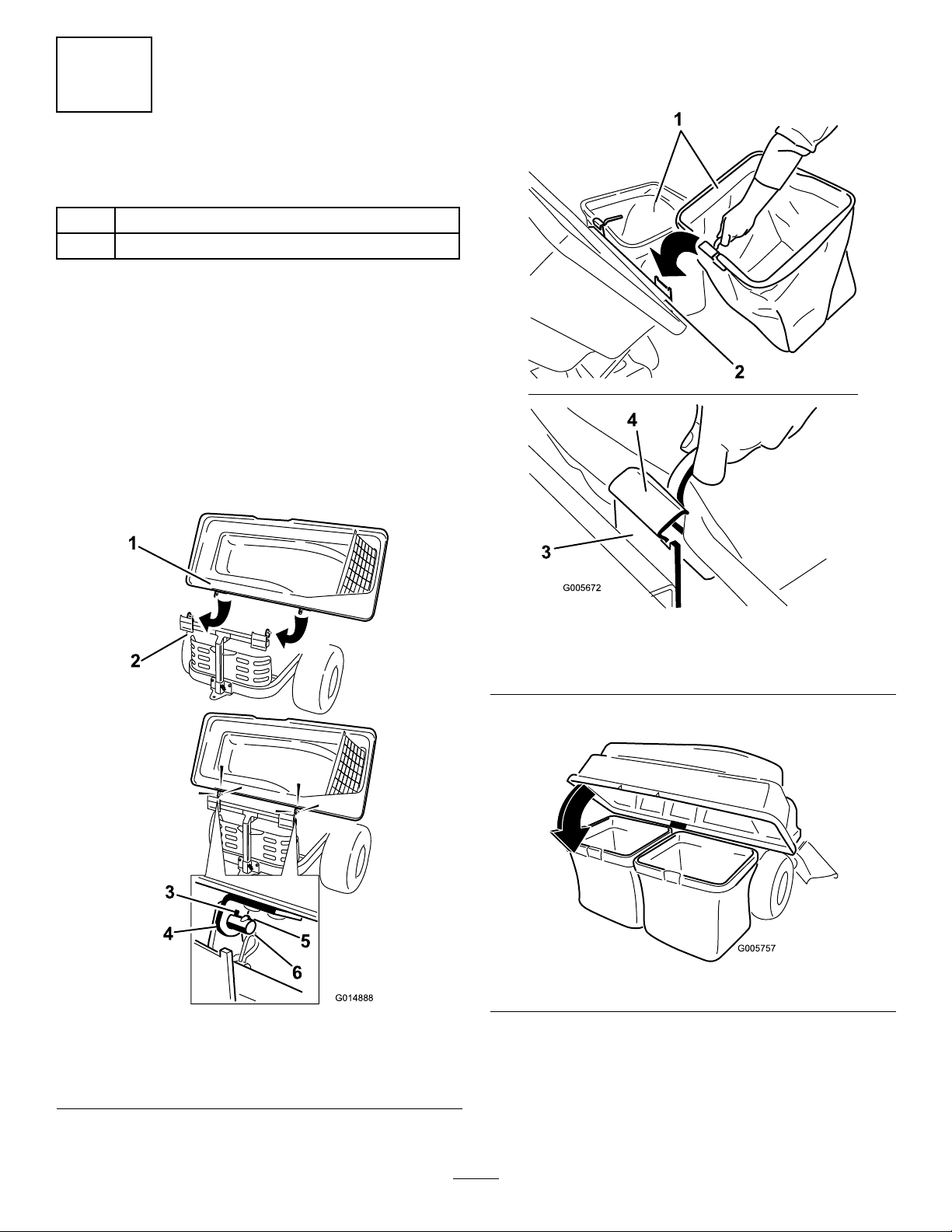
3.Open(raise)thebaggertop(
Figure26).
2.InstalltheHi-Liftmowerbladelocatedinloose
parts.RefertotheInstallingtheBladessectioninthe
Operator’sManualformoreinformation.
Figure26
4.Compressdebrisintothebags.Withbothhands,
liftuponthebagandunhookitfromtheretaining
bracket.Emptythebag.Repeattheprocedurefor
theotherbag.
5.Installthebagsbyslidingthebagframehooksonto
theretainingbrackets(Figure27).
14
Page 15
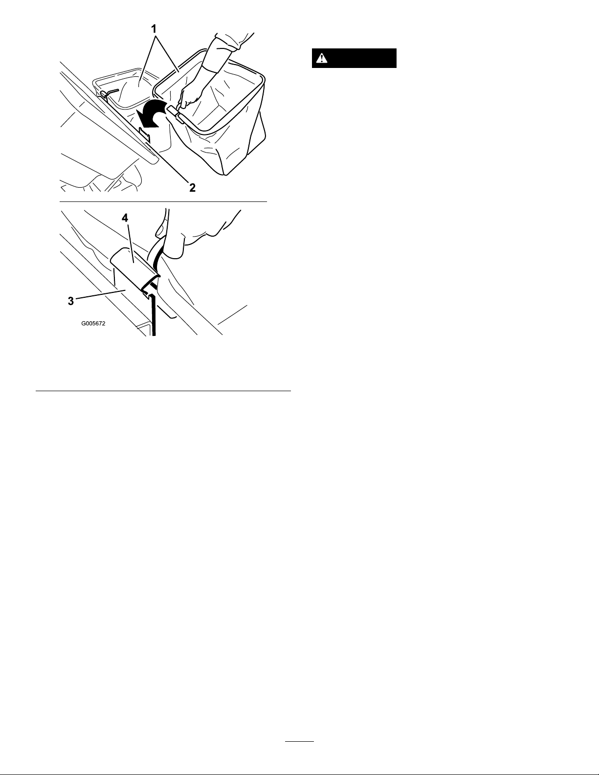
G005672
1
2
3
4
RemovingtheBagger
CAUTION
Failingtoremovethefrontbaggerweights
andoperatingthemachinewithoutthebagger
attachmentmaycauseanunstableconditionwhich
couldresultinalossofcontrol.
•Alwaysremovethefrontweightswhen
removingthebaggerattachment.
•Neveroperatethemachinewithoutthebagger
attachmentandthefrontweightsstillinstalled.
ThebaggercanberemovedbyrepeatingtheSetup
sectionsfromallinstalledbaggerrelatedkitsinreverse
order.Ifweightsareinstalled,alwaysremovethefront
baggerweightswhenremovingthebaggerattachments.
Note:Itisonlynecessarytoremovethecutoffbafe
wheninstallingamulchingkit.
OperatingTips
Figure27
1.Bag3.Retainingbracket
2.Baggerframe4.Bagframehook
6.Lowerthebaggertopontothebags.
ClearingObstructionsfrom
theBagger
1.Parkthemachineonalevelsurfaceanddisengage
thebladecontrolswitch.
2.Movethemotioncontrolleversoutwardtothe
neutrallockposition,stoptheengine,removethe
key,settheparkingbrakeandwaitforallmoving
partstostopbeforeleavingtheoperatingposition.
3.Checkthegrassbagsandemptythemiftheyarefull.
4.Removeandseparatethedischargetubeandchute
fromthebaggertopandmower.Usingastick
orsimilarobject,carefullyremoveandclearthe
obstructionfromthemower,dischargetube,chute,
andthebaggertop.
5.Afteryouremovetheobstruction,installthe
completebaggersystemandresumeoperation.
TipsforBagging
Size
Rememberthatthemowerislongerandwiderwiththis
attachmentinstalled.Byturningtoosharplyinconned
placesyoumaydamagetheattachment.
Trimming
Alwaystrimwiththeleftsideofthemower.Donot
trimwiththerightsideofthemowerbecauseyoucould
damagethebagger’schuteanddischargetube.
CuttingHeight
Donotsetthemowercuttingheighttoolowbecause
longgrasssurroundingthemowercanpreventairfrom
gettingunderthemowerandenteringthebagging
system.Ifenoughairdoesn’tgetunderthemower,the
baggingsystemwillplug.
CuttingFrequency
Cutthegrassoften,especiallywhenitgrowsrapidly.
Youwillhavetocutyourgrasstwiceifitgetsexcessively
long.
CuttingTechnique
Forbestlawnappearance,besuretoslightlyoverlap
themowerintothepreviouslycutarea.Thishelps
15
Page 16

reducetheloadontheengineandreducesthechance
ofpluggingthechuteanddischargetube.
BaggingSpeed
Mostoftenyouwillbagwiththemowerthrottlein
theFastpositionanddriveatanormalgroundspeed.
However,inextremelydryanddustygrass,youmay
wanttoslightlyreducethethrottlespeedandincrease
thegroundspeedofthemower.Thebaggingsystem
mayplugifyoudrivetoofastandtheenginespeed
getstooslow.Onhillsitmaybenecessarytoslowthe
mowergroundspeed.Thishelpsmaintaintheengine
speedandbaggingefciency.Mowdownhillwhenever
possible.
CAUTION
Asthebaggerlls,extraweightisaddedtothe
backofthemachine.Ifyoustopandstartsuddenly
onhills,youmaylosesteeringcontrolorthe
machinemaytip.
•Donotstartorstopsuddenlywhengoinguphill
ordownhill.Avoiduphillstarts.
•Ifyoudostopthemachinewhengoinguphill,
disengagethebladecontrol.Thenbackdown
thehillusingaslowspeed.
•Donotchangespeedsorstoponslopes.
•Neveroperatethemachinewithoutthebagger
attachmentandthefrontweightsstillinstalled.
BaggingLongGrass
BaggingLongGrassExcessivelylonggrassisheavyand
maynotbepropelledcompletelyintothegrassbags.If
thishappens,thedischargetubeandchutemayplug.
Toavoidpluggingthebaggingsystem,mowthegrass
atahighheightofcut,thenlowerthemowertoyour
normalcuttingheightandrepeatthebaggingprocess.
BaggingWetGrass
Alwaystrytocutgrasswhenitisdrybecauseyour
lawnwillhaveaneatappearance.Ifyoumustcutwet
grass,usetheconventionalsidedischargefeatureofthe
mower.Severalhourslater,whentheclippingsaredry,
installthecompletebaggerattachmentandvacuumup
thegrassclippings.
SignsofPlugging
Asyouarebagging,asmallamountofgrassclippings
normallyblowoutthefrontofthemower.Anexcessive
amountofclippingsblowingoutindicatesthatthebags
arefullorthesystemisplugged.
16
Page 17

Maintenance
Note:Determinetheleftandrightsidesofthemachinefromthenormaloperatingposition.
RecommendedMaintenanceSchedule(s)
MaintenanceService
Interval
Aftertherst10hours
Beforeeachuseordaily
Beforestorage
MaintenanceProcedure
•Inspectthebagger
•Cleanthebagger
•Inspectthebagger
•Cleanthebagger
CAUTION
Ifyouleavethekeyintheignitionswitch,someonecouldaccidentlystarttheengineandseriouslyinjure
youorotherbystanders.
Removethekeyfromtheignitionanddisconnectthewirefromthesparkplugbeforeyoudoany
maintenance.Setthewireasidesothatitdoesnotaccidentallycontactthesparkplug.
DANGER
Enginescanbecomehotwhentheyareoperating.Severeburnscanoccurfromcontactinghotsurfaces.
Allowengines,especiallythemufer,tocoolbeforetouching.
DANGER
Debris,suchasleaves,grass,orbrushcancatchre.Areintheengineareacancausepersonalinjury
andpropertydamage.
•Keeptheengineandmuferareafreeofdebrisaccumulation.
•Takecarewhenopeningthebaggercovertokeepdebrisfromfallingontotheengineandmuferarea.
•Allowthemachinetocoolbeforestoringit.
InspectingtheBagger
Attachment
ServiceInterval:Aftertherst10hours
Beforestorage
Inspectthebaggerattachmentaftertherst10hoursof
operation,andmonthlythereafter.
1.Checkthechute,dischargetube,andthebaggertop.
Replacethesepartsiftheyarecrackedorbroken.
2.Tightenallnuts,bolts,andscrews.
3.Inspectallfastenersandlatches;replaceanymissing
ordamaged.
4.Inspectthegrassbagsfordeterioration.
InspectingtheMowerBlades
Inspectthemowerbladesregularlyandwhenevera
bladestrikesaforeignobject.
WARNING
Youorbystanderscouldbeseverelyinjuredby
yingdebrisorthrownobjectsthatmaypass
throughtorn,worn,ordeterioratedgrassbags.
•Checkthegrassbagsforholes,rips,wear,
andotherdeterioration.
•Donotwashthegrassbags.
•Ifthebaghasdeteriorated,installnewgrass
bagssuppliedbythemanufacturerofthis
baggerattachment.
17
Page 18

Ifthebladesarebadlywornordamaged,installnew
blades.RefertoyourmowerormowerOperator’ sManual
forcompleteblademaintenance.
Storage
StoringtheBaggerAttachment
CaringfortheGrassBags
Washingthegrassbagsisnotrecommended.
Topreventrapiddeteriorationofthebagmaterial,store
thebagswheretheywilldrycompletelyaftereachuse.
CleaningtheBagger
Attachment
ServiceInterval:Beforeeachuseordaily
Beforestorage
1.Aftereachuse,removeandwashtheinsideand
outsideofthebaggertop,dischargetube,chute,and
theundersideofthemower,usingwatersprayed
fromagardenhose.Useamilddetergenttoremove
stubborndirt.
2.Makesureyouremovemattedgrassfromallparts.
3.Flushthegrassbagswithwaterusinggardenhoseto
removeanydebris.
1.Cleanthebaggerattachment;refertoCleaningthe
BaggerAttachment.
2.Inspectthebaggerattachmentfordamage;referto
InspectingtheBaggerAttachment.
3.Makesurethegrassbagsareemptyandthoroughly
dry.
4.Storethebaggerinaclean,dryplace,outofdirect
sunlight.Thisprotectstheplasticpartsandextends
thelifeofthebagger.Ifyoumuststorethebagger
outside,coveritwithaweatherproofcover.
4.Afterwashing,letallofthepartsdrythoroughly.
18
Page 19

Notes:
19
Page 20

TheToroTotalCoverageGuarantee
AThree-Y earLimitedWarranty
TITANMowers
ConditionsandProductsCovered
TheT oro®Companyanditsafliate,ToroWarrantyCompany ,pursuantto
anagreementbetweenthem,jointlypromisetorepairanyT oroProduct,if
defectiveinmaterialsorworkmanshipfortheperiodlistedbelow .
ThisWarrantyappliestoallTITANMowersandtheiraccessories.
Thiswarrantycoversthecostofpartsandlabor,butyoumustpay
transportationcosts.
Thefollowingtimeperiodsapplyfromthedateofpurchase:
ProductsWarrantyPeriod
TITANMowers
-Frame
-Engine
Attachments(foraboveunits)3yearsor240hours*
Batteries1year
Warrantymaybedeniedifthehourmeterisdisconnected,altered,or
showssignsofbeingtamperedwith.
3yearsor240hours*
Lifetime(originalowneronly)**
3yearsor240hours*
OwnerResponsibilities
YoumustmaintainyourT oroProductbyfollowingthemaintenance
proceduresdescribedintheOperator’sManual.Suchroutine
maintenance,whetherperformedbyadealerorbyyou,isatyourexpense.
ItemsandConditionsNotCovered
Thereisnootherexpresswarrantyexceptforspecialemissionsystem
coverageandenginewarrantycoverageonsomeproducts.Thisexpress
warrantydoesnotcoverthefollowing:
•Costofregularmaintenanceserviceorparts,suchaslters,fuel,
lubricants,oilchanges,sparkplugs,airlters,bladesharpening/worn
bladeonmowers,cable/linkageadjustments,orbrakeandclutch
adjustments
•Componentsfailingduetonormalweararenotcoveredbythis
warranty
•Anyproductorpartwhichhasbeenalteredormisusedandrequires
replacementorrepairduetoaccidentsorlackofpropermaintenance
•Repairsnecessaryduetoimproperbatterycare,failuretousefresh
fuel(lessthanonemonthold),orfailuretoproperlypreparetheunit
priortoanyperiodofnon-useoveronemonth
•Pickupanddeliverycharges
•Operationalmisuse,neglect,oraccidents
•RepairsorattemptedrepairsbyanyoneotherthananAuthorized
ToroServiceDealer
InstructionsforObtainingWarrantyService
IfyouthinkthatyourT oroProductcontainsadefectinmaterialsor
workmanship,followthisprocedure:
1.ContactanyAuthorizedT oroServiceDealertoarrangeserviceattheir
dealership.Tolocateadealerconvenienttoyou,refertotheYellow
Pagesofyourtelephonedirectory(lookunder“LawnMowers”)or
accessourwebsiteatwww.T oro.com.Youmayalsocallthenumbers
listedinitem#3tousethe24-hourT oroDealerlocatorsystem.
2.Bringtheproductandyourproofofpurchase(salesreceipt)tothe
ServiceDealer.Thedealerwilldiagnosetheproblemanddetermine
ifitiscoveredunderwarranty.
3.IfforanyreasonyouaredissatisedwiththeServiceDealer’s
analysisorwiththeassistanceprovided,contactusat:
CustomerCareDepartment,ConsumerDivision
ToroWarrantyCompany
811 1LyndaleAvenueSouth
Bloomington,MN55420-1196
Tollfreeat866-216-6029(U.S.customers)
Tollfreeat866-216-6030(Canadiancustomers)
GeneralConditions
Allrepairscoveredbythesewarrantiesmustbeperformedbyan
AuthorizedToroServiceDealerusingToroapprovedreplacementparts.
RepairbyanAuthorizedToroServiceDealerisyoursoleremedyunder
thiswarranty .
NeitherTheToro®CompanynorToroWarrantyCompanyisliablefor
indirect,incidental,orconsequentialdamagesinconnectionwiththe
useoftheToroProductscoveredbythesewarranties,includingany
costorexpenseofprovidingsubstituteequipmentorserviceduring
reasonableperiodsofmalfunctionornon-usependingcompletionof
repairsunderthesewarranties.
Allimpliedwarrantiesofmerchantability(thattheproductistfor
ordinaryuse)andtnessforuse(thattheproductistforaparticular
purpose)arelimitedtothedurationoftheexpresswarranty .
Somestatesdonotallowexclusionsofincidentalorconsequential
damages,orlimitationsonhowlonganimpliedwarrantylasts,sothe
aboveexclusionsmaynotapplytoyou.
Thiswarrantygivesyouspeciclegalrights,andyoumayalsohaveother
rightswhichvaryfromstatetostate.
CountriesOtherthantheUnitedStatesorCanada
CustomerswhohavepurchasedT oroproductsexportedfromtheUnitedStatesorCanadashouldcontacttheirT oroDistributor(Dealer)toobtain
guaranteepoliciesforyourcountry,province,orstate.IfforanyreasonyouaredissatisedwithyourDistributor’sserviceorhavedifcultyobtaining
guaranteeinformation,contacttheToroimporter.Ifallotherremediesfail,youmaycontactusatT oroWarrantyCompany .
*Whicheveroccursrst.
**LifetimeFrameW arranty-Ifthemainframe,consistingofthepartsweldedtogethertoformthetractorstructurethatothercomponentssuchastheenginearesecuredto,
cracksorbreaksinnormaluse,itwillberepairedorreplacedunderwarrantyatnocostforpartsandlabor.Framefailuresduetomisuseorabuseandfailureorrepair
requiredduetorustorcorrosionarenotcovered.
374-0258RevA
 Loading...