

Page 1
FormNo.3376-309RevB
G018353
E-ZVac™TwinBagger
TITANZero-Turn-RadiusRidingMower
ModelNo.79330—SerialNo.313000001andUp
Registeratwww.T oro.com.
OriginalInstructions(EN)
Thiskitrequiresthesimultaneousinstallation
ofotherkitstofunctionproperly.Contact
yourAuthorizedServiceDealertoobtainthe
correspondingnecessaryparts.Formore
information,visitusatwww.Toro.com.
*3376-309*B
Page 2
WARNING
1
g020766
CALIFORNIA
Proposition65Warning
Thisproductcontainsachemicalorchemicals
knowntotheStateofCaliforniatocausecancer,
birthdefects,orreproductiveharm.
Figure2
Introduction
Readthisinformationcarefullytolearnhowtooperateand
maintainyourproductproperlyandtoavoidinjuryand
productdamage.Youareresponsibleforoperatingthe
productproperlyandsafely.
YoumaycontactTorodirectlyatwww.Toro.comforproduct
andaccessoryinformation,helpndingadealer,ortoregister
yourproduct.
Wheneveryouneedservice,genuineToroparts,oradditional
information,contactanAuthorizedServiceDealerorToro
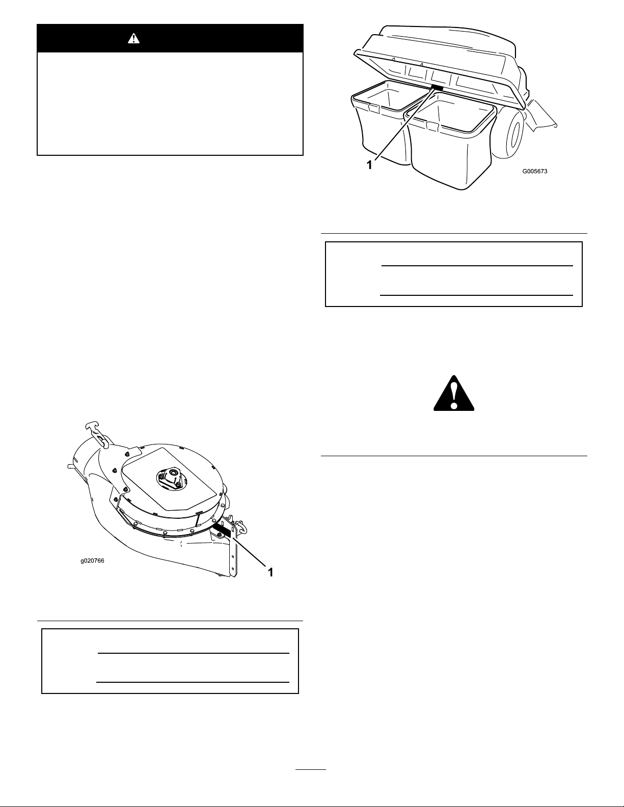
CustomerServiceandhavethemodelandserialnumbers
ofyourproductready.Figure1andFigure2identiesthe
locationofthemodelandserialnumbersontheproduct.
Writethenumbersinthespaceprovided.
1.Modelandserialnumberlocation
ModelNo.
SerialNo.
Thismanualidentiespotentialhazardsandhassafety
messagesidentiedbythesafetyalertsymbol(Figure3),
whichsignalsahazardthatmaycauseseriousinjuryordeath
ifyoudonotfollowtherecommendedprecautions.
Figure3
1.Safetyalertsymbol
Thismanualuses2otherwordstohighlightinformation.
Importantcallsattentiontospecialmechanicalinformation
andNoteemphasizesgeneralinformationworthyofspecial
attention.
1.Blowermodelandserialnumberlocation
ModelNo.
SerialNo.
©2013—TheToro®Company
8111LyndaleAvenueSouth
Bloomington,MN55420
Figure1
Contactusatwww.Toro.com.
2
PrintedintheUSA.
AllRightsReserved
Page 3

Contents
Safety
Introduction..................................................................2
Safety...........................................................................3
SafetyandInstructionalDecals.................................4
Setup............................................................................6
1PreparingtheMower.............................................7
2InstallingtheBaggerFrame....................................7
3InstallingtheHoodBafe......................................9
4InstallingtheHoodandtheHoodRod....................10
5InstallingtheBlowerAssembly..............................12
6InstallingtheBlowerBeltandPlasticBelt
Cover................................................................13
7InstallingtheDischargeTubes...............................14
8InstallingtheWeight.............................................15
Operation....................................................................17
EmptyingtheGrassBags.........................................17
ClearingObstructionsfromtheBagger
System..............................................................18
RemovingtheBagger..............................................18
OperatingTips......................................................19
Maintenance.................................................................20
RecommendedMaintenanceSchedule(s)......................20
PreparingforMaintenance.......................................20
CleaningtheHoodScreen.......................................20
CleaningtheBaggerandBags...................................21
InspectingtheBlowerBelt.......................................21
ReplacingtheBlowerBelt........................................21
GreasingtheIdlerArm...........................................21
InspectingtheBagger.............................................22
InspectingtheMowerBlades...................................22
Storage........................................................................22
StoringtheBaggerAttachment.................................22
Troubleshooting...........................................................23
WARNING
Toavoidpersonalinjury,followtheseprocedures:
•Becomefamiliarwithalloperatingandsafety
instructionsinthe
Operator's Man ual
forthe
mowerbeforeusingthisattachment.
•Neverremovethedischargetube,bags,bagger
hood,orthechutewhiletheengineisrunning.
•Alwaysshuttheengineoffandwaitforall
movingpartstostopbeforeclearingan
obstructionfromthebaggingsystem.
•Neverdomaintenanceorrepairswhilethe
engineisrunning.
WARNING
Whenthebaggerisinoperation,thebloweris
rotatingandcancutofforinjurehandsandngers.
•Beforeadjusting,cleaning,repairingand
inspectingtheblower,andbeforeunclogging
thechute,turnofftheengineandwaitforall
movingpartstostop.Removethekey.
•Useastick,notyourhands,toremovean
obstructionfromtheblowerandtube.
•Keepface,hands,feet,andanyotherpartof
yourbodyorclothingawayfromconcealed,
moving,orrotatingparts.
WARNING
Debris,suchasleaves,grass,orbrushcancatch
re.Areintheengineareacancausepersonal
injuryandpropertydamage.
•Keeptheengineandmuferareafreeofdebris
accumulation.
•Takecarewhenopeningthebaggercoverto
keepdebrisfromfallingontotheengineand
muferarea.
•Allowthemachinetocoolbeforestoringit.
WARNING
Enginescanbecomehotwhentheyareoperating .
Severeburnscanoccurfromcontactinghot
surfaces.
Allowengines,especiallythemufer,tocoolbefore
touching.
3
Page 4

ThefollowinglistcontainssafetyinformationspecictoToro
productsandothersafetyinformationyoumustknow .
•Becomefamiliarwiththesafeoperationoftheequipment,
withtheoperatorcontrols,andsafetysigns.
•Useextracarewithgrasscatchersorotherattachments.
Thesecanchangetheoperatingcharacteristicsandthe
stabilityofthemachine.
•Followthemanufacturer'srecommendationsforadding
orremovingwheelweightsorcounterweightstoimprove
stability.
•Donotuseagrasscatcheronsteepslopes.Aheavy
grasscatchercouldcauselossofcontroloroverturnthe
machine.
•Slowdownanduseextracareonhillsides.Turfconditions
canaffectthemachine'sstability.Useextremecaution
whileoperatingneardrop-offs.
•Keepallmovementonslopesslowandgradual.Donot
makesuddenchangesinspeed,directionsorturning.
•Thegrasscatchercanobstructtheviewtotherear.Use
extracarewhenoperatinginreverse.
•Usecarewhenloadingorunloadingthemachineintoa
trailerortruck.
•Neveroperatewiththedischargedeectorraised,
removedoraltered,unlessusingagrasscatcher.
•Keephandsandfeetawayfrommovingparts.Donot
makeadjustmentswiththeenginerunning.
•Stoponlevelground,disengagedrives,settheparking
brake,shutoffenginebeforeleavingtheoperator's
positionforanyreasonincludingemptyingthegrass
catcheroruncloggingthechute.
•Ifyouremovethegrasscatcher,removetheweightsand
besuretoinstallanydischargedeectororguardthat
mighthavebeenremovedtoinstallthegrasscatcher.Do
notoperatethemowerwithouteithertheentiregrass
catcherorthegrassdeectorinplace.
•Stoptheenginebeforeremovingthegrasscatcheror
uncloggingthechute.
•Useastick,notyourhands,toremoveanobstruction
fromtheblowertube.
•Donotleavegrassingrasscatcherforextendedperiods
oftime.
•Grasscatchercomponentsaresubjecttowear,damage
anddeterioration,whichcouldexposemovingpartsor
allowobjectstobethrown.Frequentlycheckcomponents
andreplacewithmanufacturer'srecommendedparts,
whennecessary.
SafetyandInstructionalDecals
Safetydecalsandinstructionsareeasilyvisibletotheoperatorandarelocatednearanyareaofpotential
danger.Replaceanydecalthatisdamagedorlost.
1-653558
109-6809
1.Crushinghazardofhand—donotremovethewholebaggerfromthemachine;openthebaggertopandthenremovethebag(s)
fromthebagger.Donotremovethebaggertopwhenitisclosed;openthebaggertopandthenremoveit.
114-1606
1.Entanglementhazard,belt—keepallguardsinplace.
4
Page 5
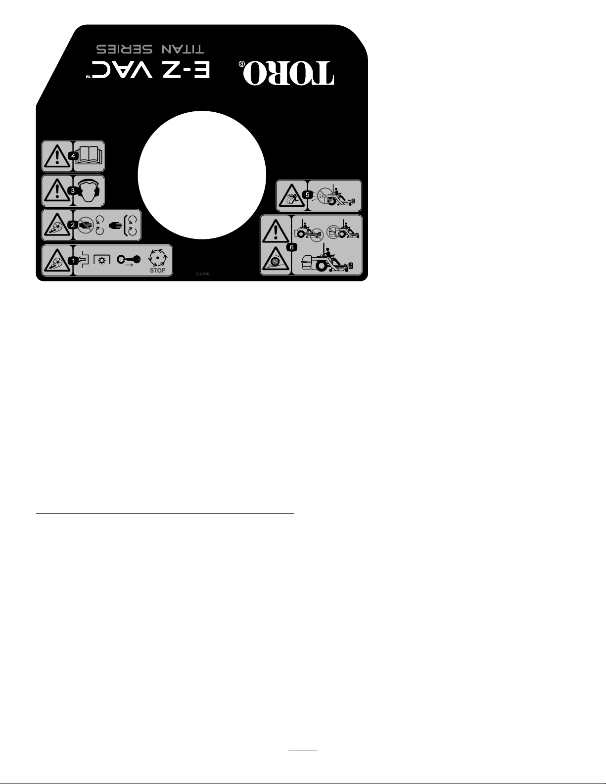
125–5502
1.Warning—readthe
Operator’sManual.
2.Warning—wearhearing
protection.
3.Cutting/dismemberment
hazard,impeller—keep
awayfrommovingparts;
keepallguardsandcovers
inplace.
4.Cutting/dismemberment
hazard,
impeller—disengagethe
PTO,removetheignition
key,andwaitforallmoving
partstostop.
5.Thrownobjecthazard—do
notruntheblowerwithout
theentirecollection
systeminstalledand
latched.
6.Warning;lossof
traction—donotoperate
onlywithcounterbalance
weightsinstalled;donot
operateonlywithE-ZVac
installed;onlyoperate
withbothE-ZV acand
counterbalanceweights
installed.
5
Page 6

Setup
LooseParts
Usethechartbelowtoverifythatallpartshavebeenshipped.
ProcedureDescription
1
2
3
4
5
6
7
8
Nopartsrequired
Baggerframesupportbracket
Plate1
Selftappingbolts(5/16x3/4inch)
Bolt(5/16x2-1/2inch)
Locknut(5/16inch)
Baggerframe
Clevispin(1/2x2-1/4inch)
Hairpincotterpin
Rod2
Washer4
Clevispin(1/2x1-1/2inch)
Spacerplate
Baggerhood1
Bafe
Hairpincotterpin(small)
Circularcotterpin
Hoodrod1
Hairpincotterpin1
Blowerassembly(fromtheBlowerand
DriveKit)
Spring(fromtheBlowerandDriveKit)
Metalbeltcover(fromtheBlowerand
DriveKit)
Plasticbeltcover(fromtheBlowerand
DriveKit)
Knobs(fromtheBlowerandDriveKit)
Blowerbelt(fromtheBlowerandDrive
Kit)
Uppertube1
Screw(1/4x3/4inches)
Washer(1/4inch)
Locknut(1/4inch)
Lowertube1
Weight2
Adhesivebumper2
Rod1
Washer(5/16inch)
Hairpincotterpin2
Qty.
Use
–
1
2
2
2
1
1
5
2
1
1
2
1
1
1
1
1
2
1
2
2
2
4
Preparethemower .
Installthebaggerframe.
Installthehoodbafeandhoodrod.
Installthehoodandthehoodrod.
Installtheblowerassembly.
Installtheblowerbeltandplasticbelt
cover.
Installthedischargetubes.
Installtheweight.
6
Page 7
1
g017921
G016263
PreparingtheMower
NoPartsRequired
Procedure
Performthefollowingproceduretopreparethemowerfor
attachingtheblowerandbaggerkit.
1.DisengagethePTO,movethemotioncontrolleversto
theneutrallockedposition,andsettheparkingbrake.
2.Stoptheengine,removethekey,andwaitforallmoving
partstostopbeforeleavingtheoperatingposition.
3.Repairallbentordamagedareasofthemowerdeck
andreplaceanymissingparts.
4.Cleanthemowerofanydebrisonthedeckorrearpart
ofthemowertoeaseinstallation.
2
InstallingtheBaggerFrame
Partsneededforthisprocedure:
1
Baggerframesupportbracket
1Plate
2
Selftappingbolts(5/16x3/4inch)
2
Bolt(5/16x2-1/2inch)
2
Locknut(5/16inch)
1
Baggerframe
1
Clevispin(1/2x2-1/4inch)
5
Hairpincotterpin
2Rod
4Washer
2
Clevispin(1/2x1-1/2inch)
1
Spacerplate
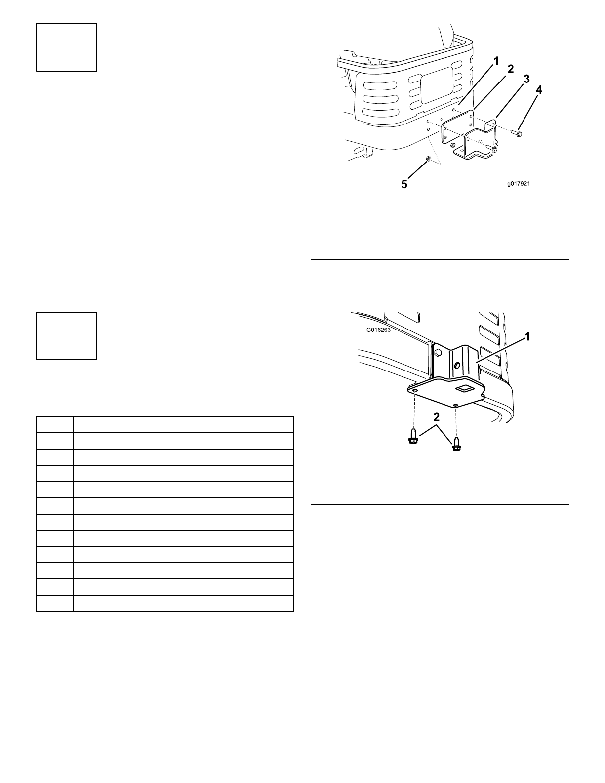
Figure4
1.Machineframe4.Bolt(5/16x2-1/2inch)
2.Plate
3.Supportbracket
3.Securethesupportbrackettothebottomofthe
machineframefrombelowusing2newself-tapping
screws(5/16x3/4inch)asshowninFigure5.
1.Supportbracket2.Self-tappingbolts(5/16x
4.Removethefastenerssecuringtheexistingrectangular
spacerplatefromthetopoftheengineframeand
removetheplate,ifsoequipped.
5.InstallthenewspacerplateasshowninFigure6using
thefastenersremovedpreviously.
6.Installthebaggerframetothesupportbracket.Secure
thebaggerframewithaclevispin(1/2x2-1/4inch)
andhairpincotterpin(Figure6).
5.Locknut(5/16inch)
Figure5
3/4inch)
Procedure
1.Removetheexistingselftappingboltsinthebottomof
themachineframe(Figure5).Discardthebolts.
2.Installthesupportspacerplateandthesupportbracket
tothemachineframeasshowninFigure4.Securethe
plateandbrackettotheframeusingtwobolts(5/16x
2-1/2inch)andtwolocknuts(5/16inch).
7
Page 8
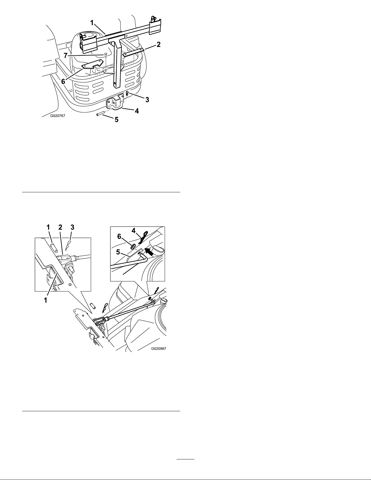
G020767
Figure6
G020997
5
6
4
1 2 3
1
1.Baggerframe5.Clevispin(1/2x2-1/4
2.Removetheexisting
rectangularspacerplate
(ifsoequipped)
3.Hairpin
4.Supportbracket
inch)
6.Newspacerplate
7.Existingfasteners
9.Adjustthesupportrodssothatbaggerframeisheld
securetothemachineframeandsitsinthenotchof
theanglespacerplateinstalledpreviously .Repeatthese
stepsforeachsupportrod:
A.Loosenthejamnutatthebaseoftheclevisend
oftherod.
B.Rotatetheclevisendoftherodtoadjusttherod
tothedesiredlength.
C.Aligntheholesintheclevisendwiththeholein
thebaggerframeattheattachmentpoint.
D.Securetheclevisendoftherodstothebagger
frameusingaclevispinandhairpincotter
Figure7).
pin(
E.Tightenthejamnut.
10.Withbothrodsinstalledandattached,checkthebagger
frameforplay.Thebaggerframeshouldbeheldtight
tothemachineframe.Ifnecessary,repeattheprevious
steptosecurethebaggerframe.
7.Installtwosupportrods,onetoeachsideofthebagger
frame.Locatetheexistingbracketbetweentherear
drivewheelandframe(Figure7).
Leftsideshown
Figure7
1.Baggerframe
2.Clevisend5.Bracketonframe
3.Clevispin(1/2x1-1/2
inch)
8.Insertthebentendsoftherodintothebaggerframe
asshowninFigure7.Securetheendoftherodwitha
washerandhairpincotterpin.
4.Hairpin
6.Washer
8
Page 9

3
G018355
1
2
3
4
5
6
g018354
1
2 3 4
6
5
InstallingtheHoodBafe
Partsneededforthisprocedure:
1Baggerhood
1
Bafe
2
Hairpincotterpin(small)
Procedure
1.Locatethebafeslotsinthefrontandbacksidewalls
ofthebaggerhood,andthemountingtabsonthe
hoodbafe(Figure8).
6.Securethebafetothehoodbyinsertingthehairpins
intotheholesinthebafe-mountingtabsasshown
inFigure9.
Figure9
BaggerHoodAssembly
Figure8
Hood,Bafe,andHairpin
1.Hairpincotterpin(small)4.Bafeslot
2.BaggerHood
3.Bafe-mountingtab
5.Bafe
6.Ductseal
1.Hairpincotterpin
2.BaggerHood
3.Bafe-mountingtab
4.Bafeslot
5.Bafe
6.Ductseal
2.Positionthehoodsothattheductsealisonyourleft,
asillustratedinFigure8.
3.Alignthebafesothatthescreenedareaisupand
angledleft(Figure8).
4.Insertthebafeupintothehoodfromthebottom
Figure8).
(
5.Alignthebafe-mountingtabswiththebafeslotsin
thehood,andpushthemountingtabsupandthrough
theslots(Figure8).
9
Page 10

4
G021382
3
1
2
G016265
InstallingtheHoodandthe HoodRod
Partsneededforthisprocedure:
1
Circularcotterpin
1Hoodrod
1Hairpincotterpin
Procedure
Note:Thebaggerhoodiseasiertoinstallwhentwopeople
worktogether.
1.Installthehoodrodtothebaggerframewithahairpin
cotterpin.Installthehairpincotterpinfromthe
bottom(Figure10).
Figure11
Figure10
1.Baggerframe3.Hairpincotterpin(install
fromthebottom)
2.Hoodrod
2.Installthebaggerhoodtothebaggerframe.
3.Slidethebracketsoverthepostsinthebaggerframe
andinstallthecircularcotterpinintotheholeinthe
righthandpost(Figure11).
4.Rotatethebaggerhooddowntotheoperatingposition.
Note:Toremovethecircularcotterpin,continueto
rotateitinthesamedirectionasinstalled.
1.Baggerhood
2.Baggerframe
3.Bracket,baggerhood
4.Circularcotterpin
5.Post
10
Page 11

5.Liftthebaggerhoodandinstallthebagsbysliding
G005672
1
2
3
4
G005757
g018363
1
2
3
thebagframehooksontotheretainingbrackets
(Figure12).
Figure14
1.Rubberhoodlatch3.Latchedposition
2.Hoodrodend
Figure12
1.Bag3.Retainingbracket
2.Baggerframe4.Bagframehook
6.Lowerthebaggerhoodontothebag(Figure13).
Figure13
7.Aligntheholeintherubberhoodlatchwiththehood
rod(Figure14).
8.Pushthehoodlatchovertheendofthehoodrodas
showninFigure14.
11
Page 12

5
1
2
3
g020999
4
InstallingtheBlowerAssembly
Partsneededforthisprocedure:
1
Blowerassembly(fromtheBlowerandDriveKit)
1
Spring(fromtheBlowerandDriveKit)
1
Metalbeltcover(fromtheBlowerandDriveKit)
Procedure
WARNING
Anuncovereddischargeopeningcouldallowthe
lawnmowertothrowobjectsintheoperator'sor
bystander'sdirectionandresultinseriousinjury.
Also,contactwiththebladecouldoccur.
•Neveroperatethelawnmowerunlessyouinstall
acoverplate,amulchplate,oragrasschuteand
catcher.
•Makesurethatthegrassdeectorisinstalled
whenyouremovethegrasschuteandcatcher.
Important:Installtheside-dischargechutewhenyou
removethebaggerandblower.
Important:Saveallthehardwareandtheside-discharge
chute.
1.Ifnecessary,installthebeltontotheblowerpulley
(
Figure18).
2.Lowertheblowerandslidethepivotholeontothe
pivotpin(
Note:Ensurethatthebeltremainspositionedin
theblowerpulleyandtherubberapontheblower
remainsontheoutsideofthemowerdeck(Figure15).
Figure15).
Figure15
1.Blowerassembly3.Mowerdeck
2.Pivotpin
3.Movethelatchpinfromthelockingpositiontothe
openposition(Figure16).
4.Closetheblowerassemblyandalignthelatchpinwith
theholeintheblowersupport.
5.Movethelatchpintothelockingposition(Figure16).
Note:Ensurethatthelatchpinextendsthroughthe
holeinblowersupport(Figure16).
Note:Ensurethatthelatchrmlyholdstheblower
assemblyagainstthemowerdeck,butcanbereleased
byhand.
4.Rubberap
12
Page 13

g021000
2
1
1
4
3
5
6
7
Figure16
G020769
1
2
3
4
g020950
6 5
1 2 3 4
1.Latchpin(openposition)5.Spring
2.Latchpin(lockingposition)6.Shoulderbolt
3.Blowersupport7.Idlerpulleypost
4.Blowerassembly
6
InstallingtheBlowerBeltand PlasticBeltCover
Partsneededforthisprocedure:
Figure17
BlowerBeltRouting
1.Drivepulley3.Blowerpulley
2.Blowerbelt
BlowerBeltRouting
4.Idler/tensionpulley
Figure18
1
Plasticbeltcover(fromtheBlowerandDriveKit)
2
Knobs(fromtheBlowerandDriveKit)
1
Blowerbelt(fromtheBlowerandDriveKit)
Procedure
1.Ifneeded,installthebeltaroundtheblower
pulley(Figure17andFigure18).Referto
5InstallingtheBlowerAssembly(page12).
1.Drivepulley
2.Mowerdeck5.Blowerpulley
3.Idler/tensionpulley
2.Ensurethatthebeltremainsalignedtotheblower
pulleywhileyouareinstallingtheblowerassembly.
3.Routethebeltaroundthedrivepulleyasillustratedin
Figure17andFigure18.
4.Temporarilyroutethebeltbeneaththeidlerpulley
(Figure18).
5.Installthespringontotheidlerpulleypost(Figure16).
6.Installthespringontotheshoulderbolt(
7.Pullthespringloadedidlerpulleyawayfromthexed
springpost,androutethebeltaroundthemowerdeck
pulley(Figure18).
4.Blowerinposition(housing
portionremovedfor
illustrativepurposes)
6.Blowerbelt
Figure16).
13
Page 14

Note:Ensurethebeltisroutedaroundtheblower
3
1
2
g020923
3
G018444
1
2
pulleycorrectly.
2.Stoptheengine,removethekey,andwaitforallmoving
partstostopbeforeleavingtheoperatingposition.
8.Aligntheplasticbeltcoveroverthedrivepulleyand
belt.
9.Securetheplasticbeltcovertotheblowersupportand
themetalbeltcoverwith2knobs(
Figure19).
3.Lowerthemowerdecktothelowestheight-of-cut
position.
4.Removethebagsforviewingthetubeunderthehood.
5.Lowerandlatchthehood.
6.Usebothlatchestoattachthelowertubetotheblower
assembly(
Note:Ensurethenotchinthelowertubeisatthe
bottomwheninstalled(
Figure20).
Figure22).
Figure19
1.Plasticbeltcover3.Metalbeltcoverinstalled
2.Knob
7
InstallingtheDischargeTubes
Partsneededforthisprocedure:
1Uppertube
2
Screw(1/4x3/4inches)
2
Washer(1/4inch)
2
Locknut(1/4inch)
1Lowertube
Procedure
Important:Makesurethatthemowerdeckisinthe
lowestheight-of-cutpositionbeforeinstallingthe
dischargetubes.
Note:Remembertoinstallthegrassdeectorwhenyou
removethebaggerfromthemower.
1.DisengagethePTOandsettheparkingbrake.
Figure20
LowerDischargeTubeLatch
1.Blowerassembly3.Latch
2.Upperlatch
7.Makenoteofwherethetwoboltsintheuppertube
areinstalled.
Note:Theholenearthemoldedarrowheadswillnot
beused.
8.Removethetwoboltsinthelowerendoftheupper
tube.Usethe2holesasatemplateforthelowertube.
Retainthehardware.
9.Inserttheupperend(noholes)oftheuppertube
throughthetubesealinthehoodbypushingthetube
inuntilthetubecontactstheinsideofthehood,
10.Pulltheuppertubeoutslightlysothatthesealextends
outwardandoverthelowertube(Figure21).
14
Page 15

G018440
1
2
3
Figure21
g021002
1 2
4 3
5
g021003
4
2
3
1
5
9
8
7
6
1.Uppertube3.Baggerhood
2.Rubbersealprotrudingout
11.Aligntheuppertubeholestomatchthedimplesonthe
surfaceofthelowertube.
Note:Ensurethesideprolelookssimilartowhatis
showninFigure22.
Figure23
DrillingLowerDischargeTube
1.Dimples6.Upper-tube,existingholes
2.Lowertube7.Hexkeytool
3.Drill1/4inch(6.5mm)
diameterhole
4.Uppertube
5.Locknut(1/4inch)
8.Washer(1/4inch)
9.Screw(1/4x3/4inch)
13.Removetheupperandlowertubesfromthemachine.
14.Slidethetubestogetherandaligntheholes.
Figure22
1.Uppertube4.Lowertube
2.Existinghole(bolt
removed)
3.Notchatthebottomof
tubewheninstalled
12.Usingtheexistingholesintheuppertubeasatemplate,
drill2holes,a1/4inch(6.5mm)diameter,throughthe
5.Donotuseopenholenear
themoldedarrowheads
dimplesonthelowertube(Figure23).
15.Installthewashers(1/4inch)ontothebolts(Figure23).
16.Usingahexkeytool,installthescrews(1/4x3/4inch)
andwashers(1/4inch)fromtheinsideofthelower
tubeandthroughtheexistingholesintheuppertube
(Figure23).
17.Securethetubestogetherwiththenuts(1/4inch)
(Figure23).
18.Inserttheupperdischargetubethroughthetubeseal
inthehood.
19.Pulltheuppertubeoutslightlysothatthesealextends
outwardandovertheblowerassembly(Figure21).
20.Usebothlatchestoattachthelowertubetotheblower
assembly(
15
Figure20).
Page 16

8
G016271
1
2
3
4
5
G010701
1
2
3
4
InstallingtheWeight
Partsneededforthisprocedure:
2Weight
2Adhesivebumper
1Rod
4
Washer(5/16inch)
2Hairpincotterpin
Figure25
1.Cutawayofthefrontofthe
machineframe
2.Bumper4.Resttheweighthere
3.Weight
duringinstall
Procedure
1.Installanadhesivebumpertotheweight(Figure1).
Figure24
1.Adhesivebumper4.Hairpin
2.Frontweight5.Washer
3.Rod
Note:OnTitanMXmachinesandthe60inchZX
machine,disconnectthefrontdeckpanfromtheframe
toallowinstallationoftheweights.Ensurethepanis
installedoncetheweightsaresecured.
Important:Wheneveryouremovethebagger
attachment,remembertoremovethefrontweight
toreturntheproperstabilitytothemachine.
2.Installtheweighttothefrontofthemachineframe.
Securetheweightwitharod,fourwashers,andtwo
hairpinsasshowninFigure24.
Note:Wheninstallingthefrontweightallowittorest
onthefrontlipoftheundersideofthemachineframe
asshownFigure25.Thiswillsuspendtheweightwhile
yousecureittothemachine.Usecarenottodislodge
theweightwheninstallingthesupportingrod.
16
Page 17

Operation
G005758
G005672
1
2
3
4
Note:Determinetheleftandrightsidesofthemachine
fromthenormaloperatingposition.
WARNING
Toavoidpersonalinjury,followtheseprocedures:
•Becomefamiliarwithalloperatingandsafety
instructionsinthe
Operator's Man ual
mowerbeforeusingthisattachment.
•Neverremovethedischargetube,bags,bagger
hood,orthechutewhiletheengineisrunning.
•Alwaysshuttheengineoffandwaitforall
movingpartstostopbeforeclearingan
obstructionfromthebaggingsystem.
•Neverdomaintenanceorrepairswhilethe
engineisrunning.
EmptyingtheGrassBags
forthe
Becarefulwhenliftingorhandlingagrassbagthatisfull.To
emptythegrassbags:
1.Parkthemachineonalevelsurfaceanddisengagethe
bladecontrolswitch.
2.Movethemotioncontrolleversoutwardtotheneutral
lockposition,stoptheengine,removethekey ,setthe
parkingbrakeandwaitforallmovingpartstostop
beforeleavingtheoperatingposition.
3.Open(raise)thebaggerhood(Figure26).
Figure26
Figure27
1.Bag3.Retainingbracket
2.Baggerframe4.Bagframehook
6.Lowerthebaggerhoodontothebags.
4.Compressdebrisintothebags.Withbothhands,liftup
onthebagandunhookitfromtheretainingbracket.
Emptythebag.Repeattheprocedurefortheotherbag.
5.Installthebagsbyslidingthebagframehooksontothe
retainingbrackets(
Figure27).
17
Page 18

ClearingObstructionsfrom
CAUTION
theBaggerSystem
WARNING
Whenthebaggerisinoperation,thebloweris
rotatingandcancutofforinjurehandsandngers.
•Beforeadjusting,cleaning,repairingand
inspectingtheblower,andbeforeunclogging
thechute,turnofftheengineandwaitforall
movingpartstostop.Removethekey.
•Useastick,notyourhands,toremovean
obstructionfromtheblowerandtube.
•Keepface,hands,feet,andanyotherpartof
yourbodyorclothingawayfromconcealed,
moving,orrotatingparts.
1.DisengagethePTOandsettheparkingbrake.
2.Turnofftheengine,removethekey ,andwaitforall
movingpartstostopbeforeleavingtheoperating
position.
3.Emptythebags.
Failingtoremovethefrontbaggerweights
andoperatingthemachinewithoutthebagger
attachmentmaycauseanunstableconditionwhich
couldresultinalossofcontrol.
Alwaysremovethefrontweightswhenremoving
thebaggerattachment.
Removethebaggerbyrepeatingthesetupsectionsfromthe
InstallationInstructionsandOperator’sManualinreverseorder.
Alwaysremovethefrontbafesandfrontweightswhen
removingthebaggerattachments.
Important:Installtheside-dischargechutewhenyou
removethebaggerandblower.
Note:Itisonlynecessarytoremovethecutoffbafewhen
installingamulchingkit.
4.Unlatchthelowertube.
5.Removethetubesfromthebagger.
6.Useastickorsimilarobject,notyourhands,toremove
andcleartheobstructionfromthetubeassembly.
Note:Inmostcases,youcanshakethedebrisoutof
thetubes.
7.Iftheblowerassemblyisplugged,removetheplastic
beltcover,unlatchthebaggerblowerassembly,remove
thebelt,andswingitopen.
8.Useastickorsimilarobject,notyourhands,toremove
andcleartheobstructionfromtheblowerassembly.
9.Afteryouremovetheobstruction,installthecomplete
baggersystemandresumeoperation.
RemovingtheBagger
WARNING
Componentsaroundenginewillbehotifthe
machinehasbeenrunning.Touchinghot
componentscancauseburns.
•Donottouchenginecomponentswhenhot.
•Allowenginetocoolbeforeremovingthebagger.
18
Page 19

OperatingTips
TipsforBagging
Size
Rememberthatthemowerislongerandwiderwiththis
attachmentinstalled.Byturningtoosharplyinconned
placesyoumaydamagetheattachment.
Trimming
CAUTION
Asthebaggerlls,extraweightisaddedtotheback
ofthemachine.Ifyoustopandstartsuddenlyon
hills,youmaylosesteeringcontrolorthemachine
maytip.
•Donotstartorstopsuddenlywhengoinguphill
ordownhill.Avoiduphillstarts.
•Ifyoudostopthemachinewhengoinguphill,
disengagethebladecontrol.Thenbackdown
thehillusingaslowspeed.
Alwaystrimwiththeleftsideofthemower.Donottrim
withtherightsideofthemowerbecauseyoucoulddamage
thebagger'schuteanddischargetube.
CuttingHeight
Donotsetthemowercuttingheighttoolowbecauselong
grasssurroundingthemowercanpreventairfromgetting
underthemowerandenteringthebaggingsystem.Ifenough
airdoesn'tgetunderthemower,thebaggingsystemwillplug.
CuttingFrequency
Cutthegrassoften,especiallywhenitgrowsrapidly.Youwill
havetocutyourgrasstwiceifitgetsexcessivelylong.
CuttingTechnique
Forbestlawnappearance,besuretoslightlyoverlapthe
mowerintothepreviouslycutarea.Thishelpsreducethe
loadontheengineandreducesthechanceofpluggingthe
chuteanddischargetube.
•Donotchangespeedsorstoponslopes.
•Neveroperatethemachinewithoutthebagger
attachmentandthefrontweightsstillinstalled.
BaggingLongGrass
BaggingLongGrassExcessivelylonggrassisheavyand
maynotbepropelledcompletelyintothegrassbags.Ifthis
happens,thedischargetubeandchutemayplug.Toavoid
pluggingthebaggingsystem,mowthegrassatahighheight
ofcut,thenlowerthemowertoyournormalcuttingheight
andrepeatthebaggingprocess.
BaggingWetGrass
Alwaystrytocutgrasswhenitisdrybecauseyourlawnwill
haveaneatappearance.Ifyoumustcutwetgrass,usethe
conventionalsidedischargefeatureofthemower.Several
hourslater,whentheclippingsaredry,installthecomplete
baggerattachmentandvacuumupthegrassclippings.
SignsofPlugging
BaggingSpeed
MostoftenyouwillbagwiththemowerthrottleintheFast
positionanddriveatanormalgroundspeed.However,
inextremelydryanddustygrass,youmaywanttoslightly
reducethethrottlespeedandincreasethegroundspeed
ofthemower.Thebaggingsystemmayplugifyoudrive
toofastandtheenginespeedgetstooslow.Onhillsitmay
benecessarytoslowthemowergroundspeed.Thishelps
maintaintheenginespeedandbaggingefciency.Mow
downhillwheneverpossible.
Asyouarebagging,asmallamountofgrassclippings
normallyblowoutthefrontofthemower.Anexcessive
amountofclippingsblowingoutindicatesthatthebagsare
fullorthesystemisplugged.
19
Page 20

Maintenance
Note:Determinetheleftandrightsidesofthemachinefromthenormaloperatingposition.
RecommendedMaintenanceSchedule(s)
MaintenanceService
Interval
Aftertherst8hours
Aftereachuse
Every25hours
Every50hours
Every100hours
MaintenanceProcedure
•Inspecttheblowerbelt.
•Inspectthebagger.
•Cleanthehoodscreen.
•Cleanthebagger.
•Inspecttheblowerbelt.
•Greasetheidlerarm.
•Inspectthebagger.
WARNING
Ifyouleavethekeyintheignitionswitch,someonecouldaccidentlystarttheengineandseriouslyinjure
youorotherbystanders.
Removethekeyfromtheignitionanddisconnectthewirefromthesparkplugbeforeyoudoany
maintenance.Setthewireasidesothatitdoesnotaccidentallycontactthesparkplug.
WARNING
Enginescanbecomehotwhentheyareoperating.Severeburnscanoccurfromcontactinghotsurfaces.
Allowengines,especiallythemufer,tocoolbeforetouching.
WARNING
Debris,suchasleaves,grass,orbrushcancatchre.Areintheengineareacancausepersonalinjury
andpropertydamage.
•Keeptheengineandmuferareafreeofdebrisaccumulation.
•Takecarewhenopeningthebaggercovertokeepdebrisfromfallingontotheengineandmuferarea.
•Allowthemachinetocoolbeforestoringit.
PreparingforMaintenance
Dothefollowingstepsbeforepreformingmaintenanceon
themachine:
1.Parkthemachineonalevelsurface.
2.DisengagethePTO,movethemotioncontrolleversto
theneutrallockedposition,andsettheparkingbrake.
3.Stoptheengine,removethekey,andwaitforallmoving
partstostopbeforeleavingtheoperatingposition.
4.Cleanthemowerofanydebrisonthedeckorrearpart
ofthemowertoeasemaintenance.
CleaningtheHoodScreen
ServiceInterval:Aftereachuse
1.Disengagethepowertakeoff(PTO)andsetthe
parkingbrake.
2.Turnofftheengine,removethekey ,andwaitforall
movingpartstostopbeforeleavingtheoperating
position.
3.Openthebaggerhood.
4.Cleanthedebrisfromthescreen.
5.Closethebaggerhood.
20
Page 21

CleaningtheBaggerandBags
g020950
6 5
1 2 3 4
g020948
2
1
3
g020947
ServiceInterval:Aftereachuse
1.Washtheinsideandoutsideofthebaggerhood,bags,
tube,andtheundersideofthemower.
Note:Useamildautomotivedetergenttoremovedirt.
2.Makesurethatyouremovemattedgrassfromallparts.
7.Removetheexistingbaggerbeltfromtheblower
pulleys.
8.Installthenewbeltaroundtheblowerpulleys
(Figure28).
9.Installtheblowerontotheblowersupport.
10.Installthenewbeltaroundthemower-deckpulley
Figure28).
(
3.Afterwashingallparts,letthemdrythoroughly.
Note:Withallpartsinstalled,startandrunthemachinefor
aminutetoassistindrying.
InspectingtheBlowerBelt
ServiceInterval:Aftertherst8hours
Every25hours
Checkbeltsforcracks,frayededges,burnmarksoranyother
damage.Replacedamagedbelts.
ReplacingtheBlowerBelt
1.DisengagethePTO,movethemotioncontrolleversto
theneutrallockedposition,andsettheparkingbrake.
2.Stoptheengine,removethekey,andwaitforallmoving
partstostopbeforeleavingtheoperatingposition.
3.Removetheplasticbeltcover.
4.Pullbackonthespring-loadedidlerpulleytorelieve
thebelttension(
Figure28).
11.Installthespringontotheidlerpulleypost(Figure29).
12.Stretchandinstallthespringontotheshoulderbolt
Figure29).
(
Figure29
1.Spring-loadedidlerpulley3.Shoulderbolt
2.Idlerpulleypost
13.Pullbackonthespringloadedidlerpulleyandinstall
thebeltontothespringloadedidlerpulley(Figure28).
Figure28
1.Drivepulley
2.Mowerdeck5.Blowerpulley
3.Idler/tensionpulley
4.Blowerinposition(housing
portionremovedfor
illustrativepurposes)
6.Blowerbelt
5.Removetheexistingbaggerbeltfromthemower-deck
pulley.
6.Removetheblowerfromthemowerdeck.
GreasingtheIdlerArm
ServiceInterval:Every50hours
Figure30
21
Page 22

InspectingtheBagger
ServiceInterval:Every100hours
Aftertherst8hours
1.DisengagethePTO,movethemotioncontrolleversto
theneutrallockedposition,andsettheparkingbrake.
2.Stoptheengine,removethekey,andwaitforallmoving
partstostopbeforeleavingtheoperatingposition.
3.Checktheuppertube,lowertube,baggerhood,and
theblowerassembly.
Note:Replacethesepartsiftheyarecrackedor
broken.
4.Checkthebags,baggerframe,andscreen.
Note:Replaceanypartsthatarecrackedorbroken.
5.Tightenallnutsboltsandscrews.
InspectingtheMowerBlades
1.Inspectthemowerbladesregularlyandwhenevera
bladestrikesaforeignobject.
Storage
StoringtheBaggerAttachment
1.Cleanthebaggerattachment;refertoCleaningthe
BaggerAttachment.
2.Inspectthebaggerattachmentfordamage;referto
InspectingtheBaggerAttachment.
3.Makesurethegrassbagsareemptyandthoroughlydry.
4.Storethebaggerinaclean,dryplace,outofdirect
sunlight.Thisprotectstheplasticpartsandextendsthe
lifeofthebagger.Ifyoumuststorethebaggeroutside,
coveritwithaweatherproofcover.
2.Ifbladesarebadlywornordamaged,installnewblades.
RefertoyourmachineOperator'sManualforcomplete
blademaintenance.
22
Page 23

Troubleshooting
Problem
Abnormalvibration.
Reducedbaggingperformance.
Blowerandtubesplugtoofrequently .
PossibleCauseCorrectiveAction
1.Cuttingblade(s)is/arebentor
unbalanced.
2.Blade-mountingboltisloose.2.Tightentheblade-mountingbolt.
3.Looseblowerpulleyorpulleyassembly .3.Tightentheappropriatepulley.
4.Wornbaggerbelt.4.Replacethebelt.
5.Blowerfanblade(s)is/arebentor
unbalanced.
1.Lowenginespeed.
2.Pluggedscreeninbaggerhood.2.Removedebris,leavesorgrass
3.Loosebaggerbelt.3.Replacethebaggerbelt.
4.Apluggedtubeorblower.4.Locateandremovepluggeddebris.
5.Fullbags.5.Emptythehopper.
1.Bagsaretoofull.1.Dumpmorefrequently .
2.Lowenginespeed.
3.Grassistoowet.3.Cutgrasswhenitisdry.
4.Grassistoolong.4.Cutnomorethan51-76mm(2-3
5.Pluggedscreeninhood.5.Removedebris,leavesorgrass
6.Groundspeedistoofast.6.Drivesloweratfullthrottle.
7.Wornbaggerbelt.7.Replacebelt.
1.Installnewcuttingblade(s).
5.ContactanAuthorizedServiceDealer.
1.Alwaysoperatetheengineatfull
throttle.
clippingsfromthescreen.
2.Alwaysoperatetheengineatfull
throttle.
inches)or1/3ofthegrassheight,
whicheverisless.
clippingsfromthescreen.
Debrisblowout.
Blowerimpellerdoesnotspinfreely.
1.Bagsaretoofull.1.Dumpmorefrequently .
2.Groundspeedistoofast.
3.Mowerdeckisnotleveled.
1.Pluggedblower.1.Removedebris,leavesorgrass
2.Impellernotaligned.
2.Drivethemachineatslowground
speedwhileoperatingtheengineatfull
throttle.
3.SeethemachineOperator'sManualfor
levelingthemowerdeck.
clippingsfromtheblowerimpeller.
2.ContactanAuthorizedServiceDealer.
23
Page 24

TheToroTotalCoverageWarranty
LimitedWarranty(seewarrantyperiodsbelow)
TimeCutter
and
TITAN
Mowers
ConditionsandProductsCovered
TheT oroCompanyanditsafliate,T oroWarrantyCompany,pursuantto
anagreementbetweenthem,jointlypromisetotheoriginalpurchaser
torepairtheT oroProductslistedbelowifdefectiveinmaterialsor
workmanship.
Thefollowingtimeperiodsapplyfromthedateofpurchasebytheoriginal
owner:
ProductsWarrantyPeriod
TimeCutterandMXMowers
•Engines
1
Residentialuse
—ResidentialuseKawasaki–3years
2
–3years
Kohler–3years
Toro–3years
TimeCutterandMXMowersCommercialuse30days
•Engines
1
—Commercialuse
Kawasaki–3years
Kohler–90days
Toro–90days
TITANMowers–Residentialor
Commercialuse
•Engines
1
—Residentialor
Commercialuse
•Frame
TITANMXMowers–Residentialor
Commercialuse
•Engines
1
—Residentialor
Commercialuse
•Frame
3yearsor240hours
Kawasaki–3years
Kohler–2years
Lifetime(originalowneronly)
3yearsor400hours
Kawasaki–3years
Kohler–2years
Lifetime(originalowneronly)
3
4
3
4
AllMowers
•Attachments1year
•Battery90daysPartsandLabor
1yearPartsonly
•BeltsandTires90days
1
SomeenginesusedonToroProductsarewarrantedbytheenginemanufacturer.
2
Residentialusemeansuseoftheproductonthesamelotasyourhome.Useatmorethanone
locationisconsideredcommercialuseandthecommercialusewarrantywouldapply.
3
Whicheveroccursrst.
4
LifetimeFrameWarranty-Ifthemainframe,consistingofthepartsweldedtogethertoformthe
tractorstructurethatothercomponentssuchastheenginearesecuredto,cracksorbreaksin
normaluse,itwillberepairedorreplaced,atToro'soption,underwarrantyatnocostforparts
andlabor .Framefailureduetomisuseorabuseandfailureorrepairrequiredduetorustor
corrosionarenotcovered.
Thiswarrantyincludesthecostofpartsandlabor,butyoumustpay
transportationcosts.
Warrantymaybedeniedifthehourmeterisdisconnected,altered,or
showssignsofbeingtamperedwith.
OwnerResponsibilities
YoumustmaintainyourToroProductbyfollowingthemaintenance
proceduresdescribedintheOperator'sManual.Suchroutine
maintenance,whetherperformedbyadealerorbyyou,isatyourexpense.
InstructionsforObtainingWarrantyService
IfyouthinkthatyourT oroProductcontainsadefectinmaterialsor
workmanship,followthisprocedure:
1.ContactanyAuthorizedToroServiceDealertoarrangeservice
attheirdealership.Tolocateadealerconvenienttoyou,referto
theYellowPagesofyourtelephonedirectory(lookunder“Lawn
Mowers”)oraccessourwebsiteatwww .Toro.com.Y oumayalso
callthenumberslistedinitem#3tousethe24-hourT oroDealer
locatorsystem.
2.Bringtheproductandyourproofofpurchase(salesreceipt)tothe
ServiceDealer.Thedealerwilldiagnosetheproblemanddetermine
ifitiscoveredunderwarranty.
3.IfforanyreasonyouaredissatisedwiththeServiceDealer’s
analysisorwiththeassistanceprovided,contactusat:
CustomerCareDepartment,RLCDivision
ToroWarrantyCompany
811 1LyndaleAvenueSouth
Bloomington,MN55420-1 196
Tollfreeat866-216-6029(U.S.customers)
Tollfreeat866-216-6030(Canadiancustomers)
ItemsandConditionsNotCovered
Thereisnootherexpresswarrantyexceptforspecialemissionsystem
coverageandenginewarrantycoverageonsomeproducts.Thisexpress
warrantydoesnotcoverthefollowing:
•Costofregularmaintenanceserviceorparts,suchaslters,fuel,
lubricants,oilchanges,sparkplugs,airlters,bladesharpening/worn
bladeonmowers,cable/linkageadjustments,orbrakeandclutch
adjustments
•Componentsfailingduetonormalwear
•Anyproductorpartwhichhasbeenalteredormisusedandrequires
replacementorrepairduetoaccidentsorlackofpropermaintenance
•Repairsnecessaryduetoimproperbatterycare,failuretousefresh
fuel(lessthanonemonthold),orfailuretoproperlypreparetheunit
priortoanyperiodofnon-useoveronemonth
•Pickupanddeliverycharges
•Operationalmisuse,neglect,oraccidents
•RepairsorattemptedrepairsbyanyoneotherthananAuthorized
ToroServiceDealer
GeneralConditions
Allrepairscoveredbythesewarrantiesmustbeperformedbyan
AuthorizedT oroServiceDealerusingToroapprovedreplacementparts.
NeitherTheToroCompanynorToroWarrantyCompanyisliablefor
indirect,incidentalorconsequentialdamagesinconnectionwiththe
useoftheToroProductscoveredbythiswarranty ,includingany
costorexpenseofprovidingsubstituteequipmentorserviceduring
reasonableperiodsofmalfunctionornon-usependingcompletion
ofrepairsunderthiswarranty.
Allimpliedwarrantiesofmerchantability(thattheproductistfor
ordinaryuse)andtnessforuse(thattheproductistforaparticular
purpose)arelimitedtothedurationoftheexpresswarranty.
Somestatesdonotallowexclusionsofincidentalorconsequential
damages,orlimitationsonhowlonganimpliedwarrantylasts,so
theaboveexclusionsandlimitationsmaynotapplytoyou.
Thiswarrantygivesyouspeciclegalrights,andyoumayalsohaveother
rightswhichvaryfromstatetostate.
CountriesOtherthantheUnitedStatesorCanada
CustomerswhohavepurchasedT oroproductsoutsidetheUnitedStatesorCanadashouldcontacttheirT oroDistributor(Dealer)toobtainguarantee
policiesforyourcountry,province,orstate.IfforanyreasonyouaredissatisedwithyourDistributor'sserviceorhavedifcultyobtainingguarantee
information,contacttheT oroimporter.Ifallotherremediesfail,youmaycontactusatT oroWarrantyCompany.
AustralianConsumerLaw:AustraliancustomerswillnddetailsrelatingtotheAustralianConsumerLaweitherinsidetheboxoratyourlocalT oro
Dealer.
374-0258RevD
 Loading...