

Toro 79324 Operator's Manual

42inand50inTwinBagger
FormNo.3359-984RevB
forTimeCutter
®
Z4000andZ5000Series
RidingMower
ModelNo.79324—SerialNo.280000001andUp
Registeratwww.T oro.com.OriginalInstructions(EN)
Introduction
Readthisinformationcarefullytolearnhowtooperate
andmaintainyourproductproperlyandtoavoidinjury
andproductdamage.Youareresponsibleforoperating
theproductproperlyandsafely.
Thismanualuses2otherwordstohighlightinformation.
Importantcallsattentiontospecialmechanical
informationandNoteemphasizesgeneralinformation
worthyofspecialattention.
Contents
YoumaycontactTorodirectlyatwww.Toro.comfor
productandaccessoryinformation,helpndinga
dealer,ortoregisteryourproduct.
Wheneveryouneedservice,genuineToroparts,or
additionalinformation,contactanAuthorizedService
DealerorToroCustomerServiceandhavethemodel
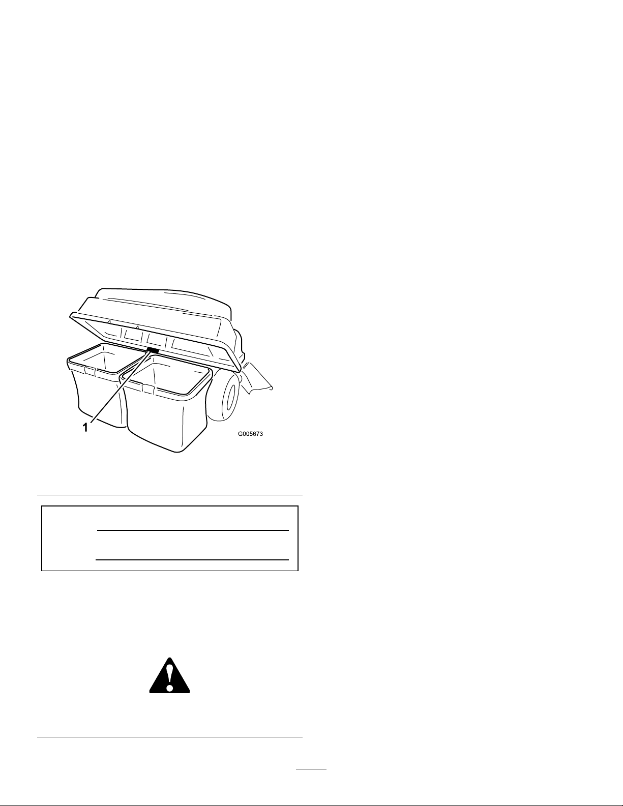
andserialnumbersofyourproductready .Figure1
identiesthelocationofthemodelandserialnumbers
ontheproduct.Writethenumbersinthespace
provided.
Figure1
1.Modelandserialnumberlocation
Introduction.................................................................2
Safety...........................................................................3
SafetyandInstructionalDecals.............................3
Setup............................................................................4
1InstallingtheWeight..........................................5
2InstallingtheBaggerFrame................................6
3AssemblingtheBaggerT op................................6
4InstallingtheBaggerTop...................................7
5InstallingtheChuteOn42InchDecks................8
6InstallingtheChuteon50inchDecks...............10
7InstallingtheDischargeTube...........................11
Operation...................................................................12
EmptyingtheGrassBags....................................12
ClearingObstructionsfromtheBagger...............12
RemovingtheBagger.........................................13
OperatingTips...................................................13
Maintenance...............................................................15
RecommendedMaintenanceSchedule(s)................15
InspectingtheBaggerAttachment......................15
InspectingtheMowerBlades..............................16
CaringfortheGrassBags...................................16
CleaningtheBaggerAttachment.........................16
Storage.......................................................................16
StoringtheBaggerAttachment...........................16
ModelNo.
SerialNo.
Thismanualidentiespotentialhazardsandhas
safetymessagesidentiedbythesafetyalertsymbol
(Figure2),whichsignalsahazardthatmaycauseserious
injuryordeathifyoudonotfollowtherecommended
precautions.
Figure2
1.Safetyalertsymbol
©2008—TheToro®Company
8111LyndaleAvenueSouth
Bloomington,MN55420
Contactusatwww.Toro.com.
2
PrintedintheUSA.
AllRightsReserved
Safety
Enginescanbecomehotwhentheyare
operating.Severeburnscanoccurfrom
contactinghotsurfaces.
Debris,suchasleaves,grass,orbrushcancatch
re.Areintheengineareacancausepersonal
injuryandpropertydamage.
•Keeptheengineandmuferareafreeof
debrisaccumulation.
Allowengines,especiallythemufer,tocool
beforetouching.
•Takecarewhenopeningthebaggercover
tokeepdebrisfromfallingontotheengine
andmuferarea.
•Allowthemachinetocoolbeforestoringit.
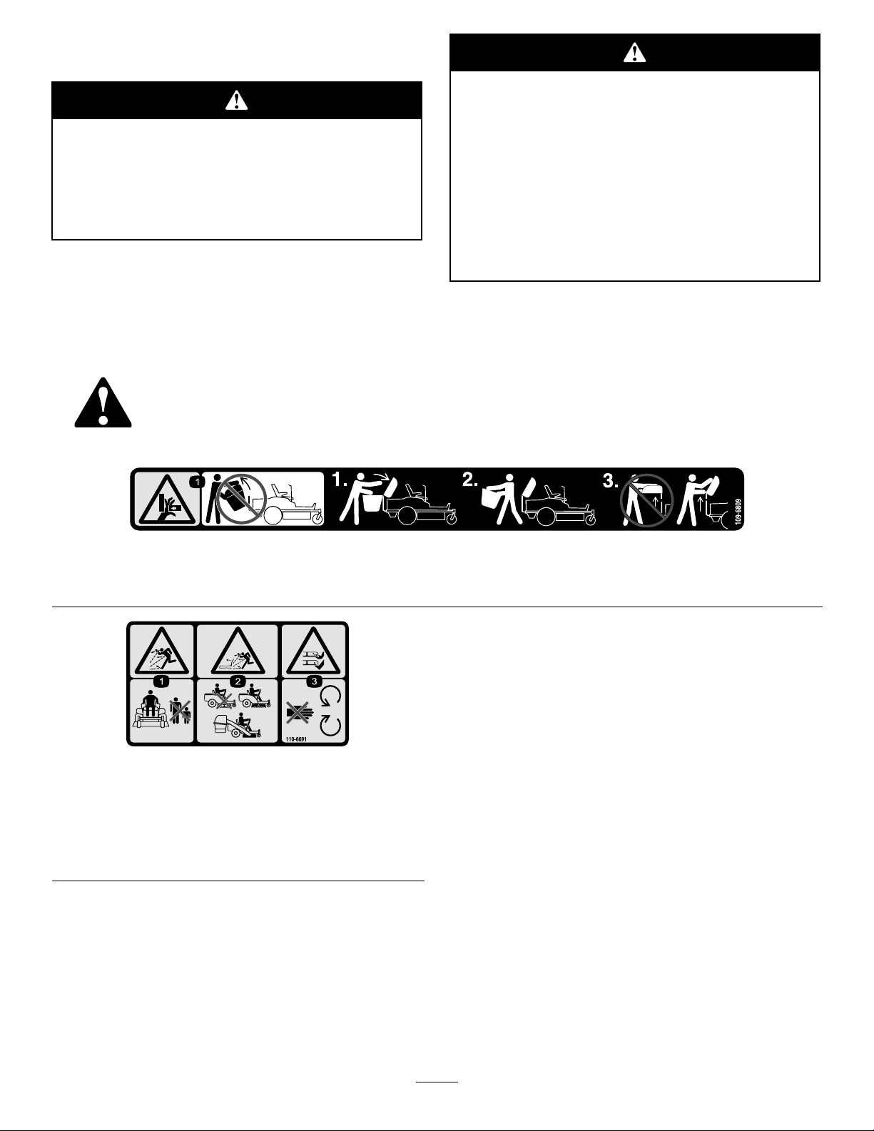
SafetyandInstructionalDecals
Safetydecalsandinstructionsareeasilyvisibletotheoperatorandarelocatednearanyareaof
potentialdanger.Replaceanydecalthatisdamagedorlost.
109-6809
1.Crushinghazardofhand—donotremovethewholebaggerfromthemachine;openthebaggertopandthenremovethebag(s)
fromthebagger .Donotremovethebaggertopwhenitisclosed;openthebaggertopandthenremoveit.
110-6691
1.Thrownobjecthazard—keepbystandersasafedistance
fromthemachine.
2.Thrownobjecthazard,mower—donotoperatethewithout
deectororgrasscollectionsysteminplace.
3.Cutting/dismembermentofhandorfoot—stayawayfrom
movingparts.
3

Setup
LooseParts
Usethechartbelowtoverifythatallpartshavebeenshipped.
ProcedureDescription
1
2
3
4
5
6
7
Qty.
Weight2
U-pin2
Clevispin
Washer6
Hairpin6
BaggerQuickAttachBracket
Clevispin(5/16x2-1/4inch)
Hairpin3
Rod2
Washer2
Baggertop1
Baggerscreen1
Bagger1
GrassBag
Bafecutoff
Chutefor42inchdecks
Bafecutoff
Clipassembly(50indecksonly)
Locknut(5/16inch)
Chutefor50inchdecks
Dischargetube1Installthedischargetube.
2
1
1
2
1
1
1
1
2
1
Installtheweight.
Installthebaggerframe.
Assemblethebaggertop.
Installthebaggertop.
Installthechuteon42inchdecksonly .
Installthechuteanddischargetube.
Use
4
1
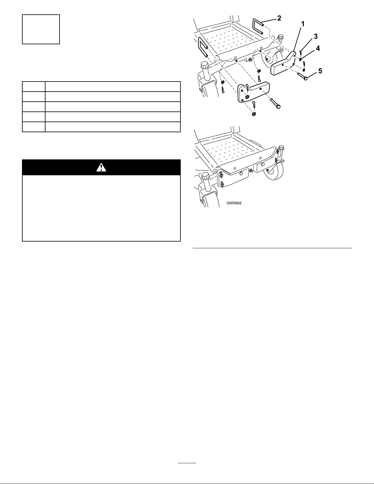
InstallingtheWeight
Partsneededforthisprocedure:
2Weight
2U-pin
2
Clevispin
6Washer
6Hairpin
Procedure
Thebaggerchangestheweightdistributionof
themachine.Operatingthemachinewithout
thefrontweightsmaycauseanunstable
conditionwhichcouldresultinalossofcontrol.
Ensurethefrontweightsareproperlyinstalled
beforeoperatingthemachinewiththebagger
attachment.
Figure3
1.Frontweight4.Washer
2.U-pin
3.Hairpin
5.Clevispin
Attachtheweightstothefrontofthemachineframe
withtwoU-pins,twoclevispins,sixwashers(.531x
1.063),andsixhairpinsasshowninFigure3.
Important:Whenyouremovethetwinbagger,
remembertoremovethefrontweights.
5
2
G005664
1
2
3
4
5
6
7
8
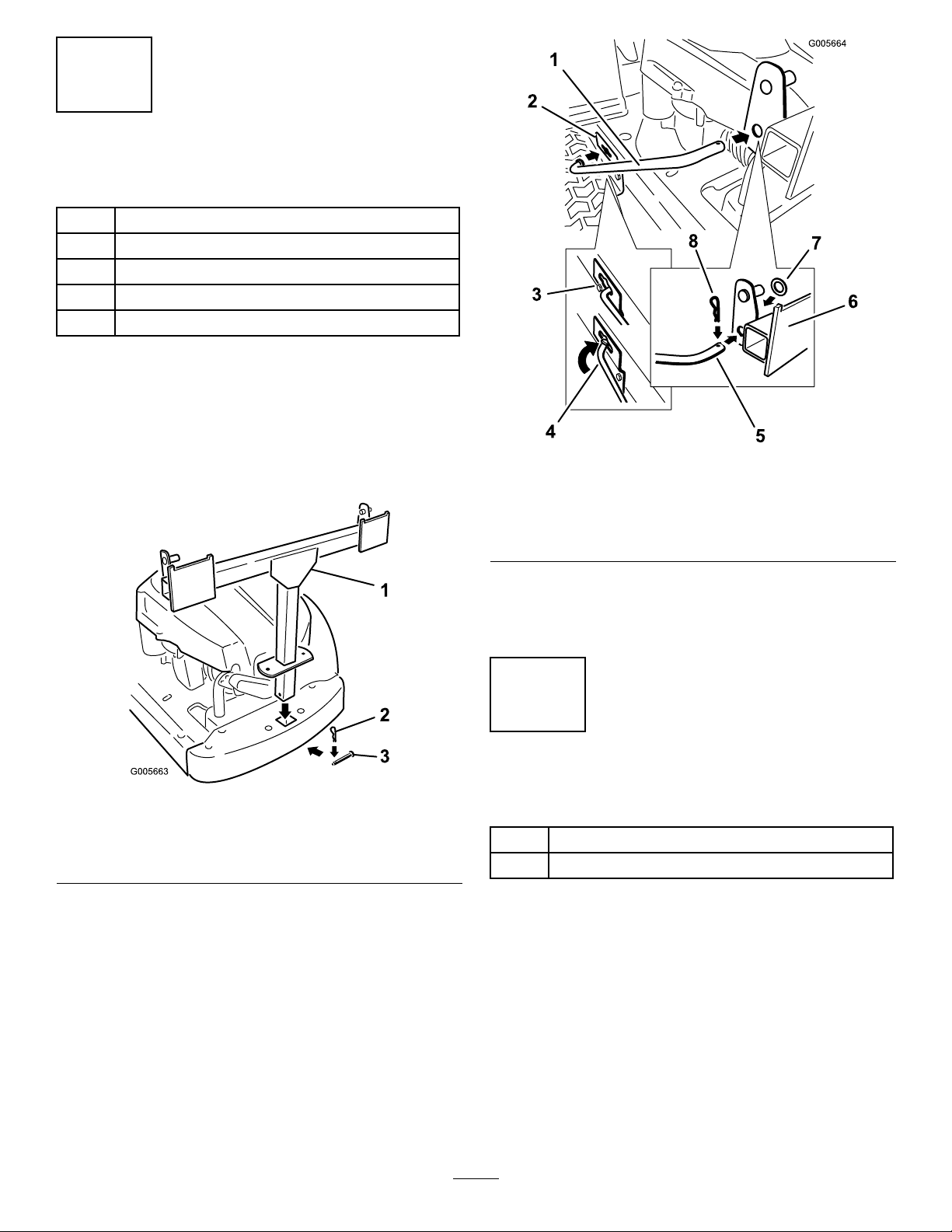
InstallingtheBaggerFrame
Partsneededforthisprocedure:
1
BaggerQuickAttachBracket
1
Clevispin(5/16x2-1/4inch)
3Hairpin
2Rod
2Washer
Procedure
1.Atthebackofthemachine,installthebaggerframe
tothesquareslotintheframe.
2.Securethebaggerframewithaclevispin(5/16x
2-1/4inch)andhairpin(Figure4).
Figure5
1.Rod
2.Slottedbracket6.Baggerframe
3.Openinginslot
4.Flaredendofrod
5.Bentendofrod
7.Washer
8.Hairpin
4.Insertthebentendsoftherodintothebaggerframe
asshowninFigure4.Securethebothendsofthe
rodswithhairpins.
3
AssemblingtheBaggerTop
Figure4
1.Baggerframe3.Clevispin(5/16x2-1/4
2.Hairpin
3.Installtworods,onetoeachsideofthebagger
frame.Locatetheexistingslottedbracketbetween
thereardrivewheelandframe.Startthearedend
oftherodintotheopeningintheslotandslidethe
rodrearward(Figure4).
inch)
Partsneededforthisprocedure:
1Baggertop
1Baggerscreen
Procedure
Turnthebaggertopover.Installthescreenasshownin
Figure6soitslopesdowntowardthecollectionbags.
Makesurethescreenssnapintoplaceandthetabs
engagethebaggertop.
6
 Loading...