

Page 1

50in Recycler® Kit
For TimeCutter® Z4000/5000 Series Riding Mower
Model No. 79312
Installation
Loose Parts
Use the chart below to verify that all parts have been shipped.
Form No. 3357-501 Rev B
Installation Instructions
Step
1
2
3
4
5
Step
1
Preparing the Mower
Description
No parts required
Left bafe
Right bafe
Knob
Curved washer
Kicker plate
Phillips head screw (#8 x 5/8 inch)
Recycling decal
Recycling mower blade
Qty.
–
1
1
4
4
3
6
1
3
Step
2
Installing the Bafes
Use
Prepare the mower.
Install the upper bafe.
Install the kicker plates.
Instal the decal.
Install the blades and mower
No Parts Required
Procedure
1. Stop the engine and remo v e the ignition k ey .
2. R emo v e the mo w er as described in y our
Operator’ s Manual .
3. T ur n the mo w er upside do wn.
4. R emo v e the mo w er blades as described in y our
Operator’ s Manual .
© 2007—The Toro® Company
8111 Lyndale Avenue South
Bloomington, MN 55420
Register at www.Toro.com. Original Instructions (EN)
Parts needed for this step:
1
Left bafe
1
Right bafe
4
Knob
4
Curved washer
Procedure
1. Locate the four holes in the mo w er where the
baffle mounting studs will mount ( Figure 1 )
and remo v e any fasteners from them.
2. Install the left baffle into the dec k securing the
studs on the baffle from the top of the mo w er
using 2 knobs and cur v ed w ashers (cupped
side facing the mo w er) as sho wn in Figure 1
and Figure 2 .
Printed in the USA.
All Rights Reserved
Page 2
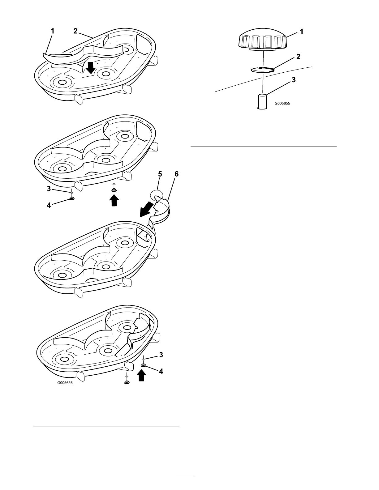
Figure 2
1. Knob 3. Bafe stud coming through
2. Curved washer
the mower
3. Slide the right baffle through the disc harg e
opening and secure it using 2 knobs and cur v ed
w ashers (cupped side facing the mo w er) as
sho wn in Figure 1 and Figure 2 .
Important: Ensur e that the ta b on the
f ar right side of the right baf fle is outside
of the mo w er and is flush with the mo w er
w all.
Figure 1
1. Left bafe 4. Knob
2. Mower
3. Curved washer 6. Right bafe
5. Tab (must remain outside
of the mower)
2
Page 3

Step
Step
3
Installing the Kicker Plates
Parts needed for this step:
3
Kicker plate
6
Phillips head screw (#8 x 5/8 inch)
Procedure
1. Align the three kic k er plates with holes to w ard
the top of the dec k ( Figure 3 ). T he long slope
of the kic k ers m ust be face inw ard.
4
Installing the Decal
Parts needed for this step:
1
Recycling decal
Procedure
Install the decal on left side of mo w er ( Figure 4 ).
Figure 3
1. Mower deck 2. Kicker plate, installed
2. If there are ri v ets bloc king the mounting holes
in the mo w er , drill out the center of eac h ri v et
with a 3/16 inc h (5 mm) drill bit and discard
the ri v et.
3. Secure the plates to the dec k using six Phillips
head screws (#8 x 5/8 inc h). T he screws come
up through the top of the mo w er and into the
plate ( Figure 3 ).
Figure 4
1. Recycler decal 2. Left side of mower
Step
5
Installing the Blades and
Mower
Parts needed for this step:
3
Recycling mower blade
Procedure
1. Install the new recycling mo w er blades as
described in y our Operator’ s Manual .
2. Install the mo w er as described in y our Operator’ s
Manual .
3
Page 4

Operation
Converting to
Side-discharge Operation
W ithout the g rass deflector , discharge
co v er , or complete g rass catcher assembl y
mounted in place, y ou and other s ar e
exposed to blade contact and thr o wn de bris.
Contact with r otating mo w er blade(s) and
thr o wn de bris will cause injur y or death.
• Nev er r emo v e the g rass deflector fr om
the mo w er because the g rass deflector
r outes material do wn to w ard the turf.
If the g rass deflector is ev er dama ged,
r eplace it immediatel y .
• Nev er put y our hands or feet under the
mo w er .
Operating Tips
Selecting the Proper Height-of-Cut
Setting to Suit the Conditions
R emo v e appro ximately one inc h or no more
that 1/3 of the g rass blade when cutting . In
ex ce ptionally lush and dense g rass y ou ma y ha v e
to raise the height-of-cut setting another notc h or
con v er t to side disc harg e or bag ging operations .
Mowing in Extreme Conditions
Air is required to cut and recut g rass clippings in
the mo w er housing, so do not set the height-of-cut
too lo w or totally sur round the housing b y uncut
g rass . Alw a ys ha v e one side of the mo w er housing
free from uncut g rass , allo wing air to be dra wn
into housing . W hen making an initial cut through
the center of the uncut area, operate the mac hine
at a slo w er speed and bac k up if the mo w er star ts
to clog .
• Nev er tr y to clear the discharge ar ea or
mo w er blades unless y ou mo v e the blade
contr ol s witch (PT O) to disenga ge and
tur n the ignition k ey to of f. Also r emo v e
the k ey and pull the wir e of f the spar k
plug(s).
Note: T o use the mo w er in side disc harg e mode ,
only the right baffle m ust be remo v ed. Mounting
hardw are m ust be installed in open holes .
1. Stop the engine and remo v e the ignition k ey .
2. R emo v e the 2 knobs and cur v ed w ashers that
secure the right baffle to the mo w er .
3. R emo v e the right baffle and lo w er the g rass
deflector o v er the disc harg e opening .
Important: Ensur e the mo w er has
a hinged g rass deflector that disper ses
clippings to the side and do wn to w ard the
turf, while in side discharge mode.
4. Install the fasteners y ou remo v ed previously
into the holes in the top of the mo w er to
prev ent flying debris .
T o m ulc h g rass clippings , install the right baffle ,
refer to Installing the Baffles .
Mowing at the Proper Intervals
Under nor mal conditions y ou’ll need to mo w ev er y
4-5 da ys . Ho w ev er , g rass g ro ws at different rates
at different times . T hus , in order to maintain the
same height-of-cut, whic h is a g ood practice , y ou’ll
need to cut more frequently in early spring; as the
g rass g ro wth rate slo ws in mid summer , cut only
ev er y 8-10 da ys . If y ou are unable to mo w for an
extended period due to the w eather conditions or
other reasons , con v er t to side disc harg e or bag ging
options or mo w first with the height-of-cut at a
high lev el; then mo w ag ain 2-3 da ys later with a
lo w er height setting .
Always Mow with Sharp Blades
A shar p blade cuts cleanly and without tearing or
shredding the g rass blade lik e a dull blade . T earing
and shredding causes the g rass to tur n bro wn
at the edg es whic h impairs g ro wth and increases
susce ptibility to disease .
Cleaning After Operating
T o ensure optim um perfor mance , clean the
underside of the mo w er housing . If residue is
allo w ed to build up in mo w er housing, cutting
perfor mance will decrease .
4
 Loading...