

Toro 79305 Operator's Manual

Wheel
FORM NO. 3322–457
Horse
44”
5xi
Lawn and Garden T
Model No. 79305 – 8900001 & Up
V
ac–Bagger
for
ractors
Operator’s Manual
IMPORTANT: Read this manual, and all related equipment manuals,
carefully. They contain information about your safety and the safety of
others. Also become familiar with the controls and their proper use before
you operate the product.
Introduction
We want you to be completely satisfied with your
new product, so feel free to contact your local
Authorized Service Dealer for help with service,
genuine replacement parts, or other information you
may require.
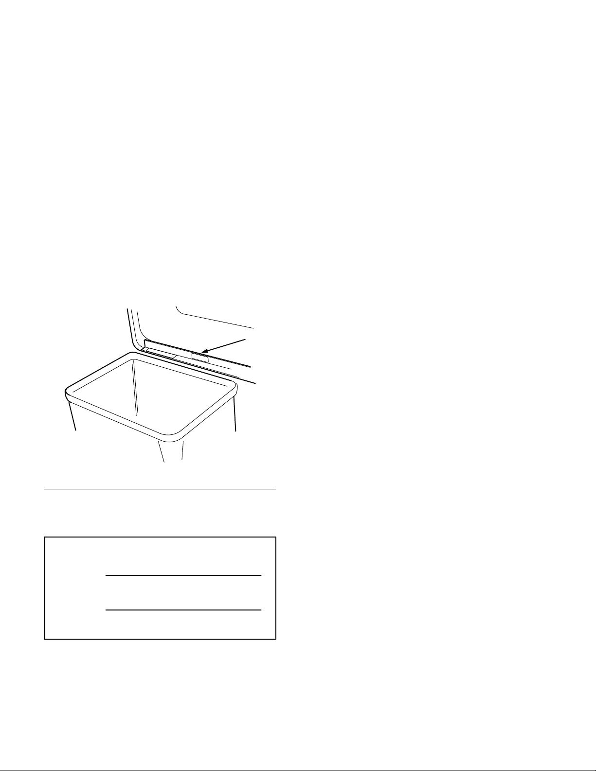
Whenever you contact your Authorized Service
Dealer or the factory, always know the model and
serial numbers of your product. These numbers will
help the Service Dealer or Service Representative
provide exact information about your specific
product. You will find the model and serial number
plate located in a unique place on the product as
shown below
.
1
The warning system in this manual identifies
potential hazards and has special safety messages that
help you and others avoid personal injury, even death.
DANGER, WARNING and CAUTION are signal
words used to identify the level of hazard. However,
regardless of the hazard, be extremely careful.
DANGER signals an extreme hazard that will cause
serious injury or death if the recommended
precautions are not followed.
WARNING signals a hazard that may cause serious
injury or death if the recommended precautions are
not followed.
CAUTION signals a hazard that may cause minor or
moderate injury if the recommended precautions are
not followed.
Two other words are also used to highlight
information. “Important” calls attention to special
mechanical information and “Note” emphasizes
general information worthy of special attention.
1375
1. Model
For your convenience, write the product model and
serial numbers in the space below.
Model No:
Serial No.
and Serial Number Plate
The left and right side of the machine is determined
by sitting on the seat in the normal operator’s
position.
Printed in USA
The TORO Company – 1999

Contents
Page
Safety and Instruction Decals 2.
Installation 3
Loose Parts 3
Preparing the Tractor 5
Preparing the Mower 6
Installing the Vac-Bagger
Removing the Bagger 15
Removing the Vac–Bagger
. . . . . . . . . . . . . . . . . . . . . . . . . . . . .
. . . . . . . . . . . . . . . . . . . . . . . . .
onto the Tractor 11
from the Tractor 18
. . . . . . . . . . . . . . . . . . .
. . . . . . . . . . . . . . . . . . .
. . . . . . . . . . . . .
. . . . . . . . . . . . . . . . .
. . . . . . . . . . . . . . . . .
. . . . . . . . . . . . . . . . .
Page
Operation 23
Maintenance 26
. . . . . . . . . . . . . . . . . . . . . . . . . . . . . .
Using the Full Bag Tester 23
Emptying the Grass Bags 23
Clearing Obstructions
from the Bagger 24
Operating and Bagging Tips 24
. . . . . . . . . . . . . . . . . . . . . . . . . . . .
Inspecting the Bagger Attachment 26
Inspecting the Mower Blades26. . . . . . . . . . .
Caring for the Grass Bags 26
Cleaning the Bagger Attachment 26
Storing the Bagger Attachment 27
. . . . . . . . . . . . . .
. . . . . . . . . . . . . .
. . . . . . . . . . . . . . . . . . .
. . . . . . . . . . .
. . . . . . .
. . . . . . . . . . . . .
. . . . . . . .
. . . . . . . . .
1
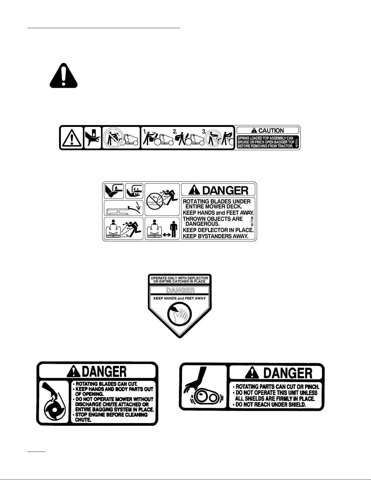
Safety
Safety
and Instruction Decals
Safety decals and instructions are easily visible to the operator and are located near
any area of potential danger. Replace any decal that is damaged or lost.
INSIDE EDGE OF BAGGER T
ART NO. 92–71
(P
ON T
OP OF DECK (LEFT SIDE)
(P
ART NO. 92–7108)
OP
13)
MOLDED INT
O BEL
T SHIELD
MOLDED INT
O BEL
T SHIELD
MOLDED INT
O BEL
T SHIELD
2

Installation
Loose
Parts
Note: Use the chart below to identify parts used for assembly.
DESCRIPTION QTY. USE
J–pin
Cotter pin
Bagger hitch
Bolt 3/8–16 x 1” (25 mm)
Nut 3/8”
Carriage bolt 3/8–16 x 3/4” (19 mm)
Washer 1/2” (13 mm)
Locknut 3/8”
Blade (hi-lift)
Grass baf
Carriage bolt 5/16–18 x 7/8” (22 mm)
Carriage bolt 5/16–18 x 1/2” (13 mm)
Locknut 5/16”
fle-front
1
1
1
4
4
2
2
2
3
1
3
1
3
Prepare tractor lift arm
Mount bagger hitch
Install in open slots when Recycler baffles are
removed
Replace standard lift blades
Install front grass baf
fle
Locknut (thin) 5/16”
Grass baf
Grass ring
Bolt 1/4–20 x 3/4” (19 mm)
Locknut 1/4”
Carriage bolt 5/16–18 x 7/8” (22 mm)
Carriage bolt 5/16–18 x 2-1/2” (64 mm)
Latch tube
Locknut 5/16”
Counterweight
Cover plate
Bolt 3/8–16 x 2–1/4” (57 mm)
Flat washer 3/8” (10 mm)
Locknut 3/8”
Danger decal
Bolt 3/8–16 x 3/4” (19 mm)
Locknut 3/8”
fle-rear
1
1
1
2
2
3
1
1
4
1
1
2
4
2
1
2
2
Install rear grass baf
Install counterweight
Install in open holes when counterweight is
removed
fle and grass ring
3

Installation
DESCRIPTION USEQTY.
Cover
Indicator rod
Handle
Jam nut 1/4”
Clips
Screw 1/4–20 x 3/4” (19 mm)
Locknut 1/4”
Frame assembly
Pivot support
Pivot bracket
Spacer tube
Carriage bolt 5/16–18 x 4-1/2” (1
Bolt 5/16–18 x 7/8” (19 mm)
Washer 5/16” (8 mm)
Locknut 5/16”
Pulley
Belt
14 mm)
1
1
1
1
2
2
4
1
1
1
1
1
1
2
4
1
1
Assemble the bagger
Install blower pivot support
Blower assembly
Blower belt cover
Washer
Knobs
Quick-attach bracket
Hairpin cotter
Grass bags
Discharge tube
Operator’
s Manual
1
1
4
2
1
2
2
1
1
Install the blower
Install the bagger assembly and discharge tube
Read before operating
4
Installation
Preparing
the T
ractor
Install New J–Pin
Before you can install the bagger, you must first
install a bagger–compatible J–pin in the attachment
lift arm on the right side of the tractor. This is most
easily done on a level concrete surface. Rougher dirt
or lawn surfaces make installation more difficult.
1. Remove the mower; refer to Mower Operator’s
Manual for instructions.
2. Start the tractor, set the parking brake, lower the
attachment lift, and turn the ignition key to
“STOP” to stop the engine. Remove the ignition
key.
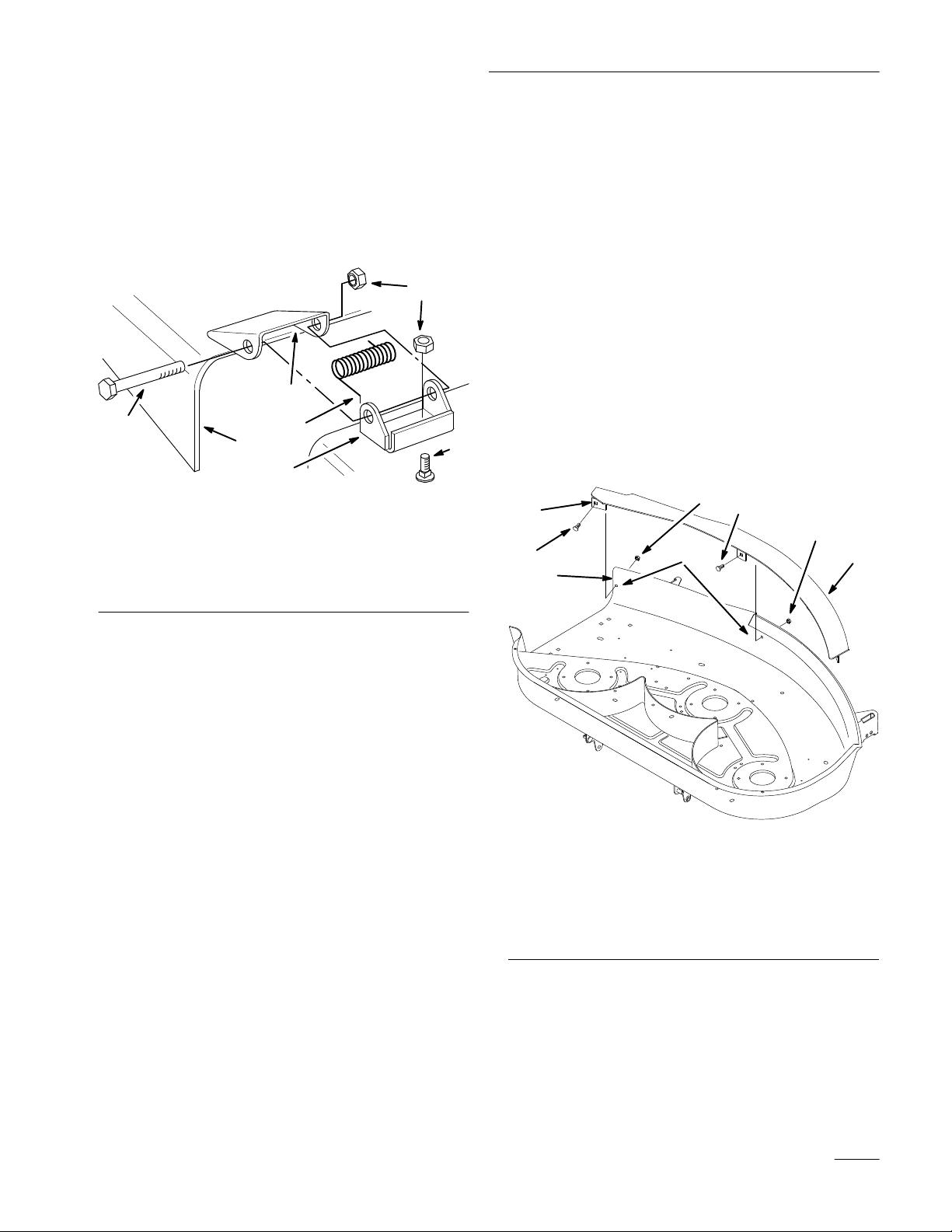
3. Remove the cotter pin from the J–pin on the
right side of the tractor (Fig. 1). Slide the
washer and spring from the J–pin, then remove
the J–pin from the attachment lift arm.
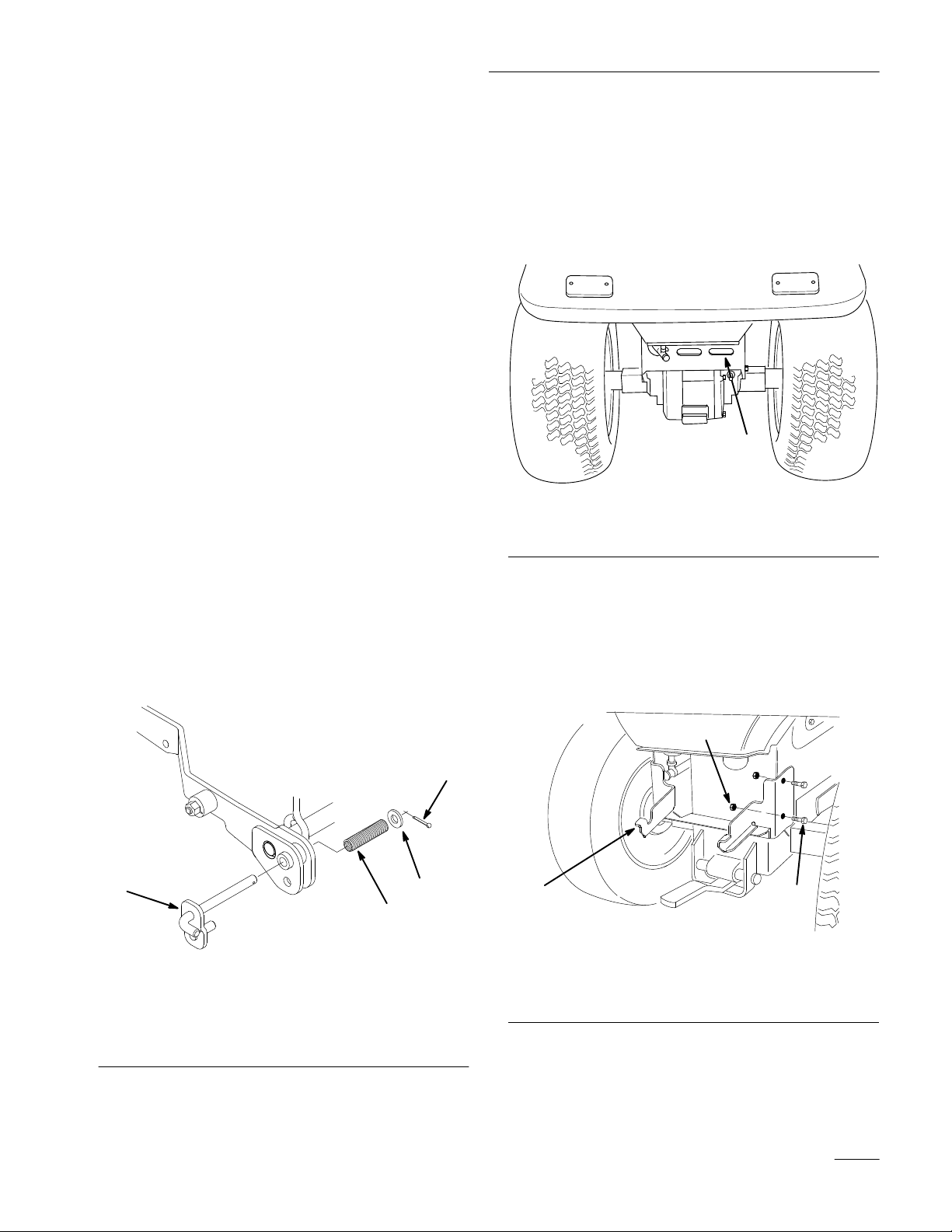
Remove the Transaxle Cover
Remove the transaxle cover from the back of the
tractor (Fig. 2).
Note: Save all parts and hardware for use
when installing the transaxle cover.
1
Figure 2
1. Rear
transaxle cover
m–3436
4. Install the new, bagger–compatible J–pin into the
location from which you removed the old pin.
Slide the washer and spring onto the J–pin.
Insert a new cotter pin and bend the ends of the
pin to secure the assembly (Fig. 1).
4
1
1. Bagger
2. Spring
Figure 1
Right side of tractor shown
J–pin
3. Washer
4.
Cotter pin
3
2
m–3595
Mount the Vac Bagger Hitch to the
Tractor
Install the vac bagger hitch to the tractor with 4 bolts
and nuts (Fig. 3).
3
1
1. Bagger
2.
hitch
Bolt 3/8 x 1” (25 mm)
Figure 3
3.
Nut 3/8”
2
m–3636
5
Installation
Preparing
the Mower
Remove the Recycling Baffles
If you have a recycling mower deck, you must
remove the recycling baffles to use the vac bagger.
1. Thoroughly clean the mower.
2. Remove the knobs and washers from the right
side baffle and the nuts and washers from the left
side baffle (Fig. 4). Lift the baffles from the
deck.
3
2
5
7
3
5
7
POTENTIAL HAZARD
• Open holes in the mower expose you and
others to thrown debris.
WHAT CAN HAPPEN
• Debris thrown out of holes in the mower
can cause injury.
HOW TO AV
OID THE HAZARD
• Never operate the mower without hardware
mounted in all holes in the mower.
• Install hardware in the mounting holes
when the recycle baffle is removed.
1
3. Install (2) 3/8–16 x 3/4” (19 mm) carriage bolts
(from the underside of the mower), (2) 1/2” (13
mm) washers, and (2) 3/8” locknuts in the (2)
open slotted holes of the mower shown in
Figure 4.
4
6
Figure 4
1. Baffle
2. Baf
3.
4. Belleville
left side
fle right side
Bolt, 5/16 x 1-1/4” (32
mm)
washer—concave side
toward deck surface
5.
Locknut 5/16”
6. Knob
7.
Slotted hole
Note: Save hardware for use when installing
the baffles.
4
5
m–3485
Install Hi-lift Blades
1. Install the hi-lift blades from the bagger in place
of the standard blades. Refer to Mower
Operator’
Note: The hi–lift blades are also used for
s Manual; Cutting Blade.
Recycler mowers.
6
Installation
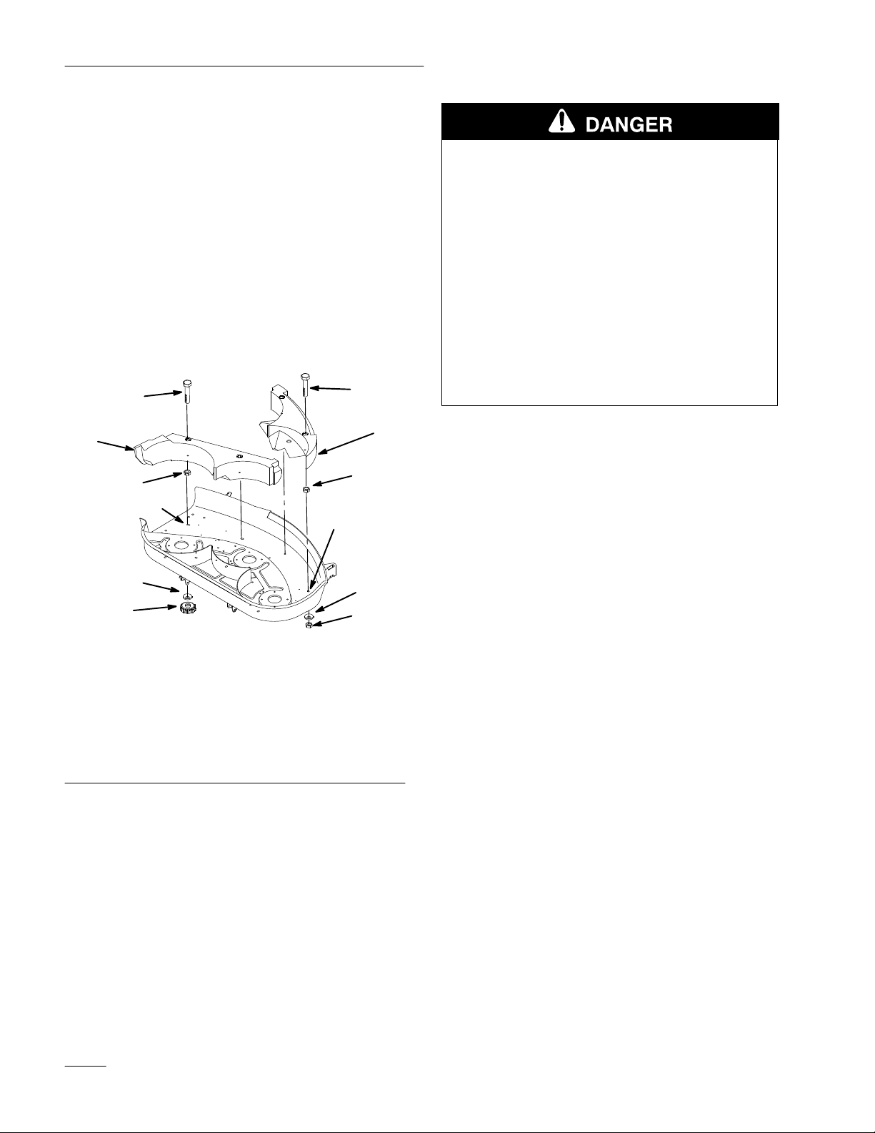
Remove the Discharge Chute
1. Remove the discharge chute and mounting
brackets from the mower (Fig. 5).
Note: Save all parts and hardware for use
when installing the discharge chute.
3
5
1. Bracket
2. Spring
3.
Space for spring
4.
Discharge chute
hook end
4
1
Figure 5
2
5. Bolt
6. Locknut
7.
Carriage bolt
m–3484
Install the Grass Baffles
1. Place the front grass baffle inside the front edge
of the mower. The baffle plate should rest on the
front edge of the mower. The right tab on the
baffle should extend 1/8” (3 mm) outside of the
right edge of the mower (Fig. 6). Use a clamp to
hold the baffle in place.
6
7
2. Mark where the holes in the baffle are and
remove the clamp and grass baffle. Drill (4)
11/32” holes (Fig. 6).
3. Install the grass baffle inside the front edge of
the mower using (3) 5/16 x 7/8” (19 mm)
carriage bolts and (3) 5/16” locknuts. At the
right side use the 5/16 x 1/2” (13 mm) carriage
bolt and thin 5/16” locknut (Fig. 6).
6
7
5
2
8
3
4
1
1. Front
2.
3.
4.
grass baf
Drill 1
1/32” hole
Carriage bolt, 5/16 x 7/8”
(19 mm)
Locknut ,5/16”
fle
Figure 6
5.
Carriage bolt, 5/16 x 1/2”
(13 mm)
6.
Locknut (thin), 5/16”
7.
Right tab on baf
8.
Right edge of mower
m–3634
fle
7
Installation
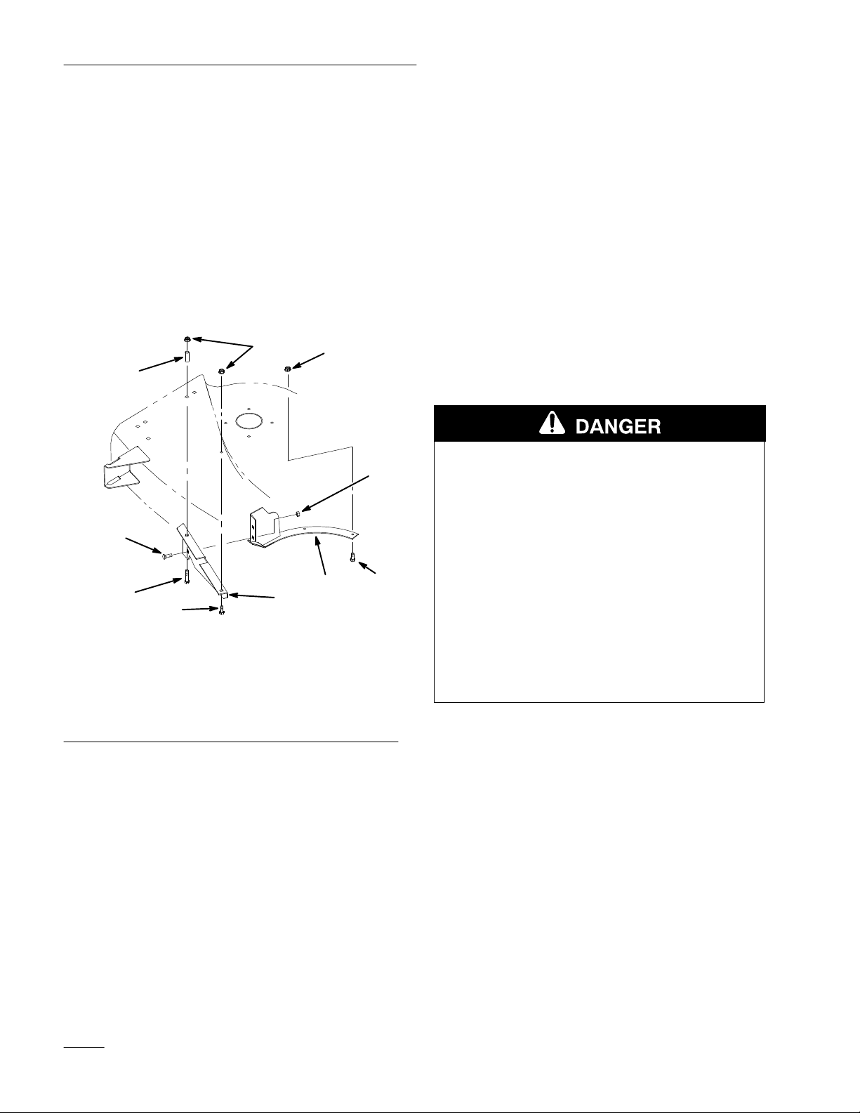
4. Attach the rear grass baffle to the grass ring with
(2) 5/16 x 7/8” (22 mm) carriage bolts and (2)
5/16” locknuts (Fig. 7).
5. Install the rear grass baffle and grass ring inside
the discharge chute area. Secure the rear grass
baffle to the mower with a 5/16 x 7/8” (22 mm)
carriage bolt and a 5/16 x 2–1/2” (64 mm)
carriage bolt. Add the latch tube above the deck
and secure with (2) 5/16” locknuts. Secure the
grass ring to the mower with (2) 1/4 x 3/4” (19
mm) bolts and (2) 1/4” locknuts (Fig. 7).
5
3
8
5
Install the Mower Deck Counterweight
(Use these instructions for decks with
washout port)
If your mower deck has a washout port (Fig. 9), use
these instructions for mounting the counterweight. If
there is no washout port, skip this section and install
the counterweight per the next section.
The washout port must be removed to install the
vac–bagger counterweight. This removal leaves open
holes in the top of the mower deck.
The cover plate, included in loose parts, prevents
debris from being thrown out of the open holes in the
mower deck.
POTENTIAL HAZARD
• Open holes in the mower expose you and
others to thrown debris.
4
6
1. Rear
2.
3.
4.
grass baf
Grass ring
Latch tube
Carriage bolt, 5/16 x 7/8”
(22 mm)
fle
4
Figure 7
1
5.
Locknut 5/16
6.
Carriage bolt, 5/16 x
2-1/2” (64 mm)
7. Screw
8.
Locknut 1/4”
2
m–3637
, 1/4 x 3/4” (19 mm)
6. Rotate the blades to make sure they do not hit
the baffles or grass ring. Adjust the baf
fles as
required so the blades do not hit.
WHAT CAN HAPPEN
• Debris thrown out of holes in the mower
can cause injury.
7
HOW TO AV
OID THE HAZARD
• Never operate mower without hardware
mounted in all holes in mower.
• Install hardware in mounting holes when
the washout port is removed.
Installation
1. Remove the two bolts, flat washers and nuts
holding the washout port to the deck and remove
the washout port (Fig. 8). Save the washout port
and the bolts, nuts and washers for reinstallation
when removing the counterweight.
8
 Loading...