

Page 1

FORM NO. 3318–252
48” Snow Blade
for
Lawn & Garden Tractors
Model No. 79252 – 6900001 & Up
Model No. 99251 – 6900001 & Up
Model No. 9861907 – T6S0001 & Up
Operator’s Manual
IMPORTANT: Read this manual carefully. It contains information about your
safety and the safety of others. Also become familiar with the controls and
their proper use before you operate the product.
Page 2
Introduction
We want you to be completely satisfied with your
new product, so feel free to contact your local
Authorized Service Dealer for help with service,
genuine replacement parts, or other information you
may require.
Whenever you contact your Authorized Service
Dealer or the factory, always know the model and
serial numbers of your product. These numbers will
help the Service Dealer or Service Representative
provide exact information about your specific
product. You will find the model and serial number
plate located in a unique place on the product as
shown below.
1
1237a
The warning system in this manual identifies
potential hazards and has special safety messages that
help you and others avoid personal injury, even death.
DANGER, WARNING and CAUTION are signal
words used to identify the level of hazard. However,
regardless of the hazard, be extremely careful.
DANGER signals an extreme hazard that will cause
serious injury or death if the recommended
precautions are not followed.
WARNING signals a hazard that may cause serious
injury or death if the recommended precautions are
not followed.
CAUTION signals a hazard that may cause minor or
moderate injury if the recommended precautions are
not followed.
Two other words are also used to highlight
information. “Important” calls attention to special
mechanical information and “Note” emphasizes
general information worthy of special attention.
The left and right side of the machine is determined
by sitting on the seat in the normal operator’s
position.
1. Model and Serial Number Plate
For your convenience, write the product model and
serial numbers in the space below.
Model No:
Serial No.
Printed in USA
Page 3

Contents
Installation 2. . . . . . . . . . . . . . . . . . . . . . . . . . . . .
Loose Parts 2. . . . . . . . . . . . . . . . . . . . . . . . .
Assemble Blade 4. . . . . . . . . . . . . . . . . . . . .
Tractor Set-Up 6. . . . . . . . . . . . . . . . . . . . . .
Installing Snow Blade to Tractor 7. . . . . . . .
Removing the Snow Blade 8. . . . . . . . . . . . .
Operation 10. . . . . . . . . . . . . . . . . . . . . . . . . . . . . .
Attachment Power Lift 10. . . . . . . . . . . . . . . .
Attachment Lift Lever 11. . . . . . . . . . . . . . . .
Page
Page
Adjusting Dial-A-Height 11. . . . . . . . . . . . . .
Adjusting Blade Index 12. . . . . . . . . . . . . . . .
Adjusting Blade Trip Springs 12. . . . . . . . . .
Tips for Using Snow Blade 13. . . . . . . . . . . .
Maintenance 14. . . . . . . . . . . . . . . . . . . . . . . . . . . .
Service Interval Chart 14. . . . . . . . . . . . . . . .
Greasing and Lubrication 15. . . . . . . . . . . . . .
Reversing the Scraper Blade 16. . . . . . . . . . .
Storage 16. . . . . . . . . . . . . . . . . . . . . . . . . . . . . . . .
1
Page 4

Installation
Loose Parts
Note: Use the chart below to identify parts used for assembly.
DESCRIPTION QTY. USE
Channel assembly
Tip spring
Rod
Cotter pin
Hairpin cotter
Bolt 3/4–16 x 3/4”
Nut 3/4”
Index rod
Index plate
Bolt 3/8–16 x 1”
Washer 3/8”
Lock nut 3/8”
Index lever
Bolt 1/2–13 x 1”
Nut 1/2”
Eyebolt
Eyelet
1
2
3
4
2
1
1
1
1
1
1
1
1
1
1
1
1
Assemble blade to channel and frame
Assemble index plate to frame
Washer #10
Lock nut #10
Control rod
Washer 1/2”
Hairpin cotter
Cotter pin
2
2
3
1
1
1
1
Assemble index handle to frame
Page 5

DESCRIPTION USEQTY.
Installation
Lift weldment
Plate
Bolt 3/8–16 x 1”
Lock nut 3/8”
Washer 5/8”
Cotter pin
Lift rod
Hitch assembly
Carriage bolt 3/8–16 x 1’
Washer 3/8”
Lock nut 3/8”
Rear mounting plate
Blade bracket
Bolt 1/2–13 x 1-1/4”
Lock nut 1/2”
Latch lever
Washer 3/8”
1
2
4
4
3
3
1
1
4
4
4
1
1
3
5
2
2
Mount lift assembly to frame
Install front hitch
Assemble rear hitch
Carriage bolt 3/8–16 x 1-1/4”
Spindle stop
Self tapping bolt 5/16–18 x 3/4”
2
1
Install steering spindle stop
1
3
Page 6
Installation
Installation
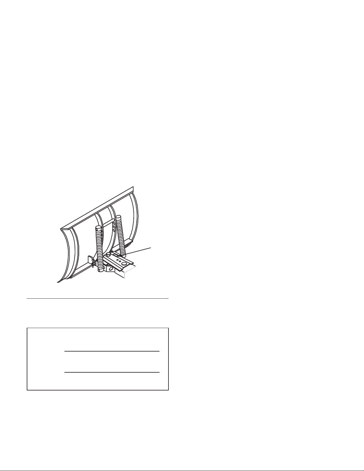
Assemble Blade
1. Attach channel assemble and blade trip springs
to blade with rods and hairpin cotters and cotter
pins (Fig. 1).
2. Apply liberal amount of general purpose grease
to pivot area of frame and channel (Fig. 1) and
attach with 3/4 x 3/4” bolt and 3/4” nut.
IMPORTANT: Do not tighten nut and bolt
excessively to cause binding on channel
weldment as it pivots side-to-side.
2
8
3
4
5
1
7
8
5
4
6
1469a
3. Place index rod through hole in frame and slide
into hole in index pin (Fig. 2).
4. Hook index rod into front hole of index plate and
attach to frame with 3/8 x 1” bolt, 3/8” washer
and 3/8” lock nut (Fig. 2).
IMPORTANT: Do not tighten nut and bolt
excessively to cause binding of lever at bracket.
5
6
Figure 2
1. Index rod
2. Index pin
3. Front hole of index plate
4
3
1
2
2287
4. Bolt 3/8 x 1”
5. Washer 3/8”
6. Lock nut 3/8”
1. Channel Assembly
2. Trip spring
3. Rod
4. Cotter pin
Figure 1
5. Grease here
6. Bolt 3/4 x 3/4”
7. Nut 3/4”
8. Hairpin cotter
4
Page 7

5. Attach index lever to frame bracket with 1/2 x 1”
bolt and 1/2” nut (Fig. 3).
IMPORTANT: Do not tighten nut and bolt
excessively to cause binding of lever at bracket.
Installation
2
6. Install eye bolt and eyelets with (2) #10 washers
and (2) #10 lock nuts(Fig. 3).
7. Thread jam nut and turnbuckle onto cable and
hook into handle lever(Fig. 3).
8. Route cable through eyebolt and eyelet and
attach Z end to back hole of index plate (Fig. 3).
9. Adjust turnbuckle so the index pin is pulled out
of channel when the release lever is squeezed,
for easy side-to-side movement (Fig. 3). Tighten
jam nut securely.
10. Attach one end of control rod to index lever with
1/2” washer and hairpin cotter. (Fig. 3).
8
4
11
10
6
1
4
5
9
3
1
1467
Figure 4
1. Control r o d
2. Plate
3. Cotter pin
12. Place front lift weldment between frame and
attach captured plate to frame with (2) 3/8 x 1”
bolts and (2) 3/8” lock nuts (Fig. 5).
13. Slide remaining plate over shaft and secure to
frame with (2) 3/8 x 1”bolts and (2) 3/8”lock
nuts. Secure lift assembly shaft to plate with
5/8” washer and cotter pin (Fig. 5).
14. Attach lift rod to lift weldment and secure with
5/8” washer and cotter pin (Fig. 5).
8
7
7
3
2288
14
12132
Figure 3
1. Index lever
2. Bolt 1/2 x 1”
3. Nut 1/2”
4. Cable Z end
5. Eyelet
6. Eyebolt
7. Lock nut and washer #10
8. Handle lever
9. Back hole of index plate
10. Turnbuckle
11. Jam nut
12. Control rod
13. Washer 1/2”
14. Hairpin cotter
11. Insert control rod, end with welded washer, thru
hole in bottom plate of channel weldment
(Fig. 4). Secure with cotter pin, between the
plates.
3
5
4
1. Lift weldment
2. Captured plate
3. Bolt 3/8 x 1”
4. Lock nut 3/8”
8
Figure 5
4
5. Plate
6. Lift rod
7. Washer 5/8”
8. Cotter pin
1
2
3
6
7
1246b
5
Page 8

Installation
Tractor Set-Up
1. Remove E–ring and all except one thick washer
from tractor front axle pivot pin. Discard unused
washers. (Fig. 6). Remove muffler shield.
2. Install (4) 3/8 x 1 carriage bolts into keyhole
slots in axle bracket. Install muffler shield and
place front hitch onto the tractor securing with
(4) 3/8” washers, (4) 3/8” lock nuts and
previously removed E-ring (Fig. 6).
6
7
1
5
3
2
4
1287
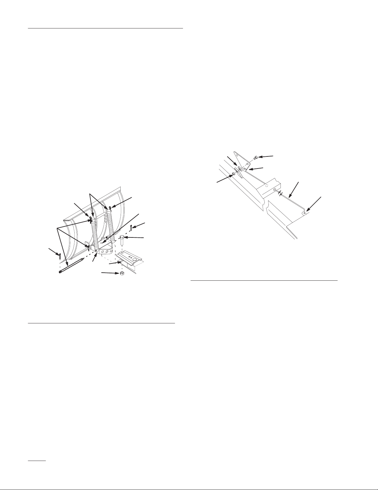
3. Assemble rear mounting plate and blade bracket
with (2) 1/2 x 1-1/4” bolts (heads toward the
rear) and (2) 1/2” lock nuts through holes in
vertical plates (Fig. 7).
4. For blade use latch levers must be installed onto
the blade bracket (Fig. 7). If necessary remove
latch levers from rear mounting plate and move
to the blade bracket. Secure with previously
removed hardware (Fig. 7).
IMPORTANT: Do not tighten nut and bolt
excessively to cause binding of levers at bracket.
5
2
4
6
8
7
1. E-ring
2. Thick Washer (existing)
3. Axle pivot
4. Front hitch
Figure 6
5. Carriage bolt 3/8 x 1”
6. Washer 3/8”
7. Lock nut 3/8”
1. Rear mounting plate
2. Blade bracket
3. Bolt 1/2 x 1-1/4”
4. Lock nut 1/2”
Figure 7
31
1466
5. Carriage bolt 3/8 x 1-1/4”
6. Washer 3/8”
7. Latch lever
8. Lock nut 3/8’
6
Page 9

Installation
5. Install rear mounting plate\blade bracket
assembly under and inside rear frame member
with short tongue rearward (Fig. 8). Secure with
(3) 1/2 x 1-1/4” bolts and (3) 1/2”lock nuts at
holes in frame side members and tongue forward
hole (Fig. 8).
2
2
Figure 8
1. Plate\blade bracket
assembly
3
2. Bolt 1/2 x 1-1/4”
3. Lock nut 1/2”
1
1478
3
6. Install steering spindle stops in front of the rear
tab on front wheel spindles (Fig. 9). Align so
stops contact the axle during tight turns and
wheels do not contact the frame. Secure with
5/16 x 3/4”self tapping bolt (Fig. 9).
Installing Snow Blade to
Tractor
1. Position snow blade on a level surface with
space behind for tractor.
2. Remove bolt securing index lever to frame and
lay lever next to frame.
3. Open front hitch on tractor and park the tractor
behind snow blade, with frame between the front
wheels. Disengage the power take off (PTO), set
the parking brake, and turn the ignition key to
“OFF” to stop the engine. Remove the key.
4. Slide frame under tractor and center between rear
latches. Open latch levers and lift frame into
position. (Fig. 10).
5. Secure latch levers with clevis pins and hairpin
cotters (Fig. 10).
6. Attach index lever to frame with previously
removed hardware.
2
1
3
1. Steering wheel stop
2. Self tapping bolt
5/16 x 3/4”
Figure 9
3. Spindle stop
1471
3
4
1
Figure 10
1. Frame mount
2. Latch lever
2
3. Clevis pin
4. Hairpin cotter
7. Slide front lift arm of blade into tractor front
hitch. Close and lock front hitch (Fig. 11).
1470
7
Page 10

Installation
2
1
1246a
Figure 11
1. Lift arm 2. Front hitch
8. Set Dial-a-Height to the Mounting Position, and
lower attachment lift all the way; refer to Setting
Height-of-Cut.
9. Position lift plate notch around left side lift rod
and slide lift plate onto attachment lift arm
(Fig. 12). Secure with hairpin cotter at lift arm.
Removing the Snow Blade
Note: Save all hardware, rods, washers and
hairpin cotters for reuse when
installing blade.
1. Park the machine on a level surface, disengage
the power take off (PTO), set the parking brake,
and turn the ignition key to “OFF” to stop the
engine. Remove the key.
2. Raise attachment lift to the transport position .
Turn the Dial-a-Height knob counterclockwise,
all the way, and lower the attachment lift lever to
the mounting position; refer to Lowering
Attachments.
3. Remove hairpin cotter and 5/8” washer from
trunnion at lift plate (Fig. 13).
4. Remove hairpin cotter and slide lift plate off
attachment lift (Fig. 13).
10. Connect lift rod trunnion at one of the holes in
the attachment lift plate with 5/8” washer and
hairpin cotter (Fig. 12).
Note: Low hole provides maximum blade
lift, but requires the greatest lift effort.
Top hole requires less lift effort, but
has lower lift height.
1
4
2
1. Notch
2. Lift plate
3. Lift arm
5
6
Figure 12
4. Lift rod trunnion
5. Washer 5/8”
6. Hairpin cotter
3
6
1265
1. Hairpin cotter
2. Washer 5/8”
3
1
4
2
1
Figure 13
3. Trunnion
4. Lift plate
1265
8
Page 11

5. Remove hairpin cotters and clevis pins from
latch levers (Fig. 14). Open latch levers and
lower the frame (Fig. 14).
1
Installation
24
3
1470
Figure 14
1. Clevis pin
2. Hairpin cotter
3. Latch lever
4. Frame
6. Push in on the front hitch release rod to open the
hitch and remove blade lift arm (Fig. 15).
7. Remove hairpin cotter and clevis pin from idler
pulley assembly, unhook and remove (Fig. 15).
2
1
3
1246a
Figure 15
1. Release ro d
2. Hitch
3. Lift arm
Note: Save all hardware, rods, washers and
hairpin cotters for reuse when
installing snow blade.
9
Page 12

Operation
POTENTIAL HAZARD
• Hitting fixed objects can cause the tractor
to stop abruptly.
WHAT CAN HAPPEN
• Stopping abruptly can cause loss of control,
equipment damage and personal injury.
HOW TO AVOID THE HAZARD
• Travel at a safe, slow speed.
• Check area to be plowed and mark all fixed
objects so they can be avoided.
Attachment Power Lift
The attachment power lift (optional on some models)
(Fig. 16) is used to raise and lower attachments.
2
3
1. Key
2. Lift switch UP
1
2266
Figure 16
3. Lift switch DOWN
Raising Attachments
1. Turn key to the “ON” or “RUN” position
(Fig. 16).
2. Push the lift switch in the “UP” direction to raise
the attachment lift (Fig. 16). This will lift and
hold the attachment in the up, or raised position.
Lowering Attachments
1. Turn key to the “ON” or “RUN” position
(Fig. 16).
2. Push the lift switch in the “DOWN” direction to
lower the attachment lift (Fig. 16). This will
lower the attachment lift.
10
Page 13

Operation
Attachment Lift Lever
The attachment lift lever (Fig. 17) is used to raise and
lower various attachments.
Raising Attachments
1. Depress the clutch and/or brake pedal(s) to stop
the machine.
2. Pull attachment lift lever rearward until latch
locks. In this position the lift will hold the
attachment in the up, or raised position.
Lowering Attachments
1. Depress the clutch and/or brake pedal(s) to stop
the machine.
2. Pull attachment lift lever rearward, to release lift
pressure, and push the button on top to release
the latch. Move lift lever forward to lower
attachment.
Adjusting Dial-A-Height
The Dial-A-Height control (Fig. 17) is used to limit
the downward travel of the attachment. The
Dial-A-Height knob is rotated to change the location
of this stop, up or down.
1. Raise the attachment lift lever: Refer to Raising
Attachments. In the raised position the
Dial-A-Height knob (Fig. 17) can be rotated to
change the stop location. Turn clockwise to raise
and counterclockwise to lower the height of the
attachment.
2. The Dial-A-Height indicator (Fig. 17) will show
the change, high to low, in attachment lift height
as adjustment is made.
2
1
1. Lift lever
2. Button
3. Dial-A-Height
Figure 17
4. Indicator
5. High
6. Mounting position
3
5
4
6
1205
11
Page 14

Operation
Adjusting Blade Index
The blade can be indexed side to side, in 5 positions.
The direction is controlled by the handle on the right
frame (Fig. 18).
1. Squeeze the release lever toward the handle
(Fig. 18).
2. Push or pull lever to change index position and
release lever. Index pin must snap into hole in
channel to retain position.
2
1
1477
Figure 18
1. Handle 2. Release lever
Adjusting Blade Trip Springs
The blade trip springs can be mounted in 4 positions.
The top hole provides greatest scraping pressure and
the lower hole least scraping pressure (Fig. 19).
1. Remove hairpin cotter and slide rod out from
blade and springs (Fig. 19).
2. Slide rod through springs and new hole position
in blade (Fig. 19).
2
1. Hairpin cotter
2. Rod
4
Figure 19
3. Spring
4. T op hole
1
3
1237
12
Page 15

Tips for Using Snow Blade
Remove snow as soon as possible after it falls. This
produces best snow removal results.
Snow is generally removed from driveway by making
one pass down the center and then plowing snow to
either side on successive passes.
If tractor looses traction when using snow blade,
wheel weights and tire chains may be available from
your dealer.
Blade trip springs can be adjusted for scraping
aggressiveness and surface conditions. Second hole
from the top is recommended for snow. Refer to
adjusting blade trip springs.
Operation
13
Page 16

Maintenance
Service Interval Chart
Each
Service Operation
Grease–Channel pivot X X X
Oil–Linkages X X X
Chipped Surfaces–paint X
Scraper–check for wear X X
POTENTIAL HAZARD
Use5Hours25Hours
Storage
Service
Fall
Service
• If you leave the key in the ignition switch, someone could start the engine.
WHAT CAN HAPPEN
• Accidental starting of the engine could seriously injure you or other bystanders.
HOW TO AVOID THE HAZARD
• Remove the key from the ignition switch and pull the wire off the spark plug before
you do any maintenance. Also push the wire aside so it does not accidentally contact
the spark plug.
Notes
14
Page 17

Maintenance
Greasing and Lubrication
Service Interval/Specification
Grease and oil the machine after every 25 operating
hours or once a year, whichever occurs first.
Grease Type: General-purpose grease.
Oil Type: SAE 10W or 10W30.
Grease Channel Pivot
1. Disengage the power take off (PTO), set the
parking brake, and turn the ignition key to
“OFF” to stop the engine. Remove the key.
2. Clean the area around channel pivot with a rag.
Apply grease to pivot bolt, frame and sector
(Fig. 20).
3. Wipe off excess grease.
Oil Linkages
1. Disengage the power take off (PTO), set the
parking brake, and turn the ignition key to
“OFF” to stop the engine. Remove the key.
2. Place a few drops of oil on all movable linkages
(Fig. 20).
3. Wipe off excess oil.
1473
Figure 20
15
Page 18

Maintenance
Reversing the Scraper Blade
The scraper blade contacts the ground preventing
damage to the snow blade. Periodically inspect the
scraper blade for wear. When scraper becomes worn,
before working surface contacts the housing, reverse
the scraper blade.
1. Disengage the power take off (PTO), set the
parking brake, and turn the ignition key to
“OFF” to stop the engine. Remove the key.
2. Raise the attachment lift lever: Refer to Raising
Attachments, and support the housing off the
ground.
3. Remove lock nuts and carriage bolts to remove
scraper blade (Fig. 21).
4. Reverse scraper blade to replace a worn edge and
install with previously removed hardware
(Fig. 21).
Storage
1. Before long term storage wash the machine with
mild detergent and water to remove dirt and
grime from the entire machine.
2. Check the condition of the scraper blade; refer to
Reversing Scraper Blade, page 16.
3. Grease and oil the blade; refer to Greasing and
Lubrication, page 15.
4. Check and tighten all bolts, nuts, and screws.
Repair or replace any part that is damaged or
defective.
5. Paint all scratched or bare metal surfaces. Paint
is available from your Authorized Service
Dealer.
6. Store the machine in a clean, dry garage or
storage area. Cover the machine to protect it and
keep it clean.
2
1. Lock nut
2. Carriage bolt
3
1
Figure 21
3. Scraper blade
1468
16
Page 19

Page 20

42680081 8/95
 Loading...