

Page 1
FORM NO. 3316–885 Rev. A
VACUUM BAGGER
for 42” and 48” Mowers on Yard Tractor
MODEL NO. 79203 – 4900001 & UP
MODEL NO. 99201 – 4900001 & UP
MODEL NO. 9861906 – T4N0001 & UP
SET-UP
INSTRUCTIONS
This vac bagger contains parts and instructions for installation on 42” and 48” mowers for Yard Tractors.
Prepare the mower according to the instructions under Assembly; Mower Preparation, in the Vacuum Bagger
Operator’s Manual.
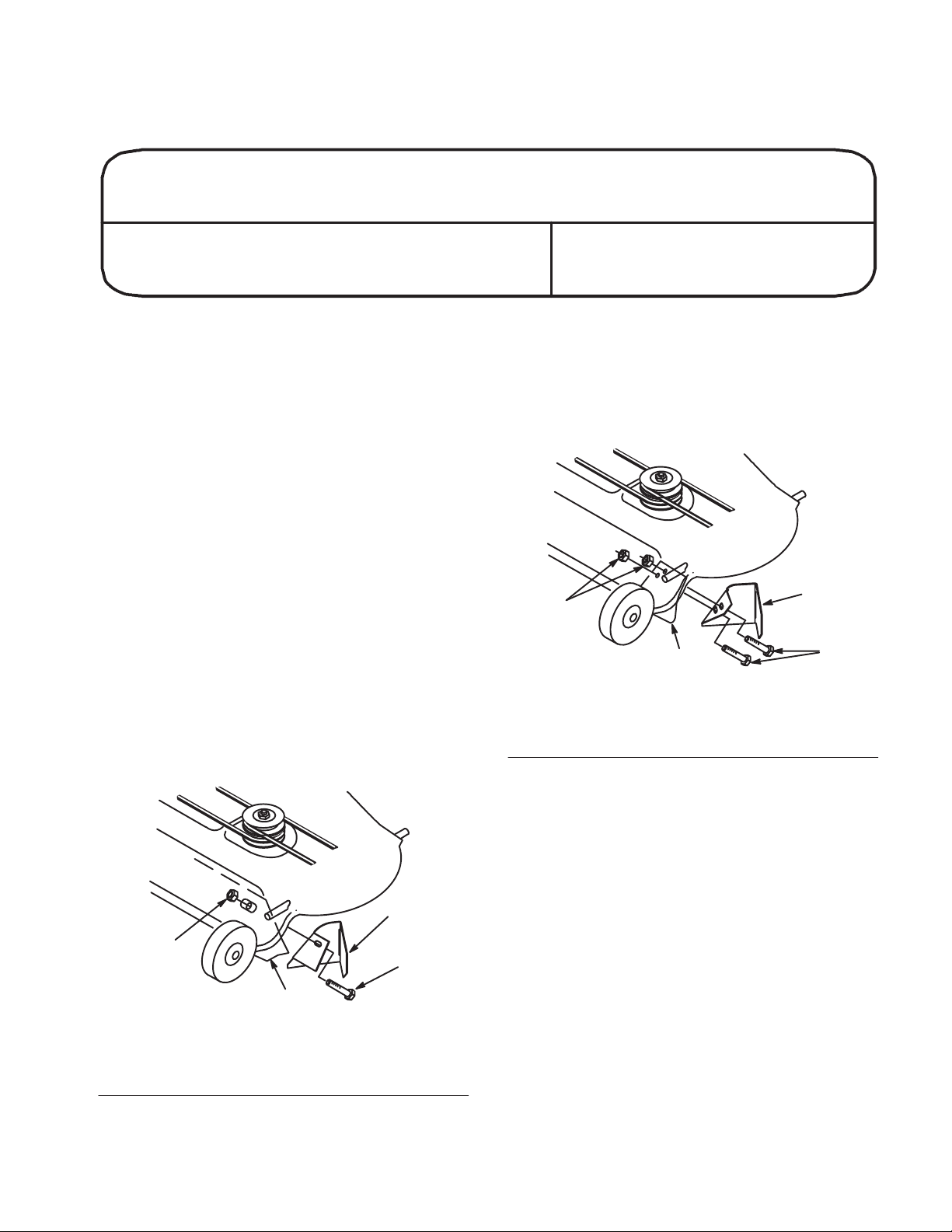
Install Mower Baffle
1. Remove the bolt(s) and nut(s) at the end of the
grass plate. Inside the mower near the back edge
of the discharge opening. Discard the hardware.
2. Select appropriate grass baffle (42” single hole
or 48” two holes) Install grass baffle tight
against grass plate with top edge up against
inside of mower.
3. Secure with new (5/16” x 1”) bolt(s) and (5/16”)
nut(s) (Fig. 1-42” or 2-48”).
4. Rotate blade and check for clearance with baffle.
If necessary adjust baffle so blade does not hit.
4
1. Grass plate
2. 48” Baffle
1
Figure 2
3. Bolt
4. Nut
2
3
1493
4
1. Grass plate
2. 42” Baffle
Printed in USA
1
Figure 1
2
3
1492
3. Bolt
4. Nut
Page 2
Installation Instructions
Mount Blower Pivot Support
5. Select proper hole (42” outside, 48” inside) and
slide pivot support over threaded stud welded to
front of mower near discharge opening (Fig. 3).
6. Align pivot support parallel with front curved
edge and tight against top of mower (Fig. 3).
Clamp in this position.
7. Drill 11/32” diameter hole in top of mower using
the pivot support as a guide. Secure pivot
support to the mower with a (5/16” x 3/4”) bolt,
through from the underside of the mower, and a
flange nut (Fig. 3). Thread jam nut (removed
from discharge chute) snug onto stud. Do not
overtighten jam nut.
7
1
6
2
5
3
4
1494
Assemble Blower
8. Assemble blower mounting plate to blower with
three (5/16” x 3/4”) carriage bolts and flange
nuts (Fig. 4).
9. In the front inside hole of the blower insert a
(5/16” x 1”) bolt. Inside the blower housing slide
the L-bracket over the bolt. Hold the L-bracket
tight against the blower housing wall and secure
with washer and flange nut (Fig. 4).
6
5
1
1. Blower mounting plate
2. Blower assembly
3. Carriage bolt
4. Flange nut
Figure 4
5. L-bracket
6. Bolt
7. Washer
4
2
3
7
4
1495
1. Pivot support
2. Mounting hole 42”
3. Mounting hole 48”
4. Nut
Figure 3
5. Drill 11/32 diameter hole
6. Bolt
7. Flange nut
2
Page 3

Installation Instructions
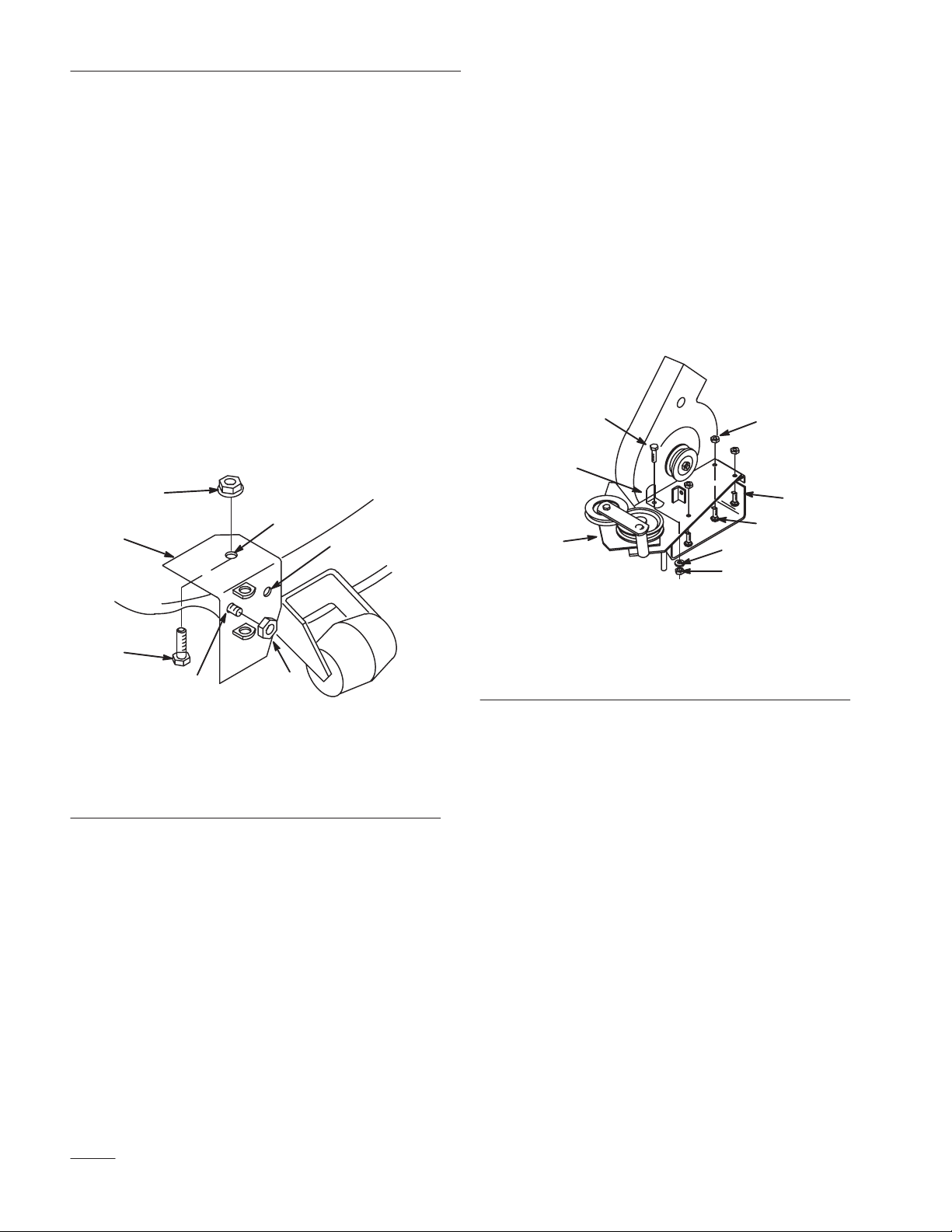
10. Install one end of tension spring and nut onto
(#10 x 3/4”) screw. Thread nut on within 1/8”
from end of screw so spring rotates freely
(Fig. 5).
11. Slide washer onto screw and insert through
blower housing. Secure with second washer and
nut (Fig. 5).
12. Select appropriate latch (42” short, 48” long)
Hook spring into latch and mount to blower
housing with (1\4” x 3\4”) bolt, washer and lock
nut (Fig. 5). Check that latch pivots freely.
5
8
7
3
4
4
3
9
2
1
6
1496
Tractor Set-Up
1. Mount two spacers against inside of tractor
frame with (3\8” x 1-3\4”) bolt and nut (Fig. 6).
2
1
3
Figure 6
1. Bolt
2. Spacer
2
1
1371b
3. Nut
1. Screw
2. Spring
3. Nut
4. Washer
5. Latch
Figure 5
6. Bolt
7. Washer
8. Lock nut
9. Blower assembly
3
Page 4

Installation Instructions
Assemble Bagger Cover
1. Slide threaded end of indicator rod through two
clips, then rubber seal and slot in cover(Fig. 7).
2. Secure clips to the cover with (1\4” x 5\8”) bolts
and nuts (Fig. 7).
3. Thread jam nut and handle completely onto
thread end of indicator rod. Rotate handle so you
can read decal from operators position then
tighten jam nut to secure (Fig. 7).
5
6
1
2
3
4. Mount the frame hinge to the cover with
(1\4” x 3\4”) bolts (already in hinge)s. Secure
with lock nuts (Fig. 8).
2
3
4
Figure 8
1. Frame hinge
2. Cover
3. Bolt
4. Nut
Assemble Discharge Tube
1
4
1374
1. Indicator r o d
2. Clips
3. Bolt
4
Figure 7
4. Nut
5. Handle
6. Jam nut
1370
1. Attach ribber latch to bottom hole in tube. Insert
barbed fastener through rubber latch, tube and
press into flange spacer on inside of tube
(Fig. 9).
1
4
1. Tube
2. Rubber latch
Figure 9
3. Barb fastener
4. Flange spacer
3
2
1498
4
 Loading...