

Page 1

FORM NO. 3319-563 Rev. A
Wheel
Horse
Vac–Bagger
for
42” and 48” L> Mowers
Model No. 79203– 7900651 & Up
Operator’s Manual
IMPORTANT: Read this manual carefully. It contains information about your
safety and the safety of others. Also become familiar with the controls and
their proper use before you operate the product.
Page 2
Introduction
We want you to be completely satisfied with your
new product, so feel free to contact your local
Authorized Service Dealer for help with service,
genuine replacement parts, or other information you
may require.
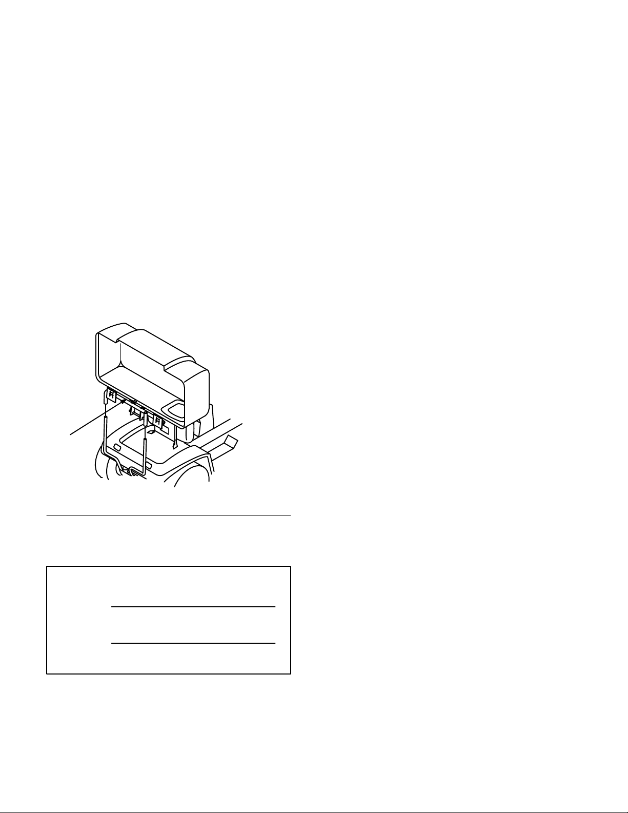
Whenever you contact your Authorized Service
Dealer or the factory, always know the model and
serial numbers of your product. These numbers will
help the Service Dealer or Service Representative
provide exact information about your specific
product. You will find the model and serial number
plate located in a unique place on the product as
shown below
.
The warning system in this manual identifies
potential hazards and has special safety messages that
help you and others avoid personal injury, even death.
DANGER, WARNING and CAUTION are signal
words used to identify the level of hazard. However,
regardless of the hazard, be extremely careful.
DANGER signals an extreme hazard that will cause
serious injury or death if the recommended
precautions are not followed.
WARNING signals a hazard that may cause serious
injury or death if the recommended precautions are
not followed.
CAUTION signals a hazard that may cause minor or
moderate injury if the recommended precautions are
not followed.
Two other words are also used to highlight
information. “Important” calls attention to special
mechanical information and “Note” emphasizes
general information worthy of special attention.
1
1. Model
For your convenience, write the product model and
serial number in the space below.
Model No:
Serial No.
and Serial Number Plate
The left and right side of the machine is determined
by sitting on the seat in the normal operator’s
position.
Printed in USA
The TORO Co. – 1999
Page 3

Contents
Page
Safety and Instruction Decals 2.
Assembly 3
Operation 21
. . . . . . . . . . . . . . . . . . . . . . . . . . . . . .
Loose Parts 3
Preliminary Preparation 5
Preparing the Tractor 6
Preparing the Mower 6
Installing the Vac-Bagger 11
Removing the V
Using the Full Bag Tester 21
Emptying the Grass Bags 21
Adjusting Height-of-Cut 22
Clearing Obstructions
From Bagger 22
Operating and Bagging Tips 22
. . . . . . . . . . . . . . . . . . . . . . . . .
ac Bagger16. . . . . . . . . . . . .
. . . . . . . . . . . . . . . . . . . . . . . . . . . . . .
. . . . . . . . . . . . . . . . . . . . . .
. . . . . . . . . . . . .
. . . . . . . . . . . . . . .
. . . . . . . . . . . . . . . . .
. . . . . . . . . . . . . . . . .
. . . . . . . . . . . . . .
. . . . . . . . . . . . . .
. . . . . . . . . . . . . .
. . . . . . . . . . . . . .
. . . . . . . . . . .
Page
Maintenance 24
Service Interval Chart 24
Inspecting the Vac Bagger Attachment 25
Inspecting the Mower Blades25. . . . . . . . . . .
Caring for the Grass Bags 25
Cleaning the Vac Bagger Attachment 25
Storage 26
. . . . . . . . . . . . . . . . . . . . . . . . . . . .
. . . . . . . . . . . . . . . .
. . .
. . . . . . . . . . . . .
. . . .
. . . . . . . . . . . . . . . . . . . . . . . . . . . .
1
Page 4
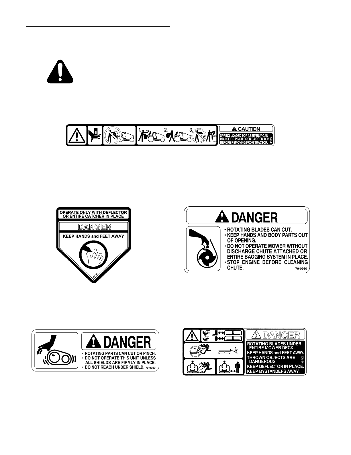
Safety
Safety
MOLDED INT
and Instruction Decals
Safety decals and instructions are easily visible to the operator and are located near
any area of potential danger. Replace any decal that is damaged or lost.
ON INSIDE BAGGER HINGE FRAME
(Part No. 92–71
O THE BEL
T COVER
13)
MOLDED INT
O THE BLOWER HOUSING
AND BEL
T COVER
MOLDED INT
2
O THE BEL
T COVER
ON THE INNER COVER
(Part No. 92–7108)
Page 5

Assembly
Loose
Parts
Note: Use the chart below to identify parts used for assembly.
DESCRIPTION QTY. USE
Bolt 3/8–16 x 1-3/4”
Lock nut 3/8”
Spacer
Grass baf
Carriage bolt 3/8–16 x1” (25 mm)
Lock nut 3/8”
Grass baf
Carriage bolt 3/8–16 x1” (25 mm)
Lock nut 3/8”
Double groove pulley
Pivot support
Bolt 5/16–18 x 3/4” (19 mm)
Flange nut 5/16”
fle (1 hole–42” deck only)
fle (2 holes–48” deck only)
2
2
2
1
1
1
1
2
2
1
1
1
1
Install bagger mount to tractor
Install grass baf
Install grass baf
Install blower drive
Install blower pivot support to mower
fle (42” deck only)
fle (48” deck only)
3
Page 6

Assembly
DESCRIPTION USEQTY.
Blower mounting plate
Blower assembly
Carriage bolt 5/16–18 x 3/4” (19 mm)
Flange nut 5/16”
L–support bracket
Carriage bolt 5/16–18 x 7/8” (22 mm)
W
asher 5/16”
Flange nut 5/16”
Spring
Screw #10–32 x 3/4” (19 mm)
W
asher 7/32”
Nut #10
Latch (long–48” deck only)
Latch (short–42” deck only)
Bolt 1/4–20 x 3/4” (19 mm)
W
asher 1/4”
Lock nut 1/4”
1
1
3
3
1
1
1
1
1
1
2
2
1
1
1
1
1
Assemble the blower
Bagger Cover
Indicator rod
Handle
Jam nut 1/4”
Clips
Pan head screw 1/4–20 x 5/8” 916 mm)
Lock nut 1/4”
Frame hinge assembly
Discharge tube
Knob
W
asher 7/32”
Screw #10–24 x 5/8” (16 mm)
Belt cover (42” deck)
Belt cover (48” deck)
Belt cover bracket (42” deck)
Belt cover bracket (48” deck)
Flange head screw
, 1/4–20 x 1/2” (13 mm)
1
1
1
1
2
2
2
1
1
1
1
1
1
1
1
1
5
Assemble the bagger
Assemble knob to discharge chute
Install belt cover
Bolt 1/4–20 x 5/8” (16 mm)
Lock nut 1/4”
4
2
2
Page 7

DESCRIPTION USEQTY.
Assembly
Spring
Chain
Carriage bolt 5/16–18 x 1-1/4” (32 mm)
W
asher 5/16”
Locknut 5/16”
Bagger mount
Hairpin cotter
Bag
Operator’
Preliminary
s Manual
Preparation
Park the tractor and mower on a level surface,
disengage the blade control (PTO), set the parking
brake, and turn the ignition key to “OFF” to stop the
engine. Remove the ignition key.
Lower the mower to its lowest position and remove
the mower from the tractor. Refer to Mower
Operator’s Manual for removal instructions.
1
1
1
3
1
1
1
2
1
Install counterbalance spring
Install bags
Read before operating
Thoroughly clean the mower deck. All debris must be
removed to ensure that parts will fit the mower
properly.
5
Page 8
Assembly
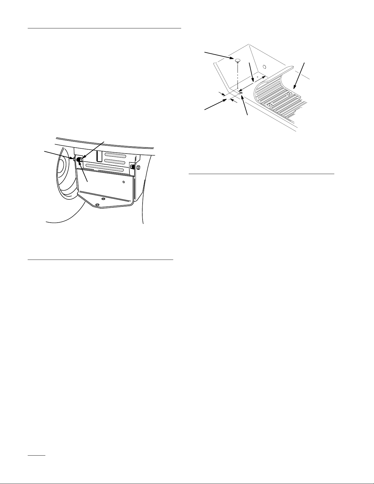
Preparing
the T
ractor
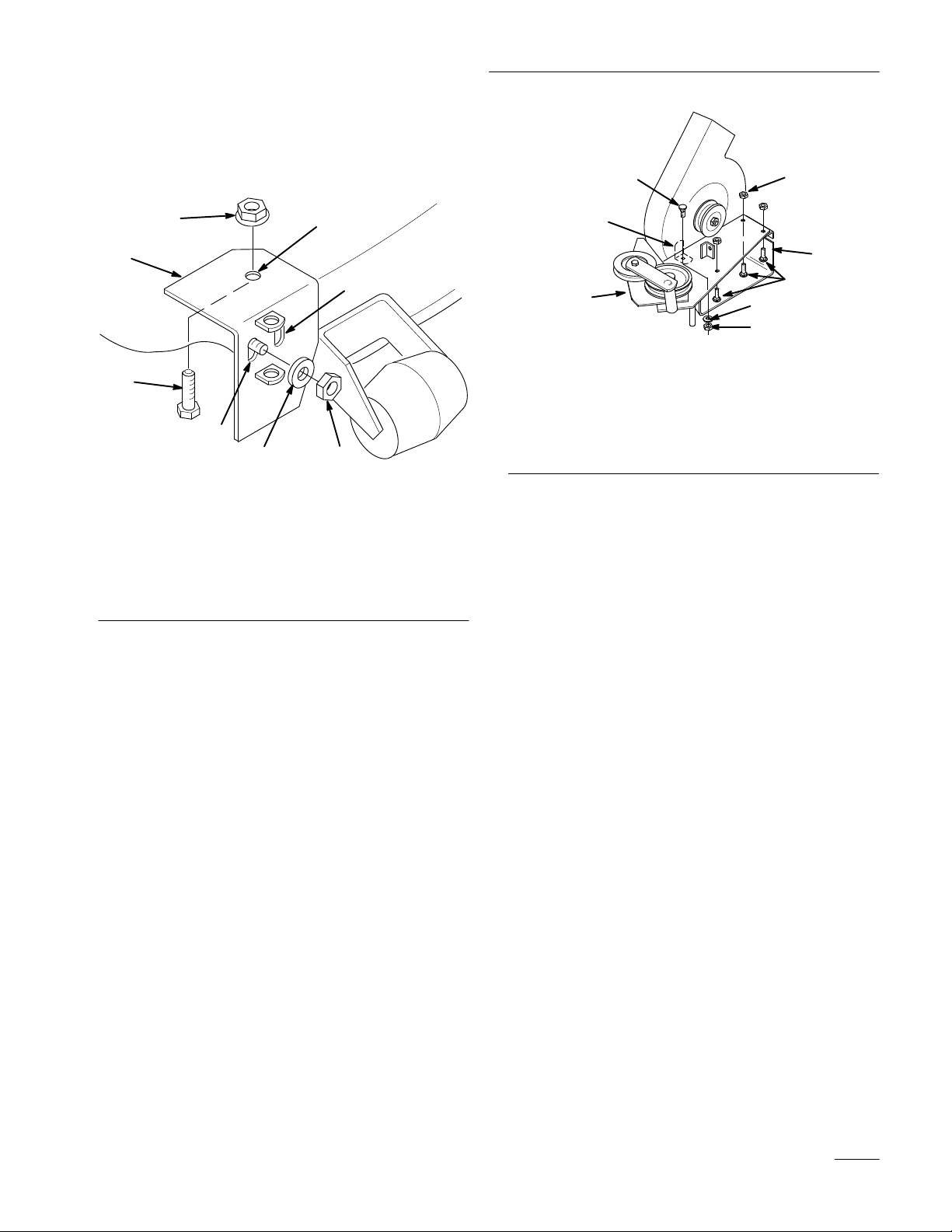
Install Spacers for Bagger Mount
1. Install spacers on the inside of the tractor frame,
using (2) 3/8 x 1-3/4” (44 mm) bolts and (2) 3/8”
lock nuts (Fig. 1).
2. Allow the spacers to remain installed, even when
bagger attachment is not being used.
2268
1
4
1 Plastic
2
Foot pad
3
6-1/2” (16.5 cm)
rivet
3
5
Figure 2
4
1-5/16” (3.3 cm)
5
Drill 5/16” hole – square
of
f with file
2
m–3256
4. Leave pad loose for later installation of bolt for
counterbalance chain.
Preparing
the Mower
Figure 1
1 Spacer
2 Lock
nut 3/8”
3
Bolt 3/8 x 1-3/4”
Add Hole for Counterbalance Chain
1. Push up on plastic rivets at rear of right foot pad
and remove rivets. Lay the pad toware the front
to access the foot rest for drilling a hole (Fig. 2).
2. Measure and mark location, center punch and
drill a 5/16” hole through right foot rest (Fig. 2).
3. Using a file, square off the hole to accept the
head of a 5/16” carriage bolt.(Fig. 2).
Remove the Discharge Chute
1. Remove the discharge chute from the mower
(Fig. 3).
2. Remove belt cover from right side (Fig. 3).
Note: Save all parts and hardware for use
when using mower to side discharge.
6
Page 9
Assembly
2
6
4
8
7
9
3
5
m–3297
Figure 3
1 Discharge
2
Belt cover
3
Blade drive belt
4
Nut and lock washer
5
Single pulley
chute
6
Jam nut, 3/8”
7
Rubber bushing
8
Plastic washers
9T
orsion spring
Install Mower Baffle
IMPORTANT: Only required for s/n below
7904310 for mower deck model 78260 and s/n
below 7902555 for mower deck model 78268.
1. Remove the bolt(s) and nut(s) at the end of the
grass plate, inside the mower, near the back edge
of the discharge opening. Discard the hardware.
2
5
1
1
3
1492
Figure 4
1 Grass
2
42” Baf
plate
fle
Carriage bolt, 3/8 x 1”
3
(25 mm)
4
Nut, 3/8”
4. On 48” decks, secure with two 5/16” x 1” (25
mm) carriage bolts and 5/16” lock nuts (Fig. 5).
2
2. Select the appropriate grass baffle (42” deck,
single hole or 48” deck, two holes) Install the
grass baffle tight against the grass plate with top
edge up against inside of mower.
3. On 42” decks, secure with a 3/8 x 1” carriage
bolt and 3/8” lock nut (Fig. 4).
4
1
1493
3
Figure 5
1 Grass
2
48” Baf
plate
fle
Carriage bolt 5/16 x 1”
3
(25 mm)
4
Nut 5/16”
5. Rotate blade and check for clearance with baffle.
If necessary adjust the baffle so blade does not
hit.
7
Page 10

Assembly
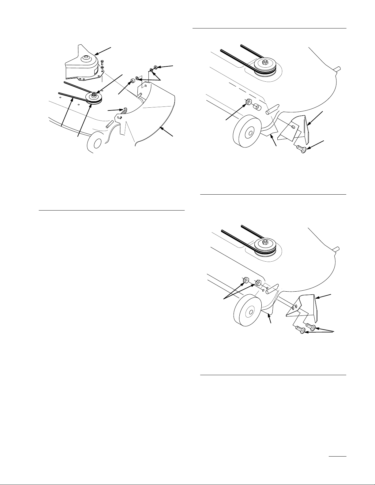
Install Blower Drive Pulley
1. Remove the belt from the right hand spindle
pulley.
2. Remove the nut and lock washer retaining the
pulley (Fig. 6). Remove the single groove pulley.
Note: Block the blade with a piece of wood
to stop it from turning while you
remove the pulley nut. If blade slips
hold hex portion of spindle with a
wrench.
Note: When nut is removed the shaft is free
to drop out of the spindle. Be sure to
support the spindle and blade from the
bottom side.
Note: Use belt part number 79–7480 for 42”
mowers and the belt part number
79–7490 for 48” mowers.
6. Reinstall the existing mower belt onto the top
pulley (Fig. 7).
Note: Check that mower belt is properly
located on idler and pulleys.
1 New double pulley
(note “TOP”)
2 Lock washer and 5/8” nut
Figure 7
3 Mower
4
Blower drive belt
belt
m–3301
m–3301
Figure 6
1 Blade
2
drive belt
Nut and lock washer
3
Single pulley
3. Slide the new double pulley onto the spindle
shaft with the word “TOP”, stamped into largest
pulley, facing up. Secure with previously
removed 5/8” lock washer and nut (Fig. 7).
4. Tighten the nut to 50–75 ft. lb. (68–101 Nm).
5. Install the blower drive belt around the bottom
pulley as shown (Fig. 7).
Install Blower Pivot Support
1. Select the proper hole in the pivot support (42”
deck–outside, 48” deck–inside) and slide it over
the threaded stud welded to front of mower near
discharge opening (Fig. 8).
2. Align pivot support parallel with front curved
edge and tight against top of mower (Fig. 8).
Clamp in this position.
3. Drill a 11/32” diameter hole in the top of the
mower deck using the pivot support as a guide.
Secure the pivot support to the mower with a
5/16 x 3/4” (19 mm) bolt, through from the
underside of the mower, and a flange nut (Fig.
8
Page 11
8). Place the 3/8” jam nut (removed from
discharge chute) snug onto stud. Do not
overtighten jam nut.
Assembly
6
4
7
5
1
3
6
2
8
4
1494
Figure 8
1 Pivot
2
3
4
support
Mounting hole 42”
Mounting hole 48”
Jam nut 3/8”
(removed from discharge
chute)
Drill 1
5
6
7
8
1/32 diameter hole
Bolt 5/16 x 3/4” (19 mm)
Flange nut 5/16”
Plastic washer (removed
from discharge chute)
Assemble Blower
1. Assemble blower mounting plate to blower with
(3) 5/16 x 3/4” carriage bolts and (3) 5/16”
flange nuts (Fig. 9).
2. In the front inside hole of the blower insert a
5/16 x 1” carriage bolt, item 6 (Fig. 9).
Note: This carriage bolt must be installed
down through the plate and blower for
proper belt clearance.
5
2
3
1
7
4
1495
Figure 9
1 Blower
2
3
4
mounting plate
Blower assembly
Carriage bolt 5/16 x 3/4”
(19 mm)
Flange nut 5/16”
5 L-bracket
6
Carraige bolt 5/16 x 7/8”
(22 mm)(down from top)
7W
asher 5/16”
4. Install the long hook end of tension spring and
#10 nut onto a #10 x 3/4” screw. Thread the nut
on within 1/8” from the head end of screw so
that the spring has space to rotate freely
(Fig. 10).
5. Slide a #10 washer onto the screw and insert
through the blower housing. Install a second
#10 washer and #10 nut (Fig. 10). While
holding the first nut, tighten the second so that
the assembly is tight against the plastic housing.
6. Select the appropriate latch (42” deck–short, 48”
deck–long) Hook the spring into the hole in the
latch and mount the latch to the blower housing
with a 1/4 x 3/4” (19 mm) bolt, 1/4” washer and
1/4” lock nut (Fig. 10). Leave the nut loose
enough so that the latch pivots freely.
3. Inside the blower housing, slide the L-bracket
over the bolt. Hold the L-bracket tight against
the blower housing wall and secure with 5/16”
washer and 5/16” flange nut (Fig. 9).
9
Page 12
Assembly
5
8
2
7
3
4
4
3
Figure 10
1 Screw
2 Spring
3
4W
5 Latch
#10 x 3/4” (19 mm)
Nut #10
asher #10
Bolt 1/4 x 3/4” (19 mm)
6
7W
asher 1/4”
8
Lock nut 1/4”
9
Blower assembly
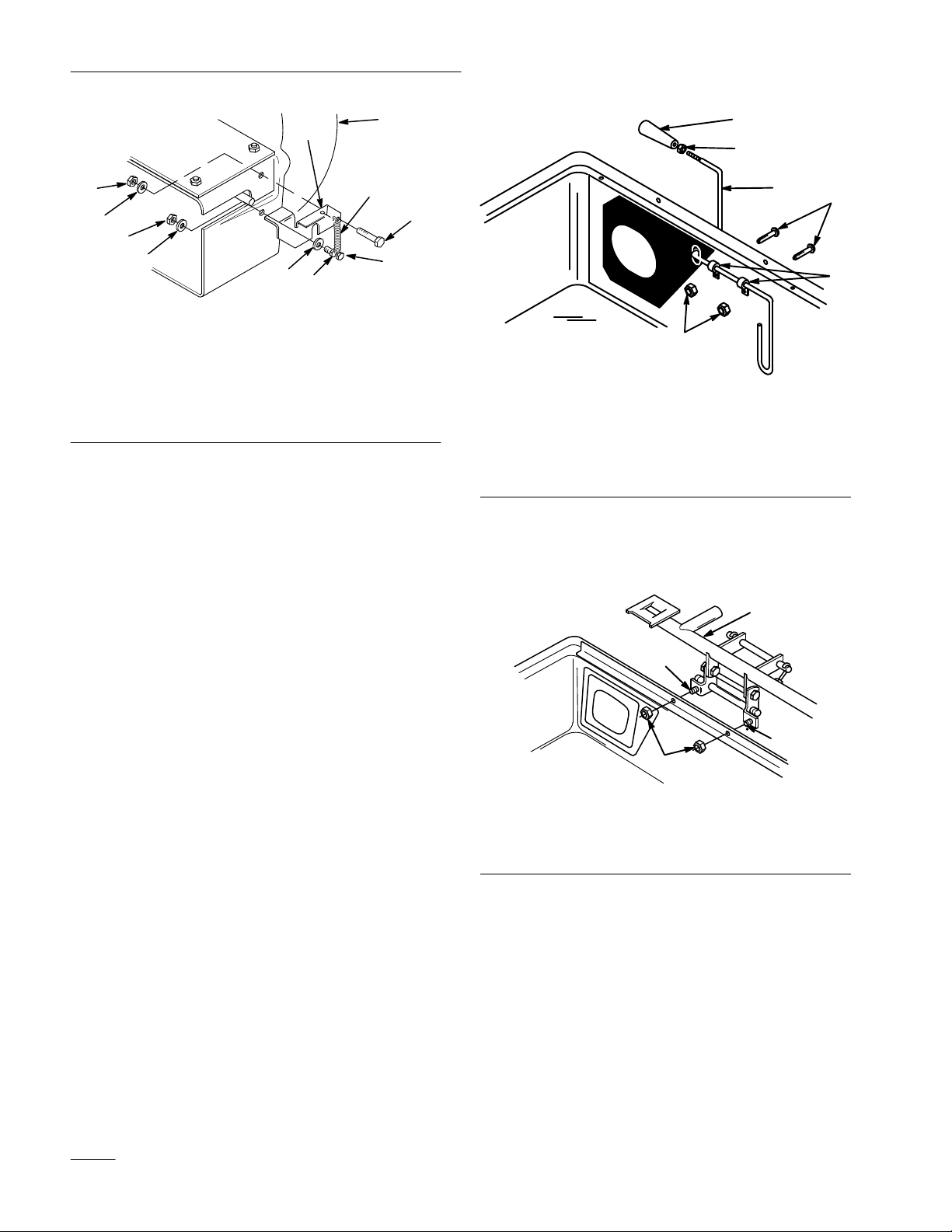
Assemble Bagger Cover
1. Slide the threaded end of the indicator rod
through (2) clips, then rubber seal and slot in
cover (Fig. 11).
9
6
5
1
3
6
1
1496
2
4
1370
1 Indicator
2 Clips
3
Pan head screw 1/4 x 5/8”
(16 mm)
rod
Figure 1
1
4
Lock nut 1/4”
5
Jam nut 1/4”
6 Handle
4. Mount the frame hinge to the cover with the (2)
1/4” bolts attached to it. Secure with (2) 1/4”
lock nuts (Fig. 12).
2. Secure the clips to the cover with (2) 1/4 x 5/8”
(16 mm) pan head screws and (2) 1/4” lock nuts
(Fig. 11).
3. Thread the jam nut and handle completely onto
the threaded end of indicator rod. Rotate the
handle so that the decal can be read from the
operators position, then tighten the jam nut
(Fig. 11).
1 Frame
2
hinge
Bolt 1/4” (attached)
Figure 12
3
1374
Lock nut 1/4”
10
Page 13
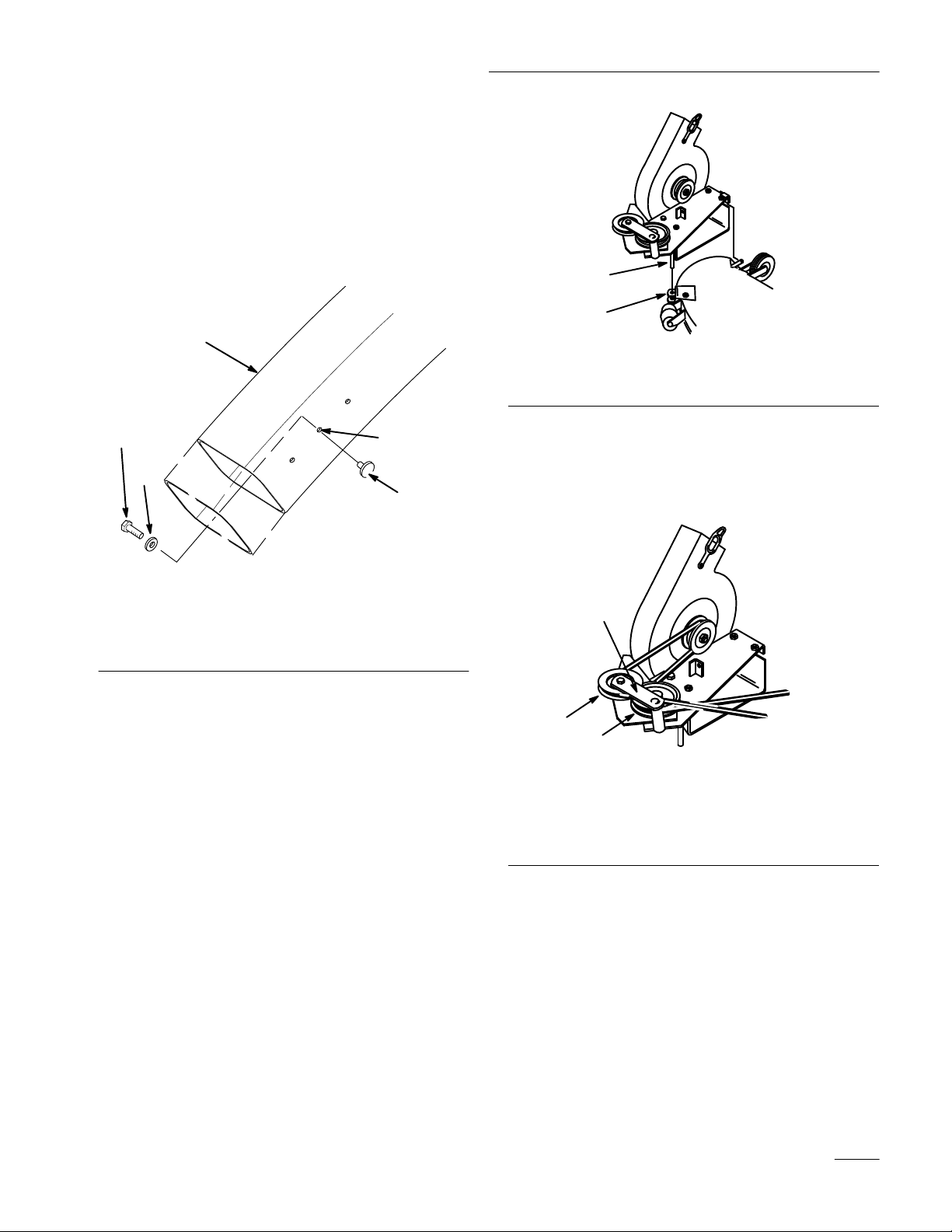
Assemble Discharge Tube
1. Cut 2-3/4” (7 cm) off the bottom of the discharge
tube (Fig. 13).
1. Attach the knob to the center hole in the
discharge tube and secure with a 7/32” washer
and #10–24 x 5/8” (16 mm) screw (Fig. 13).
Assembly
1
5
2
4
3
m–1981
Figure 13
1 Discharge
2T
ube center hole
3 Knob
tube
Installing
the V
4W
asher 1/4”
5
Screw #10–24 x 5/8”
(16 mm)
ac-Bagger
Mount the Blower
1. Insert pivot pin on blower into pivot support
bracket on mower (Fig. 14).
1838
Figure 14
1 Pivot
pin
2
Pivot support bracket
2. With the blower swung out in the open position,
install the blower drive belt between the idler
pulley bracket and pulleys. Then loop the belt
around the blower pulley (Fig. 15).
1
3
2
1 Idler
pulley bracket and
pulley
2T
op side of belt against
bottom pulley
Figure 15
3
V–side of belt into top
pulley
1839
3. With the belt installed, swing the blower toward
the mower until the blower latch locks over the
pin at the back of the mower (Fig. 16).
11
Page 14

Assembly
1840
Figure 16
1 Blower
latch
2 Pin
Install Belt Cover
1. Two belt covers and one bracket for a 42” deck
are supplied.
2. On 42” mowers, mount the belt cover bracket
using (2) 1/4 x 1/2” (13 mm) thread forming
flange screws in holes used by original cover
(Fig. 17).
Note: Do not tighten screws as adjustment
must be made later.
1 Belt
cover 42”
Figure 18
2
Flange screws 1/4 x 1/2”
thread forming
m–3
4. On 48” mowers mount belt cover loosely on top
of mower with (2) 1/4 x 3/8” flange screws
(Fig. 19).
Note: Do not tighten screws as adjustment
must be made later.
2
1
m–3302
Figure 17
1 Belt
cover bracket 42”
2
Flange head 1/4 x1/2” (13
mm) thread forming screw
Note: Center slots of cover bracket before
tightening flange screws.
3. On 42” mowers, mount the belt cover loosely to
the outside of the belt cover bracket and top of
the mower using (3) 1/4 x 1/2” flange screws
(Fig. 18).
1 Belt
cover 48”
2
Flange screws 1/4 x 3/8”
thread forming
Figure 19
3
m–3304
Flange screws 1/4 x 1/2”
thread forming
12
Page 15

Assembly
Install Blower Belt Cover
1. Mount blower belt cover using (2) 1/4 x 5/8”
bolts and (2) 1/4” lock nuts (Fig. 20). Tighten
lock nuts slightly so light drag is felt on belt
cover when tilted upward. Cover must close
freely when assembled.
2. Adjust mower belt cover by sliding so blower
belt cover so that it just touches the blower, but
still opens freely. Tighten mower belt cover
mounting screws.
2 & 3
1
3
remaining links hang toward the rear. Secure
with a third washer and a 5/16” locknut
(Fig. 21).
3. Hook the spring around the wheel shaft at the
rear of mower and into one of the chain links
(Fig. 21). Refer to Operation Section ,
“Adjusting Height–of–Cut” for recommended
chain link setting.
1
2
4
4
3
5
6
2
1997
Figure 20
1 Blower
2
belt cover
Bolt 1/4 x 5/8” (16 mm)
3
Lock nut 1/4”
4
Mower belt cover
Reinstall Mower to Tractor
1. Reinstall the mower to the tractor. Refer to the
“Installing the Mower” in the Mower Operator
Manual.
Attach Counterbalance Chain
1. Place a 5/16 x 1 1/4” (32 mm) carriage bolt
through the squared hole (added in “Tractor
Preparation”) in the right hand footrest (Fig. 21).
2. Place two 5/16” (19 mm) washers and a link on
one end of the chain onto the carriage bolt.
Position the end link on the bolt so that the
m–3254
Figure 21
1 Carriage
1-1/4” (32 mm)
2
Mounting Link
3W
bolt 5/16–18 x
asher 5/16”
4 Chain
5
Locknut 5/16”
6 Spring
4. Reinstall the foot rest pad using the two plastic
rivets removed earlier.
Install Bagger Assembly
1. Slide the bottom of the quick-attach bracket
down into the hole in the hitch and hook the
notches onto the spacers located inside the
tractor frame (Fig. 22).
2. Slide the hair pin cotter through the hole at the
bottom of the quick-attach bracket (Fig. 22).
13
Page 16

Assembly
3
3
1
2
4
Figure 22
1 Quick-attach
2
Hole in hitch
bracket
3 Spacers
4
Hair pin cotter
3. Tip the tractor seat forward.
4. With lid in the open position carefully lift the
bagger top and slide it onto the quick-attach
bracket (Fig. 23).
2267
POTENTIAL
HAZARD
• The hinge frame on the bagger top is
spring-loaded.
WHAT CAN HAPPEN
• If you remove the bagger top when it is
closed (in the down position), the top may
suddenly fly open and you or someone else
may be bruised, pinched, or injured in
another way.
HOW TO AV
OID THE HAZARD
• Always open (raise) the bagger top before
you remove or install it on the quick-attach
bracket.
5. Install the bags by sliding the bag frame hooks
onto the retaining brackets (Fig. 24).
1
2
1 Bagger
top
Figure 23
2
Quick-attach bracket
1 Bag
frame hook
Figure 24
2
1
2
1373
Retaining bracket
14
Page 17

Assembly
6. Lower the bagger top onto the bags. Then push
down on both bag retainer handles until they
lock on the bag frame (Fig. 25).
1
2
1376
Figure 25
1 Bagger
top
2
Bag retainer handles
Install Discharge Tube
1. Move the tractor seat to its normal position.
4. Check the side to side level of the mower at the
desired cutting height. Due to varying
conditions, it may be necessary to relevel the
mower after installing the vac bagger. If so,
refer to “Leveling the Mower Side to Side” in
Mower Operator Manual.
2. Insert the upper end of the discharge tube into
the bagger top. Slide the lower end of the
discharge tube over the blower opening
(Fig. 26).
3. Hook the rubber latch over knob (Fig. 26).
1
2
3
Figure 26
1 Discharge
2
Rubber latch
tube
3 Knob
1847
15
Page 18

Assembly
Removing
POTENTIAL
the V
HAZARD
ac Bagger
• Sometimes people are tempted to operate
the tractor and mower without both grass
bags installed on the Twin Bagger or with
the discharge tube r
emoved. This exposes
you and others to thrown debris and blade
contact.
WHAT CAN HAPPEN
• You and others may die or be injured
severely if you are hit by thrown debris or
cut by the blade.
HOW TO AV
OID THE HAZARD
• Always operate the mower with either the
complete T
mounted in place or use the mower to side
discharge, making sure that the
spring-loaded grass deflector is in the down
position.
win Bagger grass catcher
1
2
1847
Figure 27
1 Rubber
latch
2 Knob
Remove the Bagger Top
1. Tip the tractor seat forward.
2. Raise the bagger top and remove the grass bags
from the bag frame (Fig. 28).
1
Remove the Discharge Tube
1. Unhook the rubber latch from the knob (Fig. 27).
2. Slide the lower end of the discharge tube off the
blower discharge opening (Fig. 27). Pull the
upper end of discharge tube out of bagger top.
1 Bagger
top
2
Figure 28
2
Bag retainer handles
1376
16
Page 19

Assembly
3
POTENTIAL
HAZARD
• The hinge frame on the bagger top is
spring-loaded.
WHAT CAN HAPPEN
• If you remove the bagger top when it is
closed (in the down position), the top may
suddenly fly open and you or someone else
may be bruised, pinched, or injured in
another way.
HOW TO AV
OID THE HAZARD
• Always open (raise) the bagger top before
you remove or install it on the quick-attach
bracket.
3. With the lid in the open position carefully lift the
bagger top and slide off the quick-attach bracket
(Fig. 29).
1
1
3
2
4
2267
Figure 30
1 Quick-attach
2
Hole in hitch
bracket
3 Spacers
4
Hair pin cotter
5. Move the tractor seat to its normal position.
Remove Blower Belt Cover
1. Remove the blower belt cover by removing (2)
1/4’ lock nuts and 1/4 x 5/8” bolts (Fig. 31).
Note: Save all parts and hardware for use
when installing blower.
2
Figure 29
1 Bagger
top
2
Quick-attach bracket
4. Remove the hairpin cotter and slide the bottom
of the quick-attach bracket up out of the hole in
the hitch and unhook from the spacers located
inside the tractor frame (Fig. 30).
1
1 Mower
2
belt cover
Bolt 1/4 x 5/8” (16 mm)
2 & 3
3
2
1997
Figure 31
3
Lock nut 1/4”
17
Page 20

Assembly
Remove the Blower from the Mower
1. Open latch and swing the blower out away from
the mower, remove the blower belt from idler
and blower pulleys (Fig. 32).
1
3
2
1 Idler
2T
pulley bracket and
pulley
op side of belt against
bottom pulley
Figure 32
3
V–side of belt into top
pulley
1839
Remove the Mower Belt Cover
1. Remove the mower belt cover from the right side
pulley (Fig. 34). Save mounting hardware.
1
2
m–3303
Figure 34
1 Belt
cover–42”
2
Belt cover–48”
2. On 42” mower, remove the belt cover bracket
(Fig. 35).
m–3304
2. Remove the blower by lifting the pivot pin out
of the pivot support (Fig. 33).
1
2
1838
Figure 33
1 Pivot
pin
2
Pivot support
Remove Counterbalance Spring and
Chain
1. Unhook the chain from the footrest and the
spring from the gage wheel shaft and remove for
reuse. Reinstall the nut and washer to the bolt in
the footrest.
1
2
Figure 35
1 Belt
cover bracket 42”
2
Flange head screws
Remove the Blower Drive Belt
1. Pull on mower idler assembly to release belt
tension and remove blade drive belt from right
side pulley (Fig. 36).
2. Remove blower drive belt.
Note: The double groove pulley can be left
on for later use.
m–3302
18
Page 21

3. Reinstall the existing blade drive belt by rotating
it onto the top pulley (Fig. 36).
Assembly
4
Note: Check that mower belt is properly
located on idler and pulleys.
m–3301
Figure 36
1 Double pulley
2 Lock washer and nut
3 Blade
drive belt
Remove the Blower Pivot Support
1. Remove the pivot support from the mower
(Fig. 37).
1
3
1 Pivot
2 Nut
3 Bolt
support
5
Figure 37
4
5
2
Flange nut
Plastic washer
1494
Note: Save all parts and hardware for use
when installing blower.
19
Page 22

Assembly
Install Belt Cover and Discharge Chute
1. Install the discharge chute onto the mower with
saved hardware (Fig. 38).
2. Install the original belt cover onto the mower
with saved hardware (Fig. 38).
2
6
4
8
7
9
3
1 Discharge
2
Belt cover
3
Blade drive belt
4
Nut and lock washer
5
Single pulley
chute
5
m–3297
1
Figure 38
6
Jam nut, 3/8”
7
Rubber bushing
8
Plastic washers
9T
orsion spring
20
Page 23

Operation
To Avoid Personal Injury:
• Become familiar with all operating and
safety instructions in the operator’s manual
for your tractor and mower before using
this attachment.
•
Never r
bagger top, or the blower while the engine
is running.
• Always shut the engine off before clearing
an obstruction from the vac bagging
system.
• Never do maintenance or repairs while the
engine is running.
Using
As grass is cut and blown into the bags, the left bag
fills first, then the right bag. If you overfill the bags,
grass will eventually plug the discharge tube or
elbow.
emove the discharge tube, bags,
the Full Bag T
ester
1
2
1381
Figure 39
1 Full
bag tester handle
Emptying
Grass bags can weigh up to 90 lb (41kg) when full.
Be careful when lifting or handling a grass bag that is
full. To empty the grass bags:
1. Stop the tractor, set the parking brake, and
disengage the power take off (PTO) by pushing
the PTO control to OFF (this stops the mower
blades). Shut the engine off before you get off
the tractor.
the Grass Bags
2
Bag full
1. Stop the tractor and apply the brake.
2. To check if both bags are full, periodically raise
the full bag tester handle (Fig. 39). If you feel
resistance as you raise the handle, the bags must
be emptied because they are full (Fig. 39).
2. Tip the tractor seat forward.
3. Pull up on both bag retainer handles until they
unlock from the bag frame (Fig. 25). Now open
(raise) the bagger top.
4. Compress debris into the bags. With both hands,
lift up on the bag and unhook it from the
retaining bracket (Fig. 24). Empty the bag.
Repeat for the other bag.
5. Install the bags by sliding the bag frame hooks
onto the retaining brackets (Fig. 24).
6. Lower the bagger top onto the bags. Then push
down on both bag retainer handles until they
lock on the bag frame (Fig. 25).
7. Move the tractor seat to its normal position.
21
Page 24

Operation
Adjusting
When mower height-of-cut is changed, the spring
location in the chain links must also be changed.
1. Select spring attachment link according to chart
for the height-of-cut used.
2. Hook spring into recommended link (Fig. 40).
Height-of-Cut
1
2
3
m–3255
Clearing
Obstructions
From Bagger
1. Stop the tractor, shift into neutral, set the parking
brake, push the PTO control to OFF (this stops
the mower blades), turn the ignition key to OFF
to stop the engine, and remove the key from the
switch.
2. Check the grass bags and empty them if they are
full.
3. Remove and separate the discharge tube and
blower from the bagger top and mower. Using a
stick or similar object, carefully remove and
clear the obstruction from the mower, discharge
tube, blower, and the bagger top.
4. After you remove the obstruction, install the
complete bagger system and resume operation.
Operating
and Bagging T
ips
1 Mounting
2
Link 1
1–2 in. (25–51 mm)
2–3 in. (51–76 mm)
3–4 in. (76–101 mm)
Link
Height-of-Cut
Figure 40
3
Spring Hook
Recommended
Link Position
4
3
2–3
Size
Remember that the tractor is longer and wider with
this attachment installed. By turning too sharply in
confined places you may damage the attachment.
Trimming
Always trim with the left side of the mower. Do not
trim with the right side of the mower because you
could damage the bagger’s blower and discharge tube.
Cutting Height
Do not set the mower cutting height too low because
long grass surrounding the mower can prevent air
from getting under the mower and entering the
bagging system. If enough air doesn’t get under the
mower, the bagging system will plug.
Cutting Frequency
Cut the grass often, especially when it grows rapidly.
You will have to cut your grass twice if it gets
excessively long (refer to Bagging Long Grass,
page 23).
22
Page 25

Cutting Technique
For best lawn appearance, be sure to slightly overlap
the mower into the previously cut area. This helps
reduce the load on the engine and reduces the chance
of plugging the blower and discharge tube.
Using Bags
Although not required, bags may be inserted into
each cloth grass bag as a liner to collect clippings and
make disposal more convenient (Fig. 41). If you use a
bag liner, remove the filled grass bag and close the
top of the liner. Then pull the liner out the grass bag
or turn the bag upside down while holding the handle
on the bottom of the grass bag (allows liner to slide
out).
2
Operation
POTENTIAL HAZARD
• As the grass bags fill, extra weight is added
to the back of the tractor.
WHAT CAN HAPPEN
• If you stop and start suddenly on hills, you
may lose steering control or the tractor may
tip.
HOW TO AV
OID THE HAZARD
• Do not start or stop suddenly when going
uphill or downhill. Avoid uphill starts.
• If you do stop the tractor when going
uphill, disengage the PTO (stop the mower
blades) by pushing the PTO control to
OFF. Then back down the hill using slow
r
everse speed.
• Do not change speeds or stop on slopes.
1
1378
Figure 41
1 Cloth
grass bag
2
Bag (liner)
Bagging Speed
Most often you will bag with the tractor throttle in the
FAST position and drive at a normal ground speed.
However, in extremely dry and dusty grass, you may
want to slightly reduce throttle speed and increase
ground speed of the tractor. The bagging system may
plug if you drive too fast and the engine speed gets
too slow. On hills it may be necessary to slow the
tractor’s ground speed. This helps maintain engine
speed and bagging efficiency. Mow down hill
whenever possible.
Bagging Long Grass
Excessively long grass is heavy and may not be
propelled completely into the grass bags. If this
happens, the discharge tube and blower may plug. To
avoid plugging the bagging system, mow the grass at
a high height-of-cut, then lower the mower to your
normal cutting height and repeat the bagging process.
Bagging W
et Grass
Always try to cut grass when it is dry because your
lawn will have a neat appearance. If you must cut wet
grass, use the conventional side discharge feature of
the mower. Several hours later, when the clippings are
dry, install the complete bagger attachment and
vacuum up the grass clippings.
Signs of Plugging
As you are bagging, a small amount of grass
clippings normally blow out the front of the mower.
An excessive amount of clipping blow-out indicates
that the bags are full or the system is plugged.
23
Page 26

Maintenance
Service
Service
Cutter Blade—check
Grease–Mower deck
Belts—check for wear/cracks
Mower Housing—clean
Chipped Surfaces—paint
Interval Chart
Operation
POTENTIAL HAZARD
• If you leave the key in the ignition switch, someone could start the engine.
WHAT CAN HAPPEN
• Accidental starting of the engine could seriously injure you or other bystanders.
HOW TO AV
OID THE HAZARD
• Remove the key from the ignition switch and pull the wire off the spark plug before
you do any maintenance. Also push the wire aside so it does not accidentally contact
the spark plug.
Each
Use5Hours25Hours
X X X
X X
X X X
Storage
Service
X
X
Spring
Service
Notes
24
Page 27

Maintenance
Inspecting
the V
ac Bagger
Attachment
Inspect the blower and bagger attachment after the
first ten hours of operation, and monthly thereafter.
1.
Check the dischar
top. Replace these parts if they are cracked or
broken.
2. Tighten all nuts bolts and screws.
3. Inspect the grass bags for deterioration.
POTENTIAL HAZARD
• The grass bag material may tear, wear, and
eventually deteriorate.
WHAT CAN HAPPEN
• You or bystanders could be severely injured
by flying debris or thrown objects that may
pass through worn or deteriorated grass
bags.
HOW TO AV
• Frequently check the grass bags for holes,
rips, wear, and other deterioration. Do not
wash the grass bags. If the bag has
deterioated, install new grass bags supplied
by the manufacturer of this bagger
attachment.
Inspecting
1. Inspect the mower blades regularly and
whenever a blade strikes a foreign object.
2. If blades are badly worn or damaged, install new
blades. Refer to your tractor or mower operator’s
manual for complete blade maintenance.
ge tube, elbow, and the bagger
OID THE HAZARD
the Mower Blades
Caring
1. Washing the grass bags is not recommended.
2. To prevent rapid deterioration of bag material,
POTENTIAL HAZARD
for the Grass Bags
store the bags so they dry completely after each
use.
• If you store grass clippings in the bagger
attachment cloth grass bags, under the
right conditions, spontaneous combustion
(a fire-generating pr
without an external source of ignition)
could occur.
WHAT CAN HAPPEN
ocess that occurs
• If a fire occurs, property could be damaged
and/or someone could be injured.
HOW TO AV
OID THE HAZARD
• The cloth grass bags are not storage
containers. Never store grass clippings and
debris in the grass bags.
Cleaning
the V
ac Bagger
Attachment
1. After each use, remove and wash the inside and
outside of the bagger top, discharge tube,
discharge elbow, blower and the underside of the
mower, using water sprayed from a garden hose.
Use a mild automotive detergent to remove
stubborn dirt.
2. Make sure you remove matted grass from all
parts.
3. After washing let all parts dry thoroughly. Do
not wash the grass bags.
25
Page 28

Maintenance
Storage
1. Clean the bagger attachment (refer to Cleaning
the Vac Bagger Attachment, page 25).
2. Inspect the bagger attachment for damage (refer
to Inspecting the Vac Bagger Attachment,
page 25).
3. Make sure the grass bags are empty and
thoroughly dry.
4. Store the machine in a clean, dry place, out of
direct sunlight. This protects the plastic parts and
extends the life of the machine. If you must store
the machine outside, cover it with a
weatherproof cover.
26
 Loading...