

Toro 78281 Parts Catalogue
Form No. 3325–631
52 inch Mower
Wheel HorseLawn And Garden Tractor
Attachment
Model No. 78281–210000001 and Up
Parts Catalog
Ordering Replacement Parts
To order replacement parts, please supply: the part
number, the quantity, and the description of each
part desired.
Understanding Reference Numbers
Each identified part in an illustration has a reference
number. The reference number for a part also appears in
the parts list, along with other information about the part.
This catalog uses two special reference number formats,
one to indicate parts in a service assembly and another
to indicate the quantity of a given part in an illustration.
Service Assembly Reference Numbers
Parts in service assemblies have reference numbers in
the form a:b.
the entire service assembly and the b represents a
sequential number unique to each part within the service
assembly.
The a represents the reference number of
The TORO Company — 2001
All Rights Reserved
For example, a wheel assembly might be identified by
reference number 6, the tire by 6:1, the valve by 6:2,
and the wheel by 6:3. When you order the assembly
identified by reference number 6, you receive all parts
identified by reference numbers 6:1, 6:2, and 6:3.
However, you may also order any part individually.
Reference numbers of this type appear in illustrations
and in part lists.
Reference Numbers Indicating Quantity
In an illustration, if a reference number indicates more
than one part, the reference number has the form nX y.
The n represents the quantity of the part, the X is the
multiplication symbol, and the y represents the reference
number.
For example, in an illustration, the reference number
2X 37 means that two of the parts identified by reference
number 37 are indicated.

3325–631
Contents
Description Page Description Page
Gage Wheels And Lift Brackets Assembly 3. . . .
Blades, Spindles, And Deflector Assembly 4. . . .
Deck Assembly No. 99–8019 5. . . . . . . . . . . . . . .
Drive Pulleys And Belt Covers Assembly 6. . . . .
Belt Guide And Plug Bolts Assembly 7. . . . . . . . .
Part Description Abbreviations
Part descriptions in this catalog may include the following abbreviations.
Abbreviation Meaning Abbreviation Meaning
AR as required. . . . . . . . . . . . . . . . .
ASM assembly. . . . . . . . . . . . . . . .
CARR carriage. . . . . . . . . . . . . .
DEG degrees. . . . . . . . . . . . . . . .
FH flat head. . . . . . . . . . . . . . . . .
GA gauge. . . . . . . . . . . . . . . . .
HF hex flange. . . . . . . . . . . . . . . . .
HH hex head. . . . . . . . . . . . . . . . .
HHF hex head flange. . . . . . . . . . . . . . . .
HLH hex lag head. . . . . . . . . . . . . . . .
HJ hex jam. . . . . . . . . . . . . . . . . .
HOC height-of-cut. . . . . . . . . . . . . . . .
HS hex socket. . . . . . . . . . . . . . . . .
HSBH hex socket button head. . . . . . . . . . . . . .
HSFH hex socket flat head. . . . . . . . . . . . . . .
HSH hex socket head. . . . . . . . . . . . . . . .
HWH hex washer head. . . . . . . . . . . . . . .
HWHTF hex washer head. . . . . . . . . . . . .
thread forming
INC incorporated. . . . . . . . . . . . . . . . .
LH left hand. . . . . . . . . . . . . . . . .
NI nylon insert. . . . . . . . . . . . . . . . . .
PPH Phillips pan head. . . . . . . . . . . . . . . .
PTH Phillips truss head. . . . . . . . . . . . . . . .
PTO power take off. . . . . . . . . . . . . . . .
RH right hand. . . . . . . . . . . . . . . . .
SFH slotted fillister head. . . . . . . . . . . . . . . .
SHH slotted hex head. . . . . . . . . . . . . . . .
SQH square head. . . . . . . . . . . . . . . .
SHWH slotted hex washer head. . . . . . . . . . . . . .
SPH slotted pan head. . . . . . . . . . . . . . . .
SRH slotted round head. . . . . . . . . . . . . . . .
STD standard. . . . . . . . . . . . . . . .
TAP self tapping. . . . . . . . . . . . . . . .
TTH Torx truss head. . . . . . . . . . . . . . . .
WH wing head. . . . . . . . . . . . . . . . .
2
34
35
1
2
3
5
4
7
6
8
10
9
11
12
2X 9
4X 13
3325–631
19 (2)
29
28
36
27
31
30
19 (2)
32
33
26
20
2X 9
2X 10
22
25
21
24
2X 9
23
19
2X 9
2X 13
18
2X 9
14
15
17
16
Sheet No.:2
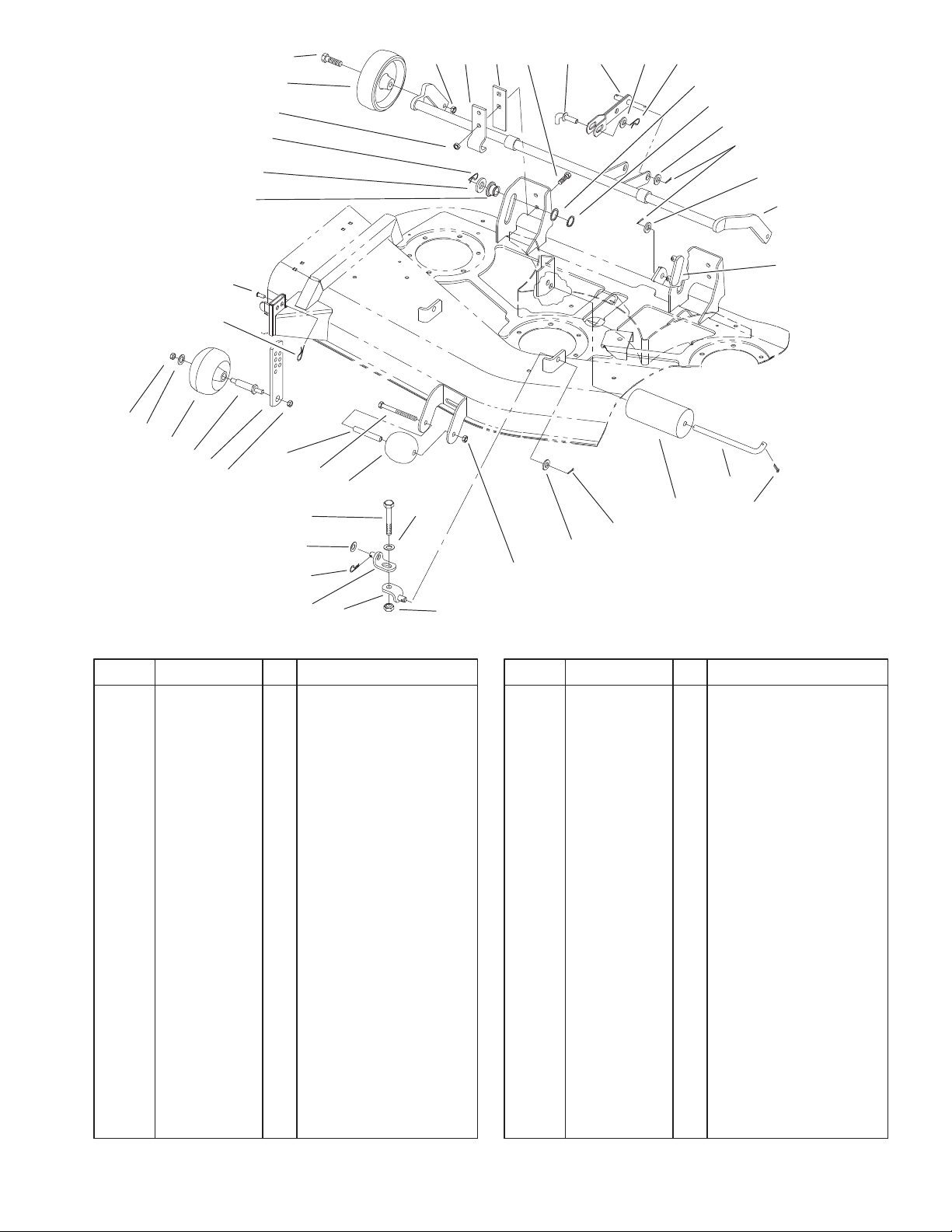
Gage Wheel And Lift Bracket Assembly
DescriptionPart No. Qty.Ref. No. DescriptionPart No. Qty.Ref. No.
1 92–1057 2 Bolt–Shoulder
2 92–6959 2 Wheel
3 32146–2 2 Nut–Lock, NI
4 110838–03 2 Bar
5 110837–03 2 Bracket–Pivot
6 323–7 4 Screw–HH
7 100–8734 1 Link Pin ASM
8 100–7503–03 1 Lift Arm ASM
9 3256–26 11 Washer–Flat
10 9335064 3 Pin–Hair Cotter
11 9202394 2 Washer
12 32151–29 2 Ring–Snap, External
13 3272–21 6 Pin–Cotter
14 100–6073–03 1 Wheel Carrier ASM
15 100–7501 1 Link Bracket–Rear
16 3272–11 2 Pin–Cotter
17 40–0340 2 Shaft–Roller, Rear
18 36–1740 2 Roller–Deck
19 3296–39 5 Nut–Lock, NI
20 325–13 2 Screw–HH
21 86–9240 2 Bracket–Lift, Lower
22 86–9250 2 Bracket–Lift, Upper
23 3218–5 2 Nut–Jam
24 29–4820 1 Roller
25 323–16 1 Screw–HH
26 94–2500 1 Tube – Wheel Spacer
27 100–8736 2 Plate–Gage Wheel
28 68–2730 2 Gage–Wheel
29 3256–24 2 Washer–Flat
30 9335054 2 Pin–Hair
31 283–2 2 Pin–Clevis
32 78–7340 2 Roller–Lift
33 3256–28 2 Washer–Flat
34 9335074 2 Pin–Hair
35 32128–21 4 Nut–HF
36 99–2842 2 Spacer–Wheel
3
 Loading...