

Toro 78280 Operator's Manual

Wheel
Horse
52” Mowers
for
FORM NO. 3322–354
Lawn
Model No. 78280– 9900001 & Up
& Garden T
ractors
Operator’s Manual
IMPORTANT: Read this manual carefully. It contains information about your
safety and the safety of others. Also become familiar with the controls and
their proper use before you operate the product.
Introduction
We want you to be completely satisfied with your
new product, so feel free to contact your local
Authorized Service Dealer for help with service,
genuine replacement parts, or other information you
may require.
Whenever you contact your Authorized Service
Dealer or the factory, always know the model and
serial numbers of your product. These numbers will
help the Service Dealer or Service Representative
provide exact information about your specific
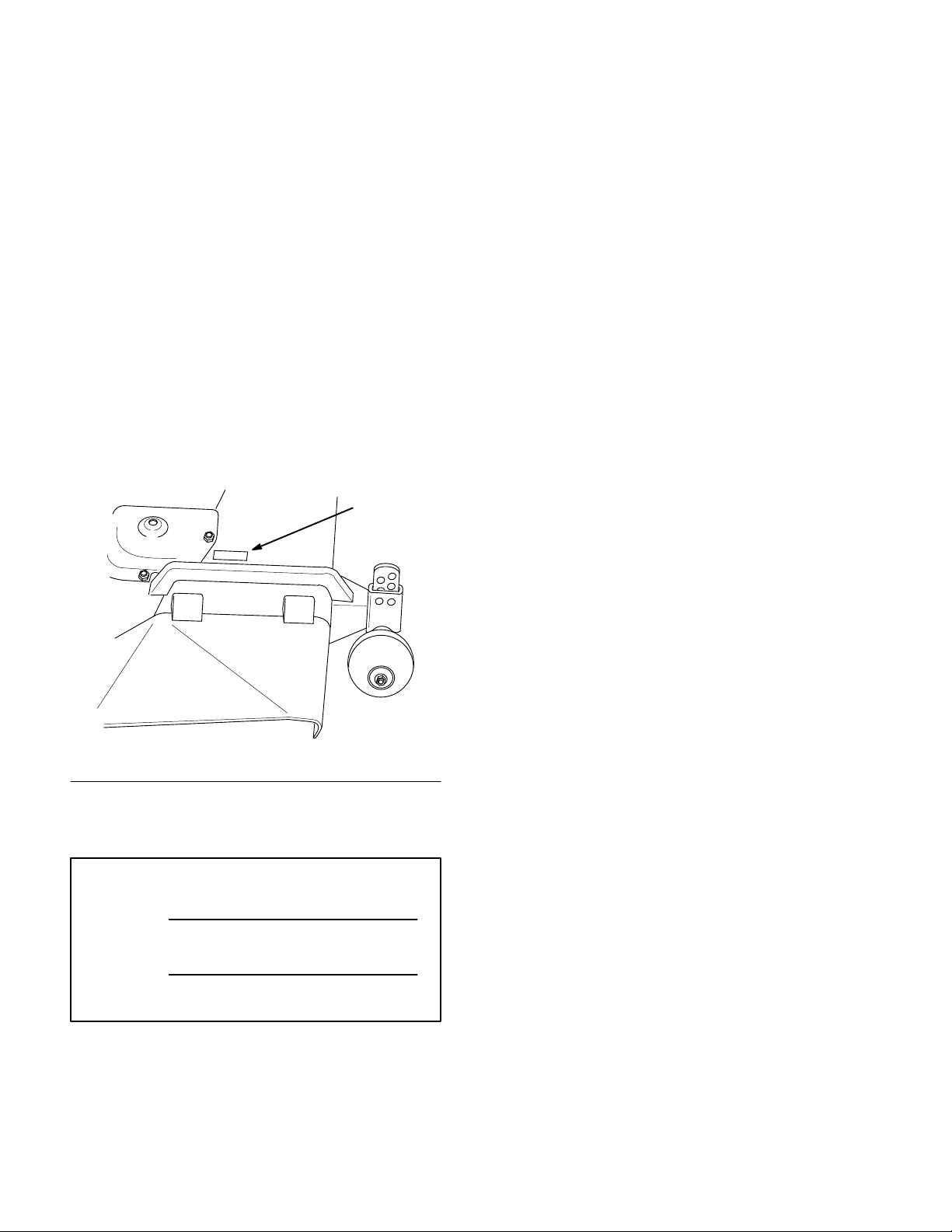
product. You will find the model and serial number
plate located in a unique place on the product as
shown below
.
1
The warning system in this manual identifies
potential hazards and has special safety messages that
help you and others avoid personal injury, even death.
DANGER, WARNING and CAUTION are signal
words used to identify the level of hazard. However,
regardless of the hazard, be extremely careful.
DANGER signals an extreme hazard that will cause
serious injury or death if the recommended
precautions are not followed.
WARNING signals a hazard that may cause serious
injury or death if the recommended precautions are
not followed.
CAUTION signals a hazard that may cause minor or
moderate injury if the recommended precautions are
not followed.
Two other words are also used to highlight
information. “Important” calls attention to special
mechanical information and “Note” emphasizes
general information worthy of special attention.
2371
1. Model
For your convenience, write the product model and
serial numbers in the space below.
Model No:
Serial No.
and Serial Number Plate
The left and right side of the machine is determined
by sitting on the seat in the normal operator’s
position.
Printed in USA
The Toro Company – 1997

Contents
Page
Safety and Instruction Decals 2.
Installation 3
Loose Parts 3
Mower Preparation 4
Tractor Preparation 6
Installing the Mower 7
Transport Height Adjustment 8
Side-to-Side Mower Leveling 8
Front-to-Rear Blade Slope 9
Removing the Mower 10
Installing RecyclingR Baf
Removing RecyclingR Baf
Operation 12
Side Discharge 12
Operating the
. . . . . . . . . . . . . . . . . . . . . . . . . . . . .
. . . . . . . . . . . . . . . . . . . . . . . . .
. . . . . . . . . . . . . . . . . . .
. . . . . . . . . . . . . . . . . . .
. . . . . . . . . . . . . . . . . . . . . . . . . . . . . .
. . . . . . . . . . . . . . . . . . . . . .
Power Take Off (PTO) 12
. . . . . . . . . . . . .
. . . . . . . . . . . . . . . . .
. . . . . . . . . . .
. . . . . . . . . .
. . . . . . . . . . . . .
. . . . . . . . . . . . . . . . .
fle 11
. . . . . . . . . . .
fle 11
. . . . . . . . . .
. . . . . . . . . . . . . .
Page
Attachment Lift Lever 13
Attachment Power Lift 13
Adjusting Dial-A-Height 14
Adjusting Anti-Scalp Wheels 14
Tips for Mowing Grass 15
Maintenance 16
Service Interval Chart 16
Cutting Blade17. . . . . . . . . . . . . . . . . . . . . . .
Greasing and Lubrication 19
Blade Drive Belt 19
Power Take Off (PTO) Belt 20
Washing Underside of Mower 20
Storage 22
Troubleshooting 23
. . . . . . . . . . . . . . . . . . . . . . . . . . . .
. . . . . . . . . . . . . . . . . . . . . . . . . . . .
. . . . . . . . . . . . . . . . . . . . . . . . .
. . . . . . . . . . . . . . . .
. . . . . . . . . . . . . . . .
. . . . . . . . . . . . . .
. . . . . . . . . .
. . . . . . . . . . . . . . .
. . . . . . . . . . . . . . . .
. . . . . . . . . . . . . .
. . . . . . . . . . . . . . . . . . . . .
. . . . . . . . . . . .
. . . . . . . . . .
1
Safety
Safety
ON GRASS DEFLECT
NEXT T
and Instruction Decals
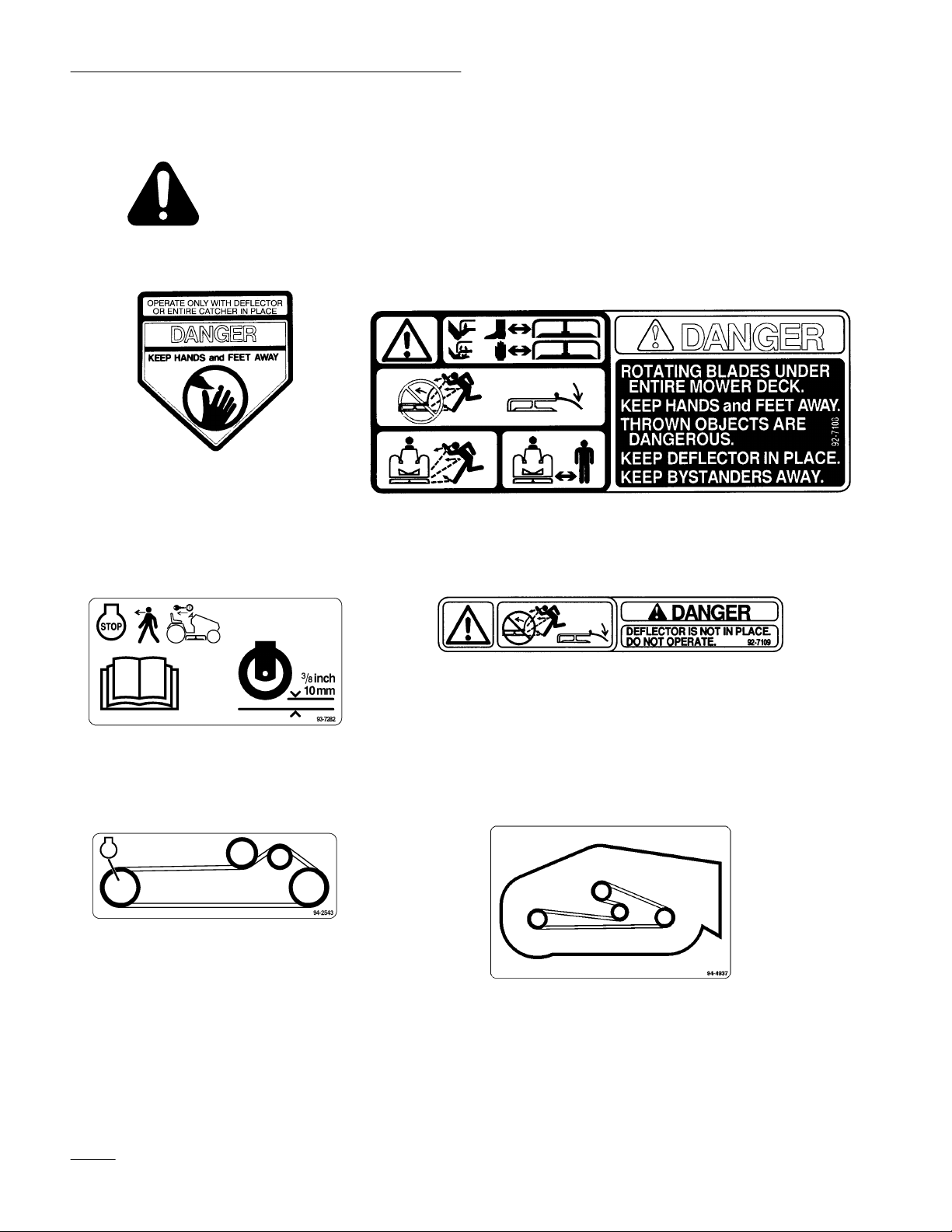
Safety decals and instructions are easily visible to the operator and are located near
any area of potential danger. Replace any decal that is damaged or lost.
OR
(Part No. 93–1
O GAGE WHEELS
(Part No. 93–7282)
122)
ON MOWER LEFT AND
DISCHARGE CHUTE
(Part No. 92–7108)
UNDER GRASS DEFLECT
(Part No. 92–7109)
OR
ON MOWER LEFT SIDE
(Part No. 94–2543)
2
ON MOWER REAR CENTER
(Part No. 94–4937)

Installation
Loose
Parts
Note: Use the chart below to identify parts used for assembly.
DESCRIPTION QTY. USE
Gage wheel
Shoulder bolt
Locknut 3/8–24 (with patch on threads)
Rear link
Washer 1/2” (13 mm)
Cotter pin 1” (26 mm)
Adjustable links
Washer 3/8” (10 mm)
Cotter pin 1” (26 mm)
Grass deflector
Spring
Bolt 3/8– 24 x 3-1/2” (89 mm)
Locknut 3/8–24
2
2
2
1
2
2
2
2
2
1
2
2
2
Install gage wheels
Install rear link
Install front mount to mower
Install grass deflector
Up stop
Hairpin cotter 3-3/8” (85 mm)
Washer 3/4” (19 mm)
Link pin
Hairpin cotter2-9/16” (65 mm)
Washer 1/2” (13 mm)
Operator’
Warranty card
s Manual
1
2
2
1
3
3
1
1
Install mower up stop
Install mower to tractor
Read before operating
3
Installation
Mower
Preparation
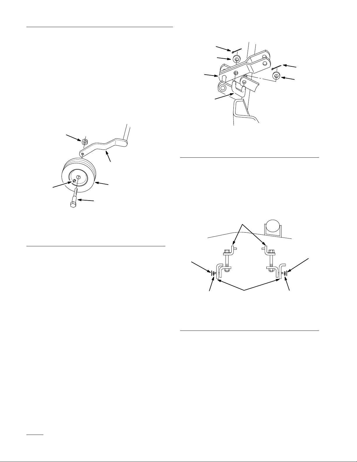
1. Attach gage wheels to the outside of arms on
rear carrier assembly. Grease fitting on wheel
must face out (Fig. 1).
2. Secure with shoulder bolt and 3/8” lock nut,
with internal locking patch on threads (Fig. 1).
Note:
3
Grease wheels.
5
1
2
4
m–2389
4
3
4
2
3
1
m–3388
Figure 2
1. Rear
2.
link
Carrier lift arm
3. W
asher 1/2”
4.
Cotter pin 1” (26 mm)
5. Rotate adjustable links so bolt heads are up and
place between brackets, as shown, on front of the
mower (Fig. 3).
6. Secure to brackets with 1/2” washers and 1”
(26 mm) cotter pins (Fig. 3).
Figure 1
1. Carrier
2. Wheel
3.
arm
Grease fitting out
4.
Shoulder bolt
5.
Lock nut 3/8” (with patch)
3. Install rear link between mower bracket and
carrier lift arm (Fig. 2).
4. Secure with 1/2” washers and 1” (26 mm) cotter
pins (Fig. 2).
1
4
m–3285
3
2
3
Figure 3
1. Adjustable
2. Bracket
link
asher 1/2”
3. W
4.
Cotter pin 1” (26 mm)
7. Place springs into brackets on mower with
hooked ends over raised back (Fig. 4).
8. Align grass deflector with holes in brackets and
spring straight ends in space under hinge and
above deflector (Fig. 4).
4
4
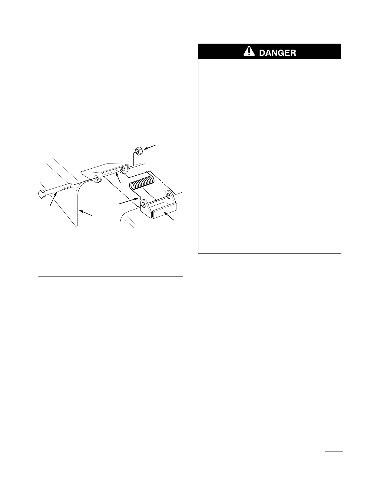
9. Secure deflector to bracket with 3/8–3-1/2 (89
mm) bolts through grass deflector, springs and
brackets. Secure with 3/8” lock nuts (Fig. 4).
10. Lift grass deflector and check that it is spring
loaded and pivots freely to the full down
position.
IMPORTANT: Grass deflector must be
spring loaded in the down position. Lift
deflector up to test that it snaps to the full
down position.
6
3
2
5
1. Bracket
2. Spring
3.
space for spring
hook end
4
Figure 4
4.
Grass deflector
5.
Bolt 3/8–3-1/2” (89 mm)
6.
Lock nut 3/8”
1783
Installation
POTENTIAL
HAZARD
• Without the grass deflector, discharge
cover, or complete grass catcher assembly
mounted in place, you and others are
exposed to blade contact and thrown
debris.
WHAT CAN HAPPEN
• Contact with rotating mower blade(s) and
thrown debris will cause injury or death.
HOW TO AV
•
NEVER r
OID THE HAZARD
emove the grass deflector from
the mower because the grass deflector
routes material down toward the turf. If the
grass deflector is ever damaged, replace it
immediately.
• Never put your hands or feet under the
mower.
• Never try to clear discharge area or mower
1
blades unless you move the power take off
(PTO) to “OFF” and rotate the ignition key
to “OFF.” Also remove the key and pull the
wire off the spark plug(s).
5

Installation
Tractor
Preparation
1. Park the machine on a level surface and lower
attachment lift to the full “DOWN” position.
Refer to Operation: Attachment Lift page 13.
Note: Turn Dial-A-Height control to allow
lift to go to full “MOUNTING”
position.
2. Adjust air pressure in tires to recommended
pressure.
3. Adjust transport height nut until bottom of rear
lift arms are approximately 7-1/4” (188 mm)
from the level surface (Fig. 5).
1
9. Slide lift rod into hole and secure with
previously removed washer and E-ring (Fig. 6).
10. Check that stop is 0”–1/8” (0–3 mm) away frame
when fully assembled and lift in the full “UP”
position.
5
4
2
1
Figure 6
4.
Lift link
5. Trunnion
m–3398
3
1. E-ring
2. Washer
2
3. Stop
on lift arm
3
Figure 5
1. Transport
2.
Rear lift arms
height nut
3.
7-1/4” (188 mm)
4. Raise attachment lift to the full “UP” position.
Refer to Operation: Attachment Lift page 13.
5. Remove E-ring, washer and lift link from front
lift arm (Fig. 6).
6. Hold front lift arm up until stop contacts frame
(Fig. 6).
7. Push back hard on lift rod, to raise linkage, and
check location of lift rod compared to mounting
hole location.
8. Adjust length of lift rod, by turning in\out of
trunnion, so end just slides into mounting hole in
front lift arm (Fig. 6).
11. Remove bolts securing existing up-stop to
tractor frame (Fig. 7).
12. Place J-clip, holding drain hose, against frame
and mount new, long, up-stop to frame with
previously removed hardware (Fig. 7).
2
3
1. Up-stop
2. J-clip
(long)
1
Figure 7
Existing bolts
3.
m–3390
6
Installation
Installing
the Mower
1. Park the machine on a level surface, disengage
the power take off (PTO), set the parking brake,
and turn the ignition key to “OFF” to stop the
engine. Remove the key.
2. Turn the front wheels straight ahead and raise
attachment lift lever all the way to the latched
position; refer to tractor Operator’
s Manual.
3. Slide the mower under tractor from right side,
turning front wheels as necessary. Align rear
mounting bushings with ends of lift arms.
4. Turn Dial-a-Height knob counterclockwise, all
the way, and lower attachment lift lever to the
mounting position; refer to Operation page 14.
5. Place rear guide bushings, first left side then
right, onto lift arms then slide deck left into
position (Fig. 8).
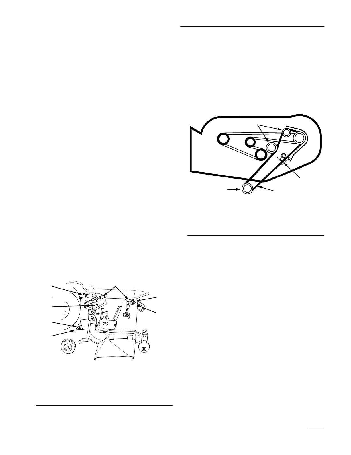
9. Pull on drive belt and rotate onto engine pulley
to install (Fig. 9).
Note: Make sure belt is properly located in
engine and deck pulleys and around
idler pulley.
10. Adjust belt guide so distance between belt and
guide is 1/8” (4 mm) (Fig. 9).
1
4
3
2
Figure 9
2418
6. Secure deck to rear lift arms with 3/4” washers
and large hairpin cotters (Fig. 8).
7. Install front adjustable links to front lift arms
with 1/2” washer and small hairpin cotter
(Fig. 8).
8. Attach rear link to attachment lift with link pin,
1/2” washer and small hairpin cotter (Fig. 8).
6
5
7
2
3
1. Lift
arm
2. W
asher 3/4”
3.
Hair pin cotter–large
4.
Attachment lift
Figure 8
4
1
5. W
asher 1/2”
6.
Hair pin cotter–small
7.
Link pin
6
5
m–2373
T
op V
iew
1. Idler
2.
pulley
Drive belt
3.
Engine pulley
4.
1/8” (4 mm)
11. Check mower level; refer to Side-to-Side Mower
Leveling page 8, and Front-to-Rear Blade
Leveling page 9.
12. Raise attachment lift lever all the way to the
latched position and adjust mower transport
height adjustment; refer to page 8.
7
 Loading...