

Page 1

Form No. 3327–580 Rev A
Quiet Collector
Wheel Horse Lawn and Garden Tractor
Attachment
Model No. 78200—Serial No. 220000001 and Up
Operator ’s Manual
English (GB)
Page 2

Contents
Page
Introduction 2. . . . . . . . . . . . . . . . . . . . . . . . . . . . . . . . .
Safety 3. . . . . . . . . . . . . . . . . . . . . . . . . . . . . . . . . . . . . .
Safety and Instruction Decals 4. . . . . . . . . . . . . . . . .
Setup 5. . . . . . . . . . . . . . . . . . . . . . . . . . . . . . . . . . . . . .
Loose Parts 5. . . . . . . . . . . . . . . . . . . . . . . . . . . . . . .
Installing the Quick Hitch 6. . . . . . . . . . . . . . . . . . .
Installing the Collector Drive 7. . . . . . . . . . . . . . . . .
Installing the Collector 8. . . . . . . . . . . . . . . . . . . . . .
Installing the Mower 9. . . . . . . . . . . . . . . . . . . . . . .
Installing the Boot Bracket 9. . . . . . . . . . . . . . . . . . .
Installing the Discharge Tubes 10. . . . . . . . . . . . . . . .
Installing the Decal 11. . . . . . . . . . . . . . . . . . . . . . . .
Installing the Front Wheel Weights 11. . . . . . . . . . . .
Operation 11. . . . . . . . . . . . . . . . . . . . . . . . . . . . . . . . . . .
Empty the Quiet Collector 11. . . . . . . . . . . . . . . . . . .
Holding the Collector Door Open 12. . . . . . . . . . . . .
Changing the Draft Control 12. . . . . . . . . . . . . . . . . .
Engaging the Quiet Collector PTO 12. . . . . . . . . . . .
Clearing Obstructions From the Collector 13. . . . . . .
Using the Full Collector Gauge 13. . . . . . . . . . . . . . .
Operating and Bagging Tips 13. . . . . . . . . . . . . . . . .
Removing the Collector 14. . . . . . . . . . . . . . . . . . . . .
Maintenance 15. . . . . . . . . . . . . . . . . . . . . . . . . . . . . . . . .
Recommended Maintenance Schedule 15. . . . . . . . .
Cleaning the Screen 15. . . . . . . . . . . . . . . . . . . . . . . .
Cleaning the Collector 15. . . . . . . . . . . . . . . . . . . . . .
Lubricating the Idler Arm 15. . . . . . . . . . . . . . . . . . .
Inspecting the Collector 15. . . . . . . . . . . . . . . . . . . . .
Inspecting the Mower Blades 15. . . . . . . . . . . . . . . . .
Storage 15. . . . . . . . . . . . . . . . . . . . . . . . . . . . . . . . . .
Troubleshooting 16. . . . . . . . . . . . . . . . . . . . . . . . . . . . . .
Introduction
Read this manual carefully to learn how to operate and
maintain your product properly. The information in this
manual can help you and others avoid injury and product
damage. Although Toro designs and produces safe
products, you are responsible for operating the product
properly and safely.
Whenever you need service, genuine Toro parts, or
additional information, contact an Authorized Service
Dealer or Toro Customer Service and have the model and
serial numbers of your product ready. Figure 1 illustrates
the location of the model and serial numbers on the
product.
1
m–5821
Figure 1
1. Location of the model and serial numbers
Write the product model and serial numbers in the space
below:
Model No.
Serial No.
This manual identifies potential hazards and has special
safety messages that help you and others avoid personal
injury and even death. Danger, Warning, and Caution are
signal words used to identify the level of hazard. However,
regardless of the hazard, be extremely careful.
Danger signals an extreme hazard that will cause serious
injury or death if you do not follow the recommended
precautions.
Warning signals a hazard that may cause serious injury or
death if you do not follow the recommended precautions.
Caution signals a hazard that may cause minor or moderate
injury if you do not follow the recommended precautions.
This manual uses two other words to highlight information.
Important calls attention to special mechanical
information and Note: emphasizes general information
worthy of special attention.
The following list contains safety information specific to
Toro products and other safety information you must know.
2002 by The Toro Company
8111 Lyndale Avenue South
Bloomington, MN 55420-1196
All Rights Reserved
Printed in the USA
2
Page 3

Safety
The following list contains safety information specific to
Toro products and other safety information you must know.
• Become familiar with the safe operation of the
equipment ant with the operator controls, and safety
signs.
• Use extra care with grass catchers or other attachments.
These can change the operating characteristics and the
stability of the machine.
• Follow the manufacturer’s recommendations for adding
or removing wheel weights or counterweights to
improve stability.
• Do not use a grass catcher on steep slopes. A heavy
grass catcher could cause loss of control or overturn the
machine.
• Slow down and use extra care on hillsides. Be sure to
travel in the recommended direction on hillsides. Turf
conditions can affect the machine’s stability. Use
extreme caution while operating near drop–offs.
• Keep all movement on slopes slow and gradual. Do not
make sudden changes in speed, directions or turning.
• The grass catcher can obstruct the view to the rear. Use
extra care when operating in reverse.
• Use care when loading or unloading the machine into a
trailer or truck
• Never operate with the discharge deflector raised,
removed or altered, unless using a grass catcher or
mulching baffles.
• Keep hands and feet away from moving parts. Do not
make adjustments with the engine running.
• Stop on level ground, disengage drives, chock or block
wheels, shut off engine before leaving the operator’s
position for any reason including emptying the grass
catcher or unclogging the chute.
• If you remove the grass catcher, be sure to install any
discharge deflector or guard that might have been
removed to install the grass catcher. Do not operate the
mower without either the entire grass catcher or the
grass deflector in place.
• Stop the engine before removing the grass catcher or
unclogging the chute.
• Do not leave grass in grass catcher for extended periods
of time.
• Grass catcher components are subject to wear, damage
and deterioration, which could expose moving parts or
allow objects to be thrown. Frequently check
components and replace with manufacturer’s
recommended parts, when necessary.
3
Page 4
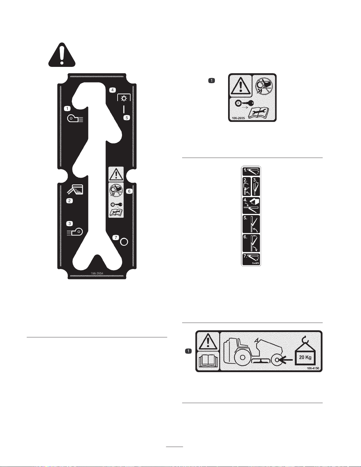
Safety and Instruction Decals
Safety decals and instructions are easily visible to the operator and are located near any area
of potential danger. Replace any decal that is damaged or lost.
106-2655
1. Warning—do not touch or approach moving belts; remove the
ignition key and read the instructions before servicing or
performing maintenance.
1. Blow left
2. Collect grass
3. Blow right
4. Power Takeoff (PTO)
5. On
106-2654
6. Warning—do not touch or
7. Off
approach moving belts;
remove the ignition key
and read the instructions
before servicing or
performing maintenance.
1. Squeeze the lever.
2. Raise the handle to the
dump position.
3. Release the lever.
4. Lower the handle to dump
the grass clippings.
106-4156
1. Warning—read the
weights (20 kg).
Operator’s Manual
98-3679
5. Return the handle to the
dump position.
6. Squeeze the lever and
lower the handle to the
operation position.
7. Release the lever.
; install front wheel
4
Page 5

Setup
Note: Determine the left and right sides of the machine
from the normal operating position.
Loose Parts
Note: Use the chart below to verify all parts have been shipped.
DESCRIPTION QTY. USE
Quick hitch
Tow hitch extension
Locknut, 1/2 in.
Locknut, 3/8 in.
Carriage Bolt, 3/8 x 1 in.
Carriage Bolt, 1/2 x 1–1/4 in.
Jack shaft assembly
Bolt, 1/4 x 1 in.
Locknut, 1/4 in.
Locknut, 5/16 in.
Engine pulley—double
Carriage Bolt, 5/16 x 1 in.
Shim
PTO stop
Bolt, 5/16 x 1–1/2 in.
Bolt, 7/16 x 5–1/2 in.
Lock washer, 5/16 in.
Collector
Dumping arm
Collector door
Knobs
Cotter pin, 3/16 x 1 in.
Clevis pin
Hairpin cotter pin
1
1
4
2
2
2
1
2
2
2
1
2
1
1
2
1
2
1
1
1
2
1
1
1
Installing the quick hitch
Installing the collector drive
Installing the collector
V–belt—drive
V–belt—collector
Template number 1 —42 in. (107 cm) mowers
Template number 2 —48 in. (122 cm) mowers
Boot bracket
Bolt, 1/4 x 1/2 in.
Flange nut, 1/4 in.
1
1
1
1
1
2
2
5
Installing the belts
Installing the boot bracket
Page 6
DESCRIPTION USEQTY.
Upper tube
Middle tube
Boot
Carriage bolt, 1/4 x 3/4 in.
Flange nut, 1/4 in.
Pin
Hairpin cotter pin
Decal 1 Installing the decal
Operator’s manual 1 Read before operation
1
1
1
3
3
1
1
Installing the discharge tubes
Installing the Quick Hitch
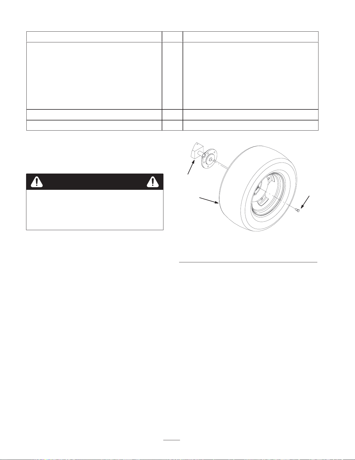
1. Raise the rear of the tractor and support with jack
stands.
Danger
Mechanical or hydraulic jacks may fail to support
machine and cause a serious injury.
• Use jack stand when supporting machine.
• Do not use hydraulic jacks.
2. Remove both rear tractor wheels (Fig. 2).
1
2
1. Tractor
2. Tire
3
m-5947
Figure 2
3. Lug
3. Install the quick hitch to the tractor using 2 carriage
bolts (3/8 x 1 in.) in the rear holes and secure with 2
locknuts (3/8 in.) (Fig. 3).
4. Install 2 carriage bolts (1/2 x 1–1/4 in.) in the front
holes. Secure bolts with 2 locknuts (1/2 in.) (Fig. 3).
6
Page 7
1
2
4
1
5
3
Figure 3
1. Carriage bolt, 3/8 x 1 in.
2. Lock nut, 3/8 in.
3. Carriage bolt, 1/2 x
1–1/4 in.
4. Lock nut, 1/2 in.
5. Quick hitch
5. Install the tow hitch extension to the tractor using 2
bolts (1/2 x 1–1/4 in.) and 2 locknuts (1/2 in.) (Fig. 4).
m–5966
2
3
4
21
5
m-5950
Figure 5
1. Bolt, 1/4 x 1 in.
2. Carriage Bolt, 5/16 x 1 in.
3. Locknut, 1/4 in.
4. Locknut, 5/16 in.
5. Jack shaft
3. Unplug the clutch terminal and remove the electric
clutch and the engine pulley (Fig. 8). Save the washer
and discard the bolt.
4. Remove the clutch stop from the frame of the machine
(Fig. 6).
1
3
2
m-5965
Figure 4
1. Bolt, 1/2 x 1–1/4 in.
2. Lock nut, 1/2 in.
3. Tow hitch extension
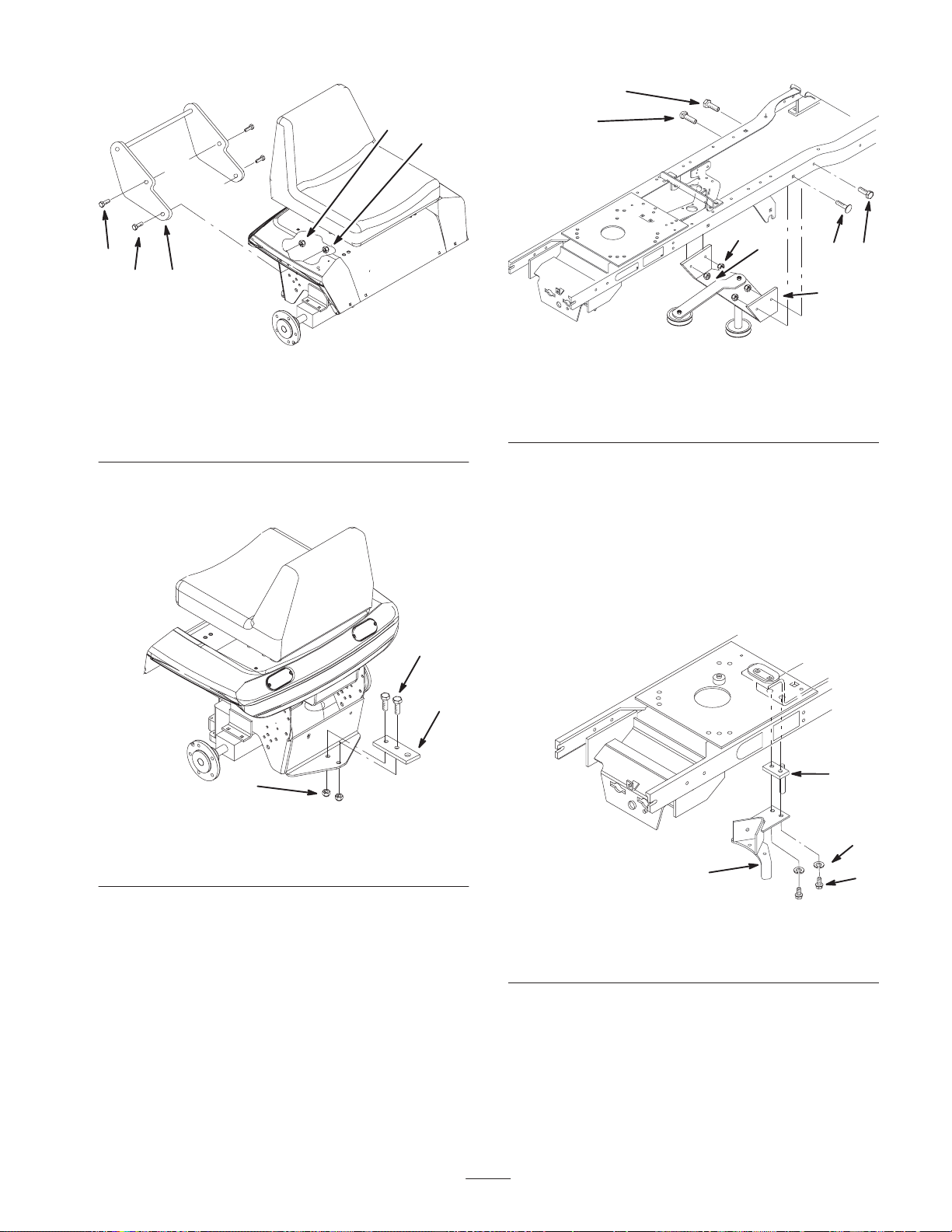
Installing the Collector Drive
1. Remove the mower . Refer to the mower operators
manual.
2. Install the jack shaft assembly inside the tractor frame
with 2 bolts (1/4 x 1 in.), 2 carriage bolts (5/16 x 1 in.),
2 locknuts (1/4 in.), and 2 locknuts (5/16 in.) (Fig. 5).
5. Install the new shim/upstop and clutch stop to the frame
with 2 bolts (5/16 x 1–1/2 in.) and 2 lockwashers (Fig.
6).
3
2
4
m-5948
1
Figure 6
1. Bolt, 5/16 x 1–1/2 in.
2. Lock washer, 5/16 in.
3. Shim/upstop
4. Clutch stop
6. Install the drive belt around the jack shaft pulley. Do not
put it around the drive belt idler (Fig. 7).
7. Loosely, install both the drive belt and transaxle belt
around the engine pulley (Fig. 7).
7
Page 8
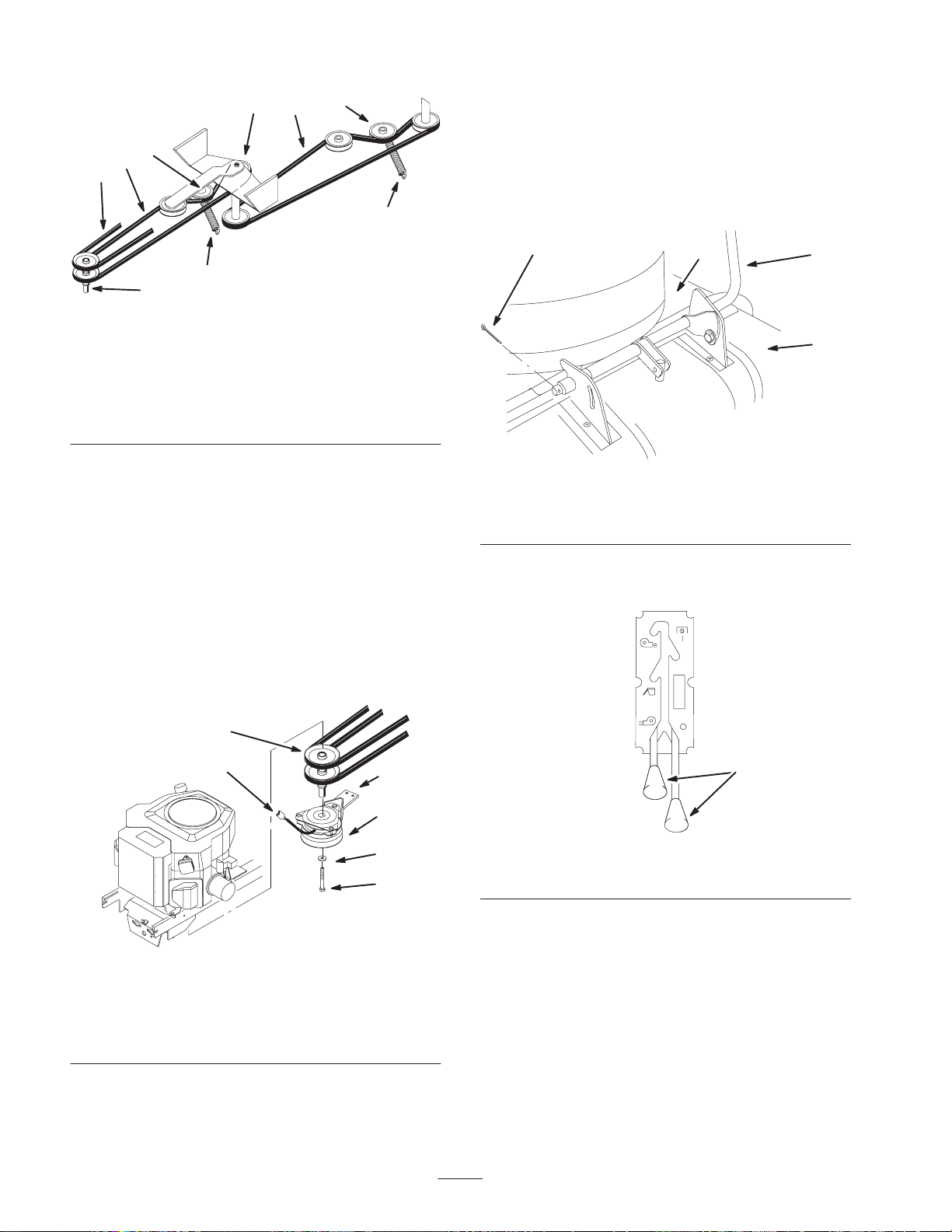
5
4
1
6
2
9
8
7
3
m-5959
Figure 7
1. Drive belt
2. Collector belt
3. Engine pulley
4. Drive belt idler pulley
5. Jack shaft pulleys
6. Collector belt idler pulley
7. Drive belt idler spring
8. Collector belt idler spring
9. Transaxle belt
Note: Use removable Loctite, or an equivalent thread
locker, on the new clutch bolt (7/16 x 5–1/2 in.).
8. Install the electric clutch and new engine pulley. Use
existing washer and new bolt (7/16 x 5–1/2 in.) (Fig. 8).
Installing the Collector
1. Align the hinges on both halves of the collector. The
halves must be positioned in the closed position
(Fig. 9).
2. Push the dumping arm through the hinges and secure
with a cotter pin (3/16 x 1 in.) (Fig. 9).
4
Figure 9
1. Dumping arm
2. Collector hopper
2
3. Collector door
4. Cotter pin
1
m-5956
3
9. Plug in the clutch terminal (Fig. 8).
10.Install the drive belt completely around all pulleys and
idler pulley (Fig. 7).
11. Install the drive belt idler spring (Fig. 7).
12.Install the transaxle belt completely around all pulleys
(Fig. 7).
3
5
6
4
2
1
m–5988
Figure 8
1. Hex bolt, 7/16 x 5–1/2 in.
2. Washer, previously
removed
3. Engine pulley
4. Electric clutch
5. Clutch terminal
6. Clutch stop
3. Install the oval knobs on the draft control and the
collector clutch control (Fig. 10).
1
m–5943
Figure 10
1. Knob
4. Place the quick hitch hooks, on the collector, over the
quick hitch round bar (Fig. 11).
5. Pull the hitch lever up. This will raise the hopper and
engage the collector pin into the hitch extension
(Fig. 11).
6. Pull locking pin out to allow the collector to be raised
into full upright position (Fig. 11).
7. When the collector is in upright position, release the
locking pin and lock collector in position (Fig. 11).
8
Page 9

8. Secure left side hitch hook with a clevis pin (3/8 x
1–1/2 in.) and a hairpin cotter (Fig. 11).
4. Center punch the 2 holes that are to be drilled and
remove the template (Fig. 12).
9. Install the collector belt onto the the jack shaft pulley
and fully install the collector belt (Fig. 7).
7
2
3
m–5953
6
4
1
8 9
5
Figure 11
1. Collector
2. Quick hitch hooks
3. Quick hitch round bar
4. Hitch lever
5. Locking pin
6. Clevis pin, 3/8 x 1–1/2 in.
7. Hairpin cotter
8. Collector pin
9. Hitch extension
Installing the Mower
For installing the mower, refer to the mower operator’s
manual.
5. Drill two, 9/32 in. diameter, holes at the marked
locations.
6. Install the boot bracket with 2 bolts (1/4 x 1/2 in.) and 2
flange nuts (1/4 in.) (Fig. 14).
Note: Install the bolt heads on top of the mower.
7. Install the belt guard (Fig. 12).
2
1
3
6
2 3
5
4
m-5963
Figure 12
1. Template
2. Hole to drill
3. Existing hole
4. Mower
5. Grass deflector
6. Belt guard
Important If extreme low cut height is used, install
mower drive belt in bottom engine pulley.
Installing the Boot Bracket
Note: There are two templates for installing the boot
bracket. Template number 1 is for 42 in. (107 cm) mowers
only and template number 2 is for 48 in. (122 cm) mowers
only.
Installing the Boot Bracket onto 42 in.
(107 cm) Mowers
Note: Use template number 1, in the back of this operator’s
manual, for locating holes to drill.
1. Locate and cut out template number 1 [42 in. (107 cm)
mower] as indicated on the template.
2. Remove the existing belt guard (Fig. 12).
3. Place template number 1 on top of the mower and align
it by matching the existing holes in the mower (Fig. 12).
Installing the Boot Bracket onto 48 in.
(122 cm) Mowers
Note: Use template number 2, in the back of this operators
manual, for locating holes to drill.
1. Locate and cut out template number 2 [48 in. (122 cm)
mower] as indicated on the template.
2. Remove the existing belt guard (Fig. 13).
3. Place template number 2 on top of the mower. Align it
so the notch in the template fits around the
reinforcement plate and the template matches the
existing hole (Fig. 13).
4. Center punch the 2 holes that are to be drilled and
remove the template (Fig. 13).
5. Drill two, 9/32 in. diameter, holes at the marked
locations.
6. Install the boot bracket with 2 bolts (1/4 x 1/2 in.) and 2
flange nuts (1/4 in.) (Fig. 14).
9
Page 10

Note: Install the bolt heads on top of the mower.
7. Install the belt guard (Fig. 13).
63
1
6
2
7
2 3
5
m–5964
4
Figure 13
1. Template
2. Hole to drill
3. Existing hole
4. Mower
5. Grass deflector
6. Re–enforcement plate
7. Belt guard
Installing the Discharge Tubes
1. Disengage the PTO and set the parking brake.
2. Stop the engine, remove the key, and wait for all
moving parts to stop before leaving the operating
position.
2
5
4
1
7
m-5962
Figure 14
1. Boot
2. Boot Pin
3. Hairpin cotter pin
4. Grass deflector
5. Boot bracket
6. Bolt, 1/4 x 1/2 in. and
flange nut, 1/2 in.
7. Slots in boot
6. Slide the middle tube onto the boot and latch them
together (Fig. 15).
7. Install the upper tube into the collector and onto the
middle tube (Fig. 15).
4
3
2
1
3. Lift the grass deflector all the way back. This will
eliminate interference with the boot (Fig. 14).
4. Align the boot with the boot bracket (Fig. 14).
5. Install the boot pin through the boot and boot bracket
and secure with a hair pin cotter (Fig. 14).
m-5945
Figure 15
1. Boot
2. Middle tube
3. Upper tube
4. Collector
8. Using the upper tube as a template, mark the hole
locations on the middle tube (Fig. 16).
9. Remove the upper tube and middle tube.
10.Drill 3 holes, 9/32 in. diameter, into the middle tube
(Fig. 16).
11. Install the middle and upper tube with 3 carriage bolts
(1/4 x 3/4 in.) and 3 flange nuts (1/4 in.) (Fig. 16).
Important Make sure the bolt heads are on the inside
of the middle tube.
12.Install the upper and middle tube to collector and boot.
(Fig. 15).
10
Page 11

Operation
4
5
1
3
2
Figure 16
1. Upper tube
2. Middle tube
3. Bolt, 1/4 x 3/4 in.
4. Flange nut, 1/4 in.
5. 9/32 in. hole
Installing the Decal
1. Clean an area on the left–hand tractor frame for the
decal (Fig. 17)
2. Install the decal on the tractor frame (Fig. 17)
m-5957
Note: Determine the left and right side of the machine from
the normal operating position.
Warning
To avoid personal injury, follow these procedures:
• Become familiar with all operating and safety
instructions in the operator’s manual for your
mower before using this attachment.
• Never remove the collector or collector tubes
while the engine is running.
• Always shut the engine off, remove the key, and
wait for all moving parts to stop before clearing
an obstruction from the bagging system.
• Never do maintenance or repairs while the
engine is running.
Warning
Without the grass deflector, collector tubes or
complete collector assembly mounted in place, you
and others are exposed to blade contact and
thrown debris. Contact with the rotating mower
blade(s) and thrown debris will cause injury or
death.
1
2
m-5950
Figure 17
1. Decal 2. Left–hand tractor frame
Installing the Front Wheel
Weights
Caution
The bagger adds a lot of weight to the rear of the
machine, causing a potential unstable condition
which could result in a loss of control.
• Install the front wheel weights.
Contact an Authorized Service Dealer for the correct front
wheel weights needed with the collector.
• Never remove the grass deflector from the
mower because the grass deflector routes
material down toward the turf. If the grass
deflector is ever damaged, replace it
immediately.
• Never put your hands or feet under the mower.
• Never try to clear the discharge area or mower
blades unless you move the power take off
(PTO) to off and rotate the ignition key to off.
Also remove the key and pull the wire off of the
spark plug(s).
Empty the Quiet Collector
1. Disengage the quiet collector PTO control (Fig. 20).
2. Disengage the mower PTO and set the parking brake.
Note: If the PTO is engaged, it is impossible to open the
collector due to the vacuum action inside.
3. Squeeze the collector lever on the collector arm
(Fig. 18).
11
Page 12

4. Raise the collector arm to the highest position and
release the collector lever (Fig. 18). The locking pin
will drop into a hole in the highest position.
3. Stop the engine, remove the key, and wait for all
moving parts to stop before leaving the operating
position.
5. Pull the collector arm down to raise the back of the
collector (Fig. 18).
6. Close the back of the collector and squeeze the collector
lever (Fig. 18).
7. Lower the collector arm to the working position
(Fig. 18).
Note: Make sure the collector door is fully sealed before
collecting grass.
2
1
m-5944
Figure 18
1. Collector lever 2. Collector arm
4. Open the collector; refer to Opening the Quiet
Collector, page 11.
5. With the collector open, pull out the holding pin and
insert into the hole in the hinge (Fig. 19).
2
3
Figure 19
1. Holding pin
2. Hole in hinge
3. Hinge
Changing the Draft Control
The draft control is located on the left side of collector.
There are three positions for the draft control; blow left,
blow right or collecting.
1. To blow right, move the draft control to the lowest
position (Fig. 20).
1
m-5961
Holding the Collector Door
Open
Warning
Hands, fingers and arms can get pinched between
the back and front sections of the collector.
• Keep people away from collector while
emptying it.
• If working on the inside, use the holding pin to
hold the collector door open.
1. Disengage the quiet collector PTO control (Fig. 20).
2. Disengage the mower PTO and set the parking brake.
2. For collecting grass, move the draft control to the
middle position (Fig. 20).
3. To blow left, move the draft control to the highest
position (Fig. 20).
Engaging the Quiet Collector
PTO
The PTO control is located on the left side of collector
(Fig. 20).
1. To engage the collector, move the PTO control to the
upper position. (Fig. 20).
2. To disengage the collector, move the PTO control to the
lowest position (Fig. 20).
12
Page 13

5
6
4
A. Raise the gauge arm frequently (Fig. 21). If you feel
resistance, it indicates the collector is full and needs
to be emptied.
B. If grass is seen building up in the slots, on top of the
boot (Fig. 14), the collector is full and needs to be
emptied. This can also mean that you are mowing
too fast and the boot is beginning to plug.
3
1
1. Collector Draft control
2. Collector PTO control
3. Blow right position
4. Collect grass position
Figure 20
5. Blow left position
6. Collector PTO engaged
7. Collector PTO
disengaged
7
2
m–5943
Clearing Obstructions From
the Collector
1. Empty the collector.
2. Disengage the quiet collector PTO control (Fig. 20).
3. Disengage the mower PTO and set the parking brake.
4. Stop the engine, remove the key, and wait for all
moving parts to stop before leaving the operating
position.
1
m-5946
Figure 21
1. Gauge arm
Operating and Bagging Tips
Size
Remember that the tractor is longer and wider with this
attachment installed. By turning too sharply in confined
places you may damage the attachment.
Trimming
Always trim with the left side of the mower. Do not trim
with the right side of the mower because you could damage
the collector’s blower and discharge tube.
5. Remove the upper tube and middle tube from the
collector.
6. Using a stick or similar object, carefully remove and
clear the obstruction from the mower, upper tube,
middle tube, or boot assembly.
7. After you remove the obstruction, install the complete
collector system and resume operation. Refer to
Installing the Discharge Tube on page 10.
Using the Full Collector Gauge
1. To determine when the collector is full, use the
following two methods.
Cutting Height
Do not set the mower cutting height too low because long
grass surrounding the mower can prevent air from getting
under the mower and entering the bagging system. If
enough air doesn’t get under the mower, the bagging
system will plug.
Cutting Frequency
Cut the grass often, especially when it grows rapidly. You
will have to cut your grass twice if it gets excessively long
(refer to Bagging Long Grass, page 14).
13
Page 14

Cutting Technique
For best lawn appearance, be sure to slightly overlap the
mower into the previously cut area. This helps reduce the
load on the engine and reduces the chance of plugging the
blower and discharge tube.
Also, grass may be seen building up inside the slot on top
of the boot.
Removing the Collector
1. Disengage the quiet collector PTO control (Fig. 20).
Bagging Speed
Most often you will bag with the tractor throttle in the fast
position and drive at a normal ground speed. However, in
extremely dry and dusty grass, you may want to slightly
reduce throttle speed and increase ground speed of the
tractor. The bagging system may plug if you drive too fast
and the engine speed gets too slow. On hills it may be
necessary to slow the tractor’s ground speed. This helps
maintain engine speed and bagging efficiency. Mow down
hill whenever possible.
Caution
As the collector fills, extra weight is added to the
back of the tractor. If you stop and start suddenly
on hills, you may lose steering control or the
tractor may tip.
• Do not start or stop suddenly when going uphill
or downhill. Avoid uphill starts.
• If you do stop the tractor when going uphill,
disengage the PTO (stop the mower blades) by
pushing the PTO control to off. Then back down
the hill using slow reverse speed.
• Do not change speeds or stop on slopes.
2. Empty the collector.
3. Disengage the mower PTO and set the parking brake.
4. Stop the engine, remove the key, and wait for all
moving parts to stop before leaving the operating
position.
5. Unlatch the middle tube from the boot (Fig. 15).
6. Remove the upper and middle tubes from the collector
(Fig. 15).
7. Remove the hairpin cotter pin and boot pin from the
boot bracket (Fig. 14).
8. Remove the boot from the mower and lower the grass
deflector (Fig. 14).
Warning
An uncovered discharge opening could allow the
lawn mower to throw objects in the operator’s or
bystander’s direction and result in serious injury.
Also, contact with the blade could occur.
Never operate the lawn mower unless you install a
grass deflector, a mulch plate, or discharge tubes
and bagger.
Bagging Long Grass
Excessively long grass is heavy and may not be propelled
completely into the collector. If this happens, the discharge
tube and blower may plug. To avoid plugging the bagging
system, mow the grass at a high height-of-cut, then lower
the mower to your normal cutting height and repeat the
bagging process.
Bagging Wet Grass
Always try to cut grass when it is dry because your lawn
will have a neat appearance. If you must cut wet grass, use
the conventional side discharge feature of the mower.
Several hours later, when the clippings are dry, install the
complete collector attachment and vacuum up the grass
clippings.
Signs of Plugging
As you are bagging, a small amount of grass clippings
normally blow out the front of the mower. An excessive
amount of clipping blow-out indicates that the collector is
full or the system is plugged.
9. Remove the collector belt.
10.Remove the clevis pin and hairpin cotter from the left
side of the collector (Fig. 11).
11. Unlatch the locking pin on the right–hand side of the
collector (Fig. 11).
12.Remove the collector from the quick hitch (Fig. 11).
13.Remove the front wheel weights.
14
Page 15

Maintenance
Note: Determine the left and right side of the machine from the normal operating position.
Recommended Maintenance Schedule
Maintenance Service
Interval
Each Use • Screen—clean
10 Hours • Collector—clean
40 Hours
Storage Service
Maintenance Procedure
• Collector—check belt tension
• Collector—inspect
• Collector idler arms—oil/lubricate
• Collector idler arms—oil/lubricate
• Belts—check for wear/cracks
• Collector—belt tension
• Collector—clean and inspect
Cleaning the Screen
The screen needs to be cleaned every 10 hours. In wet grass
it will need to be cleaned more often.
1. Disengage the PTO and set the parking brake.
2. Stop the engine, remove the key, and wait for all
moving parts to stop before leaving the operating
position.
3. Open the collector and hold the collector door open.
Refer to Holding the Collector Door Open on page 12.
4. Clean the debris from the screen.
5. Close the collector door.
Inspecting the Collector
Inspect the collector attachment every 40 hours of
operation.
1. Disengage the power take off (PTO), set the parking
brake, turn the ignition key to off and remove the key.
2. Check the upper tube, middle tube, and the boot
assembly. Replace these parts if they are cracked or
broken.
3. Check the collector and screens. Replace any parts that
are cracked or broken.
4. Tighten all nuts bolts and screws.
Cleaning the Collector
The collector needs to be cleaned after each use.
1. Wash the inside and outside of the collector, upper tube,
middle tube, boot assembly and the underside of the
mower. Use a mild automotive detergent to remove dirt.
2. Make sure you remove matted grass from all parts.
3. After washing all parts, let them dry thoroughly.
Lubricating the Idler Arm
Lubricate the collector belt idler arms every 40 hours.
Inspecting the Mower Blades
1. Inspect the mower blades regularly and whenever a
blade strikes a foreign object.
2. If blades are badly worn or damaged, install new blades.
Refer to your mower operator’s manual for complete
blade maintenance.
Storage
1. Clean the collector attachment. Refer to Cleaning
Obstructions from the Collector on page 13.
2. Inspect the collector attachment for damage. Refer to
Inspecting the Collector on page 15.
3. Make sure the collector is empty and thoroughly dry.
4. Check the belt for wear or cracks.
15
Page 16

5. Store the machine in a clean, dry place, out of direct
gqy
sunlight. This protects the plastic parts and extends the
life of the machine. If you must store the machine
outside, cover it with a weatherproof cover.
Troubleshooting
Problem Possible Causes Corrective Action
Abnormal vibration.
Reduced bagging performance.
1. Cutting blade(s) is/are bent or
unbalanced.
2. Blade mounting bolt is loose. 2. Tighten blade mounting bolt.
3. Loose collector pulley or
pulley assembly.
4. Collector belt is worn or
damaged.
5. Bagger impeller is out of
balance.
1. Low engine speed. 1. Always operate the collector at
2. Plugged fan screen. 2. Remove debris, leaves or grass
3. Loose collector belt. 3. Check the collector belt
4. Broken seal between hopper
and rear door.
5. A plugged boot. 5. Locate and remove plugged
6. Improper seal around the upper
tube going into the hopper.
1. Install new cutting blade(s).
3. Tighten the appropriate
pulley.
4. Replace the collector belt.
5. Contact Authorized Service
Dealer.
full throttle.
clippings from the fan screen.
tension.
4. Ensure the rear door is latched.
debris.
6. Ensure that there is a good
seal at hopper.
Boot and tubes plug too frequently.
Debris blowout.
7. Full hopper. 7. Empty hopper.
1. Hopper is too full. 1. Dump more frequently.
2. Grass is too wet. 2. Cut grass when dry.
3. Grass is too long. 3. Cut the grass twice. Once in a
high height–of–cut and next in
a normal height.
4. Plugged fan screen. 4. Remove debris, leaves or grass
clippings from the fan screen.
5. Ground speed is to fast. 5. Drive slower at full throttle.
1. Hopper is too full. 1. Dump more frequently.
2. Ground speed is to fast. 2. Drive slower at full throttle.
3. Grass build up on slots in boot. 3. Drive slower at full throttle or
the collector is full.
16
Page 17

17
Page 18
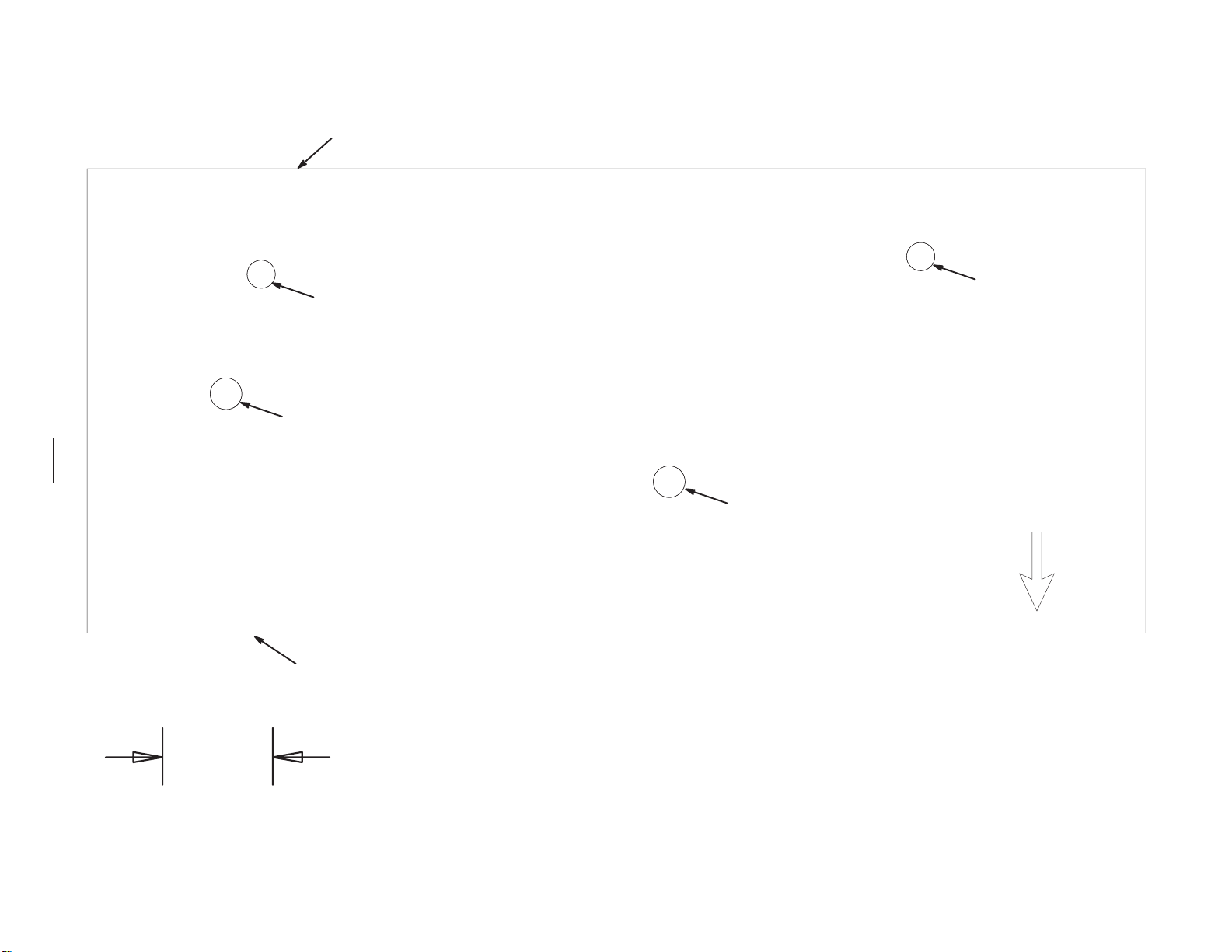
Cut out template here
Template No. 1
18
Scale
Existing Hole
Drill a 9/32 in.
hole here.
Cut out template here
42 in. (107 cm) mower
template
Drill a 9/32 in.
hole here.
Existing Hole
Towards Side
Discharge
1 inch
26 mm
Template No. 1
Page 19

19
Page 20

Align this edge with the re–
enforcing plate on top of the
mower
Cut out template here
Drill a 9/32 in. hole here.
20
Drill a 9/32 in. hole here.
Cut out template here
Existing Hole
Template No. 2
48 in. (122 cm) mower
template
Template No. 2
Towards Side
Discharge
Scale
1 inch
26 mm
Page 21

212223
Page 22

Page 23

Page 24

24
 Loading...