

Page 1

Form No. 3357-627 Rev. A
Operator’s Manual
Mulch Kit
For 600-series tractors with a 38-inch or 42-inch Deck
Models
77210
190-116
MTD PRODUCTS INC. P.O. BOX 368022 CLEVELAND, OHIO 44136-9722
PRINTED IN U.S.A.
FORM NO.
770-10435.fm
(8/2000)
Page 2
SECTION 1: TO THE OWNER
The Model 116 mulch kit replaces the Model 112 kit. It is designed for use with 38-inch or 42-inch cutting decks on
600-series lawn tractors manufactured after 1996 ONLY. It will NOT fit on tractors with decks made in 1996 or prior.
If you should own such a tractor and would like to convert the deck to a mulcher, purchase kit OEM-190-096 (38inch decks) or kit OEM-190-097 (42-inch decks). If you are unsure of the exact manufacturing date of your tractor,
you may contact the Customer Support department by dialing 1(800) 800-7310. Have your tractor’s model number
and serial number ready for prompt service.
NOTE: References to LEFT and RIGHT indicate the left and right sides of the tractor when facing forward in the
operator’s position. Reference to the FRONT indicates the grille end; to the REAR the drawbar end.
SECTION 2: CONTENTS OF CARTON
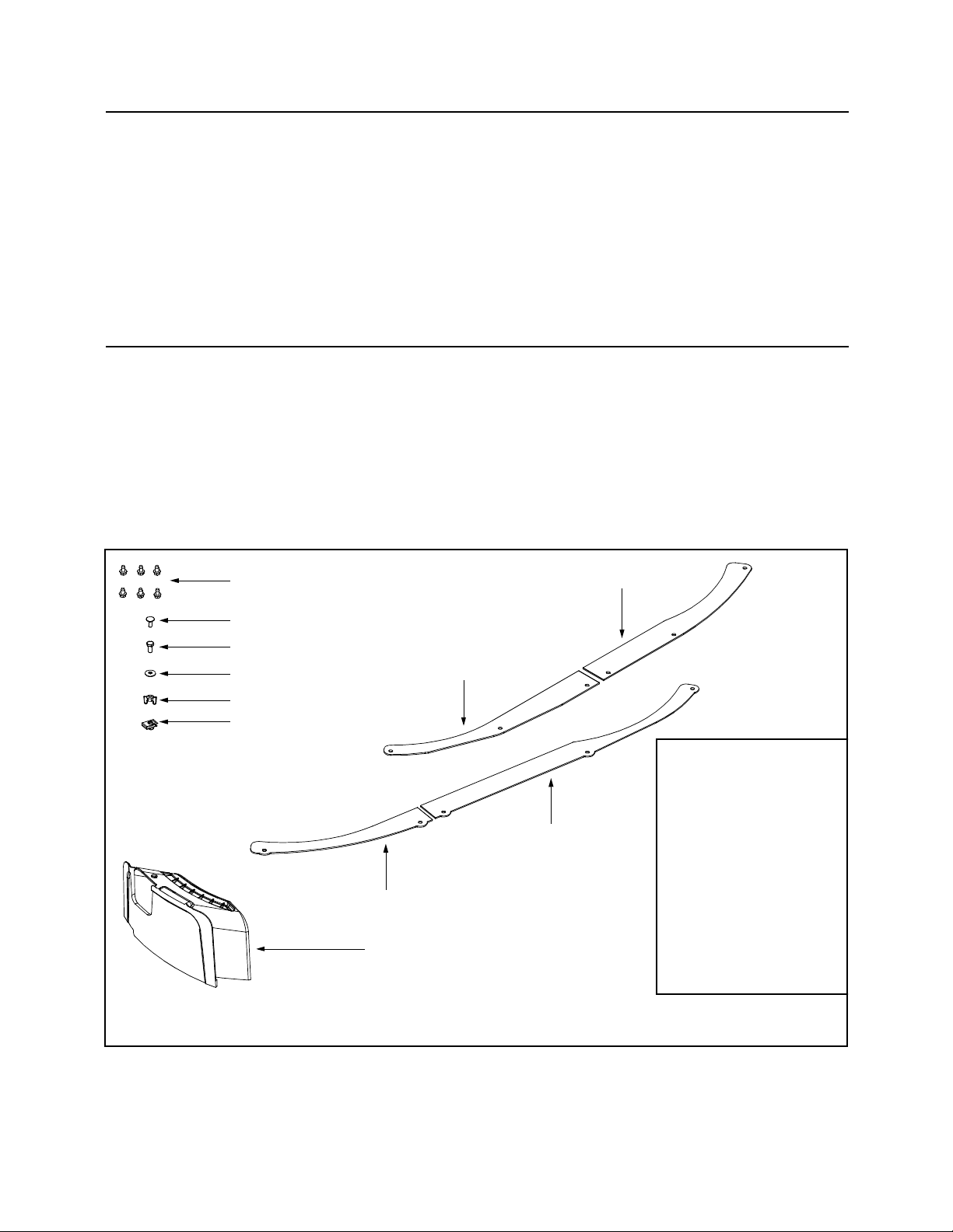
Before beginning installation, remove all parts from the carton and compare them to Figure 1. Carton contents are
listed below with part numbers in parentheses. Tools required for kit installation are listed in the inset of Figure 1.
One Mulch Plug (731-2363)
One LH Skirt for 38-inch Decks (783-1300)
One RH Skirt for 38-inch Decks (783-1299)
One LH Skirt for 42-inch Decks (783-1258A)
One RH Skirt for 42-inch Decks (783-1259A)
Six 1/4-20 x .5 Self-tapping Screws (710-0599)
One 1/4-20 x .6 Carriage Screw (710-0134)
One 1/4-20 x .6 Hex Screw (710-0751)
One Bell Washer (736-0270)
One 1/4-20 Plastic Wing Nut (712-3087)
One Mulch Plug Drill Guide (726-0211)
Self-tapping Screws
LH Skirt (38-inch decks)
Carriage Screw
Hex Screw
Bell Washer
RH Skirt (38-inch decks)
Plastic Wing Knob
Drill Guide
LH Skirt (42-inch decks)
RH Skirt (42-inch decks)
Mulch Plug
NOTE: The numeral “38” is stamped into the BOTTOM of each deck skirt to be used on 38-inch decks.
Conversely, the numeral “42” is stamped into the TOP of each deck skirt to be used on 42-inch decks.
Tools Required
Socket Wrench (Ratchet)
3/8” Socket
†7/16” Socket
†Hammer
† Center Punch or Large Nail
† C-clamps or Locking Pliers
† Electric Drill
† 1/8-inch Metal Drill Bit
† 7/32-inch Metal Drill Bit
† 9/32-inch Metal Drill Bit
Necessary only when installing
†
the mulch kit on an older-style
(1997-2000)cutting deck.
Figure 1
NOTE: Due to the fact that OEM-190-116 mulch kit is designed for use on both 38-inch cutting decks and 42-inch
cutting decks, not all of the contents of the carton will be used for your tractor’s deck application.
2
Page 3
SECTION 3: INSTALLING THE MULCH KIT
NOTE: Tractors with older-style cutting decks
(manufactured between 1997 and 2000) do NOT have
holes pre-drilled for mounting the mulch plug and deck
skirts. All tractors manufactured in 2001 or later will
have pre-drilled holes in the cutting deck.
Installing the Mulch Plug
The following instructions apply to both 38-inch cutting
decks and 42-inch cutting decks.
Tractor’s Manufactured in 2001 or later (with pre-drilled holes)
1. Locate the square hole found in the cutting deck
surface by pivoting the discharge chute upward.
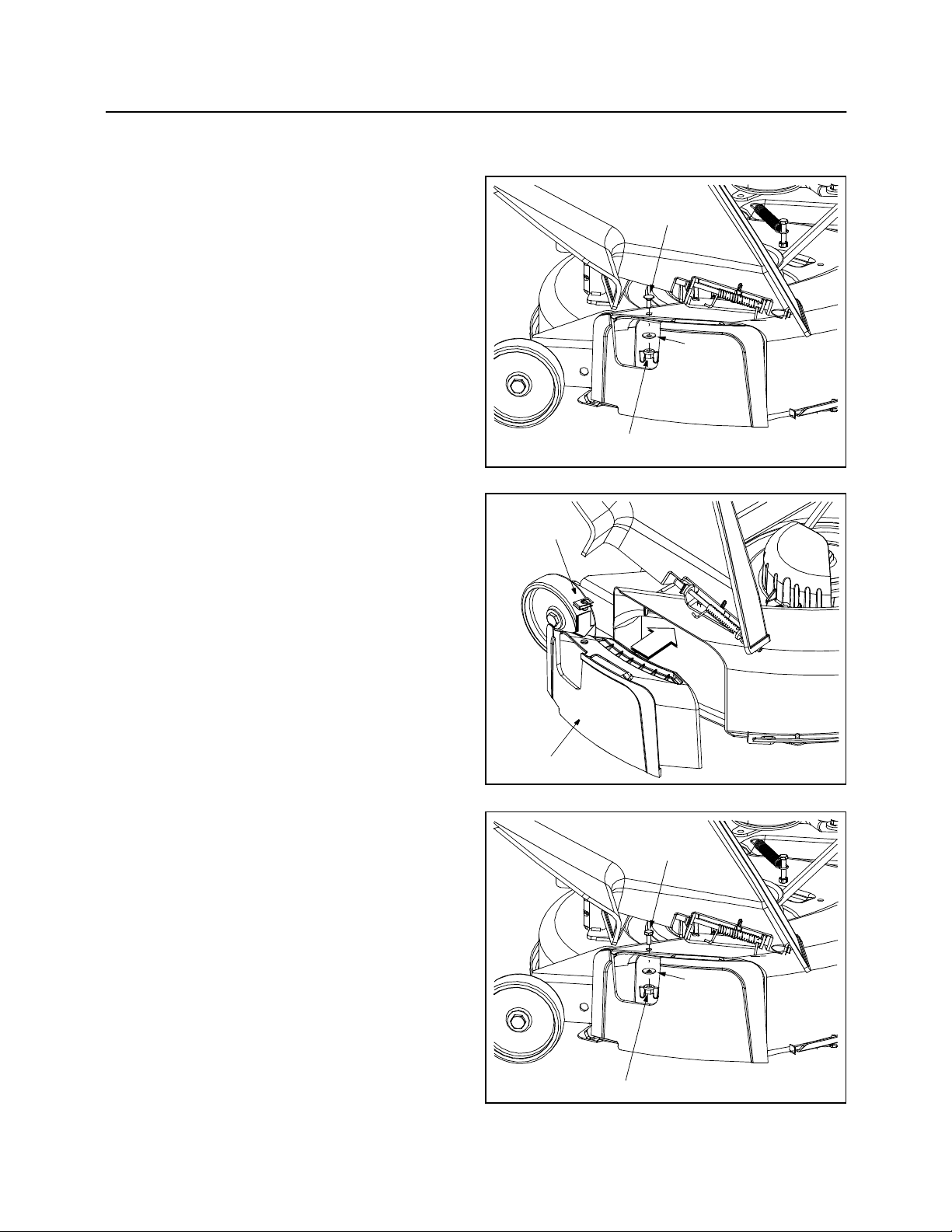
2. Install the mulch plug and secure it in place with the
carriage screw, bell washer and plastic wing nut as
illustrated in Figure 2.
Tractor’s Manufactured Prior to 2001 (without pre-drilled holes)
1. Place the mulch plug drill guide included with this
kit in place on the surface (NOT over the lip) of the
mulch plug as shown in Figure 3.
2. Pivot the discharge chute upward and place the
mulch plug (with the drill guide still resting in the
hole on its surface) inside the discharge chute
opening. The drill guide will slide smoothly over the
top lip of the discharge chute opening.
3. Mark the location on the cutting deck surface
through the drill guide opening with a hammer and
center punch or large nail.
4. Remove the mulch plug and discard the drill guide.
5. Using a 1/8” bit, carefully drill a pilot hole into the
cutting deck surface where the mark was made in
the step 3.
6. Using a 9/32” bit, carefully drill out the pilot hole just
made.
7. Reposition the mulch plug in place over the
discharge chute opening and fasten it with the hex
screw, bell washer and plastic wing nut as
illustrated in Figure 4.
8. Secure the mulch plug by snugging the hex screw
(NOT one of the self-tapping screws) with a 7/16inch wrench.
Drill Guide
Mulch Plug
Carriage Screw
Bell
Washer
Plastic Wing Nut
Figure 2
Figure 3
Hex Screw
Bell
Washer
Plastic Wing Nut
Figure 4
3
Page 4

Attaching the Deck Skirts
38-inch Decks
The following instructions are for the installation of the mulch kit on tractor’s equipped with a 38-inch deck only. If
your tractor is equipped with a 42-inch deck, disregard these instructions and skip to the instructions on page 6
under the heading 42-inch Decks.
WARNING: Before attempting to install the mulch kit, move the machine to flat, level ground, disengage
PTO, shift to neutral, set parking brake, stop engine and remove key to prevent unintended starting.
WARNING: Always wear safety glasses before performing the following instructions.
NOTE: On tractor’s with pre-drilled holes along the cutting deck’s front lip, it is easier, but NOT necessary, to
remove the cutting deck from the tractor in order to complete the following steps.
1. Remove the cutting deck as instructed in your tractor’s Operator’s Manual.
2. Carefully flip the cutting deck over to expose its underside.
3. Clean all debris from the underside of the deck, specifically the area near the front edge.
4. Position the deck skirt segments over the front edge of the cutting deck as illustrated in Figure 5. Use locking
pliers or C-clamps to secure the skirt segments in place.
NOTE: On newer-style tractor decks (manufactured in 2001 or later), holes are drilled into the deck at the factory
that will align with the holes found in the deck skirt segments.
IMPORTANT:
operating position). Be certain that the stamped side is facing you when positioning the skirt segments over the
front edge of the cutting deck, with the deck flipped upside down.
5. On tractor’s without pre-drilled holes, use a hammer and center punch (or large nail) to mark the six locations
where it will be necessary to drill holes into the cutting deck.
6. Using a 1/8” bit, carefully drill pilot holes into the cutting deck where the six center-punch marks were made in
the step 5.
7. Using a 7/32” bit, carefully drill out the pilot holes just made.
8. Fasten the LH skirt segment in place over the front edge of the cutting deck with three self-tapping screws.
IMPORTANT:
deck when it’s in its operating position.
9. Fasten the RH skirt segment in place over the front edge of the cutting deck with the three remaining selftapping screws.
10. Release the clamping pliers or C-clamps from the cutting deck and set them aside.
11. Secure both skirt segments by tightening all six screws with a 3/8-inch wrench.
The numeral “38” is stamped into the BOTTOM of each deck skirt segment (when viewed in its
Be certain to fasten the deck skirt so that the heads of the screws are on the underside of the cutting
4
Page 5
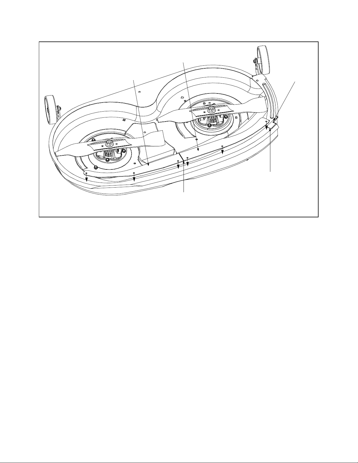
38-inch Decks
Right-hand Skirt Segment
IMPORTANT:
Left-hand Skirt Segment
Make Sure that the RH skirt segment
butts flushly up against the toe guard.
Make Sure that the deck segments
butt flushly up against each other.
Line up the deck skirts evenly along the edge of the cutting deck’s front lip.
Figure 5
Toe Guard
5
Page 6

Attaching the Deck Skirts
42-inch Decks
The following instructions are for the installation of the mulch kit on tractor’s equipped with a 42-inch deck only. If
your tractor is equipped with a 38-inch deck, disregard these instructions and refer to the previous instructions on
page 4 under the heading 38-inch Decks.
WARNING: Before attempting to install the mulch kit, move the machine to flat, level ground, disengage
PTO, shift to neutral, set parking brake, stop engine and remove key to prevent unintended starting.
WARNING: Always wear safety glasses before performing the following instructions.
NOTE: On tractor’s with pre-drilled holes along the cutting deck’s front lip, it is easier, but NOT necessary, to
remove the cutting deck from the tractor in order to complete the following steps.
1. Remove the cutting deck as instructed in your tractor’s Operator’s Manual.
2. Carefully flip the cutting deck over to expose its underside.
3. Clean all debris from the underside of the deck, specifically the area near the front edge.
4. Position the deck skirt segments over the front edge of the cutting deck as illustrated in Figure 6. Use locking
pliers or C-clamps to secure the skirt segments in place.
NOTE: On newer-style tractor decks (manufactured in 2001 or later), holes are drilled into the deck at the factory
that will align with the holes found in the deck skirt segments.
IMPORTANT:
position). Be certain that the stamped side is facing away from you when positioning the skirt segments over the
front edge of the cutting deck, with the deck flipped upside down.
5. On tractor’s without pre-drilled holes, use a hammer and center punch (or large nail) to mark the six locations
where it will be necessary to drill holes into the cutting deck.
6. Using a 1/8” bit, carefully drill pilot holes into the cutting deck where the six center-punch marks were made in
the step 5.
7. Using a 7/32” bit, carefully drill out the pilot holes just made.
8. Fasten the LH skirt segment in place over the front edge of the cutting deck with three self-tapping screws.
IMPORTANT:
deck when it’s in its operating position.
9. Fasten the RH skirt segment in place over the front edge of the cutting deck with the two remaining self-tapping
screws.
10. Release the clamping pliers or C-clamps from the cutting deck and set them aside.
11. Secure both skirt segments by tightening all six screws with a 3/8-inch wrench.
The numeral “42” is stamped into the TOP of each deck skirt segment (when viewed in its operating
Be certain to fasten the deck skirt so that the heads of the screws are on the underside of the cutting
6
Page 7
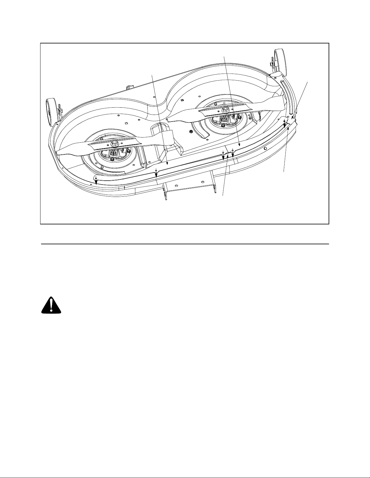
42-inch Decks
IMPORTANT:
Line up the deck skirts evenly along the edge of the cutting deck’s front lip.
Right-hand Skirt Segment
Left-hand Skirt Segment
Toe Guard
Make Sure that the RH skirt segment
butts flushly up against the toe guard.
Make Sure that the deck segments
butt flushly up against each other.
Figure 6
SECTION 4: USING THE MULCH KIT
This mulch kit incorporates special blades, already standard on your tractor’s cutting deck, in a process of
recirculating grass clippings repeatedly beneath the cutting deck. After which, the ultra-fine clippings are forced
back into the lawn where they act as a natural fertilizer. Observe the following recommendations for the best results
when mulching.
WARNING: Follow all safety warnings and instructions in your tractor’s Operator’s Manual before
operating.
• Never attempt to mulch if the lawn is damp. Wet grass tends to stick to the underside of the cutting deck
preventing proper mulching of the clippings.
• Do NOT attempt to mulch more than 1/3 the total height of the grass or approximately 1-1/2 inches. Doing so
will cause the clippings to clump up beneath the deck and not be mulched effectively.
• Maintain a slow ground speed to allow the grass clippings more time to effectively be mulched.
• For effective mulching, position the throttle control in the FAST (rabbit) position and allow it to remain there
while mowing. Failing to keep the engine at full throttle places strain on the tractor’s engine and does not
allow the blades to properly mulch grass.
NOTE: It is not necessary to remove the discharge chute to operate the mower with the mulch kit installed. It is
also unnecessary to remove the deck skirts should you choose to operate the mower without the mulch plug
installed. Simply remove the mulch plug and allow the clippings to discharge as you normally would.
7
Page 8

MANUFACTURER’S
LIMITED WARRANTY
The limited warranty set forth below is given by MTD
PRODUCTS INC (“MTD”) with respect to new merchandise
purchased and used in the United States, its possessions
and territories.
MTD warrants this product against defects in material and
workmanship for a period of two (2) years commencing on
the date of original purchase and will, at its option, repair or
replace, free of charge, any part found to be defective in
material or workmanship. This limited warranty shall only
apply if this product has been operated and maintained in
accordance with the Operator’s Manual furnished with the
product, and has not been subject to misuse, abuse, commercial use, neglect, accident, improper maintenance,
alteration, vandalism, theft, fire, water or damage because
of other peril or natural disaster. Damage resulting from the
installation or use of any accessory or attachment not
approved by MTD Products Inc. for use with the product(s)
covered by this manual will void your warranty as to any
resulting damages.
Normal wear parts or components thereof are subject to
separate terms as follows: All normal wear part or component failures will be covered on the product for a period of
90 days regardless of cause. After 90 days, but within the
two year period, normal wear part failures will be covered
ONLY IF caused by defects in material or workmanship of
OTHER component parts. Normal wear parts and components include, but are not limited to, belts, blades, blade
adapters, grass bags, rider deck wheels, seats, snow
thrower skid shoes, shave plates and tires. Batteries are
covered by a 90-day limited replacement warranty.
HOW TO OBTAIN SERVICE: Warranty service is available,
WITH PROOF OF PURCHASE THROUGH YOUR LOCAL
AUTHORIZED SERVICE DEALER. To locate the dealer in
your area, please check for a listing in the Yellow Pages or
contact the Customer Service Depar tment of MTD PRODUCTS INC by calling 1-800-800-7310 or writing to P.O. Box
368022, Cleveland, Ohio 44136-9722.
This limited warranty does not provide coverage in the
following cases:
a. The engine or component parts thereof. These items
carry a separate manufacturer’s warranty. Please refer
to the applicable manufacturer’s warranty on these
items.
b. Log splitter pumps, valves and cylinders have a sepa-
rate one year warranty.
c. Routine maintenance items such as lubricants, filters,
blade sharpening and tune-ups, or adjustments such
as brake adjustments, clutch adjustments or deck
adjustments; and normal deterioration of the exterior
finish due to use or exposure.
d. MTD does not extend any warranty for products sold
or exported outside of the United States of America,
its possessions and territories, except those sold
through MTD’s authorized channels of export distribu-
tion.
No implied warranty, including any implied warranty of
merchantability or fitness for a particular purpose,
applies after the applicable period of express written
warranty above as to the parts as identified. No other
express warranty or guaranty, whether written or oral,
except as mentioned above, given by any person or
entity, including a dealer or retailer, with respect to any
product shall bind MTD. During the period of the Warranty, the exclusive remedy is repair or replacement of
the product as set forth above. (Some states do not
allow limitations on how long an implied warranty lasts, so
the above limitation may not apply to you.)
The provisions as set forth in this Warranty provide the
sole and exclusive remedy arising from the sales. MTD
shall not be liable for incidental or consequential loss
or damages including, without limitation, expenses
incurred for substitute or replacement lawn care services, for transportation or for related expenses, or for
rental expenses to temporarily replace a warranted
product. (Some states do not allow the exclusion or limita-
tion of incidental or consequential damages, so the above
exclusion or limitation may not apply to you.)
In no event shall recovery of any kind be greater than the
amount of the purchase price of the product sold. Alteration
of the safety features of the product shall void this Warranty. You assume the risk and liability for loss, damage, or
injury to you and your property and/or to others and their
property arising out of the use or misuse or inability to use
the product.
This limited warranty shall not extend to anyone other than
the original purchaser, original lessee or the person for
whom it was purchased as a gift.
How State Law Relates to this Warranty: This limited
warranty gives you specific legal rights, and you may also
have other rights which vary from state to state.
 Loading...