


FormNo.3433-591RevA
Titan
ModelNo.75310—SerialNo.400000000andUp
®
5400CRidingMower
Registeratwww.T oro.com.
OriginalInstructions(EN)
*3433-591*A
ItisaviolationofCaliforniaPublicResourceCode
Section4442or4443touseoroperatetheengineon
anyforest-covered,brush-covered,orgrass-covered
landunlesstheengineisequippedwithaspark
arrester,asdenedinSection4442,maintainedin
effectiveworkingorderortheengineisconstructed,
equipped,andmaintainedforthepreventionofre.
GrossorNetTorque:Thegrossornettorque
ofthisenginewaslaboratoryratedbytheengine
manufacturerinaccordancewiththeSocietyof
AutomotiveEngineers(SAE)J1940orJ2723.As
conguredtomeetsafety,emission,andoperating
requirements,theactualenginetorqueonthisclass
ofmowerwillbesignicantlylower.Pleasereferto
theenginemanufacturer’sinformationincludedwith
themachine.
Gotowww.Toro.comtoviewspecicationsonyour
model.
Theenclosedengineowner'smanualissupplied
forinformationregardingtheUSEnvironmental
ProtectionAgency(EPA)andtheCaliforniaEmission
ControlRegulationofemissionsystems,maintenance,
andwarranty.Replacementsmaybeorderedthrough
theenginemanufacturer.
WARNING
CALIFORNIA
Proposition65Warning
Theengineexhaustfromthisproduct
containschemicalsknowntotheStateof
Californiatocausecancer,birthdefects,
orotherreproductiveharm.
Batteryposts,terminals,andrelated
accessoriescontainleadandlead
compounds,chemicalsknownto
theStateofCaliforniatocause
cancerandreproductiveharm.Wash
handsafterhandling.
Useofthisproductmaycauseexposure
tochemicalsknowntotheStateof
Californiatocausecancer,birthdefects,
orotherreproductiveharm.
Introduction
Thisrotary-blade,ridinglawnmowerisintendedtobe
usedbyhomeownersinresidentialapplications.Itis
designedprimarilyforcuttinggrassonwell-maintained
lawns.Usingthisproductforpurposesotherthan
itsintendedusecouldprovedangeroustoyouand
bystanders.
Readthisinformationcarefullytolearnhowtooperate
andmaintainyourproductproperlyandtoavoid
injuryandproductdamage.Youareresponsiblefor
operatingtheproductproperlyandsafely .
Visitwww.Toro.comforproductsafetyandoperation
trainingmaterials,accessoryinformation,helpnding
adealer,ortoregisteryourproduct.
Wheneveryouneedservice,genuineToroparts,or
additionalinformation,contactanAuthorizedService
DealerorToroCustomerServiceandhavethemodel
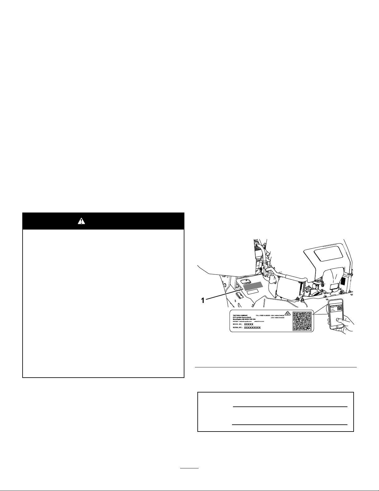
andserialnumbersofyourproductready.Figure1
identiesthelocationofthemodelandserialnumbers
ontheproduct.Writethenumbersinthespace
provided.
Important:Withyourmobiledevice,youcan
scantheQRcodeontheserialnumberdecal(if
equipped)toaccesswarranty,parts,andother
productinformation.
g234368
Figure1
1.Modelandserialnumberplate
©2019—TheToro®Company
8111LyndaleAvenueSouth
Bloomington,MN55420
Writetheproductmodelandserialnumbersinthe
spacebelow:
ModelNo.
SerialNo.
Thismanualuses2wordstohighlightinformation.
Importantcallsattentiontospecialmechanical
Contactusatwww.Toro.com.
2
AllRightsReserved
PrintedintheUSA

informationandNoteemphasizesgeneralinformation
worthyofspecialattention.
Contents
Safety.......................................................................4
SafetyAlertSymbol............................................4
GeneralSafety...................................................4
SlopeIndicator...................................................5
SafetyandInstructionalDecals..........................6
ProductOverview...................................................10
Controls............................................................11
Specications..................................................12
BeforeOperation.................................................12
BeforeOperationSafety...................................12
Pre-Start...........................................................13
FuelSafety.......................................................13
AddingFuel......................................................14
PerformingDailyMaintenance..........................15
BreakinginaNewMachine..............................15
UsingtheSafety-InterlockSystem....................15
PositioningtheSeat..........................................16
DuringOperation.................................................16
DuringOperationSafety...................................16
OperatingtheParkingBrake.............................18
OperatingtheMowerBlade-ControlSwitch
(PTO)............................................................19
OperatingtheThrottle.......................................19
OperatingtheChoke........................................20
OperatingtheKeySwitch.................................20
StartingtheEngine...........................................21
ShuttingOfftheEngine.....................................21
UsingtheMotion-ControlLevers.......................21
DrivingtheMachine..........................................22
UsingtheSideDischarge.................................23
AdjustingtheHeightofCut...............................23
AdjustingtheAnti-ScalpRollers........................24
OperatingTips.................................................24
AfterOperation....................................................25
AfterOperationSafety......................................25
PushingtheMachinebyHand..........................28
Maintenance...........................................................29
MaintenanceSafety..........................................29
RecommendedMaintenanceSchedule(s)...........30
EngineMaintenance...........................................31
EngineSafety...................................................31
ServicingtheAirCleaner..................................31
ServicingtheEngineOil....................................31
ServicingtheSparkPlug...................................34
CleaningtheCoolingSystem............................34
FuelSystemMaintenance...................................35
ReplacingtheIn-LineFuelFilter.......................35
ElectricalSystemMaintenance...........................36
ElectricalSystemSafety...................................36
ServicingtheBattery.........................................36
ServicingtheFuses..........................................38
DriveSystemMaintenance..................................38
CheckingtheTirePressure...............................38
BeltMaintenance................................................39
InspectingtheBelts..........................................39
ReplacingtheMowerBelt.................................39
MowerMaintenance.............................................40
BladeSafety.....................................................40
ServicingtheCuttingBlades.............................40
LevelingtheMowerDeck..................................43
RemovingtheMowerDeck...............................44
InstallingtheMowerDeck.................................45
ReplacingtheGrassDeector..........................46
Cleaning..............................................................47
DisposingofWaste...........................................47
Storage...................................................................47
StorageSafety..................................................47
CleaningandStorage.......................................47
StoringtheBattery............................................48
Troubleshooting......................................................49
Schematics.............................................................51
3

Safety
ThefollowinginstructionsarefromANSIstandard
B71.1-2017.
SafetyAlertSymbol
ThisSafetyAlertSymbol(Figure2)isusedbothin
thismanualandonthemachinetoidentifyimportant
safetymessageswhichmustbefollowedtoavoid
accidents.
Thissymbolmeans:ATTENTION!BECOMEALERT!
YOURSAFETYISINVOL VED!
Figure2
SafetyAlertSymbol
GeneralSafety
Thismachineiscapableofamputatinghandsandfeet
andofthrowingobjects.T orodesignedandtested
thislawnmowertoofferreasonablysafeservice;
however,failuretocomplywithsafetyinstructions
mayresultininjuryordeath.
•Read,understand,andfollowallinstructionsand
warningsintheOperator’sManualandother
trainingmaterial,onthemachine,engine,and
attachments.Alloperatorsandmechanicsshould
betrained.Iftheoperator(s)ormechanic(s)can
notreadthismanual,itistheowner’sresponsibility
toexplainthismaterialtothem;otherlanguages
maybeavailableonourwebsite.
•Onlyallowtrained,responsible,andphysically
capableoperatorsthatarefamiliarwiththesafe
g000502
operation,operatorcontrols,andsafetysignsand
instructionstooperatethemachine.Neverlet
childrenoruntrainedpeopleoperateorservicethe
equipment.Localregulationsmayrestricttheage
oftheoperator.
Thesafetyalertsymbolappearsaboveinformation
whichalertsyoutounsafeactionsorsituationsand
willbefollowedbythewordDANGER,WARNING,or
CAUTION.
DANGER:Indicatesanimminentlyhazardous
situationwhich,ifnotavoided,Willresultindeathor
seriousinjury.
WARNING:Indicatesapotentiallyhazardoussituation
which,ifnotavoided,Couldresultindeathorserious
injury.
CAUTION:Indicatesapotentiallyhazardoussituation
which,ifnotavoided,Mayresultinminorormoderate
injury.
Thismanualusestwootherwordstohighlight
information.Importantcallsattentiontospecial
mechanicalinformationandNoteemphasizesgeneral
informationworthyofspecialattention.
•DoNotoperatethemachineneardrop-offs,
ditches,embankments,water,orotherhazards,or
onslopesgreaterthan15degrees.
•DoNotputyourhandsorfeetnearmoving
componentsofthemachine.
•Neveroperatethemachinewithdamagedguards,
shields,orcovers.Alwayshavesafetyshields,
guards,switchesandotherdevicesinplaceandin
properworkingcondition.
•Stopthemachine,shutofftheengine,andremove
thekeybeforeservicing,fueling,orunclogging
themachine.
4

SlopeIndicator
Figure3
Youmaycopythispageforpersonaluse.
1.Themaximumslopeyoucanoperatethemachineonis15degrees.Usetheslopecharttodeterminethedegreeofslopeof
hillsbeforeoperating.Donotoperatethismachineonaslopegreaterthan15degrees.Foldalongtheappropriateline
tomatchtherecommendedslope.
2.Alignthisedgewithaverticalsurface,atree,building,fencepole,etc.
3.Exampleofhowtocompareslopewithfoldededge
5
g011841

SafetyandInstructionalDecals
Safetydecalsandinstructionsareeasilyvisibletotheoperatorandarelocatednearanyarea
ofpotentialdanger.Replaceanydecalthatisdamagedormissing.
Manufacturer'sMark
1.Indicatesthebladeisidentiedasapartfromtheoriginal
machinemanufacturer.
BatterySymbols
Someorallofthesesymbolsareonyourbattery .
1.Explosionhazard6.Keepbystandersaway
2.Nore,opename,or
smoking
3.Causticliquid/chemical
burnhazard
4.Weareyeprotection.9.Flusheyesimmediately
5.ReadtheOperator's
Manual.
fromthebattery .
7.Weareyeprotection;
explosivegasescan
causeblindnessandother
injuries.
8.Batteryacidcancause
blindnessorsevereburns.
withwaterandgetmedical
helpfast.
10.Containslead;donot
discard
decaloemmarkt
decal117-1 194
decalbatterysymbols
1.Beltrouting
2.Engine
117-1194
1.Bypassleverpositionfor
pushingthemachine
6
decal121-2989b
121-2989
2.Bypassleverpositionfor
operatingthemachine
decal130-0731
130-0731
1.Warning—thrownobject
hazard;keepthedeector
shieldinplace.
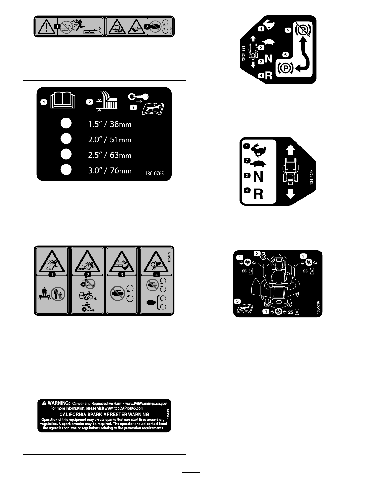
1.ReadtheOperator's
Manual.
2.Height-of-cutselection
2.Cuttinghazardofhandor
foot,mowerblade—keep
awayfrommovingparts.
130-0765
3.Removethekeyfromthe
keyswitchandreadthe
Operator'sManualbefore
performingmaintenance.
decal136-4243
136-4243
1.Fast4.Reverse
2.Slow
5.Parkingbrakedisengaged
3.Neutral6.Parkingbrakeengaged
decal130-0765
decal136-4244
136-4244
1.Fast3.Neutral
2.Slow
4.Reverse
1.Thrownobject
hazard—keepbystanders
awayfromthemachine.
2.Thrownobjecthazard,
raisedbafe—donot
operatethemachinewith
anopendeck;usea
baggerorabafe.
132-0872
3.Severinghazardofhand
4.Entanglement
133-8062
decal132-0872
orfoot—keepawayfrom
movingparts.
hazard—keepaway
frommovingparts;keep
allguardsandshieldsin
place.
decal133-8062
7
1.Checkthetirepressure
every25operatinghours.
2.Engineoil
3.Checkthetirepressure
every25operatinghours.
decal136-5596
136-5596
4.Checkthetirepressure
every25operatinghours.
5.ReadtheOperator's
Manualbeforeperforming
maintenance.
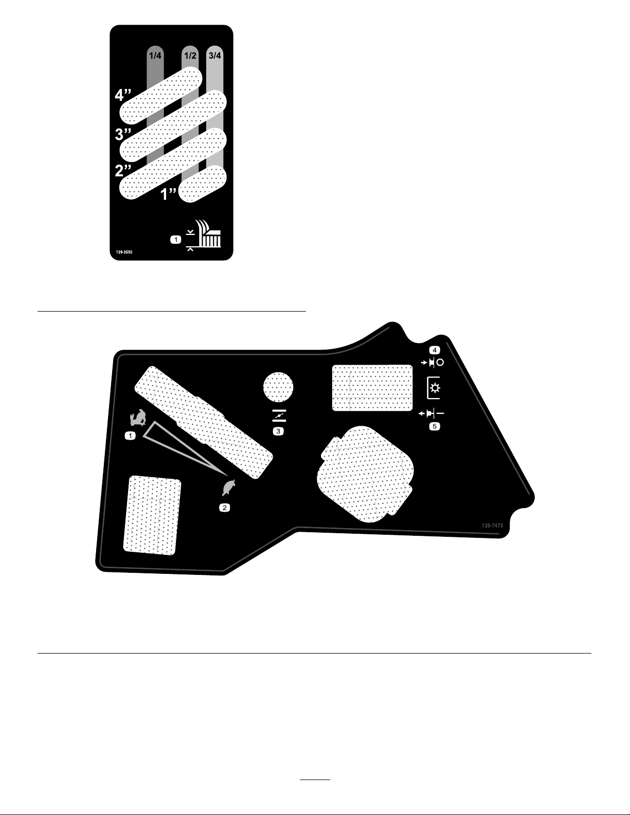
1.Heightofcut
decal139-3550
139-3550
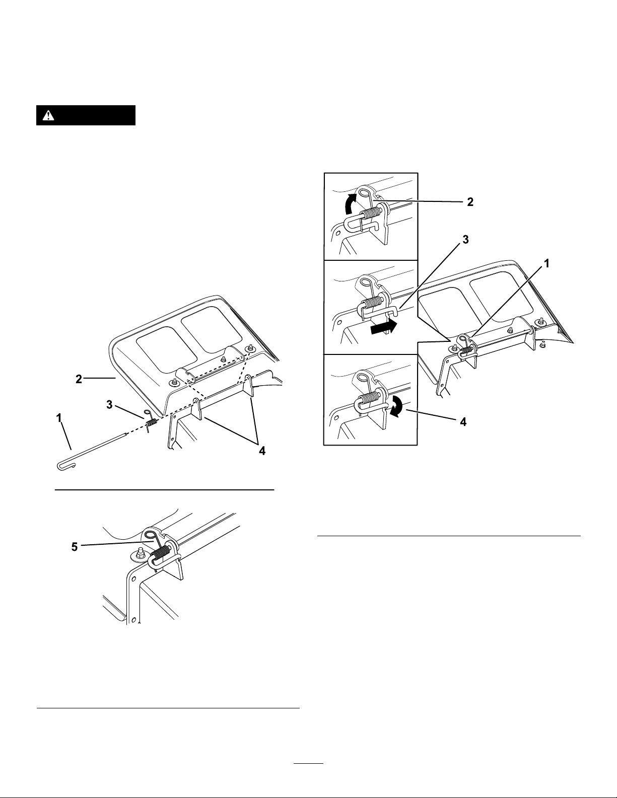
139-7473
1.Fast
2.Slow5.PTO—engage
3.Choke
decal139-7473
4.PTO—disengage
8

140-3451
Note:Thismachinecomplieswiththeindustrystandardstabilitytestinthestaticlateralandlongitudinaltestswiththemaximum
recommendedslopeindicatedonthedecal.ReviewtheinstructionsforoperatingthemachineonslopesintheOperator’sManualas
wellastheconditionsinwhichyouwouldoperatethemachinetodeterminewhetheryoucanoperatethemachineintheconditionson
thatdayandatthatsite.Changesintheterraincanresultinachangeinslopeoperationforthemachine.
decal140-3451
1.Warning—readtheOperator’sManual.5.Tippinghazard—donotusethemachineneardrop-offsoron
2.Warning—readtheOperator’sManualbeforeperforming
maintenance;movethetractioncontrolstotheParkposition,
removethekey,anddisconnectthesparkplugwire.
3.Runoverhazard—donotcarrypassengers;lookbehindyou
whenmovinginreverse.
4.Thrownobjecthazard—keepbystandersaway;pickupdebris
beforemowing;keepthedeectorinplace.
slopesgreaterthan15°;operateacrossslopeslessthan15°.
6.Cuttingdismembermenthazardofhand,mowerblade;
entanglementhazardofhand,belt—stayawayfrommoving
parts;keepallguardsandshieldsinplace.
7.Tippinghazard—donotusedualrampswhenloadingontoa
trailer;use1rampwideenoughforthemachine;usearamp
withaslopelessthan15°;backuptheramp(inreverse)and
driveforwardofftheramp.
9

ProductOverview
1.Deck-liftpedal4.Controls
2.Height-of-cutpin
3.Motion-controllever6.Fuelcap
5.Engine8.Anti-scalproller
g298660
Figure4
7.Mowerdeck10.Parking-brakelever
9.Casterwheel
10

Controls
ChokeControl
Becomefamiliarwithallthecontrolsbeforeyoustart
theengineandoperatethemachine.
ControlPanel
Figure5
1.Hourmeter4.Keyswitch
2.Throttlecontrol5.Blade-controlswitch
(powertakeoff)
3.Chokecontrol
Usethechokecontroltostartacoldengine(Figure5).
HourMeter
Thehourmeterrecordsthenumberofhoursthe
enginehasoperated.Itoperateswhentheengine
isrunning.Usethesetimesforschedulingregular
maintenance(Figure5).
Motion-ControlLevers
Usethemotion-controlleverstodrivethemachine
forward,reverse,andturneitherdirection(Figure4).
Neutral-LockPosition
g297595
Movethemotion-controlleversoutwardfromthe
centertotheNEUTRAL-LOCKpositionwhenexiting
themachine(Figure19).Alwayspositionthe
motion-controlleversintotheNEUTRAL-LOCKposition
whenyoustopthemachineorleaveitunattended.
FuelGauge
Thefuelgaugedisplaystheamountoffuelinthetank
(Figure6).
Figure6
Parking-BrakeLever
Theparking-brakeleverislocatedontheleftsideof
theconsole(Figure4).Thebrakeleverengagesa
parkingbrakeonthedrivewheels.
Toengagetheparkingbrake,pulluptheleveruntilit
latchesintothedetentslot.
Todisengagetheparkingbrake,pulltheleveroutof
thedetentslotandtowardyou,thenpushitdown.
FootPedalDeck-LiftSystem
Thefootpedaldeck-liftsystemallowsyoutolower
andraisethedeckfromtheseatedposition.Y ou
canusethefootpedaltoliftthedeckbrieytoavoid
obstacles(Figure4).
KeySwitch
Thekeyswitch,usedtostartandshutofftheengine,
g238298
has3positions:OFF,RUN,andSTART(Figure5).
RefertoStartingtheEngine(page21).
1.Fuelgauge2.Fuel-tankcap
ThrottleControl
Thethrottlecontrolstheenginespeed,andithasa
continuous-variablesettingfromtheSLOWtoFAST
position(Figure5).
Blade-ControlSwitch(Power
Takeoff)
Theblade-controlswitch,representedbya
power-takeoff(PTO)symbol,engagesand
disengagespowertothemowerblades(Figure5).
11

Height-of-CutPin
Theheight-of-cutpinworkswiththefootpedaltolock
thedeckinaspeciccuttingheight.Adjusttheheight
ofcutonlywhenthemachineisnotmoving(Figure4).
Operation
Note:Determinetheleftandrightsidesofthe
machinefromthenormaloperatingposition.
Attachments/Accessories
AselectionofT oroapprovedattachmentsand
accessoriesisavailableforusewiththemachine
toenhanceandexpanditscapabilities.Contact
yourAuthorizedServiceDealerorauthorizedT oro
distributororgotowww.Toro.comforalistofall
approvedattachmentsandaccessories.
Toensureoptimumperformanceandcontinuedsafety
certicationofthemachine,useonlygenuineT oro
replacementpartsandaccessories.Replacement
partsandaccessoriesmadebyothermanufacturers
couldbedangerous,andsuchusecouldvoidthe
productwarranty.
Specications
Specicationsanddesignaresubjecttochange
withoutnotice.
Cuttingwidth137cm(54inches)
Widthwithdeectordown178cm(70inches)
Widthwithdeectorraised155cm(61inches)
Length
Height
Weight
206cm(81inches)
122cm(48inches)
342kg(755lb)
BeforeOperation
BeforeOperationSafety
•Evaluatetheterraintodeterminewhataccessories
andattachmentsareneededtoproperlyand
safelyperformthejob.Onlyuseaccessoriesand
attachmentsapprovedbyToro.
•Inspecttheareawheretheequipmentistobe
usedandremoveallrocks,toys,sticks,wires,
bones,andotherforeignobjects.Thesecan
bethrownorinterferewiththeoperationofthe
machineandmaycausepersonalinjurytothe
operatororbystanders.
•Wearappropriatepersonalprotectiveequipment
suchassafetyglasses,substantialslip-resistant
footwear,andhearingprotection.Tiebacklong
hairandavoidlooseclothingandloosejewelry
whichmaygettangledinmovingparts.
CAUTION
Thismachineproducessoundlevelsin
excessof85dBAattheoperator’searand
cancausehearinglossthroughextended
periodsofexposure.
Wearhearingprotectionwhenoperating
thismachine.
•Checkthattheoperatorpresencecontrols,
safetyswitches,andshieldsareattachedand
functioningproperly.DoNotoperateunlessthey
arefunctioningproperly.
•DoNotoperatethemowerwhenpeople,especially
children,orpetsareinthearea.Stopthemachine
andattachment(s)ifanyoneentersthearea.
•DoNotoperatethemachinewithouttheentire
grasscollectionsystem,dischargedeector,
orothersafetydevicesinplaceandinproper
workingcondition.Grasscatchercomponents
aresubjecttowear,damageanddeterioration,
whichcouldexposemovingpartsorallowobjects
tobethrown.Frequentlycheckforwornor
deterioratingcomponentsandreplacethemwith
themanufacturer’srecommendedpartswhen
necessary.
12

Pre-Start
FuelSafety
Fillfueltankonlevelground.SeeFuel
RecommendationsintheSpecicationssectionfor
additionalgasolineinformation.
DoNotaddoiltogasoline.
DoNotoverllfueltank.Fillthefueltanktothebottom
ofthellerneck.Theemptyspaceinthetankallows
gasolinetoexpand.Overllingmayresultinfuel
leakageordamagetotheengineoremissionsystem.
Makesureyouunderstandthecontrols,theirlocations,
theirfunctions,andtheirsafetyrequirements.
RefertotheMaintenancesectionandperformallthe
necessaryinspectionandmaintenancesteps.
Useextremecarewhenhandlingfuel.
DANGER
Incertainconditionsgasolineisextremely
ammableandvaporsareexplosive.
Areorexplosionfromgasolinecanburn
you,others,andcausepropertydamage.
•Fillthefueltankoutdoorsonlevelground,
inanopenarea,whentheengineiscold.
Wipeupanygasolinethatspills.
•Neverrellthefueltankordrainthe
machineindoorsorinsideanenclosed
trailer.
•DoNotllthefueltankcompletelyfull.
Fillthefueltanktothebottomoftheller
neck.Theemptyspaceinthetankallows
gasolinetoexpand.Overllingmayresult
infuelleakageordamagetotheengineor
emissionsystem.
•Neversmokewhenhandlinggasoline,and
stayawayfromanopenameorwhere
gasolinefumesmaybeignitedbyspark.
•Storegasolineinanapprovedcontainer
andkeepitoutofthereachofchildren.
•Addfuelbeforestartingtheengine.Never
removethecapofthefueltankoraddfuel
whenengineisrunningorwhentheengine
ishot.
•Iffuelisspilled,DoNotattempttostart
theengine.Moveawayfromtheareaof
thespillandavoidcreatinganysourceof
ignitionuntilfuelvaporshavedissipated.
•DoNotoperatewithoutentireexhaust
systeminplaceandinproperworking
condition.
13

DANGER
Incertainconditionsduringfueling,static
electricitycanbereleasedcausingaspark
whichcanignitegasolinevapors.Areor
explosionfromgasolinecanburnyouand
othersandcausepropertydamage.
•Alwaysplacegasolinecontainersonthe
groundawayfromyourvehiclebefore
lling.
•DoNotllgasolinecontainersinsidea
vehicleoronatruckortrailerbedbecause
interiorcarpetsorplastictruckbedliners
mayinsulatethecontainerandslowthe
lossofanystaticcharge.
•Whenpractical,removegas-powered
equipmentfromthetruckortrailerand
refueltheequipmentwithitswheelsonthe
ground.
•Ifthisisnotpossible,thenrefuelsuch
equipmentonatruckortrailerfroma
portablecontainer,ratherthanfroma
gasolinedispensernozzle.
•Ifagasolinedispensernozzlemustbe
used,keepthenozzleincontactwiththe
rimofthefueltankorcontaineropeningat
alltimesuntilfuelingiscomplete.DoNot
useanozzlelockopendevice.
ameoranyenclosedareawhereopenpilotlights
orheatappliancesarepresent.
AddingFuel
RecommendedFuel
•Forbestresults,useonlyclean,fresh(lessthan
30daysold),unleadedgasolinewithanoctane
ratingof87orhigher((R+M)/2ratingmethod).
•Ethanol:Gasolinewithupto10%ethanol
(gasohol)or15%MTBE(methyltertiarybutyl
ether)byvolumeisacceptable.Ethanoland
MTBEarenotthesame.Gasolinewith15%
ethanol(E15)byvolumeisnotapprovedforuse.
Neverusegasolinethatcontainsmorethan
10%ethanolbyvolume,suchasE15(contains
15%ethanol),E20(contains20%ethanol),orE85
(containsupto85%ethanol).Usingunapproved
gasolinemaycauseperformanceproblemsand/or
enginedamagewhichmaynotbecoveredunder
warranty.
•Donotusegasolinecontainingmethanol.
•Donotstorefueleitherinthefueltankorfuel
containersoverthewinterunlessyouuseafuel
stabilizer.
•Donotaddoiltogasoline.
UsingStabilizer/Conditioner
WARNING
Gasolineisharmfulorfatalifswallowed.
Long-termexposuretovaporshascaused
cancerinlaboratoryanimals.Failuretouse
cautionmaycauseseriousinjuryorillness.
•Avoidprolongedbreathingofvapors.
•Keepfaceawayfromnozzleandgas
tank/containeropening.
•Keepawayfromeyesandskin.
•Neversiphonbymouth.
Tohelppreventres:
•Keepengineandengineareafreefrom
accumulationofgrass,leaves,excessivegrease
oroil,andotherdebriswhichcanaccumulatein
theseareas.
•Cleanupoilandfuelspillsandremovefuelsoaked
debris.
•Allowthemachinetocoolbeforestoringthe
machineinanyenclosure.DoNotstorenear
Usefuelstabilizer/conditionerinthemachineatall
timestokeepthefuelfreshlongerwhenusedas
directedbythefuel-stabilizermanufacturer.
Important:Donotusefueladditivescontaining
methanolorethanol.
Addtheamountoffuelstabilizer/conditionertofresh
fuelasdirectedbythefuel-stabilizermanufacturer.
FillingtheFuelTank
1.Parkthemachineonalevelsurface.
2.Engagetheparkingbrake.
3.Shutofftheengineandremovethekey.
4.Cleanaroundthefuel-tankcap.
5.Fillthefueltankuntilthefuelgaugereadsatthe
fullmark(Figure7).
Note:Donotllthefueltankcompletelyfull.
Theemptyspaceinthetankallowsthefuelto
expand.
14

Figure7
UsingtheSafety-Interlock
System
WARNING
Ifthesafety-interlockswitchesare
disconnectedordamaged,themachinecould
operateunexpectedly,causingpersonal
injury.
•Donottamperwiththeinterlockswitches.
•Checktheoperationoftheinterlock
switchesdailyandreplaceanydamaged
switchesbeforeoperatingthemachine.
Understandingthe
Safety-InterlockSystem
Thesafety-interlocksystemisdesignedtopreventthe
enginefromstartingunless:
•Theblade-controlswitch(PTO)isdisengaged.
•Themotion-controlleversareintheNEUTRAL-LOCK
g197123
position.
•Theparkingbrakeisengaged.
PerformingDaily
Maintenance
Beforestartingthemachineeachday ,performthe
EachUse/DailyprocedureslistedinMaintenance
(page29).
BreakinginaNewMachine
Newenginestaketimetodevelopfullpower.Mower
decksanddrivesystemshavehigherfrictionwhen
new,placingadditionalloadontheengine.Allow
40to50hoursofbreak-intimefornewmachinesto
developfullpowerandbestperformance.
Thesafety-interlocksystemalsoisdesignedtoshut
offtheenginewheneverthecontrolleversareoutof
theNEUTRAL-LOCKpositionandyourisefromtheseat.
TestingtheSafety-Interlock
System
ServiceInterval:Beforeeachuseordaily
Testthesafety-interlocksystembeforeyouusethe
machineeachtime.Ifthesafetysystemdoesnot
operateasdescribedbelow,haveanAuthorized
ServiceDealerrepairthesafetysystemimmediately .
1.Sitontheseat,engagetheparkingbrake,and
movetheblade-controlswitch(PTO)totheON
position.Trystartingtheengine;theengine
shouldnotcrank.
2.Sitontheseat,engagetheparkingbrake,and
movetheblade-controlswitch(PTO)totheOFF
position.Moveeithermotion-controllever(out
oftheNEUTRAL-LOCKposition).Trystartingthe
engine;theengineshouldnotcrank.Repeatfor
othercontrollever.
3.Sitontheseat,engagetheparkingbrake,
movetheblade-controlswitch(PTO)totheOFF
position,andmovethemotion-controlleversto
theNEUTRAL-LOCKposition.Starttheengine.
Whiletheengineisrunning,releasetheparking
brake,engagetheblade-controlswitch(PTO),
andriseslightlyfromtheseat;theengineshould
shutoff.
15

4.Sitontheseat,engagetheparkingbrake,
movetheblade-controlswitch(PTO)totheOFF
position,andmovethemotion-controllevers
toNEUTRAL-LOCKposition.Starttheengine.
Whiletheengineisrunning,centereither
motion-controlleverandmoveitforwardor
reverse;theengineshouldshutoff.Repeatfor
othermotion-controllever.
5.Sitontheseat,disengagetheparkingbrake,
movetheblade-controlswitch(PTO)totheOFF
position,andmovethemotion-controlleversto
NEUTRAL-LOCKposition.Trystartingtheengine;
theengineshouldnotcrank.
PositioningtheSeat
Theseatcanmoveforwardandbackward.Position
theseatwhereyouhavethebestcontrolofthe
machineandaremostcomfortable(Figure8).
DuringOperation
DuringOperationSafety
GeneralSafety
Theoperatormustusetheirfullattentionwhen
operatingthemachine.DoNotengageinanyactivity
thatcausesdistractions;otherwise,injuryorproperty
damagemayoccur.
WARNING
Operatingengineparts,especiallythemufer,
becomeextremelyhot.Severeburnscan
occuroncontactanddebris,suchasleaves,
grass,brush,etc.cancatchre.
•Allowengineparts,especiallythemufer,
tocoolbeforetouching.
•Removeaccumulateddebrisfrommufer
andenginearea.
Figure8
WARNING
Engineexhaustcontainscarbonmonoxide,
whichisanodorlessdeadlypoisonthatcan
killyou.
DoNotrunengineindoorsorinasmall
connedareawheredangerouscarbon
monoxidefumescancollect.
•Theowner/usercanpreventandisresponsible
foraccidentsorinjuriesoccurringtohimselfor
g027632
herself,otherpeopleorproperty .
•Thismowerwasdesignedforoneoperatoronly .
Donotcarrypassengersandkeepallothersaway
frommachineduringoperation.
•DoNotoperatethemachineundertheinuence
ofalcoholordrugs.
•Operateonlyindaylightorgoodarticiallight.
•Lightningcancausesevereinjuryordeath.If
lightningisseenorthunderisheardinthearea,
DoNotoperatethemachine;seekshelter.
•Useextracarewhileoperatingwithaccessoriesor
attachments,suchasgrasscollectionsystems.
Thesecanchangethestabilityofthemachine
andcausealossofcontrol.Followdirectionsfor
counterweightsifrequired.
•Keepawayfromholes,ruts,bumps,rocks,and
otherhiddenhazards.Usecarewhenapproaching
blindcorners,shrubs,trees,tallgrassorother
objectsthatmayhideobstaclesorobscurevision.
Uneventerraincouldoverturnthemachineor
causetheoperatortolosetheirbalanceorfooting.
16

•Besurealldrivesareinneutralandparkingbrake
isengagedbeforestartingengine.
•Starttheenginecarefullyaccordingtoinstructions
withfeetwellawayfromtheblades.
•Neveroperatethemowerwithdamagedguards,
shields,orcovers.Alwayshavesafetyshields,
guards,switchesandotherdevicesinplaceandin
properworkingcondition.
•Keepclearofthedischargeopeningatalltimes.
Nevermowwiththedischargedoorraised,
removedoralteredunlessthereisagrass
collectionsystemormulchkitinplaceandworking
properly.
•Keephandsandfeetawayfrommovingparts.
Ifpossible,DoNotmakeadjustmentswiththe
enginerunning.
WARNING
Hands,feet,hair,clothing,oraccessories
canbecomeentangledinrotatingparts.
Contactwiththerotatingpartscan
causetraumaticamputationorsevere
lacerations.
–DoNotoperatethemachinewithout
guards,shields,andsafetydevicesin
placeandworkingproperly.
–Keephands,feet,hair,jewelry,or
clothingawayfromrotatingparts.
–Wheneveryouleavethemower.DoNotleave
arunningmachineunattended.
•Stopengine,waitforallmovingpartstostop:
–Beforerefueling.
–Beforedumpingthegrasscatcher.
–Beforemakingheightadjustments.
•Tragicaccidentscanoccuriftheoperatorisnot
alerttothepresenceofchildren.Childrenare
oftenattractedtothemachineandthemowing
activity.Neverassumethatchildrenwillremain
whereyoulastsawthem.
–Keepchildrenoutofthemowingareaand
underthewatchfulcareofanotherresponsible
adult,nottheoperator.
–Bealertandturnthemachineoffifchildren
enterthearea.
–Beforeandwhilebackingorchangingdirection,
lookbehind,down,andside-to-sideforsmall
children.
–Neverallowchildrentooperatethemachine.
–DoNotcarrychildren,evenwiththeblades
shutoff.Childrencouldfalloffandbeseriously
injuredorinterferewiththesafeoperationof
themachine.Childrenthathavebeengiven
ridesinthepastcouldsuddenlyappearinthe
workingareaforanotherrideandberunover
orbackedoverbythemachine.
•Neverraisethedeckwithbladesrunning.
•Beawareofthemowerdischargepathanddirect
dischargeawayfromothers.Avoiddischarging
materialagainstawallorobstructionasthe
materialmayricochetbacktowardtheoperator.
Stoptheblades,slowdown,andusecautionwhen
crossingsurfacesotherthangrassandwhen
transportingthemowertoandfromtheareatobe
mowed.
•Bealert,slowdownandusecautionwhen
makingturns.Lookbehindandtothesidebefore
changingdirections.DoNotmowinreverse
unlessabsolutelynecessary.
•DoNotchangetheenginegovernorsettingor
overspeedtheengine.
•Parkthemachineonlevelground.Stopengine,
waitforallmovingpartstostop,andremovethe
sparkplugwire(s).
–Beforechecking,cleaningorworkingonthe
mower.
–Afterstrikingaforeignobjectorabnormal
vibrationoccurs(inspectthemowerfor
damageandmakerepairsbeforerestarting
andoperatingthemower).
–Beforeclearingblockages.
SlopeSafety
•Slopesareamajorfactorrelatedtolossofcontrol
androlloveraccidents,whichcanresultinsevere
injuryordeath.Theoperatorisresponsiblefor
safeslopeoperation.Operatingthemachineon
anysloperequiresextracaution.Beforeusingthe
machineonaslope,theoperatormust:
–Reviewandunderstandtheslopeinstructions
inthemanualandonthemachine.
–Useanangleindicatortodeterminethe
approximateslopeangleofthearea.
–Neveroperateonslopesgreaterthan15
degrees.
–Evaluatethesiteconditionsofthedayto
determineiftheslopeissafeformachine
operation.Usecommonsenseandgood
judgmentwhenperformingthisevaluation.
Changesintheterrain,suchasmoisture,can
quicklyaffecttheoperationofthemachineon
aslope.
•Identifyhazardsatthebaseoftheslope.Do
Notoperatethemachineneardropoffs,ditches,
embankments,waterorotherhazards.The
machinecouldsuddenlyrolloverifawheelgoes
overtheedgeortheedgecollapses.Keepasafe
17

distance(twicethewidthofthemachine)between
themachineandanyhazard.Useawalkbehind
machineorahandtrimmertomowthegrassin
theseareas.
Figure9
1.SafeZone-Usethemowerhereonslopeslessthan15
degrees
2.DangerZone-Useawalk-behindmowerand/orhand
trimmeronslopesgreaterthan15degrees
3.Water
4.W=widthofthemachine
5.Keepasafedistance(twicethewidthofthemachine)
betweenthemachineandanyhazard.
g22911 1
TowingSafety
•Donotattachtowedequipmentexceptatthehitch
point.
•Donotusethemachineasatowingvehicleunless
ithasahitchinstalled.
•Donotexceedtheweightlimitsfortowed
equipmentandtowingonslopes.Thetowed
weightmustnotexceedtheweightofthemachine
andoperator.
•Neverallowchildrenorothersnearthetowed
equipment.
•Onslopes,theweightofthetowedequipmentmay
causelossoftraction,increasedriskofrollover,
andlossofcontrol.Reducethetowedweightand
slowdown.
•Thestoppingdistancemayincreasewiththe
weightofatowedload.Travelslowlyandallow
extradistancetostop.
•Makewideturnstokeeptheattachmentclearof
themachine.
OperatingtheParking
Brake
Alwaysengagetheparkingbrakewhenyoustopthe
machineorleaveitunattended.
•Avoidstarting,stoppingorturningthemachineon
slopes.Avoidmakingsuddenchangesinspeedor
direction;turnslowlyandgradually.
•DoNotoperateamachineunderanyconditions
wheretraction,steeringorstabilityisinquestion.
Beawarethatoperatingthemachineonwet
grass,acrossslopesordownhillmaycausethe
machinetolosetraction.Lossoftractiontothe
drivewheelsmayresultinslidingandalossof
brakingandsteering.Themachinecanslideeven
ifthedrivewheelsarestopped.
•Removeormarkobstaclessuchasditches,holes,
ruts,bumps,rocksorotherhiddenhazards.T all
grasscanhideobstacles.Uneventerraincould
overturnthemachine.
•Useextracarewhileoperatingwithaccessoriesor
attachments,suchasgrasscollectionsystems.
Thesecanchangethestabilityofthemachine
andcausealossofcontrol.Followdirectionsfor
counterweights.
•Ifpossible,keepthedeckloweredtotheground
whileoperatingonslopes.Raisingthedeckwhile
operatingonslopescancausethemachineto
becomeunstable.
EngagingtheParkingBrake
Parkthemachineonalevelsurface.
g188778
Figure10
18

DisengagingtheParkingBrake
Todisengagetheparkingbrake,pulltheleveroutof
thedetentslotandtowardyou,thenpushitdown
(Figure11).
Figure11
1.Pushtheparkingbrake
outofthedetentslotand
towardyou.
2.Pushtheparkingbrake
down.
g295538
Figure13
g188777
DisengagingtheBlade-Control
Switch(PTO)
OperatingtheMower
Blade-ControlSwitch(PTO)
Theblade-controlswitch(PTO)startsandstopsthe
mowerbladesandanypoweredattachments.
EngagingtheBlade-Control
Switch(PTO)
Figure12
Note:Alwaysengagethebladeswiththethrottlein
theFASTposition(Figure13).
g009174
Figure14
OperatingtheThrottle
YoucanmovethethrottlecontrolbetweentheFAST
andSLOWpositions(Figure15).
AlwaysusetheFASTpositionwhenengagingthePTO.
g008945
g295539
Figure15
19

OperatingtheChoke
OperatingtheKeySwitch
Usethechoketostartacoldengine.
1.Pullupthechokeknobtoengagethechoke
beforeusingthekeyswitch(Figure16).
2.Pushdownthechokeknobtodisengagethe
chokeaftertheenginehasstarted(Figure16).
1.TurnthekeytotheSTARTposition(Figure17).
Note:Whentheenginestarts,releasethekey.
Important:Donotengagethestartermotor
formorethan5secondsatatime.Ifthe
enginefailstostart,wait10secondsbetween
attempts.Failuretofollowtheseinstructions
canburnoutthestartermotor.
Note:Y oumayneedmultipleattemptstostart
theenginewhenyoustartitthersttimeafter
thefuelsystemhasbeenwithoutfuelcompletely.
g008947
Figure17
Figure16
1.ONposition2.OFFposition
g295540
2.TurnthekeytotheSTOPpositiontoshutoffthe
engine.
20

StartingtheEngine
CAUTION
Note:Awarmorhotenginemaynotrequirechoking.
Important:Donotengagethestarterformore
than5secondsatatime.Engagingthestarter
motorformorethan5secondscandamagethe
startermotor.Iftheenginefailstostart,wait10
secondsbeforeoperatingtheenginestarteragain.
Childrenorbystandersmaybeinjuredifthey
moveorattempttooperatethemachinewhile
itisunattended.
Alwaysremovethekeyandengagethe
parkingbrakewhenleavingthemachine
unattended.
UsingtheMotion-Control
Levers
Figure18
ShuttingOfftheEngine
1.Disengagethebladesbymovingthe
blade-controlswitchtotheOFFposition(Figure
14).
2.Engagetheparkingbrake;refertoEngagingthe
ParkingBrake(page18).
3.MovethethrottlelevertotheSLOWpositionand
lettheengineidlefor1minute.
4.TurnthekeytotheOFFpositionandremove
thekey.
g004532
g297307
1.Motion-control
lever—NEUTRAL-LOCK
position
2.Center,unlockedposition5.Frontofmachine
3.Forward
21
Figure19
4.Backward

DrivingtheMachine
Thedrivewheelsturnindependently,poweredby
hydraulicmotorsoneachaxle.Youcanturn1side
inreversewhileyouturntheotherforward,causing
themachinetospinratherthanturn.Thisgreatly
improvesthemachinemaneuverabilitybutmay
requiresometimeforyoutoadapttohowitmoves.
Thethrottlecontrolregulatestheenginespeedas
measuredinrpm(revolutionsperminute).Place
thethrottlecontrolintheFASTpositionforbest
performance.Alwaysoperateinthefullthrottle
positionwhenmowing.
WARNING
Themachinecanspinveryrapidly.Y ou
maylosecontrolofthemachineandcause
personalinjuryordamagetothemachine.
•Usecautionwhenmakingturns.
•Slowthemachinedownbeforemaking
sharpturns.
DrivingForward
Note:Theengineshutsoffwhenyoumovethe
traction-controlwiththeparkingbrakeengaged.
Tostopthemachine,pullthemotion-controllevers
totheNEUTRALposition.
1.Disengagetheparkingbrake;referto
DisengagingtheParkingBrake(page19).
2.Movetheleverstothecenter,unlockedposition.
3.Togoforward,slowlypushthemotion-control
leversforward(Figure20).
g008952
Figure20
DrivingBackward
1.Movetheleverstothecenter,unlockedposition.
2.Togobackward,slowlypullthemotion-control
leversrearward(Figure21).
g008953
Figure21
22

UsingtheSideDischarge
AdjustingtheHeightofCut
Themowerhasahingedgrassdeectorthat
dispersesclippingstothesideanddowntowardthe
turf.
DANGER
Withoutagrassdeector,dischargecover,or
acompletegrass-catcherassemblymounted
inplace,youandothersareexposedtoblade
contactandthrowndebris.Contactwith
rotatingmowerblade(s)andthrowndebris
willcauseinjuryordeath.
•Neverremovethegrassdeectorfromthe
mowerdeckbecausethegrassdeector
routesmaterialdowntowardtheturf.Ifthe
grassdeectoriseverdamaged,replaceit
immediately.
•Neverputyourhandsorfeetunderthe
mowerdeck.
•Nevertrytoclearthedischargearea
ormowerbladesunlessyoumovethe
blade-controlswitch(PTO)totheOFF
position,rotatethekeyswitchtotheOFF
position,andremovethekeyfromthekey
switch.
Themachineisequippedwithafootpedaldeck-lift
system.Youcanusethefootpedaltoliftthedeck
brieytoavoidobstaclesandtoraisethedeck.
Youcanadjusttheheightofcutfrom38to114mm
(1-1/2to4-1/2inches)in6mm(1/4inch)increments
bymovingtheheight-of-cutpinintodifferenthole
locations.
1.Pushonthedeck-liftpedalwithyourfoottoraise
themowerdeck.
2.Toadjust,removethepinfromtheheight-of-cut
bracket(Figure22).
3.Selectaholeintheheight-of-cutsystem
correspondingtothedesiredheightofcutand
insertthepin(Figure22).
4.Lowerthedeckslowlyuntilthelevermakes
contactwiththepin.
•Makesurethatthegrassdeectorisinthe
downposition.
1.Deck-liftpedal
2.Height-of-cutpositions
g297360
Figure22
3.Pin
23

AdjustingtheAnti-Scalp
OperatingTips
Rollers
Wheneveryouchangetheheightofcut,adjustthe
heightoftheanti-scalprollers.
Note:Adjusttheanti-scalprollerssothattherollers
donottouchthegroundinnormal,atmowingareas.
1.Parkthemachineonalevelsurface,disengage
theblade-controlswitchandengagetheparking
brake;refertoEngagingtheParkingBrake
(page18).
2.Shutofftheengine,removethekey ,andwait
forallmovingpartstostopbeforeleavingthe
operatingposition.
3.Adjusttheanti-scalprollersasshowninFigure
23.
UsingtheFastThrottleSetting
Forbestmowingandmaximumaircirculation,operate
theengineattheFASTposition.Airisrequiredto
thoroughlycutgrassclippings,sodonotsetthe
height-of-cutsolowastototallysurroundthemower
deckinuncutgrass.Alwaystrytohave1sideofthe
mowerdeckfreefromuncutgrass,whichallowsair
tobedrawnintothemowerdeck.
CuttingaLawnfortheFirstTime
Cutgrassslightlylongerthannormaltoensurethat
thecuttingheightofthemowerdeckdoesnotscalp
anyunevenground.However,thecuttingheight
usedinthepastisgenerallythebestonetouse.
Whencuttinggrasslongerthan15cm(6inches)tall,
youmaywanttocutthelawntwicetoensurean
acceptablequalityofcut.
CuttingaThirdoftheGrassBlade
Itisbesttocutonlyaboutathirdofthegrassblade.
Cuttingmorethanthatisnotrecommendedunless
grassissparse,oritislatefallwhengrassgrows
moreslowly.
Figure23
1.Anti-scalproller4.Flangenut
2.Spacer
3.Bushing
5.Bolt
AlternatingtheMowingDirection
g029955
Alternatethemowingdirectiontokeepthegrass
standingstraight.Thisalsohelpsdisperseclippings,
whichenhancesdecompositionandfertilization.
MowingatCorrectIntervals
Grassgrowsatdifferentratesatdifferenttimesof
theyear.Tomaintainthesamecuttingheight,mow
moreofteninearlyspring.Asthegrassgrowthrate
slowsinmidsummer,mowlessfrequently.Ifyou
cannotmowforanextendedperiod,rstmowata
highcuttingheight,thenmowagain2dayslaterata
lowerheightsetting.
UsingaSlowerCuttingSpeed
Toimprovecutquality,useaslowergroundspeed
incertainconditions.
AvoidingCuttingTooLow
Whenmowinguneventurf,raisethecuttingheight
toavoidscalpingtheturf.
StoppingtheMachine
Ifyoumuststoptheforwardmotionofthemachine
whilemowing,aclumpofgrassclippingsmay
24

dropontoyourlawn.Toavoidthis,moveontoa
previouslycutareawiththebladesengagedoryou
candisengagethemowerdeckwhilemovingforward.
KeepingtheUndersideofthe
MowerDeckClean
Cleanclippingsanddirtfromtheundersideofthe
mowerdeckaftereachuse.Ifgrassanddirtbuildup
insidethemowerdeck,cuttingqualitywilleventually
becomeunsatisfactory.
MaintainingtheBlade(s)
Maintainasharpbladethroughoutthecuttingseason
becauseasharpbladecutscleanlywithouttearingor
shreddingthegrassblades.Tearingandshredding
turnsgrassbrownattheedges,whichslowsgrowth
andincreasesthechanceofdisease.Checkthe
mowerbladesaftereachuseforsharpness,and
foranywearordamage.Filedownanynicksand
sharpenthebladesasnecessary .Ifabladeis
damagedorworn,replaceitimmediatelywitha
genuineT ororeplacementblade.
AfterOperation
AfterOperationSafety
GeneralSafety
•Parkmachineonlevelground,disengagedrives,
setparkingbrake,stopengine,removekeyor
disconnectsparkplugwire.Waitforallmovement
tostopandallowthemachinetocoolbefore
adjusting,cleaning,repairing,orstoring.Never
allowuntrainedpersonneltoservicemachine.
•CleanthemachineasstatedintheMaintenance
section.Keepengineandengineareafreefrom
accumulationofgrass,leaves,excessivegrease
oroil,andotherdebriswhichcanaccumulate
intheseareas.Thesematerialscanbecome
combustibleandmayresultinare.
•Frequentlycheckforwornordeteriorating
componentsthatcouldcreateahazard.Tighten
loosehardware.
Transporting
TransportingtheMachine
Useaheavy-dutytrailerortrucktotransportthe
machine.Ensurethatthetrailerortruckhasall
necessarylightingandmarkingasrequiredbylaw.
Thoroughlyreadallofthesafetyinstructions.Knowing
thisinformationcouldhelpyou,yourfamily,pets,or
bystandersavoidinjury.
Totransportthemachine:
•Lockthebrakeandblockthewheels.
•Securelyfastenthemachinetothetrailerortruck
withstraps,chains,cable,orropes.Onlyusethe
designatedtie-downlocationsonthemoweras
showninFigure24.Usetheselocationseven
whentransportingthemowerwithanattached
accessory.Usingnon-designatedlocationsmay
causedamagetothemowerand/orattachment.
Figure24
•Secureatrailertothetowingvehiclewithsafety
chains.
25
g027708

WARNING
WARNING
Drivingonthestreetorroadwaywithout
turnsignals,lights,reectivemarkings,
oraslowmovingvehicleemblemis
dangerousandcanleadtoaccidents
causingpersonalinjury.
Donotdrivemachineonapublicstreetor
roadway.
LoadingtheMachine
Useextremecautionwhenloadingorunloading
machinesontoatraileroratruck.Useafull-width
rampthatiswiderthanthemachineforthisprocedure.
Backuprampsanddriveforwarddownramps(Figure
25).
Figure25
1.Backupramps
2.Driveforwarddownramps
Loadingamachineontoatrailerortruck
increasesthepossibilityoftip-overandcould
causeseriousinjuryordeath.
•Useextremecautionwhenoperatinga
machineonaramp.
•Useonlyafull-widthramp;donotuse
individualrampsforeachsideofthe
machine.
•Donotexceeda15-degreeanglebetween
therampandthegroundorbetweenthe
rampandthetrailerortruck.
•Ensurethelengthoframpisatleastfour
times(4X)aslongastheheightofthe
trailerortruckbedtotheground.Thiswill
ensurethatrampangledoesnotexceed15
degreesonatground.
•Backuprampsanddriveforwarddown
ramps.
•Avoidsuddenaccelerationordeceleration
g027995
whiledrivingthemachineonarampas
thiscouldcausealossofcontrolora
tip-oversituation.
Important:Donotusenarrowindividualramps
foreachsideofthemachine.
Ensuretherampislongenoughsothattheanglewith
thegrounddoesnotexceed15degrees(Figure25).
Onatground,thisrequiresaramptobeatleastfour
times(4X)aslongastheheightofthetrailerortruck
bedtotheground.Asteeperanglemaycausemower
componentstogetcaughtastheunitmovesfromthe
ramptothetrailerortruck.Steeperanglesmayalso
causethemachinetotiporlosecontrol.Ifloadingon
ornearaslope,positionthetrailerortrucksothatitis
onthedownsideoftheslopeandtherampextends
uptheslope.Thiswillminimizetherampangle.
26

Figure26
g027996
1.Full-widthrampinstowed
position
2.Sideviewoffull-width
rampinloadingposition
3.Notgreaterthan
15degrees
4.Rampisatleastfourtimes
(4X)aslongastheheight
ofthetrailerortruckbed
totheground
5.H=heightofthetraileror
truckbedtotheground
6.Trailer
27

PushingtheMachineby
Hand
Important:Alwayspushthemachinebyhand.
Donottowthemachine,becausetowingmay
damageit.
PushingtheMachine
1.Parkthemachineonalevelsurface,disengage
theblade-controlswitch,andengagetheparking
brake.
2.Shutofftheengine,removethekey ,andwait
forallmovingpartstostopbeforeleavingthe
operatingposition.
3.Locatethebypassleversontheframeonboth
sidesoftheengine.
4.Movethebypassleversforwardthroughthekey
holeanddowntolocktheminplace(Figure27).
Note:Dothisforeachlever.
5.Disengagetheparkingbrake.
g298692
Figure27
1.Bypass-leverlocations
2.Leverpositionfor
operatingthemachine
6.Whennished,engagetheparkingbrake.
3.Leverpositionforpushing
themachine
OperatingtheMachine
Movethebypassleversrearwardthroughthekeyhole
anddowntolocktheminplaceasshowninFigure27.
Note:Dothisforeachlever.
28

Maintenance
Note:Determinetheleftandrightsidesofthe
machinefromthenormaloperatingposition.
MaintenanceSafety
WARNING
Whilemaintenanceoradjustmentsarebeing
made,someonecouldstarttheengine.
Accidentalstartingoftheenginecould
seriouslyinjureyouorotherbystanders.
WARNING
Removalormodicationoforiginal
equipment,partsand/oraccessories
mayalterthewarranty ,controllability,
andsafetyofthemachine.Unauthorized
modicationstotheoriginalequipmentor
failuretouseoriginalToropartscouldlead
toseriousinjuryordeath.Unauthorized
changestothemachine,engine,fuelor
ventingsystem,mayviolateapplicable
safetystandardssuchas:ANSI,OSHAand
NFPAand/orgovernmentregulationssuch
asEP AandCARB.
Removethekeyfromtheignitionswitch,
engageparkingbrake,andpullthewire(s)
offthesparkplug(s)beforeyoudoany
maintenance.Alsopushthewire(s)asideso
itdoesnotaccidentallycontactthespark
plug(s).
WARNING
Theenginecanbecomeveryhot.Touchinga
hotenginecancausesevereburns.
Allowtheenginetocoolcompletelybefore
serviceormakingrepairsaroundtheengine
area.
•Parkmachineonlevelground,disengagedrives,
setparkingbrake,stopengine,removekeyor
disconnectsparkplugwire.Waitforallmovement
tostopandallowthemachinetocoolbefore
adjusting,cleaningorrepairing.Neverallow
untrainedpersonneltoservicemachine.
•Disconnectbatteryorremovesparkplugwire
beforemakinganyrepairs.Disconnectthe
negativeterminalrstandthepositivelast.
Reconnectpositiverstandnegativelast.
•Keepthemachine,guards,shieldsandall
safetydevicesinplaceandinsafeworking
condition.Frequentlycheckforwornor
deterioratingcomponentsandreplacethemwith
themanufacturer’srecommendedpartswhen
necessary.
•Usecarewhencheckingblades.Wrapthe
blade(s)orweargloves,andusecautionwhen
servicingthem.Onlyreplacedamagedblades.
Neverstraightenorweldthem.
•Usejackstandstosupportthemachineand/or
componentswhenrequired.
CAUTION
Raisingthemachineforserviceor
maintenancerelyingsolelyonmechanical
orhydraulicjackscouldbedangerous.
Themechanicalorhydraulicjacksmaynot
beenoughsupportormaymalfunction
allowingthemachinetofall,whichcould
causeinjury.
Donotrelysolelyonmechanicalor
hydraulicjacksforsupport.Useadequate
jackstandsorequivalentsupport.
•Carefullyreleasepressurefromcomponentswith
storedenergy.
•Keephandsandfeetawayfrommovingparts.
Ifpossible,DoNotmakeadjustmentswiththe
enginerunning.Ifthemaintenanceoradjustment
procedurerequiretheenginetoberunningand
componentsmoving,useextremecaution.
WARNING
Contactwithmovingpartsorhotsurfaces
maycausepersonalinjury .
Keepyourngers,hands,andclothing
clearofrotatingcomponentsandhot
surfaces.
•Checkallboltsfrequentlytomaintainproper
tightness.
29

RecommendedMaintenanceSchedule(s)
MaintenanceService
Interval
Aftertherst8hours
Beforeeachuseordaily
Every25hours
Every100hours
Every200hours
Every300hours
Beforestorage
MaintenanceProcedure
•Changetheengineoil.
•Checkthesafety-interlocksystem.
•Cleanandchecktheair-cleanerelement.
•Checktheengine-oillevel.
•Cleantheengineairintakescreen.
•Inspecttheblades.
•Inspectthegrassdeectorfordamage.
•Checktirepressure.
•Checkthebeltsforwearorcracks.
•Cleanthepaperair-cleanerelement(moreoftenindirtyordustyconditions).
•Changetheengineoil(moreoftenindirtyordustyconditions).
•Replaceorcleanandgapthesparkplug.
•Checkandcleanthecoolingnsandinsidetheengineshrouds.
•Replacethein-linefuellter.
•Replacethepaperair-cleanerelement(moreoftenindirtyordustyconditions).
•Changetheengine-oillter(moreoftenindirtyordustyconditions).
•Checkandadjustthevalveclearance.ContactanAuthorizedServiceDealer.
•Chargethebatteryanddisconnectthebatterycables.
•Performallmaintenanceprocedureslistedabovebeforestorage.
•Paintanychippedsurfaces.
Important:Refertoyourengineowner'smanualforadditionalmaintenanceprocedures.
CAUTION
Ifyouleavethekeyintheswitch,someonecouldaccidentlystarttheengineandseriously
injureyouorotherbystanders.
Shutofftheengineandremovethekeyfromtheswitchbeforeyouperformanymaintenance.
30

EngineMaintenance
ServicingthePaperAir-Cleaner
Element
EngineSafety
•Shutofftheenginebeforecheckingtheoilor
addingoiltothecrankcase.
•Keepyourhands,feet,face,clothing,andother
bodypartsawaythemuferandotherhotsurfaces.
ServicingtheAirCleaner
ServiceInterval:Beforeeachuseordaily—Clean
andchecktheair-cleanerelement.
Note:Servicetheaircleanermorefrequently(every
fewhours)ifoperatingconditionsareextremelydusty
orsandy.
RemovingtheAir-CleanerPaper
Element
1.Parkthemachineonalevelsurface,disengage
theblade-controlswitch(PTO),andengagethe
parkingbrake.
2.Shutofftheengine,removethekey ,andwait
forallmovingpartstostopbeforeleavingthe
operatingposition.
3.Cleanaroundtheair-cleanercovertoprevent
dirtfromgettingintotheengineandcausing
damage.
ServiceInterval:Every100hours—Cleanthepaper
air-cleanerelement(moreoftenin
dirtyordustyconditions).
Every200hours—Replacethepaperair-cleaner
element(moreoftenindirtyordustyconditions).
1.Cleanthepaperelementbytappingitgentlyto
removedust.
Note:Ifitisverydirty,replacethepaper
elementwithanewone.
2.Inspecttheelementfortears,anoilylm,or
damagetotherubberseal.
3.Replacethepaperelementifitisdamaged.
Important:Donotcleanthepaperlter.
ServicingtheEngineOil
Engine-OilSpecications
OilType:Detergentoil(APIserviceSF,SG,SH,SJ,
orSL)
CrankcaseCapacity:1.8L(61oz);withoutlter;
2.1L(70oz)withlter
Viscosity:Seethetablebelow.
4.Loosenthehoseclampandremovethepaper
element(Figure28).
Figure28
1.Cover
2.Paperelement
3.Hoseclamp
g292130
Figure29
g207139
31

CheckingtheEngine-OilLevel
ChangingtheEngineOil
ServiceInterval:Beforeeachuseordaily
Note:Checktheoilwhentheengineiscold.
Important:Ifyouoverllorunderlltheengine
crankcasewithoilandruntheengine,youmay
damagetheengine.
1.Parkthemachineonalevelsurface,disengage
theblade-controlswitch(PTO),andengagethe
parkingbrake.
2.Shutofftheengine,removethekey ,andwait
forallmovingpartstostopbeforeleavingthe
operatingposition.
Note:Ensurethattheengineiscoolsothatthe
oilhashadtimetodrainintothesump.
3.Tokeepdirt,grassclippings,etc.,outofthe
engine,cleantheareaaroundtheoil-llcapand
dipstickbeforeremovingit(Figure30).
ServiceInterval:Aftertherst8hours—Changethe
engineoil.
Every100hours—Changetheengineoil(more
oftenindirtyordustyconditions).
1.Parkthemachinesothatthedrainsideisslightly
lowerthantheoppositesidetoensurethatthe
oildrainscompletely.
2.Disengagetheblade-controlswitch(PTO)and
engagetheparkingbrake.
3.Shutofftheengine,removethekey ,andwait
forallmovingpartstostopbeforeleavingthe
operatingposition.
4.Draintheoilfromtheengine(Figure31).
Figure30
g027539
Figure31
5.Slowlypourapproximately80%ofthespecied
oilintothellertubeandslowlyaddthe
additionaloiltobringittotheFullmark(Figure
32).
g194611
32

Figure32
6.Disposeoftheusedoilatarecyclingcenter.
ChangingtheEngine-OilFilter
g235264
g027477
Figure33
ServiceInterval:Every200hours—Changethe
engine-oillter(moreoftenindirty
ordustyconditions).
1.Draintheoilfromtheengine;refertoChanging
theEngineOil(page32).
2.Changetheengine-oillter(Figure33).
Note:Ensurethattheoil-ltergaskettouches
theengine,andthenturntheoillteranextra
3/4turn.
3.Fillthecrankcasewiththepropertypeofnew
oil(Figure32).
33

ServicingtheSparkPlug
ServiceInterval:Every100hours
Ensurethattheairgapbetweenthecenterandside
electrodesiscorrectbeforeinstallingthesparkplug.
Useasparkplugwrenchforremovingandinstalling
thesparkplugandagappingtoolorfeelergaugeto
checkandadjusttheairgap.Installanewsparkplug
ifnecessary.
TypeofSparkPlug:NGK
AirGap:0.75mm(0.03inch)
RemovingtheSparkPlug
1.Parkthemachineonalevelsurface,disengage
theblade-controlswitch(PTO),andengagethe
parkingbrake.
2.Shutofftheengine,removethekey ,andwait
forallmovingpartstostopbeforeleavingthe
operatingposition.
3.Cleantheareaaroundthebaseoftheplugto
keepdirtanddebrisoutoftheengine.
®
BPR4ESorequivalent
g206628
Figure35
InstallingtheSparkPlug
4.Removethesparkplug(Figure34).
Figure34
CheckingtheSparkPlug
Important:Donotcleanthesparkplug(s).
Alwaysreplacethesparkplug(s)whenithasa
blackcoating,wornelectrodes,anoilylm,or
cracks.
Ifyouseelightbrownorgrayontheinsulator,the
engineisoperatingproperly.Ablackcoatingonthe
insulatorusuallymeanstheaircleanerisdirty .
Setthegapto0.75mm(0.03inch).
g027661
Figure36
g027478
CleaningtheCooling
System
ServiceInterval:Every100hours
1.Parkthemachineonalevelsurface,disengage
theblade-controlswitch(PTO),andengagethe
parkingbrake.
2.Shutofftheengine,removethekey ,andwait
forallmovingpartstostopbeforeleavingthe
operatingposition.
3.Removetheairlterfromtheengine.
4.Loosentheboltsandremovethefanhousing
(Figure37).
34

Figure37
1.Bolt2.Fanhousing
5.Topreventdebrisenteringtheairintake,install
theairltertothelterbase.
6.Cleandebrisandgrassfromtheparts.
7.Removetheairlterandinstallthefanhousing.
Torquetheboltsto8.8N·m(78in-lb).
8.Installtheairlter.
FuelSystem
Maintenance
DANGER
Incertainconditions,fuelisextremely
ammableandhighlyexplosive.Areor
explosionfromfuelcanburnyouandothers
andcandamageproperty.
RefertoAddingFuel(page14)foracomplete
listoffuelrelatedprecautions.
g298720
ReplacingtheIn-LineFuel
Filter
ServiceInterval:Every100hours—Replacethe
in-linefuellter.
Neverinstalladirtylterafterremovingitfromthe
fuelline.
1.Parkthemachineonalevelsurface,disengage
theblade-controlswitch(PTO),andengagethe
parkingbrake.
2.Shutofftheengine,removethekey ,andwait
forallmovingpartstostopbeforeleavingthe
operatingposition.
35

ElectricalSystem
Maintenance
g027590
ElectricalSystemSafety
•Disconnectthebatterybeforerepairingthe
machine.Disconnectthenegativeterminalrst
andthepositivelast.Connectthepositiveterminal
rstandthenegativelast.
•Chargethebatteryinanopen,well-ventilated
area,awayfromsparksandames.Unplugthe
chargerbeforeconnectingordisconnectingthe
battery.Wearprotectiveclothinganduseinsulated
tools.
ServicingtheBattery
RemovingtheBattery
WARNING
Incorrectlyremovingthecablesfrombattery
coulddamagethemachineandcables,
causingsparks.Sparkscancausethebattery
gassestoexplode,resultinginpersonal
injury.
Figure38
•Alwaysdisconnectthenegative(black)
batterycablebeforedisconnectingthe
g033082
positive(red)cable.
•Alwaysconnectthepositive(red)battery
cablebeforeconnectingthenegative
(black)cable.
1.Parkthemachineonalevelsurface,disengage
theblade-controlswitch(PTO),andengagethe
parkingbrake.
2.Shutofftheengine,removethekey ,andwait
forallmovingpartstostopbeforeleavingthe
operatingposition.
3.Loosenthe2fastenersonthebatterycover
counterclockwise1/4turn,andremovethe
batterycover(Figure39).
36

Figure39
1.Batterycover2.Fasteners
4.Disconnectthenegative(black)groundcable
fromthebatterypost(Figure40).
Note:Retainallfasteners.
5.Slidetherubbercoverupthepositive(red)
cable.
6.Disconnectthepositive(red)cablefromthe
batterypost(Figure40).
Note:Retainallfasteners.
7.Removethebatteryhold-down(Figure40),and
liftthebatteryfromthebatterytray.
ChargingtheBattery
ServiceInterval:Beforestorage—Chargethebattery
anddisconnectthebatterycables.
1.Removethebatteryfromthechassis;referto
RemovingtheBattery(page36).
2.Chargethebatteryforaminimumof1hourat
6to10A.
Note:Donotoverchargethebattery .
3.Whenthebatteryisfullycharged,unplug
g297596
thechargerfromtheelectricaloutlet,then
disconnectthechargerleadsfromthebattery
posts(Figure41).
g000538
Figure41
1.Positive(+)batterypost3.Red(+)chargerlead
2.Negative(–)batterypost4.Black(–)chargerlead
1.Battery
2.Negative(–)batterypost
3.Bolt,washer ,andnutfor
thenegative(–)battery
post
4.Bolt,washer ,andnutfor
thepositive(+)battery
post
Figure40
5.Positive(+)batterypost
6.Terminalboot
7.Batteryhold-down
InstallingtheBattery
1.Positionthebatteryinthetray(Figure40).
2.Usingthefastenerspreviouslyremoved,install
thepositive(red)batterycabletothepositive
(+)batteryterminal.
3.Usingthefastenerspreviouslyremoved,install
thenegativebatterycabletothenegative(-)
batteryterminal.
4.Slidetheredterminalbootontothepositive
(red)batterypost.
5.Securethebatterywiththehold-down(Figure
g297597
40).
6.Installthebatterycoverbypushingdownand
tighteningthe2fastenersclockwise(Figure39).
37

ServicingtheFuses
DriveSystem
Theelectricalsystemisprotectedbyfuses.Itrequires
nomaintenance;however,ifafuseblows,checkthe
component/circuitforamalfunctionorshort.
Fusetype:
•Main—F1(15A,blade-type)
•ChargeCircuit—F2(25A,blade-type)
ToreplacetheMain(15A)fuse,reachintothe
openinginthesideoftheconsole,pulloutthefuse,
andinstallanew15Afuse(Figure42).
Figure42
1.Main(15A)2.Consoleopening
Maintenance
CheckingtheTirePressure
ServiceInterval:Every25hours—Checktire
pressure.
Maintaintheairpressureinthefrontandreartiresas
specied.Uneventirepressurecancauseuneven
cut.Checkthepressureatthevalvestem(Figure44).
Checkthetireswhentheyarecoldtogetthemost
accuratepressurereading.
Inatethefrontcasterwheeltiresto103kPa(15psi).
Inatethereardrivewheeltiresto90kPa(13psi).
g297599
g000554
Figure44
1.Valvestem
ToreplacetheChargeCircuit(25A)fuse,locatethe
fusetotheleftofbattery,pulloutthefuse,andinstall
anew25Afuse(Figure43).
Figure43
1.Chargecircuit(25A)
g297598
38

BeltMaintenance
InspectingtheBelts
ServiceInterval:Every25hours—Checkthebelts
forwearorcracks.
Replacethebeltifitisworn.Thesignsofawornbelt
includesquealingwhilethebeltisrotating;theblades
slippingwhilecuttinggrass;andfrayededges,burn
marks,andcracksonthebelt.
ReplacingtheMowerBelt
Thesignsofawornbeltincludesquealingwhilethe
beltisrotating,bladesslippingwhilecuttinggrass,
andfrayededges,burnmarks,andcracksonthebelt.
Replacethemowerbeltifanyoftheseconditionsare
evident.
1.Parkthemachineonalevelsurface,disengage
theblade-controlswitch(PTO),andengagethe
parkingbrake.
WARNING
Thespringisundertensionwhen
installedandcancausepersonalinjury .
Becarefulwhenremovingthebelt.
2.Shutofftheengine,removethekey ,andwait
forallmovingpartstostopbeforeleavingthe
operatingposition.
3.Settheheightofcutatthelowestcuttingposition
(38mm(1-1/2inches).
4.Removethepulleycovers(Figure45).
Figure46
1.Idlerpulley
2.Mowerbelt5.Enginepulley
3.Outsidepulley6.Spring-removaltool
6.Routethenewbeltaroundtheenginepulleyand
mowerpulleys(Figure46).
7.Usingaspring-removaltool(T oroPartNo.
92-5771),installtheidlerspringoverthedeck
hookandplacetensionontheidlerpulleyand
themowerbelt(Figure46).
8.Installthepulleycovers.
4.Spring
g297456
Figure45
1.Cover2.Screw
5.Usingaspring-removaltool(T oroPartNo.
92-5771),removetheidlerspringfromthedeck
hooktoremovetensionontheidlerpulleyand
rollthebeltoffthepulleys(Figure46).
g297435
39

MowerMaintenance
BladeSafety
Awornordamagedbladecanbreak,andapieceof
thebladecouldbethrowntowardyouorbystanders,
resultinginseriouspersonalinjuryordeath.Tryingto
repairadamagedblademayresultindiscontinued
safetycerticationoftheproduct.
•Inspectthebladesperiodicallyforwearordamage.
•Usecarewhencheckingtheblades.Wrapthe
bladesorweargloves,andusecautionwhen
servicingtheblades.Onlyreplaceorsharpenthe
blades;neverstraightenorweldthem.
•Onmulti-bladedmachines,takecareasrotating1
bladecancauseotherbladestorotate.
g006530
Figure47
1.Cuttingedge3.Wear/slotforming
2.Curvedarea4.Crack
CheckingforBentBlades
Note:Themachinemustbeonalevelsurfacefor
thefollowingprocedure.
ServicingtheCutting
Blades
Toensureasuperiorqualityofcut,keeptheblades
sharp.Forconvenientsharpeningandreplacement,
keepextrabladesonhand.
BeforeInspectingorServicingthe
Blades
1.Parkthemachineonalevelsurface,disengage
theblade-controlswitch(PTO),andengagethe
parkingbrake.
2.Shutofftheengine,removethekey ,and
disconnectthespark-plugwiresfromthespark
plugs.
InspectingtheBlades
ServiceInterval:Beforeeachuseordaily
1.Inspectthecuttingedges(Figure47).
2.Iftheedgesarenotsharporhavenicks,remove
andsharpentheblade;refertoSharpeningthe
Blades(page42).
1.Raisethemowerdecktothehighest
height-of-cutposition.
2.Whilewearingthicklypaddedgloves,orother
adequatehandprotection,slowlyrotatethe
bladeintoapositionthatallowsyoutomeasure
thedistancebetweenthecuttingedgeandthe
levelsurfacethemachineison(Figure48).
g014972
Figure48
1.Deck3.Blade
2.Spindlehousing
3.Measurefromthetipofthebladetotheat
surface(Figure49).
3.Inspecttheblades,especiallyinthecurvedarea.
4.Ifyounoticeanycracks,wear,oraslotforming
inthisarea,immediatelyinstallanewblade
(Figure47).
40

Figure49
g014973
g014973
Figure51
1.Blade(inpositionformeasuring)
2.Levelsurface
3.Measureddistancebetweenbladeandthesurface(A)
4.Rotatethesameblade180degreessothat
theopposingcuttingedgeisnowinthesame
position(Figure50).
Figure50
1.Blade(sidepreviouslymeasured)
2.Measurement(positionusedpreviously)
3.Opposingsideofbladebeingmovedintomeasurement
position
1.Oppositebladeedge(inpositionformeasuring)
2.Levelsurface
3.Secondmeasureddistancebetweenbladeandsurface(B)
A.IfthedifferencebetweenAandBisgreater
than3mm(1/8inch),replacethebladewith
anewblade;refertoRemovingtheBlades
(page42)andInstallingtheBlades(page
42).
Note:Ifabentbladeisreplacedwitha
newblade,andthedimensionobtained
continuestoexceed3mm(1/8inch),the
bladespindlecouldbebent.Contactan
AuthorizedServiceDealerforservice.
B.Ifthevarianceiswithinconstraints,moveto
thenextblade.
g014974
6.Repeatthisprocedureoneachblade.
5.Measurefromthetipofthebladetotheat
surface(Figure51).
Note:Thevarianceshouldbenomorethan
3mm(1/8inch).
41

RemovingtheBlades
Replacethebladesiftheyhitasolidobject,orifthe
bladeisoutofbalanceorbent.
1.Holdthebladeendusingaragorthicklypadded
glove.
2.Removethebladebolt,curvedwasher,and
bladefromthespindleshaft(Figure52).
g000553
Figure54
1.Blade2.Balancer
3.Repeatthisprocedureuntilthebladeis
balanced.
InstallingtheBlades
1.Installthebladeontothespindleshaft(Figure
52).
Important:Thecurvedpartoftheblade
mustbepointingupwardtowardtheinside
ofthemowertoensurepropercutting.
2.Installthecurvedwasher(cuppedsidetoward
theblade)andthebladebolt(Figure52).
3.Torquethebladeboltto135to150N∙m(100
to110ft-lb).
Figure52
1.Sailareaoftheblade3.Curvedwasher
2.Blade4.Bladebolt
SharpeningtheBlades
1.Usealetosharpenthecuttingedgeatboth
endsoftheblade(Figure53).
Note:Maintaintheoriginalangle.
Note:Thebladeretainsitsbalanceifthesame
amountofmaterialisremovedfrombothcutting
edges.
Figure53
1.Sharpenatoriginalangle.
g010341
g004536
Figure55
1.Sailareaoftheblade3.Curvedwasher
2.Blade4.Bladebolt
g000552
2.Checkthebalanceofthebladebyputtingitona
bladebalancer(Figure54).
Note:Ifthebladestaysinahorizontalposition,
thebladeisbalancedandcanbeused.
Note:Ifthebladeisnotbalanced,lesome
metalofftheendofthesailareaonly(Figure53).
42

LevelingtheMowerDeck
Checktoensurethatthemowerdeckislevelanytime
youinstallthemowerorwhenyouseeanunevencut
onyourlawn.
Checkthemowerdeckforbentbladespriorto
leveling,andremoveandreplaceanybentblades;
refertoCheckingforBentBlades(page40)before
continuing.
Levelthemowerdeckside-to-siderst;thenyoucan
adjustthefront-to-rearslope.
Requirements:
•Themachinemustbeonalevelsurface.
•Alltiresmustbeproperlyinated;refertoChecking
theTirePressure(page38).
CheckingtheSide-to-SideLevel
1.Parkthemachineonalevelsurface,disengage
theblade-controlswitch(PTO),andengagethe
parkingbrake.
2.Shutofftheengine,removethekey ,andwait
forallmovingpartstostopbeforeleavingthe
operatingposition.
CheckingtheFront-to-RearBlade
Slope
Checkthefront-to-rearbladelevelanytimeyouinstall
themower.Ifthefrontofthemowerismorethan
7.9mm(5/16inch)lowerthantherearofthemower,
adjustthebladelevel.
1.Parkthemachineonalevelsurface,disengage
theblade-controlswitch(PTO),andengagethe
parkingbrake.
2.Shutofftheengine,removethekey ,andwait
forallmovingpartstostopbeforeleavingthe
operatingposition.
3.Settheheightofcutto76mm(3inches).
4.Carefullyrotatethebladessotheyarefacing
fronttorear(Figure57).
5.Measurefromthetipofthefrontbladetothe
atsurfaceandthetipoftherearbladetothe
atsurface(Figure57).
Note:Ifthefrontbladetipisnot1.6to7.9mm
(1/16to5/16inch)lowerthantherearbladetip,
continuetotheLevelingtheMowerDeck(page
44)procedure.
3.Settheheightofcutto76mm(3inches).
4.Carefullyrotatethebladessidetoside.
5.Measurebetweentheoutsidecuttingedgesand
theatsurface(Figure56).
Note:Ifbothmeasurementsarenotwithin5
mm(3/16inch),anadjustmentisrequired;refer
toLevelingtheMowerDeck(page43).
Figure56
1.Bladessidetoside
2.Outsidecuttingedges
3.Measurefromthetipofthe
bladetotheatsurface
here.
g229304
Figure57
1.Bladesfronttorear3.Measurefromthetipofthe
bladetotheatsurface
here.
2.Outsidecuttingedges
g229303
43

LevelingtheMowerDeck
1.Settheanti-scalprollerstothetopholesor
removethemcompletelyforthisprocedure;refer
toAdjustingtheAnti-ScalpRollers(page24).
2.Settheheight-of-cutlevertothe76mm(3inch)
position;refertoAdjustingtheHeightofCut
(page23).
3.Place2blocks,eachhavingathicknessof6.6
cm(2-5/8inches),undereachsideofthefront
edgeofthedeckbutnotundertheanti-scalp
rollerbrackets(Figure58).
4.Place2blocks,eachhavingathicknessof7.3
cm(2-7/8inches),undertherearedgeofthe
cuttingdeckskirt,1oneachsideofthecutting
deck(Figure58).
g297515
Figure59
Figure58
1.Woodblock—6.6cm
(2-5/8inches)thick
2.Woodblock—7.3cm
(2-7/8inches)thick
3.Frontedge
5.Loosentheadjustmentboltsonall4cornersso
thatthedeckissittingsecurelyonall4blocks
(Figure59).
1.Deck-liftarm
2.Chain
3.Hook
4.Adjustmentbolt
6.Ensurethatthereistensiononall4chains
(Figure59).
7.Tightenthe4adjustmentbolts(Figure59).
8.Ensurethattheblockstsnuglyunderthedeck
skirtandthatallboltsaretight.
g297501
9.Verifythatthedeckislevelbycheckingthe
side-to-sidelevelandfront-to-rearbladeslope;
repeatthedecklevelingprocedureifnecessary.
RemovingtheMowerDeck
1.Parkthemachineonalevelsurface,disengage
theblade-controlswitch(PTO),andengagethe
parkingbrake.
2.Shutofftheengine,removethekey ,and
disconnectthespark-plugwiresfromthespark
plugs.
3.Lowerthemowertothe76mm(3inches)
height-of-cutposition.
4.Removethemowerbeltfromtheenginepulley;
refertoReplacingtheMowerBelt(page39).
5.Removethehairpincotterandwashersecuring
thelinkpintotheframeanddeck,andremove
thelinkbar(Figure60).
44

InstallingtheMowerDeck
1.Parkthemachineonalevelsurface,disengage
theblade-controlswitch(PTO),andengagethe
parkingbrake.
2.Shutofftheengine,removethekey ,and
disconnectthespark-plugwiresfromthespark
plugs.
3.Slidethemowerunderthemachine.
4.Lowertheheight-of-cutlevertothelowest
position.
Figure60
1.Linkpin3.Hairpincotter
2.Washer
6.Liftupthemowerdecktorelievetensionfrom
themowerdeck.
7.Removethechainsfromthehooksonthe
deck-liftarms(Figure61).
g297517
5.Placetheheight-of-cutpininthelockposition
forlowestheightofcut.
6.Lifttherearofthemowerdeckandattachthe
chainstotherearliftarms(Figure61).
7.Attachthefrontchainstothefrontliftarms
(Figure61).
8.Installthelonglinkbarthroughtheframehanger
anddeck.
9.Securethelinkpinwiththehairpincottersand
washersremovedpreviously(Figure60).
10.Installthemowerbeltontotheenginepulley;
refertoReplacingtheMowerBelt(page39).
Figure61
1.Deck-liftarm
2.Chain
3.Hook
4.Adjustmentbolt
8.Raisetheheightofcuttothetransportposition.
9.Removethebeltfromtheclutchpulleyonthe
engine.
10.Slidethemoweroutfromunderneaththe
machine.
Note:Retainallpartsforfutureinstallation.
g297515
45
ReplacingtheGrass
Deector
ServiceInterval:Beforeeachuseordaily—Inspect
thegrassdeectorfordamage.
WARNING
Anuncovereddischargeopeningcouldallow
themachinetothrowobjectstowardyouor
bystanders,resultinginseriousinjury.Also,
contactwiththebladecouldoccur.
Neveroperatethemachineunlessyouinstall
amulchplate,dischargedeector,orgrass
collectionsystem.
1.Disengagethespringfromthenotchinthe
deectorbracketandslidetherodoutofthe
weldeddeckbrackets,spring,anddischarge
deector(Figure62).
3.Positionthenewdischargedeectorwiththe
bracketendsbetweentheweldedbracketson
thedeckasshowninFigure63.
4.Installthespringontothestraightendoftherod.
5.PositionthespringontherodasshowninFigure
63sothattheshorterspringendcomesfrom
undertherodbeforethebendandgoingover
therodasitreturnsfromthebend.
6.Lifttheloopendofthespringandplaceitinto
thenotchonthedeectorbracket(Figure63).
Figure62
1.Rod4.Deckbrackets
2.Spring5.Springinstalledoverthe
rod
3.Deector
2.Removethedamagedorworndischarge
deector.
g297573
Figure63
1.Rodandspringassembly
installed
2.Loopendofthespring
installedintothenotchin
thedeectorbracket
3.Rod,shortend,moved
behindthemowerbracket
4.Shortend,retainedby
mowerbracket.
7.Securetherodandspringassemblybytwisting
itsothattheshortendoftherodisbehindthe
frontbracketweldedtothedeck(Figure63).
Important:Thegrassdeectormustbe
springloadedinthedownposition.Liftthe
g297555
deectoruptotestthatitsnapstothefull
downposition.
46

Cleaning
Storage
DisposingofWaste
Engineoil,batteries,hydraulicuid,andengine
coolantarepollutantstotheenvironment.Disposeof
theseaccordingtoyourstateandlocalregulations.
StorageSafety
•Lettheenginecoolbeforestoringthemachine.
•Donotstorethemachineorfuelnearamesor
drainthefuelindoors.
CleaningandStorage
1.Disengagetheblade-controlswitch(PTO),and
engagetheparkingbrake.
2.Shutofftheengine,removethekey ,andwait
forallmovingpartstostopbeforeleavingthe
operatingposition.
3.Removegrassclippings,dirt,andgrimefromthe
externalpartsoftheentiremachine,especially
theengineandhydraulicsystem.Cleandirtand
chafffromtheoutsideoftheenginecylinder
headnsandblowerhousing.
Important:Youcanwashthemachinewith
milddetergentandwater.Donotpressure
washthemachine.Avoidexcessiveuse
ofwater,especiallynearthecontrolpanel,
engine,hydraulicpumps,andmotors.
4.Checktheparkingbrakeoperation;referto
OperatingtheParkingBrake(page18).
5.Servicetheaircleaner;refertoServicingtheAir
Cleaner(page31).
6.Changethecrankcaseoil;refertoChangingthe
EngineOil(page32).
7.Checkthetirepressure;refertoCheckingthe
TirePressure(page38).
8.Chargethebattery;refertoChargingtheBattery
(page37).
9.Scrapeanyheavybuildupofgrassanddirt
fromtheundersideofthemower,thenwashthe
mowerwithagardenhose.
Note:Runthemachinewiththeblade-control
switch(PTO)engagedandtheengineathigh
idlefor2to5minutesafterwashing.
10.Checktheconditionoftheblades;referto
ServicingtheCuttingBlades(page40).
11.Preparethemachineforstoragewhennon-use
occursover30days.Preparethemachinefor
storageasfollows:
A.Addapetroleum-based
stabilizer/conditionertofuelinthe
tank.Followmixinginstructionsfrom
thestabilizermanufacturer.Donotuse
analcohol-basedstabilizer(ethanolor
methanol).
47

Note:Afuelstabilizer/conditionerismost
effectivewhenmixedwithfreshfueland
usedatalltimes.
B.Runtheenginetodistributeconditionedfuel
throughthefuelsystem(5minutes).
StoringtheBattery
1.Fullychargethebattery .
2.Letthebatteryrestfor24hours,thencheckthe
batteryvoltage.
C.Shutofftheengine,allowittocool,and
drainthefueltankusingapumptype
syphonoroperatetheengineuntilitshuts
off.
D.Disposeoffuelproperly.Recyclethefuel
accordingtolocalcodes.
Important:Donotstore
stabilizer/conditionedfuelover
90days.
12.Removeandchecktheconditionofthespark
plug(s);refertoServicingtheSparkPlug(page
34).Withthesparkplug(s)removedfromthe
engine,pour30ml(2tablespoons)ofengine
oilintothesparkplughole.Usethestarterto
cranktheengineanddistributetheoilinsidethe
cylinder.Installthesparkplug(s).Donotinstall
thewireonthesparkplug(s).
13.Checkandtightenallbolts,nuts,andscrews.
Repairorreplaceanypartthatisdamaged.
14.Paintallscratchedorbaremetalsurfaces.Paint
isavailablefromyourAuthorizedServiceDealer.
15.Storethemachineinaclean,drygarageor
storagearea.Removethekeyfromtheswitch
andkeepitoutofreachofchildrenorother
unauthorizedusers.Coverthemachineto
protectitandkeepitclean.
Note:Ifthebatteryvoltageisbelow12.6V ,
repeatsteps1and2.
3.Disconnectthecablesfromthebattery.
4.Checkthevoltageperiodicallytoensurethatthe
voltageis12.4Vorhigher.
Note:Ifthebatteryvoltageisbelow12.4V ,
repeatsteps1and2.
BatteryStorageTips
•Storethebatteryinacool,dryareainanupright
position.
•Donotstackbatteriesdirectlyontopofeachother,
unlesstheyareincartons.
•Donotstackmorethan3batteries(only2ifthe
batterytypeiscommercial).
•Testawetbatteryevery4to6monthsandcharge
it,ifnecessary .
•Alwaystestandchargethebatterybefore
installation.
48

Troubleshooting
Problem
Thefueltankisshowingsignsofcollapsing
orthemachineisfrequentlyshowingsigns
ofrunningoutoffuel.
Theengineoverheats.
Thestarterdoesnotcrank.
Theenginedoesnotstart,startshard,or
failstokeeprunning.
PossibleCauseCorrectiveAction
1.Theair-cleanerpaperelementclogged.
1.Theengineloadisexcessive.1.Reducethegroundspeed.
2.Theoillevelinthecrankcaseislow.2.Addoiltothecrankcase.
3.Thecoolingnsandairpassages
undertheengine-blowerhousingare
plugged.
4.Theaircleanerisdirty.
5.Dirt,water,orstalefuelisinthefuel
system.
1.Theblade-controlswitchisengaged.1.Disengagetheblade-controlswitch.
2.Themotion-controlleversarenotin
theNEUTRAL-LOCKposition.
3.Thebatteryisdead.
4.Theelectricalconnectionsare
corrodedorloose.
5.Afuseisblown.5.Replacethefuse.
6.Arelayorswitchisdamaged.
1.Thefueltankisempty.1.Fillthefueltank.
2.Thechoke(ifapplicable)isnoton.
3.Theaircleanerisdirty.
4.Thespark-plugwire(s)islooseor
disconnected.
5.Thesparkplug(s)ispitted,fouled,or
thegapisincorrect.
6.Thereisdirtinfuellter.6.Replacethefuellter.
7.Dirt,water,orstalefuelisinfuel
system.
8.Thereisincorrectfuelinthefueltank.8.Drainthetankandreplacethefuel
9.Theoillevelinthecrankcaseislow.9.Addoiltothecrankcase.
1.Cleanthepaperelement.
3.Removetheobstructionfromthe
coolingnsandairpassages.
4.Cleanorreplacetheair-cleaner
element.
5.ContactanAuthorizedServiceDealer
2.Movethemotion-controllevers
outwardtotheNEUTRAL-LOCKposition.
3.Chargethebattery.
4.Checktheelectricalconnectionsfor
goodcontact.
6.ContactanAuthorizedServiceDealer.
2.MovethechokelevertotheON
position.
3.Cleanorreplacetheair-cleaner
element.
4.Installthewire(s)onthesparkplug.
5.Installanew,correctlygappedspark
plug(s).
7.ContactanAuthorizedServiceDealer.
withthepropertypeorcontactan
authorizedservicedealer .
Theenginelosespower.
1.Theengineloadisexcessive.1.Reducethegroundspeed.
2.Theaircleanerisdirty.
3.Theoillevelinthecrankcaseislow.3.Addoiltothecrankcase.
4.Thecoolingnsandairpassages
undertheengineblowerhousingare
plugged.
5.Thesparkplug(s)ispitted,fouled,or
thegapisincorrect.
6.Thefuel-tankventisblocked.6.ContactanAuthorizedServiceDealer.
7.Thereisdirtinthefuellter.7.Replacethefuellter.
8.Dirt,water,orstalefuelisinthefuel
system.
9.
Thereisincorrectfuelinthefueltank.
2.Cleantheair-cleanerelement.
4.Removetheobstructionfromthe
coolingnsandairpassages.
5.Installanew,correctlygappedspark
plug(s).
8.
ContactanAuthorizedServiceDealer.
9.
Drainthetankandreplacethefuel
withthepropertypeorcontactan
authorizedservicedealer .
49

Problem
PossibleCauseCorrectiveAction
Themachinedoesnotdrive.
Themachinevibratesabnormally .
Thecuttingheightisuneven.
1.Thebypassvalvesareopen.
2.Thetractionbeltsareworn,loose,or
broken.
3.Thetractionbeltsareoffthepulleys.3.ContactanAuthorizedServiceDealer.
4.Thetransmissionhasfailed.4.ContactanAuthorizedServiceDealer.
1.Thecuttingblade(s)is/arebentor
unbalanced.
2.Theblademountingboltisloose.2.Tightentheblademountingbolt.
3.Theenginemountingboltsareloose.3.Tightentheenginemountingbolts.
4.Theenginepulley ,idlerpulley,orblade
pulleyisloose.
5.Theenginepulleyisdamaged.
6.Thebladespindleisbent.
7.Themotormountislooseorworn.
1.Theblade(s)isnotsharp.1.Sharpentheblade(s).
2.Acuttingblade(s)is/arebent.2.Installanewcuttingblade(s).
3.Themowerisnotlevel.
4.Ananti-scalproller(ifapplicable)isnot
setcorrectly .
5.Theundersideofthemowerdeckis
dirty.
6.Thetirepressureisincorrect.6.Adjustthetirepressure.
7.Abladespindleisbent.
1.Closethetowvalves.
2.ContactanAuthorizedServiceDealer.
1.Installnewcuttingblade(s).
4.Tightentheappropriatepulley.
5.ContactanAuthorizedServiceDealer.
6.ContactanAuthorizedServiceDealer.
7.ContactanAuthorizedServiceDealer.
3.Levelthemowerfromside-to-sideand
front-to-rear.
4.Adjusttheanti-scalpwheelheight.
5.Cleantheundersideofthemower
deck.
7.ContactanAuthorizedServiceDealer.
Thebladesdonotrotate.
1.Thedrivebeltisworn,looseorbroken.1.Installanewdrivebelt.
2.Thedrivebeltisoffofthepulley .
3.Thepower-takeoff(PTO)switchor
PTOclutchisfaulty.
4.Themowerbeltisworn,loose,or
broken.
2.Installthedrivebeltandcheckthe
adjustingshaftsandbeltguidesforthe
correctposition.
3.ContactanAuthorizedServiceDealer.
4.Installanewmowerbelt.
50

Schematics
ElectricalDiagram(Rev .A)
51
g297640

CaliforniaProposition65WarningInformation
Whatisthiswarning?
Youmayseeaproductforsalethathasawarninglabellikethefollowing:
WARNING:CancerandReproductiveHarm—www.p65Warnings.ca.gov.
WhatisProp65?
Prop65appliestoanycompanyoperatinginCalifornia,sellingproductsinCalifornia,ormanufacturingproductsthatmaybesoldinorbroughtinto
California.ItmandatesthattheGovernorofCaliforniamaintainandpublishalistofchemicalsknowntocausecancer,birthdefects,and/orother
reproductiveharm.Thelist,whichisupdatedannually,includeshundredsofchemicalsfoundinmanyeverydayitems.ThepurposeofProp65isto
informthepublicaboutexposuretothesechemicals.
Prop65doesnotbanthesaleofproductscontainingthesechemicalsbutinsteadrequireswarningsonanyproduct,productpackaging,orliteraturewith
theproduct.Moreover,aProp65warningdoesnotmeanthataproductisinviolationofanyproductsafetystandardsorrequirements.Infact,the
CaliforniagovernmenthasclariedthataProp65warning“isnotthesameasaregulatorydecisionthataproductis‘safe’or‘unsafe.’”Manyofthese
chemicalshavebeenusedineverydayproductsforyearswithoutdocumentedharm.Formoreinformation,gotohttps://oag.ca.gov/prop65/faqs-view-all
AProp65warningmeansthatacompanyhaseither(1)evaluatedtheexposureandhasconcludedthatitexceedsthe“nosignicantrisklevel”;or(2)
haschosentoprovideawarningbasedonitsunderstandingaboutthepresenceofalistedchemicalwithoutattemptingtoevaluatetheexposure.
Doesthislawapplyeverywhere?
Prop65warningsarerequiredunderCalifornialawonly.ThesewarningsareseenthroughoutCaliforniainawiderangeofsettings,includingbutnot
limitedtorestaurants,grocerystores,hotels,schools,andhospitals,andonawidevarietyofproducts.Additionally,someonlineandmailorder
retailersprovideProp65warningsontheirwebsitesorincatalogs.
.
HowdotheCaliforniawarningscomparetofederallimits?
Prop65standardsareoftenmorestringentthanfederalandinternationalstandards.TherearevarioussubstancesthatrequireaProp65warning
atlevelsthatarefarlowerthanfederalactionlimits.Forexample,theProp65standardforwarningsforleadis0.5μg/day,whichiswellbelow
thefederalandinternationalstandards.
Whydon’tallsimilarproductscarrythewarning?
•ProductssoldinCaliforniarequireProp65labellingwhilesimilarproductssoldelsewheredonot.
•AcompanyinvolvedinaProp65lawsuitreachingasettlementmayberequiredtouseProp65warningsforitsproducts,butothercompanies
makingsimilarproductsmayhavenosuchrequirement.
•TheenforcementofProp65isinconsistent.
•CompaniesmayelectnottoprovidewarningsbecausetheyconcludethattheyarenotrequiredtodosounderProp65;alackofwarningsfora
productdoesnotmeanthattheproductisfreeoflistedchemicalsatsimilarlevels.
WhydoesToroincludethiswarning?
Torohaschosentoprovideconsumerswithasmuchinformationaspossiblesothattheycanmakeinformeddecisionsabouttheproductstheybuyand
use.T oroprovideswarningsincertaincasesbasedonitsknowledgeofthepresenceofoneormorelistedchemicalswithoutevaluatingthelevelof
exposure,asnotallthelistedchemicalsprovideexposurelimitrequirements.WhiletheexposurefromToroproductsmaybenegligibleorwellwithinthe
“nosignicantrisk”range,outofanabundanceofcaution,T orohaselectedtoprovidetheProp65warnings.Moreover,ifTorodoesnotprovidethese
warnings,itcouldbesuedbytheStateofCaliforniaorbyprivatepartiesseekingtoenforceProp65andsubjecttosubstantialpenalties.
RevA
 Loading...