


FormNo.3438-269RevA
Titan
®
ZX4800,ZX5400,orZX6000
RidingMower
ModelNo.75301—SerialNo.400000000andUp
ModelNo.75301T A—SerialNo.400000000andUp
ModelNo.75302—SerialNo.400000000andUp
ModelNo.75303—SerialNo.400000000andUp
Registeratwww.T oro.com.
OriginalInstructions(EN)
*3438-269*A

GrossorNetT orque:Thegrossornettorque
ofthisenginewaslaboratoryratedbytheengine
manufacturerinaccordancewiththeSocietyof
AutomotiveEngineers(SAE)J1940orJ2723.As
conguredtomeetsafety,emission,andoperating
requirements,theactualenginetorqueonthisclass
ofmowerwillbesignicantlylower.Pleasereferto
theenginemanufacturer’sinformationincludedwith
themachine.
Gotowww.Toro.comtoviewspecicationsonyour
model.
Important:IfyouareusingamachinewithaToro
engineabove1500m(5,000ft)foracontinuous
period,ensurethattheHighAltitudeKithasbeen
installedsothattheenginemeetsCARB/EPA
emissionregulations.TheHighAltitudeKit
increasesengineperformancewhilepreventing
spark-plugfouling,hardstarting,andincreased
emissions.Onceyouhaveinstalledthekit,attach
thehigh-altitudelabelnexttotheserialdecalon
themachine.ContactanyAuthorizedService
DealertoobtaintheproperHighAltitudeKitand
high-altitudelabelforyourmachine.T olocate
adealerconvenienttoyou,accessourwebsite
atwww.T oro.comorcontactourToroCustomer
CareDepartmentatthenumber(s)listedinyour
EmissionControlWarrantyStatement.
Removethekitfromtheengineandrestorethe
enginetoitsoriginalfactorycongurationwhen
runningtheengineunder1500m(5,000ft).Do
notoperateanenginethathasbeenconverted
forhigh-altitudeuseatloweraltitudes;otherwise,
youcouldoverheatanddamagetheengine.
Ifyouareunsurewhetherornotyourmachine
hasbeenconvertedforhigh-altitudeuse,lookfor
thefollowinglabel.
Introduction
Thisrotary-blade,ridinglawnmowerisintendedtobe
usedbyhomeownersinresidentialapplications.Itis
designedprimarilyforcuttinggrassonwell-maintained
lawns.Usingthisproductforpurposesotherthan
itsintendedusecouldprovedangeroustoyouand
bystanders.
Readthisinformationcarefullytolearnhowtooperate
andmaintainyourproductproperlyandtoavoid
injuryandproductdamage.Y ouareresponsiblefor
operatingtheproductproperlyandsafely .
Visitwww.T oro.comforproductsafetyandoperation
trainingmaterials,accessoryinformation,helpnding
adealer,ortoregisteryourproduct.
Wheneveryouneedservice,genuineToroparts,or
additionalinformation,contactanAuthorizedService
DealerorToroCustomerServiceandhavethemodel
andserialnumbersofyourproductready.Figure1
identiesthelocationofthemodelandserialnumbers
ontheproduct.Writethenumbersinthespace
provided.
Important:Withyourmobiledevice,youcan
scantheQRcodeontheserialnumberdecal(if
equipped)toaccesswarranty,parts,andother
productinformation.
©2020—TheToro®Company
8111LyndaleAvenueSouth
Bloomington,MN55420
g297254
decal127-9363
1.Modelandserialnumberplate
Figure1
Writetheproductmodelandserialnumbersinthe
spacebelow:
ModelNo.
SerialNo.
Thismanualuses2wordstohighlightinformation.
Importantcallsattentiontospecialmechanical
Contactusatwww.Toro.com.
2
PrintedintheUSA
AllRightsReserved

informationandNoteemphasizesgeneralinformation
worthyofspecialattention.
Contents
Thesafety-alertsymbol(Figure2)appearsbothin
thismanualandonthemachinetoidentifyimportant
safetymessagesthatyoumustfollowtoavoid
accidents.Thissymbolwillappearwiththeword
Danger,Warning,orCaution.
•Dangerindicatesanimminentlyhazardous
situationwhich,ifnotavoided,willresultindeath
orseriousinjury.
•Warningindicatesapotentiallyhazardous
situationwhich,ifnotavoided,couldresultin
deathorseriousinjury.
•Cautionindicatesapotentiallyhazardoussituation
which,ifnotavoided,mayresultinminoror
moderateinjury.
Figure2
1.Safety-alertsymbol
Safety.......................................................................4
GeneralSafety...................................................4
SlopeIndicator...................................................5
SafetyandInstructionalDecals..........................6
ProductOverview...................................................10
Controls............................................................11
Specications..................................................12
BeforeOperation.................................................12
BeforeOperationSafety...................................12
AddingFuel......................................................13
PerformingDailyMaintenance..........................14
BreakinginaNewMachine..............................14
UsingtheSafety-InterlockSystem....................14
PositioningtheSeat..........................................15
AdjustingtheMotion-ControlLevers.................15
DuringOperation.................................................16
DuringOperationSafety...................................16
OperatingtheParkingBrake.............................18
sa-black
EngagingtheBlade-ControlSwitch
(PTO)............................................................18
DisengagingtheBlade-ControlSwitch
(PTO)............................................................18
OperatingtheThrottle.......................................19
OperatingtheChoke.........................................19
OperatingtheKeySwitch.................................19
StartingtheEngine...........................................20
ShuttingOfftheEngine.....................................20
UsingtheMotion-ControlLevers.......................20
DrivingtheMachine..........................................21
UsingtheSideDischarge.................................22
AdjustingtheHeightofCut...............................22
AdjustingtheAnti-ScalpRollers........................23
OperatingTips.................................................23
AfterOperation....................................................24
AfterOperationSafety......................................24
PushingtheMachinebyHand..........................24
TransportingtheMachine.................................25
Maintenance...........................................................27
MaintenanceSafety..........................................27
RecommendedMaintenanceSchedule(s)...........28
EngineMaintenance...........................................29
EngineSafety...................................................29
ServicingtheAirCleaner..................................29
ServicingtheEngineOil....................................30
ServicingtheSparkPlug...................................32
CleaningtheCoolingSystem............................33
FuelSystemMaintenance...................................33
ReplacingtheIn-LineFuelFilter.......................33
ElectricalSystemMaintenance...........................34
ElectricalSystemSafety...................................34
ServicingtheBattery.........................................34
ServicingtheFuses..........................................36
DriveSystemMaintenance..................................36
CheckingtheTirePressure...............................36
BeltMaintenance................................................37
InspectingtheBelts..........................................37
3

ReplacingtheMowerBelt.................................37
MowerMaintenance.............................................38
BladeSafety.....................................................38
ServicingtheCuttingBlades.............................38
LevelingtheMowerDeck..................................41
RemovingtheMowerDeck...............................43
InstallingtheMowerDeck.................................43
ReplacingtheGrassDeector..........................44
Cleaning..............................................................45
DisposingofWaste...........................................45
Storage...................................................................45
StorageSafety..................................................45
CleaningandStorage.......................................45
StoringtheBattery............................................46
Troubleshooting......................................................47
Schematics.............................................................49
Safety
Thismachinehasbeendesignedinaccordancewith
ANSIstandardB71.1-2017.
GeneralSafety
Thisproductiscapableofamputatinghandsand
feetandofthrowingobjects.Alwaysfollowallsafety
instructionstoavoidseriouspersonalinjury.
•Readandunderstandthecontentsofthis
Operator’sManualbeforestartingtheengine.
•Keepbystandersandchildrenaway.
•Donotallowchildrenoruntrainedpeopleto
operateorservicethemachine.Allowonlypeople
whoareresponsible,trained,familiarwiththe
instructions,andphysicallycapabletooperateor
servicethemachine.
•Donotoperatethemachineneardrop-offs,
ditches,embankments,water,orotherhazards,or
onslopesgreaterthan15°.
•Donotputyourhandsorfeetnearmoving
componentsofthemachine.
•Donotoperatethemachinewithoutallguards,
safetyswitches,andothersafetyprotective
devicesinplaceandfunctioningproperly.
•Shutofftheengine,removethekey,andwait
forallmovingpartstostopbeforeleavingthe
operator’sposition.Allowthemachinetocool
beforeservicing,adjusting,fueling,cleaning,or
storingit.
4

SlopeIndicator
Figure4
Youmaycopythispageforpersonaluse.
1.Themaximumslopeyoucanoperatethemachineonis15degrees.Usetheslopecharttodeterminethedegreeofslopeof
hillsbeforeoperating.Donotoperatethismachineonaslopegreaterthan15degrees.Foldalongtheappropriateline
tomatchtherecommendedslope.
2.Alignthisedgewithaverticalsurface,atree,building,fencepole,etc.
3.Exampleofhowtocompareslopewithfoldededge
5
g011841

SafetyandInstructionalDecals
Safetydecalsandinstructionsareeasilyvisibletotheoperatorandarelocatednearanyarea
ofpotentialdanger.Replaceanydecalthatisdamagedormissing.
Manufacturer'sMark
1.Thismarkindicatesthatthebladeisidentiedasapart
fromtheoriginalmachinemanufacturer.
BatterySymbols
Someorallofthesesymbolsareonyourbattery .
1.Explosionhazard6.Keepbystandersaway
2.Nore,opename,or
smoking
3.Causticliquid/chemical
burnhazard
4.Weareyeprotection.9.Flusheyesimmediately
5.ReadtheOperator's
Manual.
fromthebattery .
7.Weareyeprotection;
explosivegasescan
causeblindnessandother
injuries.
8.Batteryacidcancause
blindnessorsevereburns.
withwaterandgetmedical
helpfast.
10.Containslead;donot
discard
decaloemmarkt
decal117-1 194
decalbatterysymbols
1.Beltrouting
2.Engine
117-1194
1.Bypassleverpositionfor
pushingthemachine
6
decal121-2989b
121-2989
2.Bypassleverpositionfor
operatingthemachine

decal130-0731
130-0731
1.Warning—thrownobject
hazard;keepthedeector
shieldinplace.
1.ReadtheOperator's
Manual.
2.Height-of-cutselection
2.Cuttinghazardofhandor
foot,mowerblade—keep
awayfrommovingparts.
130-0765
3.Removethekeybefore
performingmaintenance.
decal132-0872
132-0872
1.Thrownobject
hazard—keepbystanders
awayfromthemachine.
2.Thrownobjecthazard,
raisedbafe—donot
operatethemachinewith
anopendeck;usea
baggerorabafe.
decal130-0765
3.Severinghazardofhand
orfoot—keepawayfrom
movingparts.
4.Entanglement
hazard—keepaway
frommovingparts;keep
allguardsandshieldsin
place.
1.Oildrain
decal136-4243
136-4243
1.Fast4.Reverse
2.Slow
5.Parkingbrakedisengaged
3.Neutral6.Parkingbrakeengaged
decal131-1097
131-1097
decal136-4244
136-4244
1.Fast3.Neutral
2.Slow
4.Reverse
7

decal136-5596
136-5596
1.Checkthetirepressure
every25operatinghours.
2.Engineoil
3.Checkthetirepressure
every25operatinghours.
1.ReadtheOperator’s
Manual.
2.Parkthemachineona
levelsurfacewhenlling
thefueltank.
4.Checkthetirepressure
every25operatinghours.
5.ReadtheOperator's
Manualbeforeperforming
maintenance.
decal139-3550
139-3550
1.Heightofcut
decal138-2456
138-2456
3.Donotoverllthefuel
tank.
139-7473
1.Fast
2.Slow5.PTO—engage
3.Choke
decal139-7473
4.PTO—disengage
8

140-3451
Note:Thismachinecomplieswiththeindustrystandardstabilitytestinthestaticlateralandlongitudinaltestswiththemaximum
recommendedslopeindicatedonthedecal.ReviewtheinstructionsforoperatingthemachineonslopesintheOperator’sManualas
wellastheconditionsinwhichyouwouldoperatethemachinetodeterminewhetheryoucanoperatethemachineintheconditionson
thatdayandatthatsite.Changesintheterraincanresultinachangeinslopeoperationforthemachine.
decal140-3451
1.Warning—readtheOperator’sManual.5.Tippinghazard—donotusethemachineneardrop-offsoron
2.Warning—readtheOperator’sManualbeforeperforming
maintenance;movethetractioncontrolstotheParkposition,
removethekey,anddisconnectthesparkplugwire.
3.Runoverhazard—donotcarrypassengers;lookbehindyou
whenmovinginreverse.
4.Thrownobjecthazard—keepbystandersaway;pickupdebris
beforemowing;keepthedeectorinplace.
slopesgreaterthan15°;operateacrossslopeslessthan15°.
6.Cuttingdismembermenthazardofhand,mowerblade;
entanglementhazardofhand,belt—stayawayfrommoving
parts;keepallguardsandshieldsinplace.
7.Tippinghazard—donotusedualrampswhenloadingontoa
trailer;use1rampwideenoughforthemachine;usearamp
withaslopelessthan15°;backuptheramp(inreverse)and
driveforwardofftheramp.
9
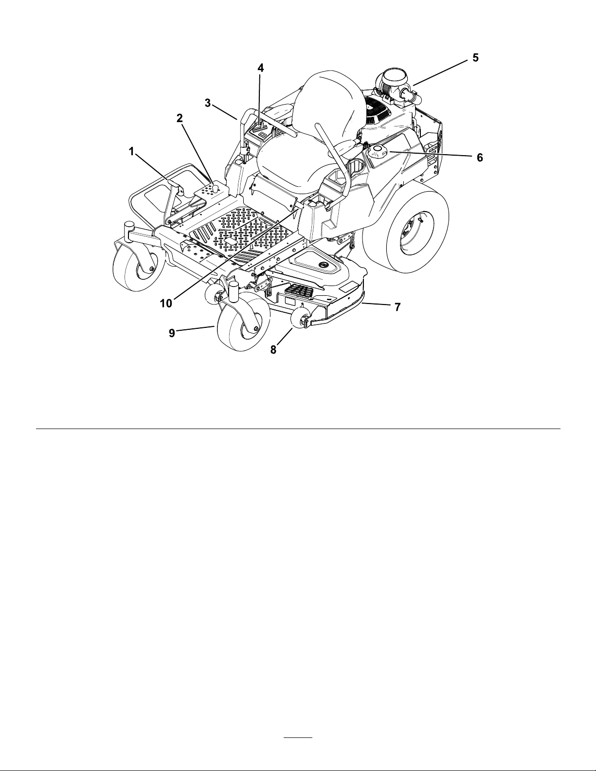
ProductOverview
1.Deck-liftpedal4.Controls
2.Height-of-cutpin
3.Motion-controllever6.Fuelcap
5.Engine8.Anti-scalproller
g297253
Figure5
7.Mowerdeck10.Parking-brakelever
9.Casterwheel
10

Controls
ChokeControl
Becomefamiliarwithallthecontrolsbeforeyoustart
theengineandoperatethemachine.
ControlPanel
Figure6
1.Hourmeter4.Keyswitch
2.Throttlecontrol5.Blade-controlswitch
(powertakeoff)
3.Chokecontrol
Usethechokecontroltostartacoldengine(Figure6).
HourMeter
Thehourmeterrecordsthenumberofhoursthe
enginehasoperated.Itoperateswhentheengine
isrunning.Usethesetimesforschedulingregular
maintenance(Figure6).
Motion-ControlLevers
Usethemotion-controlleverstodrivethemachine
forward,reverse,andturneitherdirection(Figure5).
Neutral-LockPosition
g297595
Movethemotion-controlleversoutwardfromthe
centertotheNEUTRAL-LOCKpositionwhenexiting
themachine(Figure22).Alwayspositionthe
motion-controlleversintotheNEUTRAL-LOCKposition
whenyoustopthemachineorleaveitunattended.
FuelGauge
Thefuelgaugedisplaystheamountoffuelinthetank
(Figure7).
Figure7
Parking-BrakeLever
Theparking-brakeleverislocatedontheleftsideof
theconsole(Figure5).Thebrakeleverengagesa
parkingbrakeonthedrivewheels.
Toengagetheparkingbrake,pulluptheleveruntilit
latchesintothedetentslot.
Todisengagetheparkingbrake,pulltheleveroutof
thedetentslotandtowardyou,thenpushitdown.
FootPedalDeck-LiftSystem
Thefootpedaldeck-liftsystemallowsyoutolower
andraisethedeckfromtheseatedposition.Y ou
canusethefootpedaltoliftthedeckbrieytoavoid
obstacles(Figure5).
KeySwitch
Thekeyswitch,usedtostartandshutofftheengine,
g238298
has3positions:OFF,RUN,andST ART(Figure6).
RefertoStartingtheEngine(page20).
1.Fuelgauge2.Fuel-tankcap
ThrottleControl
Thethrottlecontrolstheenginespeed,andithasa
continuous-variablesettingfromtheSLOWtoFAST
position(Figure6).
Blade-ControlSwitch(Power
Takeoff)
Theblade-controlswitch,representedbya
power-takeoff(PTO)symbol,engagesand
disengagespowertothemowerblades(Figure6).
11

Height-of-CutPin
Theheight-of-cutpinworkswiththefootpedaltolock
thedeckinaspeciccuttingheight.Adjusttheheight
ofcutonlywhenthemachineisnotmoving(Figure5).
Operation
Note:Determinetheleftandrightsidesofthe
machinefromthenormaloperatingposition.
Attachments/Accessories
AselectionofT oroapprovedattachmentsand
accessoriesisavailableforusewiththemachine
toenhanceandexpanditscapabilities.Contact
yourAuthorizedServiceDealerorauthorizedT oro
distributororgotowww.T oro.comforalistofall
approvedattachmentsandaccessories.
Toensureoptimumperformanceandcontinuedsafety
certicationofthemachine,useonlygenuineToro
replacementpartsandaccessories.Replacement
partsandaccessoriesmadebyothermanufacturers
couldbedangerous,andsuchusecouldvoidthe
productwarranty.
Specications
Specicationsanddesignaresubjecttochange
withoutnotice.
48inMower
Deck
Cuttingwidth122cm(48
Widthwith
deector
down
Widthwith
deector
raised
Length
Height
Weight
inches)
163cm(64
inches)
140cm(55
inches)
206cm(81
inches)
122cm(48
inches)
337kg(742
lb)
54inMower
Deck
137cm(54
inches)
178cm(70
inches)
155cm(61
inches)
206cm(81
inches)
122cm(48
inches)
344kg(758
lb)
60inMower
Deck
152cm(60
inches)
193cm(76
inches)
170cm(67
inches)
206cm(81
inches)
122cm(48
inches)
351kg(773
lb)
BeforeOperation
BeforeOperationSafety
GeneralSafety
•Donotallowchildrenoruntrainedpeopleto
operateorservicethemachine.Localregulations
mayrestricttheageoftheoperator.Theowner
isresponsiblefortrainingalloperatorsand
mechanics.
•Inspecttheareawhereyouwillusethemachine,
andremoveallobjectsthatcouldinterferewith
theoperationofthemachineorthatthemachine
couldthrow.
•Becomefamiliarwiththesafeoperationofthe
equipment,operatorcontrols,andsafetysigns.
•Checkthatoperator-presencecontrols,safety
switches,andguardsareattachedandworking
properly.Donotoperatethemachineunlessthey
arefunctioningproperly.
•Shutofftheengine,removethekey,andwait
forallmovingpartstostopbeforeleavingthe
operator’sposition.Allowthemachinetocool
beforeservicing,adjusting,fueling,cleaning,or
storingit.
•Beforemowing,inspectthemachinetoensure
thatthecuttingassembliesareworkingproperly .
•Evaluatetheterraintodeterminetheappropriate
equipmentandanyattachmentsoraccessories
requiredtooperatethemachineproperlyand
safely.
•Wearappropriateclothing,includingeye
protection;longpants;substantial,slip-resistant
footwear;andhearingprotection.Tiebacklong
hairanddonotwearlooseclothingorloose
jewelry.
•Donotcarrypassengersonthemachine.
•Keepbystandersandpetsawayfromthemachine
duringoperation.Shutoffthemachineand
attachment(s)ifanyoneentersthearea.
•Donotoperatethemachineunlessallguardsand
safetydevices,suchasthedeectorsandthe
entiregrasscatcher,areinplaceandfunctioning
properly.Replacewornordeterioratedpartswhen
necessary.
12

FuelSafety
•Fuelisextremelyammableandhighlyexplosive.
Areorexplosionfromfuelcanburnyouand
othersandcandamageproperty.
–Topreventastaticchargefromignitingthefuel,
placethecontainerand/ormachinedirectlyon
thegroundbeforelling,notinavehicleoron
anobject.
–Fillthefueltankoutdoorsonlevelground,in
anopenarea,andwhentheengineiscold.
Wipeupanyfuelthatspills.
–Donothandlefuelwhensmokingoraroundan
openameorsparks.
–Donotremovethefuelcaporaddfueltothe
tankwhiletheengineisrunningorhot.
–Ifyouspillfuel,donotattempttostartthe
engine.Avoidcreatingasourceofignitionuntil
thefuelvaporshavedissipated.
–Storefuelinanapprovedcontainerandkeep
itoutofthereachofchildren.
•Fuelisharmfulorfatalifswallowed.Long-term
exposuretovaporscancauseseriousinjuryand
illness.
–Avoidprolongedbreathingofvapors.
–Keepyourhandsandfaceawayfromthe
nozzleandthefuel-tankopening.
–Keepfuelawayfromyoureyesandskin.
•Donotstorethemachineorfuelcontainerwhere
thereisanopename,spark,orpilotlight,such
asonawaterheateroronotherappliances.
•Donotllcontainersinsideavehicleoronatruck
ortrailerbedwithaplasticliner.Alwaysplace
containersonthegroundandawayfromyour
vehiclebeforelling.
•Removetheequipmentfromthetruckortrailer
andrefuelitwhileitisontheground.Ifthisisnot
possible,thenrefuelfromaportablecontainer
ratherthanfromafuel-dispensernozzle.
•Donotoperatethemachinewithouttheentire
exhaustsysteminplaceandinproperworking
condition.
•Keepthefuel-dispensernozzleincontactwith
therimofthefueltankorcontaineropeningat
alltimesuntilfuelingiscomplete.Donotusea
nozzlelock-opendevice.
•Ifyouspillfuelonyourclothing,changeyour
clothingimmediately.
•Donotoverllthefueltank.Replacethefuelcap
andtightenitsecurely.
•Cleangrassanddebrisfromthecuttingunit,
mufer,drives,grasscatcher,andengine
compartmenttohelppreventres.Cleanupoilor
fuelspills.
AddingFuel
RecommendedFuel
TypeUnleadedgasoline
Minimumoctanerating
Ethanol
MethanolNone
MTBE(methyltertiarybutyl
ether)
OilDonotaddtothefuel
Useonlyclean,fresh(nomorethan30daysold),fuel
fromareputablesource.
UsingStabilizer/Conditioner
Usefuelstabilizer/conditionerinthemachinetokeep
thefuelfreshlongerwhenusedasdirectedbythe
fuel-stabilizermanufacturer.
Important:Donotusefueladditivescontaining
methanolorethanol.
Addtheamountoffuelstabilizer/conditionertofresh
fuelasdirectedbythefuel-stabilizermanufacturer.
FillingtheFuelTank
1.Parkthemachineonalevelsurface.
2.Engagetheparkingbrake.
3.Shutofftheengineandremovethekey.
4.Cleanaroundthefuel-tankcap.
5.Fillthefueltankuntilthefuelgaugereadsatthe
fullmark(Figure8).
Note:Donotllthefueltankcompletelyfull.
Theemptyspaceinthetankallowsthefuelto
expand.
87(US)or91(research
octane;outsidetheUS)
Nomorethan10%byvolume
Lessthan15%byvolume
13
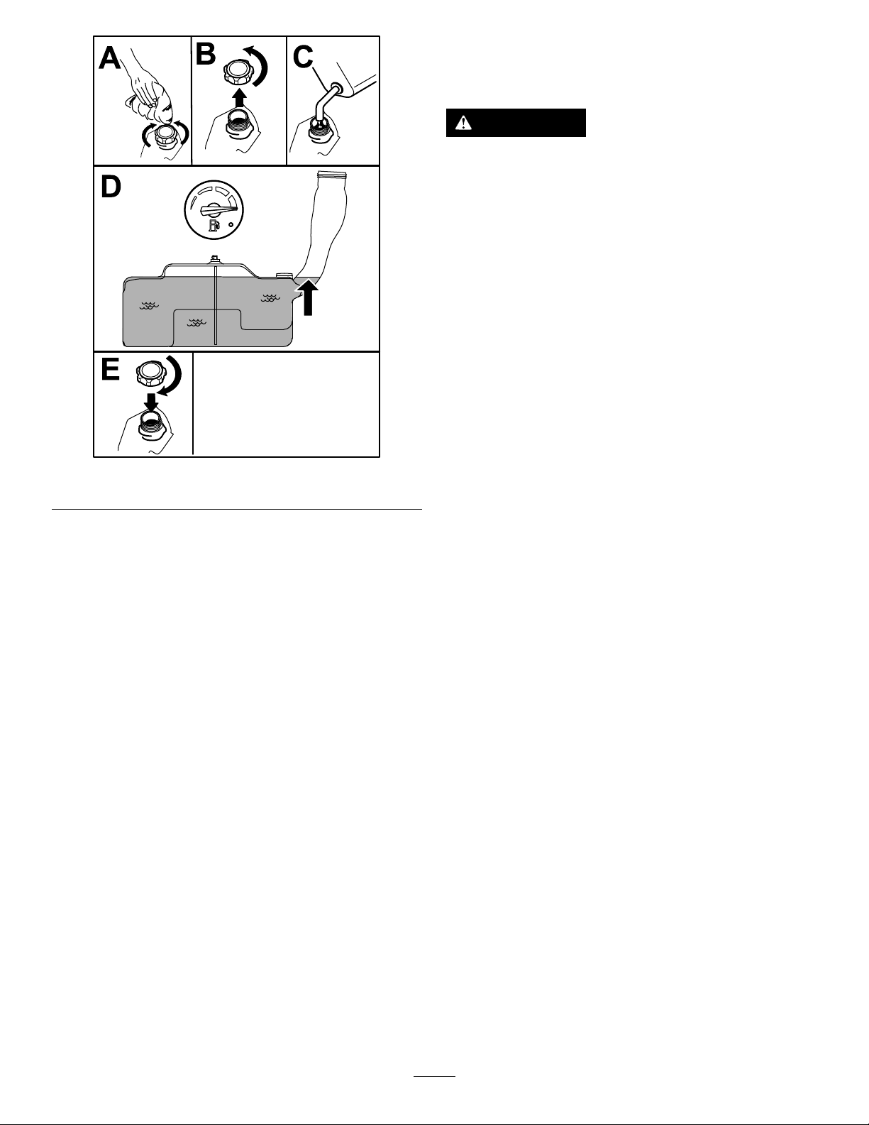
Figure8
UsingtheSafety-Interlock
System
WARNING
Ifthesafety-interlockswitchesare
disconnectedordamaged,themachinecould
operateunexpectedly,causingpersonal
injury.
•Donottamperwiththeinterlockswitches.
•Checktheoperationoftheinterlock
switchesdailyandreplaceanydamaged
switchesbeforeoperatingthemachine.
Understandingthe
Safety-InterlockSystem
Thesafety-interlocksystemisdesignedtopreventthe
enginefromstartingunless:
•Theblade-controlswitch(PTO)isdisengaged.
•Themotion-controlleversareintheNEUTRAL-LOCK
g197123
position.
•Theparkingbrakeisengaged.
PerformingDaily
Maintenance
Beforestartingthemachineeachday ,performthe
EachUse/DailyprocedureslistedinMaintenance
(page27).
BreakinginaNewMachine
Newenginestaketimetodevelopfullpower.Mower
decksanddrivesystemshavehigherfrictionwhen
new,placingadditionalloadontheengine.Allow
40to50hoursofbreak-intimefornewmachinesto
developfullpowerandbestperformance.
Thesafety-interlocksystemalsoisdesignedtoshut
offtheenginewheneverthecontrolleversareoutof
theNEUTRAL-LOCKpositionandyourisefromtheseat.
TestingtheSafety-Interlock
System
ServiceInterval:Beforeeachuseordaily
Testthesafety-interlocksystembeforeyouusethe
machineeachtime.Ifthesafetysystemdoesnot
operateasdescribedbelow,haveanAuthorized
ServiceDealerrepairthesafetysystemimmediately .
1.Sitontheseat,engagetheparkingbrake,and
movetheblade-controlswitch(PTO)totheON
position.Trystartingtheengine;theengine
shouldnotcrank.
2.Sitontheseat,engagetheparkingbrake,and
movetheblade-controlswitch(PTO)totheOFF
position.Moveeithermotion-controllever(out
oftheNEUTRAL-LOCKposition).Trystartingthe
engine;theengineshouldnotcrank.Repeatfor
othercontrollever.
3.Sitontheseat,engagetheparkingbrake,
movetheblade-controlswitch(PTO)totheOFF
position,andmovethemotion-controlleversto
theNEUTRAL-LOCKposition.Starttheengine.
Whiletheengineisrunning,releasetheparking
brake,engagetheblade-controlswitch(PTO),
andriseslightlyfromtheseat;theengineshould
shutoff.
14

4.Sitontheseat,engagetheparkingbrake,
movetheblade-controlswitch(PTO)totheOFF
position,andmovethemotion-controllevers
toNEUTRAL-LOCKposition.Starttheengine.
Whiletheengineisrunning,centereither
motion-controlleverandmoveitforwardor
reverse;theengineshouldshutoff.Repeatfor
othermotion-controllever.
5.Sitontheseat,disengagetheparkingbrake,
movetheblade-controlswitch(PTO)totheOFF
position,andmovethemotion-controlleversto
NEUTRAL-LOCKposition.Trystartingtheengine;
theengineshouldnotcrank.
PositioningtheSeat
Theseatcanmoveforwardandbackward.Position
theseatwhereyouhavethebestcontrolofthe
machineandaremostcomfortable(Figure9).
Adjustingthe
Motion-ControlLevers
AdjustingtheHeight
Youcanadjustthemotion-controllevershigheror
lowerformaximumcomfort(Figure10).
g027252
Figure10
Figure9
AdjustingtheTilt
Youcanadjustthemotion-controlleversforwardor
rearwardforyourcomfort.
1.Loosentheupperboltholdingthecontrollever
tothecontrol-armshaft.
2.Loosenthelowerboltjustenoughtopivotthe
controlleverforwardorrearward(Figure10).
g027632
3.Tightenbothboltstosecurethecontrolleverin
thenewposition.
4.Repeattheadjustmentfortheothercontrollever.
15

DuringOperation
DuringOperationSafety
GeneralSafety
•Theowner/operatorcanpreventandisresponsible
foraccidentsthatmaycausepersonalinjuryor
propertydamage.
•Useyourfullattentionwhileoperatingthe
machine.Donotengageinanyactivitythat
causesdistractions;otherwise,injuryorproperty
damagemayoccur.
•Donotoperatethemachinewhileill,tired,or
undertheinuenceofalcoholordrugs.
•Contactingthebladecanresultinseriouspersonal
injury.Shutofftheengine,removethekey,and
waitforallmovingpartstostopbeforeleavingthe
operatingposition.Whenyouturnthekeytothe
OFFposition,theengineshouldshutoffandthe
bladeshouldstop.Ifnot,stopusingyourmachine
immediatelyandcontactanAuthorizedService
Dealer.
•Operatethemachineonlyingoodvisibilityand
appropriateweatherconditions.Donotoperate
themachinewhenthereistheriskoflightning.
•Keepyourhandsandfeetawayfromthecutting
units.Keepclearofthedischargeopening.
•Donotmowwiththedischargedoorraised,
removed,oralteredunlessthereisa
grass-collectionsystemormulchkitinplaceand
workingproperly.
•Donotmowinreverseunlessitisabsolutely
necessary.Alwayslookdownandbehindyou
beforemovingthemachineinreverse.
•Useextremecarewhenapproachingblind
corners,shrubs,trees,orotherobjectsthatmay
blockyourview.
•Stopthebladeswheneveryouarenotmowing.
•Ifthemachinestrikesanobjectorstartstovibrate,
immediatelyshutofftheengine,removethekey
(ifequipped),andwaitforallmovingpartstostop
beforeexaminingthemachinefordamage.Make
allnecessaryrepairsbeforeresumingoperation.
•Slowdownandusecautionwhenmakingturns
andcrossingroadsandsidewalkswiththe
machine.Alwaysyieldtheright-of-way.
•Beforeyouleavetheoperatingposition,dothe
following:
–Parkthemachineonalevelsurface.
–Disengagethepowertakeoffandlowerthe
attachments.
–Engagetheparkingbrake.
–Shutofftheengineandremovethekey.
–Waitforallmovingpartstostop.
•Operatetheengineonlyinwell-ventilatedareas.
Exhaustgasescontaincarbonmonoxide,which
islethalifinhaled.
•Neverleavearunningmachineunattended.
•Attachtowedequipmenttothemachineonlyat
thehitchpoint.
•Donotoperatethemachineunlessallguardsand
safetydevices,suchasthedeectorsandthe
entiregrasscatcher,areinplaceandfunctioning
properly.Replacewornordeterioratedpartswhen
necessary.
•Useonlyaccessoriesandattachmentsapproved
byToro.
•Thismachineproducessoundlevelsinexcess
of85dBAattheoperator’searandcancause
hearinglossthroughextendedperiodsof
exposure.
g229846
Figure11
1.Wearhearingprotection.
•Cleangrassanddebrisfromthecuttingunit,
drives,mufer,andenginetohelppreventres.
•Starttheenginewithyourfeetwellawayfromthe
blades.
•Neverraisethemowerdeckwhilethebladesare
moving.
•Beawareofthemowerdischargepathanddirect
thedischargeawayfromothers.Avoiddischarging
materialagainstawallorobstructionbecausethe
materialmayricochetbacktowardyou.
•Stoptheblades,slowdownthemachine,anduse
cautionwhencrossingsurfacesotherthangrass
orwhentransportingthemachinetoandfromthe
operatingarea.
•Donotchangetheenginegovernorspeedor
overspeedtheengine.
•Childrenareoftenattractedtothemachineand
themowingactivity.Neverassumethatchildren
willremainwhereyoulastsawthem.
•Keepchildrenoutoftheoperatingareaandunder
thewatchfulcareofaresponsibleadultotherthan
theoperator.
•Bealertandshutoffthemachineifchildrenenter
theoperatingarea.
16

•Beforebackinguporturningthemachine,look
downandallaroundforsmallchildren.
•Donotcarrychildrenonthemachine,evenwhen
thebladesarenotmoving.Childrencouldfall
offandbeseriouslyinjuredorpreventyoufrom
safelyoperatingthemachine.Childrenwhohave
beengivenridesinthepastcouldappearinthe
operatingareawithoutwarningandberunoveror
backedoverbythemachine.
SlopeSafety
•Slopesareamajorfactorrelatedtolossofcontrol
androlloveraccidents,whichcanresultinsevere
injuryordeath.Theoperatorisresponsiblefor
safeslopeoperation.Operatingthemachineon
anysloperequiresextracaution.Beforeusingthe
machineonaslope,dothefollowing:
–Reviewandunderstandtheslopeinstructions
inthemanualandonthemachine.
–Useanangleindicatortodeterminethe
approximateslopeangleofthearea.
–Neveroperateonslopesgreaterthan15°.
–Evaluatethesiteconditionsofthedayto
determineiftheslopeissafeformachine
operation.Usecommonsenseandgood
judgmentwhenperformingthisevaluation.
Changesintheterrain,suchasmoisture,can
quicklyaffecttheoperationofthemachineon
aslope.
•Identifyhazardsatthebaseoftheslope.Do
notoperatethemachineneardrop-offs,ditches,
embankments,water,orotherhazards.The
machinecouldsuddenlyrolloverifawheelgoes
overtheedgeortheedgecollapses.Keepasafe
distance(twicethewidthofthemachine)between
themachineandanyhazard.Useawalk-behind
machineorahandtrimmertomowthegrassin
theseareas.
•Avoidstarting,stopping,orturningthemachineon
slopes.Avoidmakingsuddenchangesinspeedor
direction;turnslowlyandgradually.
•Donotoperateamachineunderanyconditions
wheretraction,steering,orstabilityisinquestion.
Beawarethatoperatingthemachineonwet
grass,acrossslopes,ordownhillmaycausethe
machinetolosetraction.Lossoftractiontothe
drivewheelsmayresultinslidingandalossof
brakingandsteering.Themachinecanslideeven
ifthedrivewheelsarestopped.
•Removeormarkobstaclessuchasditches,holes,
ruts,bumps,rocks,orotherhiddenhazards.T all
grasscanhideobstacles.Uneventerraincould
overturnthemachine.
•Useextracarewhileoperatingwithaccessoriesor
attachments,suchasgrass-collectionsystems.
Thesecanchangethestabilityofthemachine
andcausealossofcontrol.Followdirectionsfor
counterweights.
•Ifpossible,keepthedeckloweredtotheground
whileoperatingonslopes.Raisingthedeckwhile
operatingonslopescancausethemachineto
becomeunstable.
Figure12
1.SafeZone—usethe
machinehereonslopes
lessthan15°oratareas.
2.DangerZone—usea
walk-behindmowerand/or
ahandtrimmeronslopes
greaterthan15°andnear
drop-offsorwater.
3.Water
4.W=Widthofthemachine
5.Keepasafedistance
(twicethewidthofthe
machine)betweenthe
machineandanyhazard.
TowingSafety
•Donotattachtowedequipmentexceptatthehitch
point.
•Donotusethemachineasatowingvehicleunless
ithasahitchinstalled.
•Donotexceedtheweightlimitsfortowed
equipmentandtowingonslopes.Thetowed
weightmustnotexceedtheweightofthemachine
andoperator.
•Neverallowchildrenorothersnearthetowed
equipment.
•Onslopes,theweightofthetowedequipmentmay
causelossoftraction,increasedriskofrollover,
andlossofcontrol.Reducethetowedweightand
slowdown.
•Thestoppingdistancemayincreasewiththe
weightofatowedload.Travelslowlyandallow
extradistancetostop.
•Makewideturnstokeeptheattachmentclearof
themachine.
g22911 1
17
OperatingtheParking
EngagingtheBlade-Control
Brake
Alwaysengagetheparkingbrakewhenyoustopthe
machineorleaveitunattended.
EngagingtheParkingBrake
Parkthemachineonalevelsurface.
Figure13
Switch(PTO)
g008945
Figure15
Note:Alwaysengagethebladeswiththethrottlein
theFASTposition(Figure16).
g188778
DisengagingtheParkingBrake
Todisengagetheparkingbrake,pulltheleveroutof
thedetentslotandtowardyou,thenpushitdown
(Figure14).
Figure14
1.Pushtheparkingbrake
outofthedetentslotand
towardyou.
2.Pushtheparkingbrake
down.
g295538
Figure16
Disengagingthe
Blade-ControlSwitch
(PTO)
g188777
g009174
Figure17
18

OperatingtheThrottle
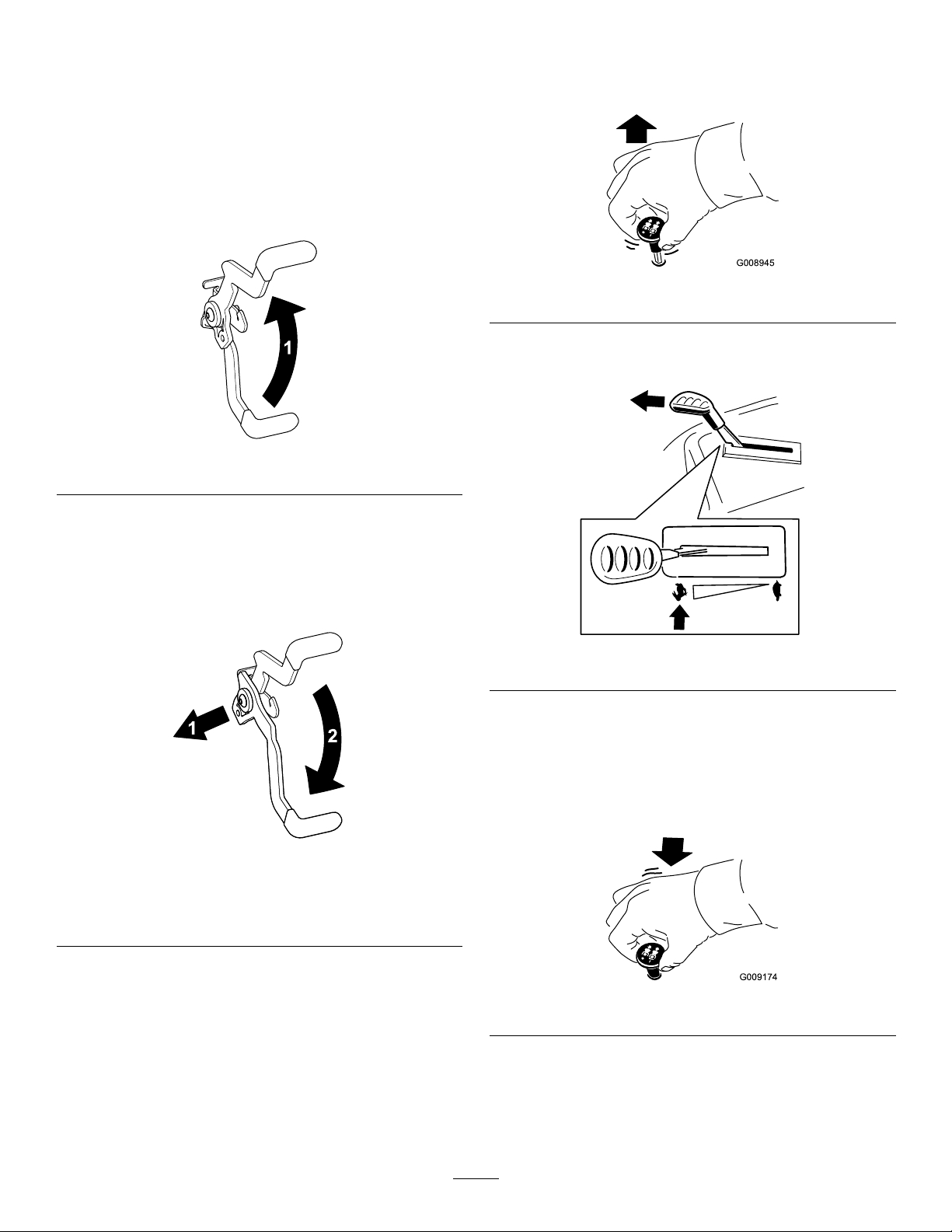
OperatingtheKeySwitch
YoucanmovethethrottlecontrolbetweentheFAST
andSLOWpositions(Figure18).
AlwaysusetheFASTpositionwhenengagingthePTO.
Figure18
OperatingtheChoke
Usethechoketostartacoldengine.
1.Pullupthechokeknobtoengagethechoke
beforeusingthekeyswitch(Figure19).
1.TurnthekeytotheST ARTposition(Figure20).
Note:Whentheenginestarts,releasethekey.
Important:Donotengagethestartermotor
formorethan5secondsatatime.Ifthe
enginefailstostart,wait10secondsbetween
attempts.Failuretofollowtheseinstructions
canburnoutthestartermotor.
Note:Youmayneedmultipleattemptstostart
theenginewhenyoustartitthersttimeafter
thefuelsystemhasbeenwithoutfuelcompletely.
g295539
g008947
Figure20
Note:Ensurethatyoufullyengagethechoke.
Youmayneedtoholdtheknobupwhenyou
usethekeyswitch.
2.Pushdownthechoketodisengagethechoke
aftertheenginehasstarted(Figure19).
2.TurnthekeytotheSTOPpositiontoshutoffthe
engine.
Figure19
1.ONposition2.OFFposition
g295540
19

StartingtheEngine
ShuttingOfftheEngine
Note:Awarmorhotenginemaynotrequirechoking.
Important:Donotengagethestarterformore
than5secondsatatime.Engagingthestarter
motorformorethan5secondscandamagethe
startermotor.Iftheenginefailstostart,wait10
secondsbeforeoperatingtheenginestarteragain.
1.Disengagethebladesbymovingthe
blade-controlswitchtotheOFFposition(Figure
21).
2.Engagetheparkingbrake.
3.MovethethrottlecontroltotheFASTposition.
4.TurnthekeytotheOFFpositionandremove
thekey.
CAUTION
Childrenorbystandersmaybeinjuredifthey
moveorattempttooperatethemachinewhile
itisunattended.
Alwaysremovethekeyandengagethe
parkingbrakewhenleavingthemachine
unattended.
UsingtheMotion-Control
Levers
Figure21
g297307
g004532
Figure22
1.Motion-control
lever—NEUTRAL-LOCK
position
2.Center,unlockedposition5.Frontofmachine
3.Forward
20
4.Backward

DrivingtheMachine
Thedrivewheelsturnindependently,poweredby
hydraulicmotorsoneachaxle.Y oucanturn1side
inreversewhileyouturntheotherforward,causing
themachinetospinratherthanturn.Thisgreatly
improvesthemachinemaneuverabilitybutmay
requiresometimeforyoutoadapttohowitmoves.
Thethrottlecontrolregulatestheenginespeedas
measuredinrpm(revolutionsperminute).Place
thethrottlecontrolintheFASTpositionforbest
performance.Alwaysoperateinthefullthrottle
positionwhenmowing.
WARNING
Themachinecanspinveryrapidly.You
maylosecontrolofthemachineandcause
personalinjuryordamagetothemachine.
•Usecautionwhenmakingturns.
•Slowthemachinedownbeforemaking
sharpturns.
DrivingForward
Note:Theengineshutsoffwhenyoumovethe
traction-controlwiththeparkingbrakeengaged.
Tostopthemachine,pullthemotion-controllevers
totheNEUTRALposition.
1.Disengagetheparkingbrake;referto
DisengagingtheParkingBrake(page18).
2.Movetheleverstothecenter,unlockedposition.
3.T ogoforward,slowlypushthemotion-control
leversforward(Figure23).
g008952
Figure23
DrivingBackward
1.Movetheleverstothecenter,unlockedposition.
2.T ogobackward,slowlypullthemotion-control
leversrearward(Figure24).
g008953
Figure24
21

UsingtheSideDischarge
AdjustingtheHeightofCut
Themowerhasahingedgrassdeectorthat
dispersesclippingstothesideanddowntowardthe
turf.
DANGER
Withoutagrassdeector,dischargecover,or
acompletegrass-catcherassemblymounted
inplace,youandothersareexposedtoblade
contactandthrowndebris.Contactwith
rotatingmowerblade(s)andthrowndebris
willcauseinjuryordeath.
•Neverremovethegrassdeectorfromthe
mowerdeckbecausethegrassdeector
routesmaterialdowntowardtheturf.Ifthe
grassdeectoriseverdamaged,replaceit
immediately.
•Neverputyourhandsorfeetunderthe
mowerdeck.
•Nevertrytoclearthedischargearea
ormowerbladesunlessyoumovethe
blade-controlswitch(PTO)totheOFF
position,rotatethekeyswitchtotheOFF
position,andremovethekeyfromthekey
switch.
Themachineisequippedwithafootpedaldeck-lift
system.Y oucanusethefootpedaltoliftthedeck
brieytoavoidobstaclesandtoraisethedeck.
Youcanadjusttheheightofcutfrom38to114mm
(1-1/2to4-1/2inches)in6mm(1/4inch)increments
bymovingtheheight-of-cutpinintodifferenthole
locations.
1.Pushonthedeck-liftpedalwithyourfoottoraise
themowerdeck.
2.T oadjust,removethepinfromtheheight-of-cut
bracket(Figure25).
3.Selectaholeintheheight-of-cutsystem
correspondingtothedesiredheightofcutand
insertthepin(Figure25).
4.Lowerthedeckslowlyuntilthelevermakes
contactwiththepin.
•Makesurethatthegrassdeectorisinthe
downposition.
1.Deck-liftpedal
2.Height-of-cutpositions
g297360
Figure25
3.Pin
22

AdjustingtheAnti-Scalp
OperatingTips
Rollers
Wheneveryouchangetheheightofcut,adjustthe
heightoftheanti-scalprollers.
Note:Adjusttheanti-scalprollerssothattherollers
donottouchthegroundinnormal,atmowingareas.
1.Parkthemachineonalevelsurface,disengage
theblade-controlswitchandengagetheparking
brake;refertoEngagingtheParkingBrake
(page18).
2.Shutofftheengine,removethekey ,andwait
forallmovingpartstostopbeforeleavingthe
operatingposition.
3.Adjusttheanti-scalprollersasshowninFigure
26.
UsingtheFastThrottleSetting
Forbestmowingandmaximumaircirculation,operate
theengineattheFASTposition.Airisrequiredto
thoroughlycutgrassclippings,sodonotsetthe
height-of-cutsolowastototallysurroundthemower
deckinuncutgrass.Alwaystrytohave1sideofthe
mowerdeckfreefromuncutgrass,whichallowsair
tobedrawnintothemowerdeck.
CuttingaLawnfortheFirstTime
Cutgrassslightlylongerthannormaltoensurethat
thecuttingheightofthemowerdeckdoesnotscalp
anyunevenground.However,thecuttingheight
usedinthepastisgenerallythebestonetouse.
Whencuttinggrasslongerthan15cm(6inches)tall,
youmaywanttocutthelawntwicetoensurean
acceptablequalityofcut.
CuttingaThirdoftheGrassBlade
Itisbesttocutonlyaboutathirdofthegrassblade.
Cuttingmorethanthatisnotrecommendedunless
grassissparse,oritislatefallwhengrassgrows
moreslowly.
Figure26
1.Anti-scalproller4.Flangenut
2.Spacer
3.Bushing
5.Bolt
AlternatingtheMowingDirection
g029955
Alternatethemowingdirectiontokeepthegrass
standingstraight.Thisalsohelpsdisperseclippings,
whichenhancesdecompositionandfertilization.
MowingatCorrectIntervals
Grassgrowsatdifferentratesatdifferenttimesof
theyear.Tomaintainthesamecuttingheight,mow
moreofteninearlyspring.Asthegrassgrowthrate
slowsinmidsummer,mowlessfrequently.Ifyou
cannotmowforanextendedperiod,rstmowata
highcuttingheight,thenmowagain2dayslaterata
lowerheightsetting.
UsingaSlowerCuttingSpeed
Toimprovecutquality,useaslowergroundspeed
incertainconditions.
AvoidingCuttingTooLow
Whenmowinguneventurf,raisethecuttingheight
toavoidscalpingtheturf.
StoppingtheMachine
Ifyoumuststoptheforwardmotionofthemachine
whilemowing,aclumpofgrassclippingsmay
23

dropontoyourlawn.T oavoidthis,moveontoa
previouslycutareawiththebladesengagedoryou
candisengagethemowerdeckwhilemovingforward.
KeepingtheUndersideofthe
AfterOperation
AfterOperationSafety
MowerDeckClean
Cleanclippingsanddirtfromtheundersideofthe
mowerdeckaftereachuse.Ifgrassanddirtbuildup
insidethemowerdeck,cuttingqualitywilleventually
becomeunsatisfactory.
MaintainingtheBlade(s)
Maintainasharpbladethroughoutthecuttingseason
becauseasharpbladecutscleanlywithouttearingor
shreddingthegrassblades.T earingandshredding
turnsgrassbrownattheedges,whichslowsgrowth
andincreasesthechanceofdisease.Checkthe
mowerbladesaftereachuseforsharpness,and
foranywearordamage.Filedownanynicksand
sharpenthebladesasnecessary.Ifabladeis
damagedorworn,replaceitimmediatelywitha
genuineT ororeplacementblade.
GeneralSafety
•Shutofftheengine,removethekey,andwait
forallmovingpartstostopbeforeleavingthe
operator’sposition.Allowthemachinetocool
beforeservicing,adjusting,fueling,cleaning,or
storingit.
•Cleangrassanddebrisfromthecuttingunit,
mufer,drives,grasscatcher,andengine
compartmenttohelppreventres.Cleanupoilor
fuelspills.
•Shutoffthefuelandremovethekeybeforestoring
ortransportingthemachine.
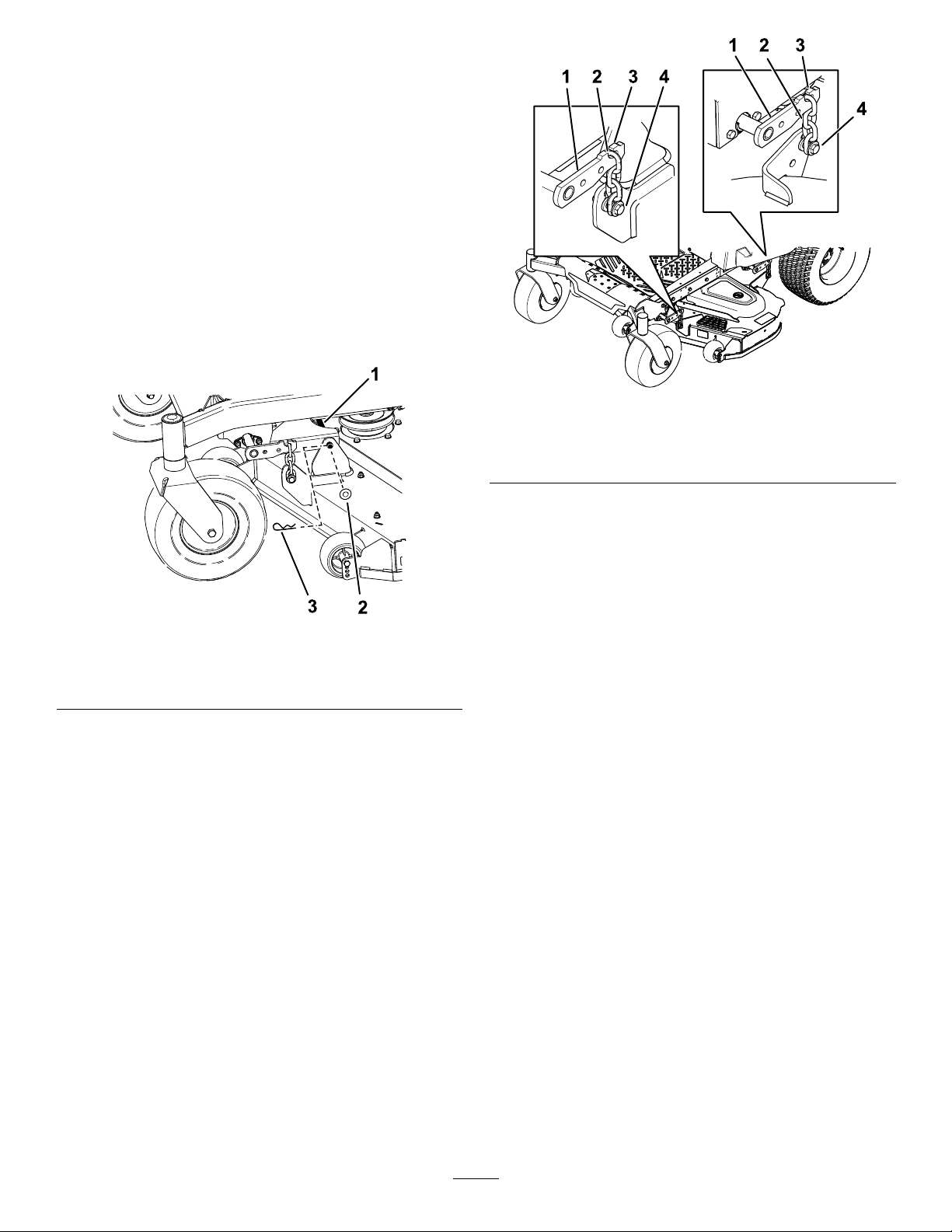
PushingtheMachineby
Hand
Important:Alwayspushthemachinebyhand.
Donottowthemachine,becausetowingmay
damageit.
PushingtheMachine
1.Parkthemachineonalevelsurface,disengage
theblade-controlswitch,andengagetheparking
brake.
2.Shutofftheengine,removethekey ,andwait
forallmovingpartstostopbeforeleavingthe
operatingposition.
3.Locatethebypassleversontheframeonboth
sidesoftheengine.
4.Movethebypassleversforwardthroughthekey
holeanddowntolocktheminplace(Figure27).
Note:Dothisforeachlever.
5.Disengagetheparkingbrake.
24

1.Bypass-leverlocations
2.Leverpositionfor
operatingthemachine
Figure27
3.Leverpositionforpushing
themachine
TransportingtheMachine
Useaheavy-dutytrailerortrucktotransportthe
machine.Useafull-widthramp.Ensurethatthetrailer
ortruckhasallthenecessarybrakes,lighting,and
markingasrequiredbylaw.Pleasecarefullyreadall
thesafetyinstructions.Knowingthisinformationcould
helpyouorbystandersavoidinjury.Refertoyour
localordinancesfortrailerandtie-downrequirements.
WARNING
Drivingonthestreetorroadwaywithout
g298692
turnsignals,lights,reectivemarkings,ora
slow-moving-vehicleemblemisdangerous
andcanleadtoaccidents,causingpersonal
injury.
Donotdrivethemachineonapublicstreet
orroadway.
6.Whennished,engagetheparkingbrake.
OperatingtheMachine
Movethebypassleversrearwardthroughthekeyhole
anddowntolocktheminplaceasshowninFigure27.
Note:Dothisforeachlever.
SelectingaTrailer
WARNING
Loadingamachineontoatrailerortruck
increasesthepossibilityoftip-overandcould
causeseriousinjuryordeath(Figure28).
•Useonlyafull-widthramp;donotuse
individualrampsforeachsideofthe
machine.
•Donotexceeda15-degreeanglebetween
therampandthegroundorbetweenthe
rampandthetrailerortruck.
•Ensurethatthelengthoftherampisat
least4timesaslongastheheightofthe
trailerortruckbedtotheground.This
ensuresthattherampangledoesnot
exceed15degreesonatground.
25
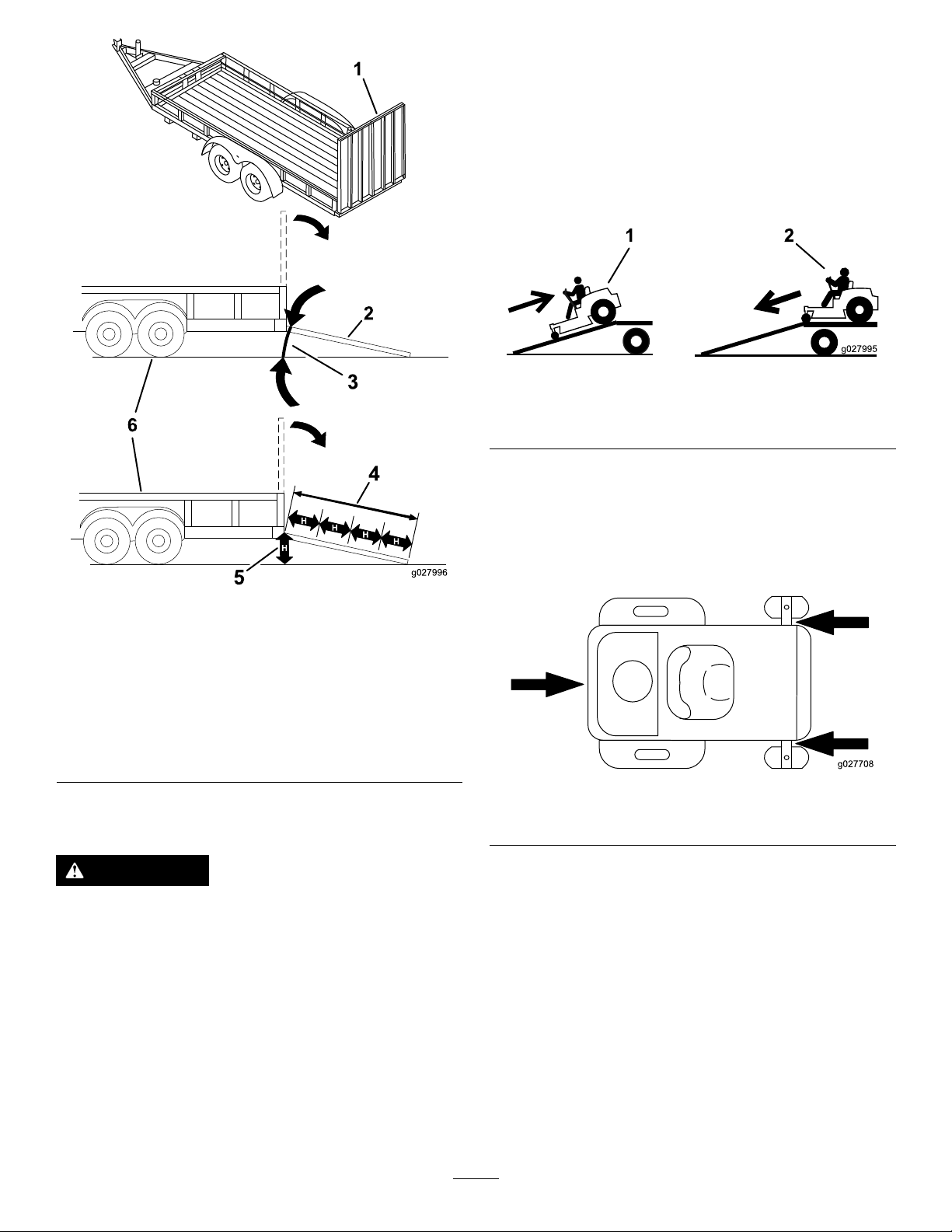
1.Ifusingatrailer,connectittothetowingvehicle
andconnectthesafetychains.
2.Ifapplicable,connectthetrailerbrakesand
lights.
3.Lowertheramp,ensuringthattheangle
betweentherampandthegrounddoesnot
exceed15degrees(Figure28).
4.Backthemachineuptheramp(Figure29).
Figure29
g027995
1.Full-widthrampinstowed
position
2.Sideviewoffull-width
rampinloadingposition
3.Notgreaterthan
15degrees
LoadingtheMachine
Figure28
4.Rampisatleast4times
aslongastheheightof
thetrailerortruckbedto
theground
5.H=heightofthetraileror
truckbedtotheground
6.Trailer
1.Backthemachineupthe
ramp.
2.Drivethemachineforward
downtheramp.
5.Shutofftheengine,removethekey,andengage
theparkingbrake.
6.Tiedownthemachinenearthefrontcaster
wheelsandtherearbumperwithstraps,chains,
cable,orropes(Figure30).Refertolocal
regulationsfortie-downrequirements.
g027996
g027708
Figure30
1.Tie-downloops
WARNING
Loadingamachineontoatrailerortruck
increasesthepossibilityoftip-overandcould
causeseriousinjuryordeath.
•Useextremecautionwhenoperatinga
machineonaramp.
•Backthemachineuptherampanddriveit
forwarddowntheramp.
•Avoidsuddenaccelerationordeceleration
whiledrivingthemachineonarampas
thiscouldcausealossofcontrolora
tip-oversituation.
UnloadingtheMachine
1.Lowertheramp,ensuringthattheangle
betweentherampandthegrounddoesnot
exceed15degrees(Figure28).
2.Drivethemachineforwarddowntheramp
(Figure29).
26

Maintenance
Note:Determinetheleftandrightsidesofthemachinefromthenormaloperatingposition.
MaintenanceSafety
•Ifyouleavethekeyintheswitch,someonecould
accidentlystarttheengineandseriouslyinjureyou
orotherbystanders.Removethekeyfromthe
switchbeforeyouperformanymaintenance.
•Beforeyouleavetheoperator’sposition,dothe
following:
–Parkthemachineonalevelsurface.
–Disengagethedrives.
–Engagetheparkingbrake.
–Shutofftheengineandremovethekey.
–Allowmachinecomponentstocoolbefore
performingmaintenance.
•Donotallowuntrainedpersonneltoservicethe
machine.
•Keepyourhandsandfeetawayfrommoving
partsorhotsurfaces.Ifpossible,donotmake
adjustmentswiththeenginerunning.
•Carefullyreleasepressurefromcomponentswith
storedenergy.
•Checktheparkingbrakeoperationfrequently.
Adjustandserviceitasrequired.
•Nevertamperwithsafetydevices.Checktheir
properoperationregularly.
•Cleangrassanddebrisfromthecuttingunit,
mufer,drives,grasscatcher,andengine
compartmenttopreventres.
•Cleanupoilorfuelspillsandremovefuel-soaked
debris.
•Donotrelyonhydraulicormechanicaljacksto
supportthemachine;supportthemachinewith
jackstandswheneveryouraisethemachine.
•Keepallpartsingoodworkingcondition
andallhardwaretightened,especiallythe
blade-attachmenthardware.Replaceallwornor
damageddecals.
•Disconnectthebatterybeforerepairingthe
machine.Disconnectthenegativeterminalrst
andthepositivelast.Connectthepositiveterminal
rstandthenegativelast.
•Toensureoptimumperformance,useonly
genuineT ororeplacementpartsandaccessories.
Replacementpartsandaccessoriesmadeby
othermanufacturerscouldbedangerous,and
suchusecouldvoidtheproductwarranty.
27

RecommendedMaintenanceSchedule(s)
MaintenanceService
Interval
Aftertherst5hours
Beforeeachuseordaily
Every25hours
Every100hoursoryearly,
whichevercomesrst
Every200hoursor2years,
whichevercomesrst
Every250hours
Every300hours
Beforestorage
MaintenanceProcedure
•Changetheengineoilandlter.
•Checkthesafety-interlocksystem.
•Checktheengine-oillevel.
•Cleantheairintakescreen.
•Inspecttheblades.
•Inspectthegrassdeectorfordamage.
•Checktirepressure.
•Checkthebeltsforwearorcracks.
•Changetheengineoilandoillter(moreoftenindirtyordustyconditions).
•Checkthesparkplug(s).
•Checkthein-linefuellter.
•Replacethesparkplug(s).
•Replacethein-linefuellter.
•Replacetheairlter(moreoftenindirtyordustyconditions).
•Checkandadjustthevalveclearance.ContactanAuthorizedServiceDealer.
•Chargethebatteryanddisconnectthebatterycables.
•Performallmaintenanceprocedureslistedabovebeforestorage.
•Paintanychippedsurfaces.
CAUTION
Ifyouleavethekeyintheswitch,someonecouldaccidentlystarttheengineandseriously
injureyouorotherbystanders.
Shutofftheengineandremovethekeyfromtheswitchbeforeyouperformanymaintenance.
28
EngineMaintenance
Note:Avoidknockingthelterintothesideof
thebody.
EngineSafety
•Keepyourhands,feet,face,clothing,andother
bodypartsawayfromthemuferandotherhot
surfaces.Allowenginecomponentstocoolbefore
performingmaintenance.
•Donotchangetheenginegovernorspeedor
overspeedtheengine.
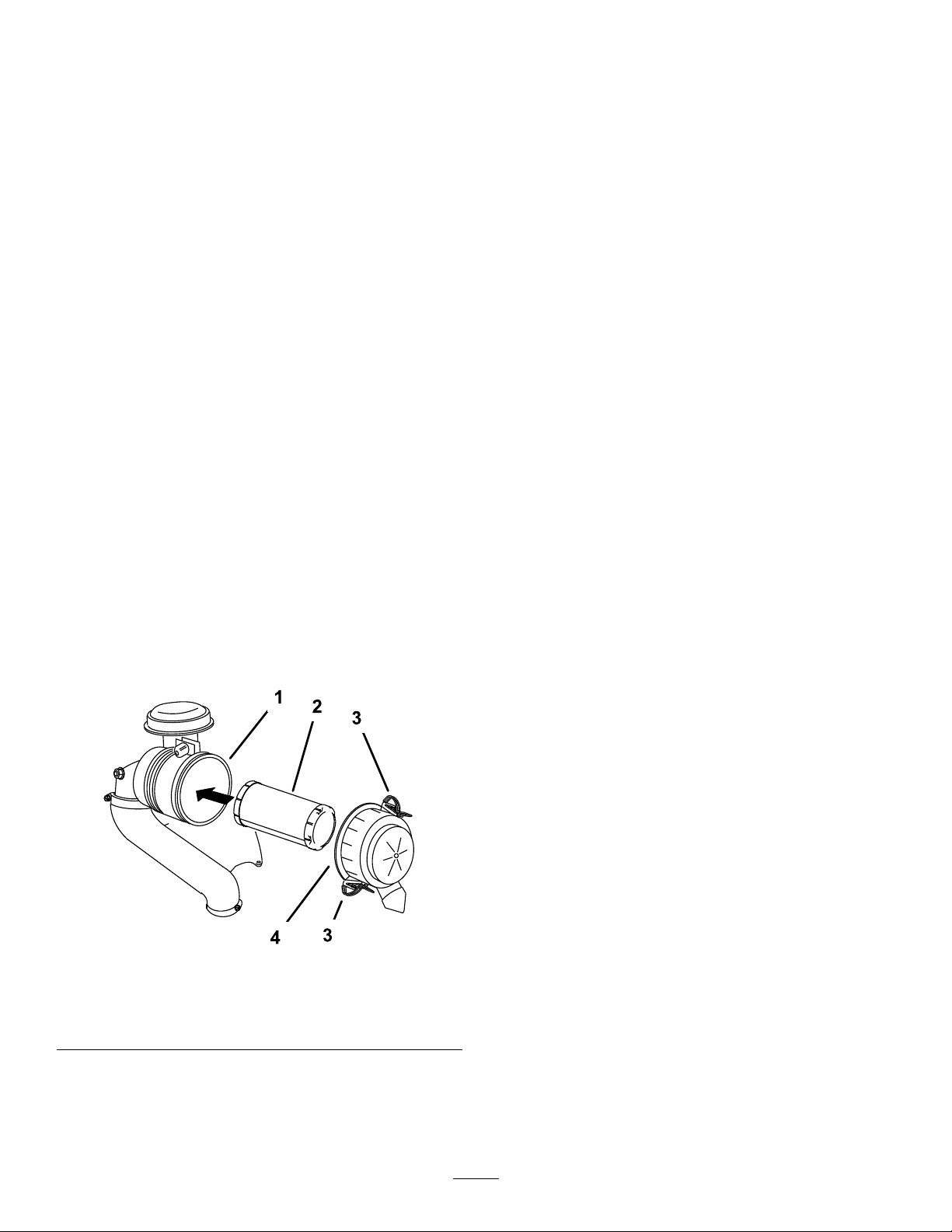
ServicingtheAirCleaner
ServiceInterval:Every250hours/Y early(whichever
comesrst)—Replacetheair
lter(moreoftenindirtyordusty
conditions).
Note:Servicetheaircleanermorefrequentlyif
operatingconditionsareextremelydustyorsandy .
RemovingtheFilter
1.Parkthemachineonalevelsurface,disengage
theblade-controlswitch(PTO),andengagethe
parkingbrake.
2.Shutofftheengine,removethekey ,andwait
forallmovingpartstostopbeforeleavingthe
operatingposition.
3.Releasethelatchesontheaircleanerandpull
theair-cleanercoverofftheair-cleanerbody
(Figure32).
InspectingtheFilter
Inspectthelterfordamagebylookingintothelter
whileshiningabrightlightontheoutsideofthelter.
Ifthelterisdirty ,bent,ordamaged,replaceit.
Note:Holesinthelterappearasbrightspots.Do
notcleanthelter.
InstallingtheFilter
Important:Topreventenginedamage,always
operatetheenginewiththeairlterandthecover
installed.
1.Ifyouareinstallinganewlter,checkthelter
forshippingdamage.
Note:Donotuseadamagedlter.
2.Carefullyslidethelterintotheair-cleanerbody
(Figure32).
Note:Ensurethatthelterisfullyseatedby
pushingontheouterrimwhileinstallingit.
Important:Donotpressonthesoft,inside
areaofthelter.
3.Installtheair-cleanercoverandsecurethe
latches(Figure32).
Figure31
1.Air-cleanerbody3.Latch
2.Filter4.Air-cleanercover
4.Cleantheinsideoftheair-cleanercoverwith
compressedair.
5.Gentlyslidethelteroutoftheair-cleanerbody
(Figure32).
g230914
29
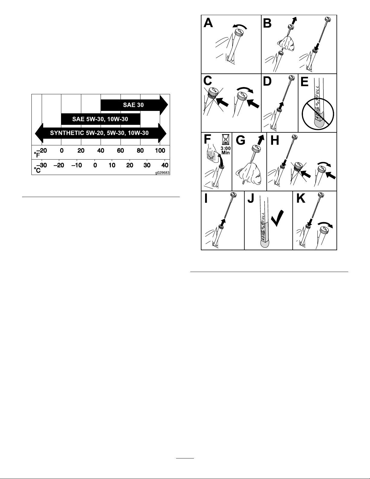
ServicingtheEngineOil
Engine-OilSpecications
OilType:Detergentoil(APIserviceSF ,SG,SH,SJ,
orSL)
CrankcaseCapacity:2.4L(81oz)withoillter
Viscosity:Seethetablebelow.
Figure32
g029683
CheckingtheEngine-OilLevel
ServiceInterval:Beforeeachuseordaily
Note:Checktheoilwhentheengineiscold.
Important:Ifyouoverllorunderlltheengine
crankcasewithoilandruntheengine,youmay
damagetheengine.
1.Parkthemachineonalevelsurface,disengage
theblade-controlswitch(PTO),andengagethe
parkingbrake.
2.Shutofftheengine,removethekey ,andwait
forallmovingpartstostopbeforeleavingthe
operatingposition.
Note:Ensurethattheengineiscoolsothatthe
oilhashadtimetodrainintothesump.
3.T okeepdirt,grassclippings,etc.,outofthe
engine,cleantheareaaroundtheoil-llcapand
dipstickbeforeremovingit(Figure33).
g311705
Figure33
ChangingtheEngineOilandOil
Filter
ServiceInterval:Aftertherst5hours/Afterthe
rstmonth(whichevercomes
rst)—Changetheengineoiland
lter.
Every100hoursoryearly,whichevercomes
rst—Changetheengineoilandoillter(more
oftenindirtyordustyconditions).
1.Parkthemachineonalevelsurfacetoensure
thattheoildrainscompletely.
2.Disengagetheblade-controlswitch(PTO)and
engagetheparkingbrake.
3.Shutofftheengine,removethekey ,andwait
forallmovingpartstostopbeforeleavingthe
operatingposition.
4.Draintheoilfromtheengine.
30

5.Changetheengine-oillter(Figure35).
Note:Ensurethattheoil-ltergaskettouches
theengineandthenturnthelteranextra3/4
turn.
g027799
Figure34
g027477
Figure35
6.Slowlypourapproximately80%ofthespecied
oilintothellertubeandslowlyaddthe
additionaloiltobringittotheFullmark(Figure
36).
g029570
31

Figure36
7.Disposeoftheusedoilatarecyclingcenter.
ServicingtheSparkPlug
ServiceInterval:Every100hoursoryearly,
whichevercomesrst—Checkthe
sparkplug(s).
Every200hoursor2years,whichevercomes
rst—Replacethesparkplug(s).
g027478
Figure37
CheckingtheSparkPlug
Important:Donotcleanthesparkplug(s).
Alwaysreplacethesparkplug(s)whenithasa
blackcoating,wornelectrodes,anoilylm,or
cracks.
Ifyouseelightbrownorgrayontheinsulator,the
engineisoperatingproperly.Ablackcoatingonthe
g235264
insulatorusuallymeanstheaircleanerisdirty .
Setthegapto0.75mm(0.03inch).
g206628
Figure38
Ensurethattheairgapbetweenthecenterandside
electrodesiscorrectbeforeinstallingthesparkplug.
Useasparkplugwrenchforremovingandinstalling
thesparkplugandagappingtoolorfeelergaugeto
checkandadjusttheairgap.Installanewsparkplug
ifnecessary.
Type:Champion
®
RN9YCorNGK
®
BPR6ES
Airgap:0.76mm(0.03inch)
RemovingtheSparkPlug
1.Parkthemachineonalevelsurface,disengage
theblade-controlswitch(PTO),andengagethe
parkingbrake.
2.Shutofftheengine,removethekey ,andwait
forallmovingpartstostopbeforeleavingthe
operatingposition.
3.Cleantheareaaroundthebaseoftheplugto
keepdirtanddebrisoutoftheengine.
4.Removethesparkplug(Figure37).
InstallingtheSparkPlug
g027960
Figure39
32

CleaningtheCooling
FuelSystem
System
1.Parkthemachineonalevelsurface,disengage
theblade-controlswitch(PTO),andengagethe
parkingbrake.
2.Shutofftheengine,removethekey ,andwait
forallmovingpartstostopbeforeleavingthe
operatingposition.
3.Removetheairltercanisterfromtheengine,
butdonotdisconnectthehose.
Figure40
Maintenance
DANGER
Incertainconditions,fuelisextremely
ammableandhighlyexplosive.Areor
explosionfromfuelcanburnyouandothers
andcandamageproperty.
RefertoFuelSafety(page13)foracomplete
listoffuelrelatedprecautions.
ReplacingtheIn-LineFuel
Filter
ServiceInterval:Every100hoursoryearly,
whichevercomesrst—Checkthe
in-linefuellter.
Every200hoursor2years,whichevercomes
rst—Replacethein-linefuellter.
g299103
Neverinstalladirtylterafterremovingitfromthe
fuelline.
1.Airltercanister3.Hairpincotter(2)
2.Clevispin(2)
4.Loosentheboltsandremovethefanhousing
(Figure41).
Figure41
1.Bolt2.Fanhousing
1.Parkthemachineonalevelsurface,disengage
theblade-controlswitch(PTO),andengagethe
parkingbrake.
2.Shutofftheengine,removethekey ,andwait
forallmovingpartstostopbeforeleavingthe
operatingposition.
3.Replacethelter(Figure42).
Note:Ensurethatthemarkingsonthelter
followthefuelowdirection.
g298763
5.Cleandebrisandgrassfromtheparts.
6.Installthefanhousing.Torquetheboltsto8.8
N·m(78in-lb).
7.Installtheairltercanister.
33

ElectricalSystem
Maintenance
ElectricalSystemSafety
g027939
•Disconnectthebatterybeforerepairingthe
machine.Disconnectthenegativeterminalrst
andthepositivelast.Connectthepositiveterminal
rstandthenegativelast.
•Chargethebatteryinanopen,well-ventilated
area,awayfromsparksandames.Unplugthe
chargerbeforeconnectingordisconnectingthe
battery.Wearprotectiveclothinganduseinsulated
tools.
ServicingtheBattery
RemovingtheBattery
WARNING
Incorrectlyremovingthecablesfrombattery
coulddamagethemachineandcables,
causingsparks.Sparkscancausethebattery
gassestoexplode,resultinginpersonal
injury.
Figure42
•Alwaysdisconnectthenegative(black)
batterycablebeforedisconnectingthe
positive(red)cable.
g033082
•Alwaysconnectthepositive(red)battery
cablebeforeconnectingthenegative
(black)cable.
1.Parkthemachineonalevelsurface,disengage
theblade-controlswitch(PTO),andengagethe
parkingbrake.
2.Shutofftheengine,removethekey ,andwait
forallmovingpartstostopbeforeleavingthe
operatingposition.
3.Loosenthe2fastenersonthebatterycover
counterclockwise1/4turn,andremovethe
batterycover(Figure43).
34

Figure43
1.Batterycover2.Fasteners
4.Disconnectthenegative(black)groundcable
fromthebatterypost(Figure44).
Note:Retainallfasteners.
5.Slidetherubbercoverupthepositive(red)
cable.
6.Disconnectthepositive(red)cablefromthe
batterypost(Figure44).
Note:Retainallfasteners.
7.Removethebatteryhold-down(Figure44),and
liftthebatteryfromthebatterytray.
ChargingtheBattery
ServiceInterval:Beforestorage—Chargethebattery
anddisconnectthebatterycables.
1.Removethebatteryfromthechassis;referto
RemovingtheBattery(page34).
2.Chargethebatteryforaminimumof1hourat
6to10A.
Note:Donotoverchargethebattery.
3.Whenthebatteryisfullycharged,unplug
g297596
thechargerfromtheelectricaloutlet,then
disconnectthechargerleadsfromthebattery
posts(Figure45).
g000538
Figure45
1.Positive(+)batterypost3.Red(+)chargerlead
2.Negative(–)batterypost4.Black(–)chargerlead
1.Battery
2.Negative(–)batterypost
3.Bolt,washer ,andnutfor
thenegative(–)battery
post
4.Bolt,washer ,andnutfor
thepositive(+)battery
post
Figure44
5.Positive(+)batterypost
6.Terminalboot
7.Batteryhold-down
InstallingtheBattery
1.Positionthebatteryinthetray(Figure44).
2.Usingthefastenerspreviouslyremoved,install
thepositive(red)batterycabletothepositive
(+)batteryterminal.
3.Usingthefastenerspreviouslyremoved,install
thenegativebatterycabletothenegative(-)
batteryterminal.
4.Slidetheredterminalbootontothepositive
(red)batterypost.
5.Securethebatterywiththehold-down(Figure
g297597
44).
6.Installthebatterycoverbypushingdownand
tighteningthe2fastenersclockwise(Figure43).
35

ServicingtheFuses
DriveSystem
Theelectricalsystemisprotectedbyfuses.Itrequires
nomaintenance;however,ifafuseblows,checkthe
component/circuitforamalfunctionorshort.
Fusetype:
•Main—F1(15A,blade-type)
•ChargeCircuit—F2(25A,blade-type)
ToreplacetheMain(15A)fuse,reachintothe
openinginthesideoftheconsole,pulloutthefuse,
andinstallanew15Afuse(Figure46).
Figure46
1.Main(15A)2.Consoleopening
Maintenance
CheckingtheTirePressure
ServiceInterval:Every25hours—Checktire
pressure.
Maintaintheairpressureinthefrontandreartiresas
specied.Uneventirepressurecancauseuneven
cut.Checkthepressureatthevalvestem(Figure48).
Checkthetireswhentheyarecoldtogetthemost
accuratepressurereading.
Inatethefrontcasterwheeltiresto103kPa(15psi).
Inatethereardrivewheeltiresto90kPa(13psi).
g297599
g000554
Figure48
1.Valvestem
ToreplacetheChargeCircuit(25A)fuse,locatethe
fusetotheleftofbattery,pulloutthefuse,andinstall
anew25Afuse(Figure47).
Figure47
1.Chargecircuit(25A)
g297598
36

BeltMaintenance
InspectingtheBelts
ServiceInterval:Every25hours—Checkthebelts
forwearorcracks.
Replacethebeltifitisworn.Thesignsofawornbelt
includesquealingwhilethebeltisrotating;theblades
slippingwhilecuttinggrass;andfrayededges,burn
marks,andcracksonthebelt.
ReplacingtheMowerBelt
Thesignsofawornbeltincludesquealingwhilethe
beltisrotating,bladesslippingwhilecuttinggrass,
andfrayededges,burnmarks,andcracksonthebelt.
Replacethemowerbeltifanyoftheseconditionsare
evident.
1.Parkthemachineonalevelsurface,disengage
theblade-controlswitch(PTO),andengagethe
parkingbrake.
WARNING
Thespringisundertensionwhen
installedandcancausepersonalinjury.
Becarefulwhenremovingthebelt.
2.Shutofftheengine,removethekey ,andwait
forallmovingpartstostopbeforeleavingthe
operatingposition.
3.Settheheightofcutatthelowestcuttingposition
(38mm(1-1/2inches).
4.Removethepulleycovers(Figure49).
Figure50
1.Idlerpulley
2.Mowerbelt5.Enginepulley
3.Outsidepulley6.Spring-removaltool
6.Routethenewbeltaroundtheenginepulleyand
mowerpulleys(Figure50).
7.Usingaspring-removaltool(ToroPartNo.
92-5771),installtheidlerspringoverthedeck
hookandplacetensionontheidlerpulleyand
themowerbelt(Figure50).
8.Installthepulleycovers.
4.Spring
g297456
Figure49
1.Cover2.Screw
5.Usingaspring-removaltool(ToroPartNo.
92-5771),removetheidlerspringfromthedeck
hooktoremovetensionontheidlerpulleyand
rollthebeltoffthepulleys(Figure50).
g297435
37

MowerMaintenance
BladeSafety
•Inspectthebladesperiodicallyforwearordamage.
•Usecarewhencheckingtheblades.Wrapthe
bladesorweargloves,andusecautionwhen
servicingtheblades.Onlyreplaceorsharpenthe
blades;neverstraightenorweldthem.
•Onmulti-bladedmachines,takecareasrotating
onebladecancauseotherbladestorotate.
•Replacewornordamagedbladesandboltsinsets
topreservebalance.
ServicingtheCutting
Blades
Toensureasuperiorqualityofcut,keeptheblades
sharp.Forconvenientsharpeningandreplacement,
keepextrabladesonhand.
BeforeInspectingorServicingthe
Blades
g006530
Figure51
1.Cuttingedge3.Wear/slotforming
2.Curvedarea4.Crack
CheckingforBentBlades
Note:Themachinemustbeonalevelsurfacefor
thefollowingprocedure.
1.Raisethemowerdecktothehighest
height-of-cutposition.
2.Whilewearingthicklypaddedgloves,orother
adequatehandprotection,slowlyrotatethe
bladeintoapositionthatallowsyoutomeasure
thedistancebetweenthecuttingedgeandthe
levelsurfacethemachineison(Figure52).
1.Parkthemachineonalevelsurface,disengage
theblade-controlswitch(PTO),andengagethe
parkingbrake.
2.Shutofftheengine,removethekey ,and
disconnectthespark-plugwiresfromthespark
plugs.
InspectingtheBlades
ServiceInterval:Beforeeachuseordaily
1.Inspectthecuttingedges(Figure51).
2.Iftheedgesarenotsharporhavenicks,remove
andsharpentheblade;refertoSharpeningthe
Blades(page40).
3.Inspecttheblades,especiallyinthecurvedarea.
4.Ifyounoticeanycracks,wear,oraslotforming
inthisarea,immediatelyinstallanewblade
(Figure51).
g014972
Figure52
1.Deck3.Blade
2.Spindlehousing
3.Measurefromthetipofthebladetotheat
surface(Figure53).
38
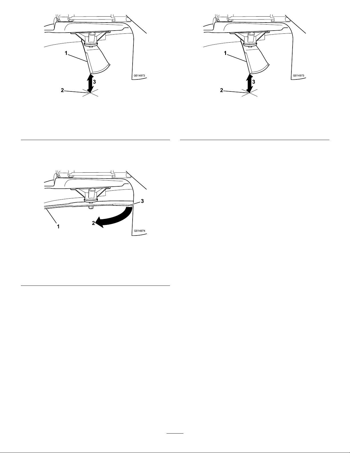
Figure53
g014973
g014973
Figure55
1.Blade(inpositionformeasuring)
2.Levelsurface
3.Measureddistancebetweenbladeandthesurface(A)
4.Rotatethesameblade180degreessothat
theopposingcuttingedgeisnowinthesame
position(Figure54).
Figure54
1.Blade(sidepreviouslymeasured)
2.Measurement(positionusedpreviously)
3.Opposingsideofbladebeingmovedintomeasurement
position
1.Oppositebladeedge(inpositionformeasuring)
2.Levelsurface
3.Secondmeasureddistancebetweenbladeandsurface(B)
A.IfthedifferencebetweenAandBisgreater
than3mm(1/8inch),replacethebladewith
anewblade;refertoRemovingtheBlades
(page40)andInstallingtheBlades(page
40).
Note:Ifabentbladeisreplacedwitha
newblade,andthedimensionobtained
continuestoexceed3mm(1/8inch),the
bladespindlecouldbebent.Contactan
AuthorizedServiceDealerforservice.
B.Ifthevarianceiswithinconstraints,moveto
thenextblade.
g014974
6.Repeatthisprocedureoneachblade.
5.Measurefromthetipofthebladetotheat
surface(Figure55).
Note:Thevarianceshouldbenomorethan
3mm(1/8inch).
39

RemovingtheBlades
Replacethebladesiftheyhitasolidobject,orifthe
bladeisoutofbalanceorbent.
1.Holdthebladeendusingaragorthicklypadded
glove.
2.Removethebladebolt,curvedwasher,and
bladefromthespindleshaft(Figure56).
g000553
Figure58
1.Blade2.Balancer
3.Repeatthisprocedureuntilthebladeis
balanced.
InstallingtheBlades
1.Installthebladeontothespindleshaft(Figure
56).
Important:Thecurvedpartoftheblade
mustbepointingupwardtowardtheinside
ofthemowertoensurepropercutting.
2.Installthecurvedwasher(cuppedsidetoward
theblade)andthebladebolt(Figure56).
3.T orquethebladeboltto135to150N∙m(100
to110ft-lb).
Figure56
1.Sailareaoftheblade3.Curvedwasher
2.Blade4.Bladebolt
SharpeningtheBlades
1.Usealetosharpenthecuttingedgeatboth
endsoftheblade(Figure57).
Note:Maintaintheoriginalangle.
Note:Thebladeretainsitsbalanceifthesame
amountofmaterialisremovedfrombothcutting
edges.
Figure57
1.Sharpenatoriginalangle.
g010341
g004536
Figure59
1.Sailareaoftheblade3.Curvedwasher
2.Blade4.Bladebolt
g000552
2.Checkthebalanceofthebladebyputtingitona
bladebalancer(Figure58).
Note:Ifthebladestaysinahorizontalposition,
thebladeisbalancedandcanbeused.
Note:Ifthebladeisnotbalanced,lesome
metalofftheendofthesailareaonly(Figure57).
40
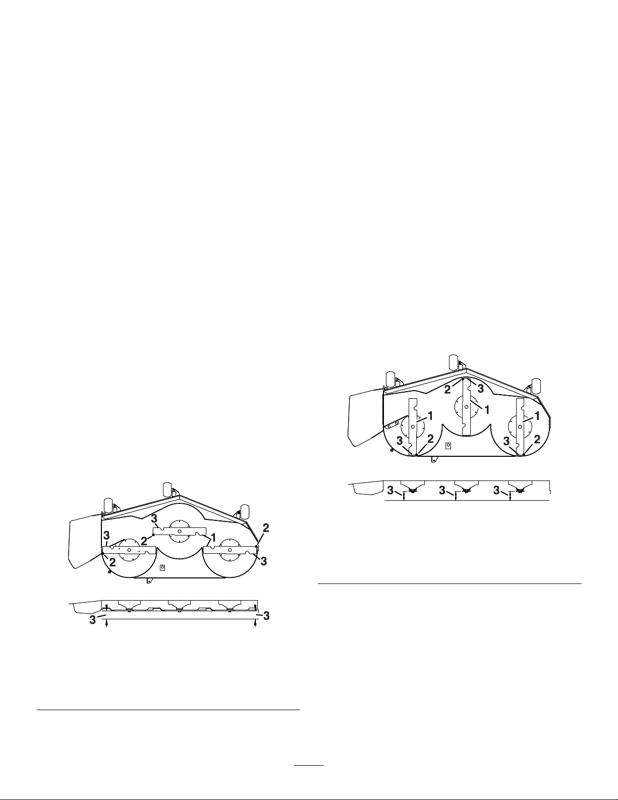
LevelingtheMowerDeck
Checktoensurethatthemowerdeckislevelanytime
youinstallthemowerorwhenyouseeanunevencut
onyourlawn.
Checkthemowerdeckforbentbladespriorto
leveling,andremoveandreplaceanybentblades;
refertoCheckingforBentBlades(page38)before
continuing.
Levelthemowerdeckside-to-siderst;thenyoucan
adjustthefront-to-rearslope.
Requirements:
•Themachinemustbeonalevelsurface.
•Alltiresmustbeproperlyinated;refertoChecking
theTirePressure(page36).
CheckingtheSide-to-SideLevel
1.Parkthemachineonalevelsurface,disengage
theblade-controlswitch(PTO),andengagethe
parkingbrake.
2.Shutofftheengine,removethekey ,andwait
forallmovingpartstostopbeforeleavingthe
operatingposition.
CheckingtheFront-to-RearBlade
Slope
Checkthefront-to-rearbladelevelanytimeyouinstall
themower.Ifthefrontofthemowerismorethan
7.9mm(5/16inch)lowerthantherearofthemower,
adjustthebladelevel.
1.Parkthemachineonalevelsurface,disengage
theblade-controlswitch(PTO),andengagethe
parkingbrake.
2.Shutofftheengine,removethekey ,andwait
forallmovingpartstostopbeforeleavingthe
operatingposition.
3.Settheheightofcutto76mm(3inches).
4.Carefullyrotatethebladessotheyarefacing
fronttorear(Figure61).
5.Measurefromthetipofthefrontbladetothe
atsurfaceandthetipoftherearbladetothe
atsurface(Figure61).
Note:Ifthefrontbladetipisnot1.6to7.9mm
(1/16to5/16inch)lowerthantherearbladetip,
continuetotheLevelingtheMowerDeck(page
42)procedure.
3.Settheheightofcutto76mm(3inches).
4.Carefullyrotatethebladessidetoside.
5.Measurebetweentheoutsidecuttingedgesand
theatsurface(Figure60).
Note:Ifbothmeasurementsarenotwithin5
mm(3/16inch),anadjustmentisrequired;refer
toLevelingtheMowerDeck(page41).
Figure60
1.Bladessidetoside
2.Outsidecuttingedges
3.Measurefromthetipofthe
bladetotheatsurface
here.
g229304
Figure61
1.Bladesfronttorear3.Measurefromthetipofthe
bladetotheatsurface
here.
2.Outsidecuttingedges
g229303
41

LevelingtheMowerDeck
1.Settheanti-scalprollerstothetopholesor
removethemcompletelyforthisprocedure;refer
toAdjustingtheAnti-ScalpRollers(page23).
2.Settheheight-of-cutlevertothe76mm(3inch)
position;refertoAdjustingtheHeightofCut
(page22).
3.Place2blocks,eachhavingathicknessof6.6
cm(2-5/8inches),undereachsideofthefront
edgeofthedeckbutnotundertheanti-scalp
rollerbrackets(Figure62).
4.Place2blocks,eachhavingathicknessof7.3
cm(2-7/8inches),undertherearedgeofthe
cuttingdeckskirt,1oneachsideofthecutting
deck(Figure62).
g297515
Figure63
Figure62
1.Woodblock—6.6cm
(2-5/8inches)thick
2.Woodblock—7.3cm
(2-7/8inches)thick
3.Frontedge
5.Loosentheadjustmentboltsonall4cornersso
thatthedeckissittingsecurelyonall4blocks
(Figure63).
1.Deck-liftarm
2.Chain
3.Hook
4.Adjustmentbolt
6.Ensurethatthereistensiononall4chains
(Figure63).
7.Tightenthe4adjustmentbolts(Figure63).
8.Ensurethattheblockstsnuglyunderthedeck
skirtandthatallboltsaretight.
g297501
9.Verifythatthedeckislevelbycheckingthe
side-to-sidelevelandfront-to-rearbladeslope;
repeatthedecklevelingprocedureifnecessary.
42
RemovingtheMowerDeck
1.Parkthemachineonalevelsurface,disengage
theblade-controlswitch(PTO),andengagethe
parkingbrake.
2.Shutofftheengine,removethekey ,and
disconnectthespark-plugwiresfromthespark
plugs.
3.Lowerthemowertothe76mm(3inches)
height-of-cutposition.
4.Removethemowerbeltfromtheenginepulley;
refertoReplacingtheMowerBelt(page37).
5.Removethehairpincotterandwashersecuring
thelinkpintotheframeanddeck,andremove
thelinkbar(Figure64).
g297515
Figure65
Figure64
1.Linkpin3.Hairpincotter
2.Washer
6.Liftupthemowerdecktorelievetensionfrom
themowerdeck.
7.Removethechainsfromthehooksonthe
deck-liftarms(Figure65).
1.Deck-liftarm
2.Chain
3.Hook
4.Adjustmentbolt
8.Raisetheheightofcuttothetransportposition.
9.Removethebeltfromtheclutchpulleyonthe
engine.
10.Slidethemoweroutfromunderneaththe
machine.
g297517
Note:Retainallpartsforfutureinstallation.
InstallingtheMowerDeck
1.Parkthemachineonalevelsurface,disengage
theblade-controlswitch(PTO),andengagethe
parkingbrake.
2.Shutofftheengine,removethekey ,and
disconnectthespark-plugwiresfromthespark
plugs.
3.Slidethemowerunderthemachine.
4.Lowertheheight-of-cutlevertothelowest
position.
5.Placetheheight-of-cutpininthelockposition
forlowestheightofcut.
6.Lifttherearofthemowerdeckandattachthe
chainstotherearliftarms(Figure65).
7.Attachthefrontchainstothefrontliftarms
(Figure65).
8.Installthelonglinkbarthroughtheframehanger
anddeck.
9.Securethelinkpinwiththehairpincottersand
washersremovedpreviously(Figure64).
10.Installthemowerbeltontotheenginepulley;
refertoReplacingtheMowerBelt(page37).
43

ReplacingtheGrass
Deector
ServiceInterval:Beforeeachuseordaily—Inspect
thegrassdeectorfordamage.
WARNING
Anuncovereddischargeopeningcouldallow
themachinetothrowobjectstowardyouor
bystanders,resultinginseriousinjury.Also,
contactwiththebladecouldoccur.
Neveroperatethemachineunlessyouinstall
amulchplate,dischargedeector,orgrass
collectionsystem.
1.Disengagethespringfromthenotchinthe
deectorbracketandslidetherodoutofthe
weldeddeckbrackets,spring,anddischarge
deector(Figure66).
3.Positionthenewdischargedeectorwiththe
bracketendsbetweentheweldedbracketson
thedeckasshowninFigure67.
4.Installthespringontothestraightendoftherod.
5.PositionthespringontherodasshowninFigure
67sothattheshorterspringendcomesfrom
undertherodbeforethebendandgoingover
therodasitreturnsfromthebend.
6.Lifttheloopendofthespringandplaceitinto
thenotchonthedeectorbracket(Figure67).
Figure66
1.Rod4.Deckbrackets
2.Spring5.Springinstalledoverthe
rod
3.Deector
2.Removethedamagedorworndischarge
deector.
g316724
Figure67
1.Rodandspringassembly
installed
2.Loopendofthespring
installedintothenotchin
thedeectorbracket
3.Rod,shortend,moved
behindthemowerbracket
4.Shortend,retainedby
mowerbracket.
7.Securetherodandspringassemblybytwisting
itsothattheshortendoftherodisbehindthe
frontbracketweldedtothedeck(Figure67).
Important:Thegrassdeectormustbe
springloadedinthedownposition.Liftthe
g297555
deectoruptotestthatitsnapstothefull
downposition.
44

Cleaning
Storage
DisposingofWaste
Engineoil,batteries,hydraulicuid,andengine
coolantarepollutantstotheenvironment.Disposeof
theseaccordingtoyourstateandlocalregulations.
StorageSafety
•Shutofftheengine,removethekey,andwait
forallmovingpartstostopbeforeyouleavethe
operator’sposition.Allowthemachinetocool
beforeadjusting,servicing,cleaning,orstoringit.
•Donotstorethemachineorfuelnearamesor
drainthefuelindoorsorinsideanenclosedtrailer.
•Donotstorethemachineorfuelcontainerwhere
thereisanopename,spark,orpilotlight,such
asonawaterheateroronotherappliances.
CleaningandStorage
1.Disengagetheblade-controlswitch(PTO),and
engagetheparkingbrake.
2.Shutofftheengine,removethekey ,andwait
forallmovingpartstostopbeforeleavingthe
operatingposition.
3.Removegrassclippings,dirt,andgrimefromthe
externalpartsoftheentiremachine,especially
theengineandhydraulicsystem.Cleandirtand
chafffromtheoutsideoftheenginecylinder
headnsandblowerhousing.
Important:Youcanwashthemachine
withmilddetergentandwater.Donot
pressure-washthemachine.Avoid
excessiveuseofwater,especiallynearthe
controlpanel,engine,hydraulicpumps,and
motors.
4.Checktheparkingbrakeoperation;referto
OperatingtheParkingBrake(page18).
5.Servicetheaircleaner;refertoServicingtheAir
Cleaner(page29).
6.Changethecrankcaseoil;refertoChangingthe
EngineOilandOilFilter(page30).
7.Checkthetirepressure;refertoCheckingthe
TirePressure(page36).
8.Chargethebattery;refertoChargingtheBattery
(page35).
9.Scrapeanyheavybuildupofgrassanddirt
fromtheundersideofthemower,thenwashthe
machinewithagardenhose.
Note:Runthemachinewiththeblade-control
switch(PTO)engagedandtheengineathigh
idlefor2to5minutesafterwashing.
10.Checktheconditionoftheblades;referto
ServicingtheCuttingBlades(page38).
11.Preparethemachineforstoragewhennon-use
occursover30days.Preparethemachinefor
storageasfollows:
45

A.Addfuelstabilizer/conditionertofreshfuel
inthetank.Followmixinginstructionsfrom
thefuelstabilizermanufacturer.Donot
useanalcohol-basedstabilizer(ethanolor
methanol).
B.Runtheenginetodistributeconditionedfuel
throughthefuelsystemfor5minutes.
C.Shutofftheengine,allowittocool,and
drainthefueltank.
D.Starttheengineandrunituntilitshutsoff.
E.Disposeoffuelproperly.Recyclethefuel
accordingtolocalcodes.
Important:Donotstorefuelcontaining
stabilizer/conditionerlongerthan
thedurationrecommendedbythe
fuel-stabilizermanufacturer.
12.Removeandchecktheconditionofthespark
plug(s);refertoServicingtheSparkPlug(page
32).Withthesparkplug(s)removedfromthe
engine,pour30ml(2tablespoons)ofengine
oilintothesparkplughole.Usethestarterto
cranktheengineanddistributetheoilinsidethe
cylinder.Installthesparkplug(s).Donotinstall
thewireonthesparkplug(s).
13.Checkandtightenallbolts,nuts,andscrews.
Repairorreplaceanypartthatisdamaged.
14.Paintallscratchedorbaremetalsurfaces.Paint
isavailablefromyourAuthorizedServiceDealer.
StoringtheBattery
1.Fullychargethebattery.
2.Letthebatteryrestfor24hours,thencheckthe
batteryvoltage.
Note:Ifthebatteryvoltageisbelow12.6V ,
repeatsteps1and2.
3.Disconnectthecablesfromthebattery.
4.Checkthevoltageperiodicallytoensurethatthe
voltageis12.4Vorhigher.
Note:Ifthebatteryvoltageisbelow12.4V ,
repeatsteps1and2.
BatteryStorageTips
•Storethebatteryinacool,dryareainanupright
position.
•Donotstackbatteriesdirectlyontopofeachother,
unlesstheyareincartons.
•Donotstackmorethan3batteries(only2ifthe
batterytypeiscommercial).
•Testawetbatteryevery4to6monthsandcharge
it,ifnecessary.
•Alwaystestandchargethebatterybefore
installation.
15.Storethemachineinaclean,drygarageor
storagearea.Removethekeyfromtheswitch
andkeepitoutofreachofchildrenorother
unauthorizedusers.Coverthemachineto
protectitandkeepitclean.
46

Troubleshooting
Problem
Thefueltankisshowingsignsofcollapsing
orthemachineisfrequentlyshowingsigns
ofrunningoutoffuel.
Theengineoverheats.
Thestarterdoesnotcrank.
Theenginedoesnotstart,startshard,or
failstokeeprunning.
PossibleCauseCorrectiveAction
1.Theair-cleanerpaperelementclogged.
1.Theengineloadisexcessive.1.Reducethegroundspeed.
2.Theoillevelinthecrankcaseislow.2.Addoiltothecrankcase.
3.Thecoolingnsandairpassages
undertheengine-blowerhousingare
plugged.
4.Theaircleanerisdirty.
5.Dirt,water,orstalefuelisinthefuel
system.
1.Theblade-controlswitchisengaged.1.Disengagetheblade-controlswitch.
2.Themotion-controlleversarenotin
theNEUTRAL-LOCKposition.
3.Thebatteryisdead.
4.Theelectricalconnectionsare
corrodedorloose.
5.Afuseisblown.5.Replacethefuse.
6.Arelayorswitchisdamaged.
1.Thefueltankisempty.1.Fillthefueltank.
2.Thechoke(ifapplicable)isnoton.
3.Theaircleanerisdirty.
4.Thespark-plugwire(s)islooseor
disconnected.
5.Thesparkplug(s)ispitted,fouled,or
thegapisincorrect.
6.Thereisdirtinfuellter.6.Replacethefuellter.
7.Dirt,water,orstalefuelisinfuel
system.
8.Thereisincorrectfuelinthefueltank.8.Drainthetankandreplacethefuel
9.Theoillevelinthecrankcaseislow.9.Addoiltothecrankcase.
1.Cleanthepaperelement.
3.Removetheobstructionfromthe
coolingnsandairpassages.
4.Cleanorreplacetheair-cleaner
element.
5.ContactanAuthorizedServiceDealer
2.Movethemotion-controllevers
outwardtotheNEUTRAL-LOCKposition.
3.Chargethebattery.
4.Checktheelectricalconnectionsfor
goodcontact.
6.ContactanAuthorizedServiceDealer.
2.MovethechokelevertotheON
position.
3.Cleanorreplacetheair-cleaner
element.
4.Installthewire(s)onthesparkplug.
5.Installanew,correctlygappedspark
plug(s).
7.ContactanAuthorizedServiceDealer.
withthepropertypeorcontactan
authorizedservicedealer .
Theenginelosespower.
1.Theengineloadisexcessive.1.Reducethegroundspeed.
2.Theaircleanerisdirty.
3.Theoillevelinthecrankcaseislow.3.Addoiltothecrankcase.
4.Thecoolingnsandairpassages
undertheengineblowerhousingare
plugged.
5.Thesparkplug(s)ispitted,fouled,or
thegapisincorrect.
6.Thefuel-tankventisblocked.6.ContactanAuthorizedServiceDealer.
7.Thereisdirtinthefuellter.7.Replacethefuellter.
8.Dirt,water,orstalefuelisinthefuel
system.
9.
Thereisincorrectfuelinthefueltank.
2.Cleantheair-cleanerelement.
4.Removetheobstructionfromthe
coolingnsandairpassages.
5.Installanew,correctlygappedspark
plug(s).
8.
ContactanAuthorizedServiceDealer.
9.
Drainthetankandreplacethefuel
withthepropertypeorcontactan
authorizedservicedealer .
47

Problem
PossibleCauseCorrectiveAction
Themachinedoesnotdrive.
Themachinevibratesabnormally .
Thecuttingheightisuneven.
1.Thebypassvalvesareopen.
2.Thetractionbeltsareworn,loose,or
broken.
3.Thetractionbeltsareoffthepulleys.3.ContactanAuthorizedServiceDealer.
4.Thetransmissionhasfailed.4.ContactanAuthorizedServiceDealer.
1.Thecuttingblade(s)is/arebentor
unbalanced.
2.Theblademountingboltisloose.2.Tightentheblademountingbolt.
3.Theenginemountingboltsareloose.3.Tightentheenginemountingbolts.
4.Theenginepulley ,idlerpulley ,orblade
pulleyisloose.
5.Theenginepulleyisdamaged.
6.Thebladespindleisbent.
7.Themotormountislooseorworn.
1.Theblade(s)isnotsharp.1.Sharpentheblade(s).
2.Acuttingblade(s)is/arebent.2.Installanewcuttingblade(s).
3.Themowerisnotlevel.
4.Ananti-scalproller(ifapplicable)isnot
setcorrectly .
5.Theundersideofthemowerdeckis
dirty.
6.Thetirepressureisincorrect.6.Adjustthetirepressure.
7.Abladespindleisbent.
1.Closethetowvalves.
2.ContactanAuthorizedServiceDealer.
1.Installnewcuttingblade(s).
4.Tightentheappropriatepulley.
5.ContactanAuthorizedServiceDealer.
6.ContactanAuthorizedServiceDealer.
7.ContactanAuthorizedServiceDealer.
3.Levelthemowerfromside-to-sideand
front-to-rear.
4.Adjusttheanti-scalpwheelheight.
5.Cleantheundersideofthemower
deck.
7.ContactanAuthorizedServiceDealer.
Thebladesdonotrotate.
1.Thedrivebeltisworn,looseorbroken.1.Installanewdrivebelt.
2.Thedrivebeltisoffofthepulley .
3.Thepower-takeoff(PTO)switchor
PTOclutchisfaulty.
4.Themowerbeltisworn,loose,or
broken.
2.Installthedrivebeltandcheckthe
adjustingshaftsandbeltguidesforthe
correctposition.
3.ContactanAuthorizedServiceDealer.
4.Installanewmowerbelt.
48

Schematics
ElectricalDiagram(Rev .A)
49
g297640

Notes:

Notes:

 Loading...