

Page 1

LCE Products
Toro Z Master G3
3000/5000/6000 Series
Service Manual
Page 2

ABOUT THIS MANUAL
This service manual was written expressly for Toro service technicians. The Toro Company has made every effort to
make the information in this manual complete and correct.
Basic shop safely knowledge and mechanical/electrical skills are assumed. The Table of Contents lists the systems
and the related topics covered in this manual.
The following service materials are available in addition to this service manual:
Hydrostatic Transmissions: Parker UHT Series HB Hydrostatic Transmission Service Manual (HY13-1512-M2/US)
Wheel Motors: Parker/Ross Wheel Motor Service Manual (HY13-1512-006-M1/US 3/07)
Engine: Engine service manuals (available through Kohler and Kawasaki)
Hydraulic Troubleshooting: Interactive Hydraulic Systems Troubleshooting DVD - Toro Part #492-4777
Electrical Troubleshooting: Interactive Electrical Troubleshooting DVD - Toro Part #492-9193
The Z Master G3, 3000, 5000, and 6000, model years 2009 to 2012, are covered in this manual.
The hydrostatic drive system is precision machinery. Maintain strict cleanliness control during all stages of service
and repair. Cover or cap all hose ends and ttings whenever they are exposed. Even a small amount of dirt or other
contamination can severely damage the system.
We are hopeful that you will nd this manual a valuable addition to your service shop. If you have any questions or
comments regarding this manual, please contact us at the following address:
The Toro Company
RLC Service Training Department
8111 Lyndale Avenue South
Bloomington, MN 55420
The Toro Company reserves the right to change product specications or this manual without notice.
Copyright© All Rights Reserved
©2012 The Toro Company
Page 3

ABOUT THIS MANUAL
THIS PAGE INTENTIONALLY LEFT BLANK.
Page 4

TABLE OF CONTENTS
1 - Safety Information
General Information .........................................................................................................................................1-1
Think Safety First.............................................................................................................................................1-1
2 - Specications
Torque Specications ......................................................................................................................................2-1
Standard Torque for Dry, Zinc Plated & Steel Fasteners (Inch Series) ...........................................................2-2
Standard Torque for Dry, Zinc & Steel Fasteners (Metric Fasteners) ..............................................................2-3
Other Torque Specications ............................................................................................................................2-4
Equivalents & Conversions..............................................................................................................................2-5
Decimal & Millimeter Equivalents ..............................................................................................................2-5
U.S. to Metric Conversions .......................................................................................................................2-6
G3 3000/5000/6000 Series Specications ......................................................................................................2-7
G3 3000/5000/6000 Series Specications cont...............................................................................................2-8
G3 3000/5000/6000 Series Specications cont...............................................................................................2-9
Dimensions ....................................................................................................................................................2-10
Commercial 3000 Series .........................................................................................................................2-10
G3/Professional 5000 Series ..................................................................................................................2-10
Dimensions .................................................................................................................................................... 2-11
G3/Professional 6000 Series .................................................................................................................. 2-11
Dimensions ....................................................................................................................................................2-12
G3/Professional 6000 Series cont. .........................................................................................................2-12
3 - Chassis
Caster Fork Assembly Replacement ...............................................................................................................3-1
Caster Fork Assembly Removal ................................................................................................................3-1
Caster Bearing Replacement ..........................................................................................................................3-2
Caster Fork Assembly Installation .............................................................................................................3-4
Front Wheel Bearing Replacement .................................................................................................................3-5
Front Wheel Bearing Removal ..................................................................................................................3-5
Front Wheel Bearing Installation ...............................................................................................................3-7
Fuel Tank Replacement ...................................................................................................................................3-9
Fuel Tank Removal ...................................................................................................................................3-9
Fuel Tank Installation ..............................................................................................................................3-12
Throttle Control Assembly Replacement (Kohler EFI Engine).......................................................................3-14
Throttle Control Assembly Removal ........................................................................................................3-14
Throttle Control Assembly Installation .....................................................................................................3-16
Park Brake Handle Assembly Replacement (2012 & Later) ..........................................................................3-18
Park Brake Handle Removal (2012 & Later) ...........................................................................................3-18
Park Brake Handle Installation (2012 & Later) ........................................................................................3-20
Park Brake Cable Replacement (2011 & Prior) .............................................................................................3-21
Left Park Brake Cable Removal (2011 & Prior).......................................................................................3-21
Left Park Brake Cable Installation (2011 & Prior)....................................................................................3-24
Right Park Brake Cable Removal (2011 & Prior) ....................................................................................3-27
Right Park Brake Cable Installation (2011 & Prior) .................................................................................3-29
Adjusting the Parking Brake ..........................................................................................................................3-32
Park Brake Cable Replacement (2012 & Later) ............................................................................................3-34
Left Park Brake Cable Removal (2012 & Later) ......................................................................................3-34
Left Park Brake Cable Installation (2012 & Later) ...................................................................................3-37
Right Park Brake Cable Removal (2012 & Later) ...................................................................................3-41
Right Park Brake Cable Installation (2012 & Later) ................................................................................3-44
iToro Z Master G3 3000/5000/6000 Series Service Manual
Page 5

TABLE OF CONTENTS
3 - Chassis cont.
Brake Caliper Replacement...........................................................................................................................3-47
Brake Caliper Removal ...........................................................................................................................3-47
Brake Caliper Installation ........................................................................................................................3-49
Motion Control Damper Replacement ...........................................................................................................3-51
Motion Control Damper Removal ............................................................................................................3-51
Motion Control Damper Installation .........................................................................................................3-52
Adjusting the Motion Control Damper............................................................................................................3-52
Adjusting the Motion Control Neutral Lock Pivot ...........................................................................................3-53
Adjusting the Control Handle Position ...........................................................................................................3-53
Motion Control Assembly Replacement.........................................................................................................3-54
Motion Control Assembly Removal .........................................................................................................3-54
Motion Control Assembly Installation ......................................................................................................3-58
4 - Engine
Engine Replacement .......................................................................................................................................4-1
Engine Removal ........................................................................................................................................4-1
Engine Installation .....................................................................................................................................4-7
5 - Hydraulic System
Hydrostatic Pump Removal .............................................................................................................................5-1
G3 UHT Transmission Replacement (2009 through 2011 models) .................................................................5-1
G3 UHT Transmission Removal (2009 - 2011 models) .............................................................................5-1
G3 UHT Transmission Installation (2009 - 2011 models) ..........................................................................5-9
Burnishing the Brake .....................................................................................................................................5-20
UHT Transmission Replacement (2012 & later models) ...............................................................................5-23
UHT Transmission Removal (2012 & later models) ................................................................................5-23
UHT Transmission Installation (2012 & later models) .............................................................................5-28
Wheel Hub Slotted Nut Installation .........................................................................................................5-32
Adjusting the Motion Control Linkage (Neutral Adjustment) ..........................................................................5-34
Checking the Hydraulic Oil ............................................................................................................................5-36
Flow Test Instructions ....................................................................................................................................5-37
Hydraulic Pump Drive Belt Replacement ......................................................................................................5-40
Using the Drive Wheel Release Valves .........................................................................................................5-41
6 - Mower Decks
Mower Belt Replacement ................................................................................................................................6-1
Mower Belt Removal .................................................................................................................................6-1
Mower Belt Installation ..............................................................................................................................6-2
Mower Deck Replacement ..............................................................................................................................6-3
Mower Deck Removal ...............................................................................................................................6-3
Mower Deck Installation ............................................................................................................................6-6
Extension Spring Adjustment (2010 - 2012 Models) .......................................................................................6-6
Mower Spindle Replacement...........................................................................................................................6-7
Mower Spindle Removal (2009 Model G3 Series Units) ...........................................................................6-7
Mower Spindle Installation (2009 Model G3 Series Units) ........................................................................6-8
Mower Spindle Disassembly (2009 Model G3 Series Units) ...........................................................................6-9
Mower Spindle Assembly (2009 Model G3 Series Units) ..............................................................................6-12
Mower Spindle Replacement (2010 & Later Model G3, 3000/5000/6000 Series Units) ...............................6-16
Mower Spindle Removal (2010 & Later Model G3, 3000/5000/6000 Series Units) ................................6-16
Mower Spindle Installation (2010 & Later Model G3, 3000/5000/6000 Series Units) .............................6-17
ii Toro Z Master G3 3000/5000/6000 Series Service Manual
Page 6

TABLE OF CONTENTS
6 - Mower Decks cont.
Mower Spindle Disassembly (2010 & Later Model G3, 3000/5000/6000 Series Units) ................................6-18
Mower Spindle Assembly (2010 & Later Model G3, 3000/5000/6000 Series Units) .....................................6-20
Leveling the Mower Deck ..............................................................................................................................6-23
Deck Leveling .........................................................................................................................................6-23
Servicing the Cutting Blades .........................................................................................................................6-27
Before Inspecting or Servicing the Blades ..............................................................................................6-27
Inspecting the Blades ..............................................................................................................................6-28
Checking for Bent Blades .......................................................................................................................6-28
Removing the Blades ..............................................................................................................................6-29
Sharpening the Blades ............................................................................................................................6-30
Installing the Blades ................................................................................................................................6-30
Electric PTO Clutch Replacement .................................................................................................................6-31
Electric PTO Clutch Removal..................................................................................................................6-31
Electric PTO Clutch Installation...............................................................................................................6-32
Using the Clutch Shim ...................................................................................................................................6-33
Removing the Clutch Shim .....................................................................................................................6-33
Safety Check ...........................................................................................................................................6-35
7 - Electrical
General ............................................................................................................................................................7-1
Relay ...............................................................................................................................................................7-1
Purpose .....................................................................................................................................................7-1
Location ....................................................................................................................................................7-1
How It Works .............................................................................................................................................7-1
Testing .......................................................................................................................................................7-2
PTO Switch ......................................................................................................................................................7-3
Purpose .....................................................................................................................................................7-3
Location ....................................................................................................................................................7-3
How It Works .............................................................................................................................................7-3
Testing .......................................................................................................................................................7-3
Ignition Switch .................................................................................................................................................7-5
Purpose .....................................................................................................................................................7-5
Location ....................................................................................................................................................7-5
How It Works .............................................................................................................................................7-5
Testing .......................................................................................................................................................7-5
Park Brake Switch ...........................................................................................................................................7-6
Purpose .....................................................................................................................................................7-6
Location ....................................................................................................................................................7-6
How It Works .............................................................................................................................................7-6
Testing .......................................................................................................................................................7-6
Seat Switch......................................................................................................................................................7-7
Purpose .....................................................................................................................................................7-7
Location ....................................................................................................................................................7-7
How It Works .............................................................................................................................................7-7
Testing .......................................................................................................................................................7-7
Neutral Safety Switch ......................................................................................................................................7-8
Purpose .....................................................................................................................................................7-8
Location ....................................................................................................................................................7-8
How It Works .............................................................................................................................................7-8
Testing .......................................................................................................................................................7-8
iiiToro Z Master G3 3000/5000/6000 Series Service Manual
Page 7

TABLE OF CONTENTS
7 - Electrical cont.
TVS Diode .......................................................................................................................................................7-9
Purpose .....................................................................................................................................................7-9
Location ....................................................................................................................................................7-9
How It Works .............................................................................................................................................7-9
Testing .......................................................................................................................................................7-9
Fuel Sender ...................................................................................................................................................7-10
Purpose ...................................................................................................................................................7-10
Location ..................................................................................................................................................7-10
How It Works ...........................................................................................................................................7-10
Testing .....................................................................................................................................................7-10
Fuel/Hour Meter............................................................................................................................................. 7-11
Purpose ................................................................................................................................................... 7-11
Location ..................................................................................................................................................7-11
How It Works ........................................................................................................................................... 7-11
Testing ..................................................................................................................................................... 7-11
Electric PTO Clutch .......................................................................................................................................7-12
Purpose ...................................................................................................................................................7-12
Location ..................................................................................................................................................7-12
How It Works ...........................................................................................................................................7-12
Testing .....................................................................................................................................................7-12
Coil Resistance Measurement ................................................................................................................7-12
Measuring Clutch Current Draw ..............................................................................................................7-13
iv Toro Z Master G3 3000/5000/6000 Series Service Manual
Page 8

General Information
SAFETY INFORMATION
This symbol means WARNING or
PERSONAL SAFETY INSTRUCTION read the instruction because it has to do
with your safety. Failure to comply with the
!
This manual is intended as a service and repair manual
only. The safety instructions provided herein are for
troubleshooting, service, and repair of the G3 3000/
5000/6000 Series Mower. The G3 3000/5000/6000
instruction may result in personal injury or
even death.
Think Safety First
Avoid unexpected starting of engine...
Always turn off the engine and disconnect the spark plug
wire(s) before cleaning, adjusting, or repair.
Avoid lacerations and amputations...
Stay clear of all moving parts whenever the engine is
running. Treat all normally moving parts as if they were
moving whenever the engine is running or has the
potential to start.
Series mower and attachment operator’s manuals
contain safety information and operating tips for safe
operating practices. Operator’s manuals are available
through your Toro parts source or:
The Toro Company
Publications Department
8111 Lyndale Avenue South
Bloomington, MN 55420
Avoid injury from batteries...
Battery acid is poisonous and can cause burns. Avoid
contact with skin, eyes, and clothing. Battery gases can
explode. Keep cigarettes, sparks, and ames away from
the battery.
Avoid injury due to inferior parts...
Use only original equipment parts to ensure that
important safety criteria are met.
1
Avoid burns...
Do not touch the engine, mufer, or other components
which may increase in temperature during operation,
while the unit is running or shortly after it has been
running.
Avoid res and explosions...
Avoid spilling fuel and never smoke while working with
any type of fuel or lubricant. Wipe up any spilled fuel
or oil immediately. Never remove the fuel cap or add
fuel when the engine is running. Always use approved,
labeled containers for storing or transporting fuel and
lubricants.
Avoid asphyxiation...
Never operate an engine in a conned area without
proper ventilation.
Avoid injury to bystanders...
Always clear the area of bystanders before starting or
testing powered equipment.
Avoid injury due to projectiles...
Always clear the area of sticks, rocks, or any other
debris that could be picked up and thrown by the
powered equipment.
Avoid modications...
Never alter or modify any part unless it is a factory
approved procedure.
Avoid unsafe operation...
Always test the safety interlock system after making
adjustments or repairs on the machine. Refer to the
Electrical section in this manual for more information.
1-1Toro Z Master G3 3000/5000/6000 Series Service Manual
Page 9

1
SAFETY INFORMATION
THIS PAGE INTENTIONALLY LEFT BLANK.
1-2 Toro Z Master G3 3000/5000/6000 Series Service Manual
Page 10
SPECIFICATIONS
Torque Specications
Recommended fastener torque values are listed in the
following tables. For critical applications, as determined
by Toro, either the recommended torque or a torque
that is unique to the application is clearly identied and
specied in the service manual.
These torque specications for the installation and
tightening of fasteners shall apply to all fasteners
which do not have a specic requirement identied
in the service manual. The following factors shall be
consid ered when applying torque: cleanliness of the
fastener, use of a thread sealant (e.g. Loctite®), degree
of lubrication on the fastener, presence of a prevailing
torque feature, hardness of the surface underneath of
the fastener’s head, or similar condition which affects the
installation.
As noted in the following tables, torque values should
be reduced by 25% for lubricated fasteners to achieve
the similar stress as a dry fastener. Torque values may
also have to be reduced when the fastener is threaded
into aluminum or brass. The specic torque value should
be determined based on the aluminum or brass material
strength, fastener size, length of thread engagement,
etc.
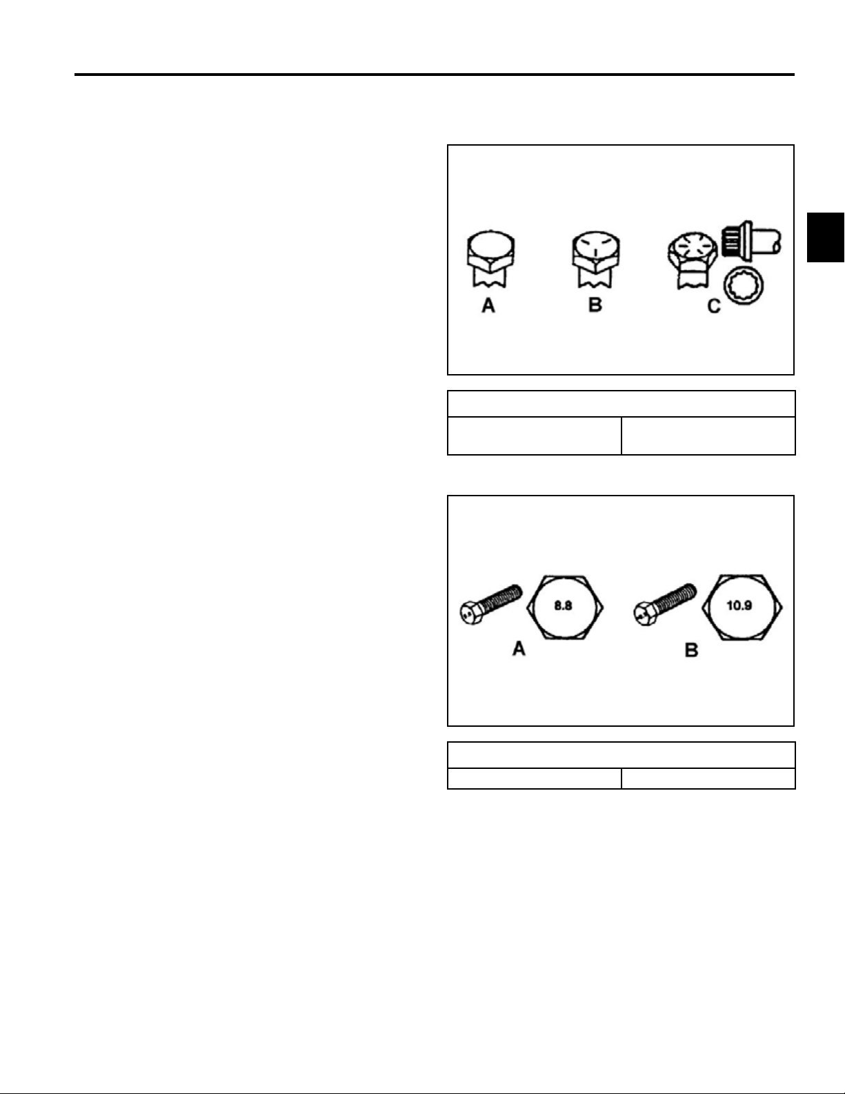
Fastener Identication
Inch Series bolts and Screws
(A) Grade 1 & 2
(B) Grade 5
2
(C) Grade 8
The standard method of verifying torque shall be performed by marking a line on the fastener (head or nut)
and mating part, then back off fastener 1/4 of a turn.
Measure the torque required to tighten the fastener until
the lines match up.
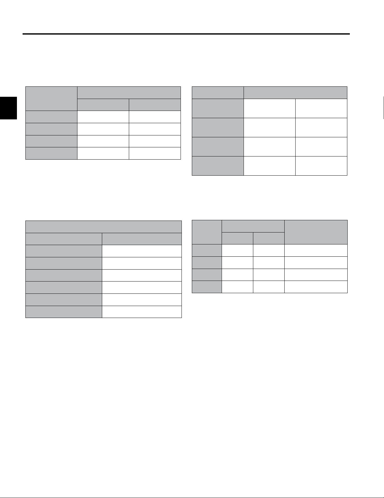
Metric Bolts and Screws
(A) Class 8.8 (B) Class 10.9
2-1Toro Z Master G3 3000/5000/6000 Series Service Manual
Page 11

SPECIFICATIONS
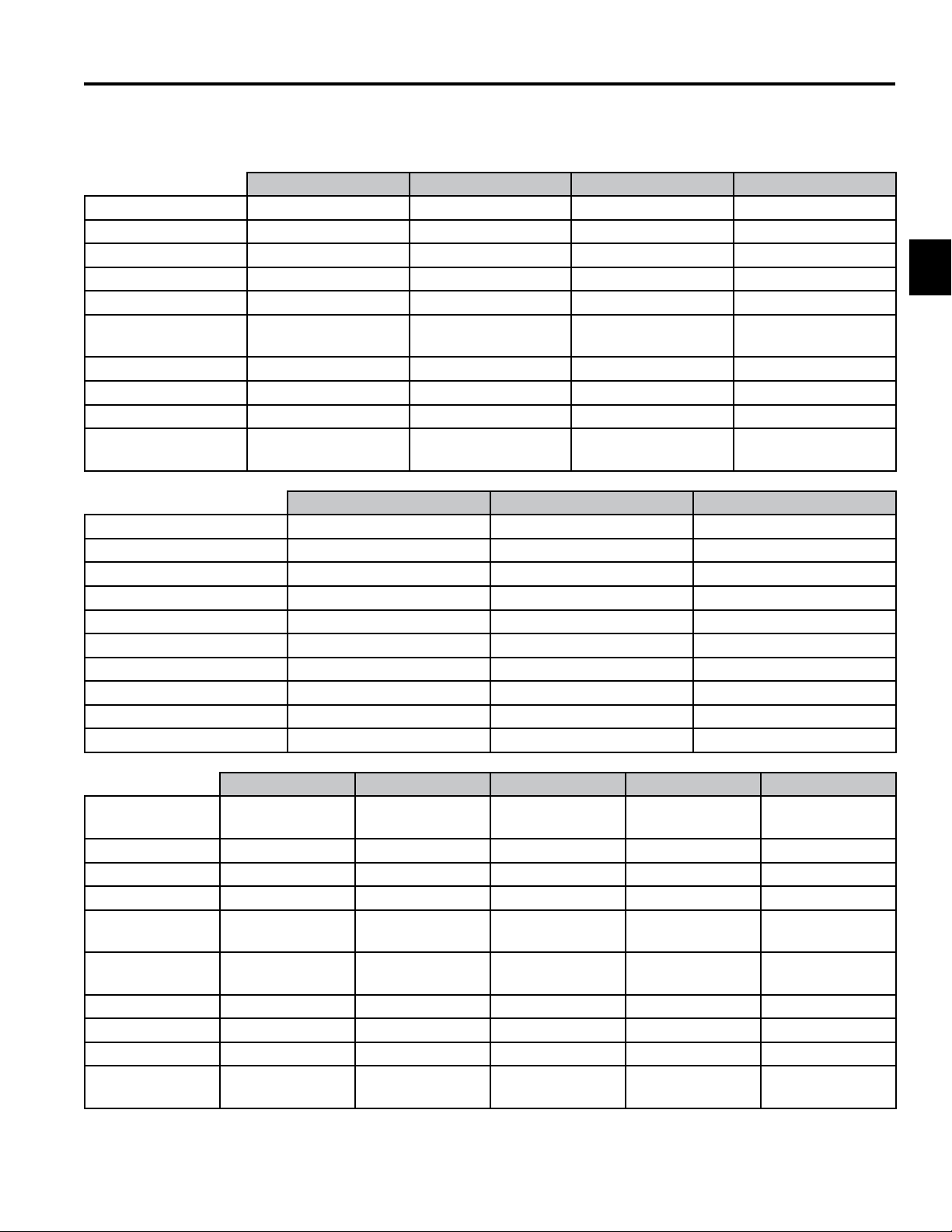
Standard Torque for Dry, Zinc Plated, and Steel Fasteners (Inch Series)
Standard Torque for Dry, Zinc Plated & Steel Fasteners (Inch Series)
Grade 1, 5, &
Thread Size
2
# 6 - 32 UNC
# 6 - 40 UNF 17 ± 2 190 ± 20 25 ± 2 280 ± 20
# 8 - 32 UNC
# 8 - 36 UNF 31 ± 3 350 ± 30 43 ± 4 31 ± 3
# 10 - 24 UNC
#10 - 32 UNF 48 ± 4 540 ± 45 68 ± 6 765 ± 70
1/4 - 20 UNC 48 ± 7 53 ± 7 599 ± 79 100 ± 10 1125 ± 100 140 ± 15 1580 ± 170
1/4 - 28 UNF 53 ± 7 65 ± 10 734 ± 113 115 ± 10 1300 ± 100 160 ± 15 1800 ± 170
5/16 - 18 UNC 115 ± 15 105 ± 15 1186 ± 169 200 ± 25 2250 ± 280 300 ± 30 3390 ± 340
5/16 - 24 UNF 138 ± 17 128 ± 17 1446 ± 192 225 ± 25 2540 ± 280 325 ± 30 3670 ± 340
3/8 - 16 UNC 16 ± 2 16 ± 2 22 ± 3 30 ± 3 41 ± 4 43 ± 4 58 ± 5
3/8 - 24 UNF 17 ± 2 18 ± 2 24 ± 3 35 ± 3 47 ± 4 50 ± 4 68 ± 5
7/16 - 14 UNC 27 ± 3 27 ± 3 37 ± 4 50 ± 5 68 ± 7 70 ± 7 68 ± 9
7/16 - 20 UNF 29 ± 3 29 ± 3 39 ± 4 55 ± 5 75 ± 7 77 ± 7 104 ± 9
1/2 - 13 UNC 30 ± 3 48 ± 7 65 ± 9 75 ± 8 102 ± 11 105 ± 10 142 ± 14
1/2 - 20 UNF 32 ± 3 53 ± 7 72 ± 9 85 ± 8 115 ± 11 120 ± 10 163 ± 14
5/8 - 11 UNC 65 ± 10 88 ± 12 119 ± 16 150 ± 15 203 ± 20 210 ± 20 285 ± 27
5/8 - 18 UNF 75 ± 10 95 ± 15 129 ± 20 170 ± 15 230 ± 20 240 ± 20 325 ± 27
3/4 - 10 UNC 93 ± 12 140 ± 20 190 ± 27 265 ± 25 359 ± 34 374 ± 35 508 ± 47
3/4 - 16 UNF 115 ± 15 165 ± 25 224 ± 34 300 ± 25 407 ± 34 420 ± 35 569 ± 47
7/8 - 9 UNC 140 ± 20 225 ± 25 305 ± 34 430 ± 45 583 ± 61 600 ± 60 813 ± 81
7/8 - 14 UNF 155 ± 25 260 ± 30 353 ± 41 475 ± 45 644 ± 61 660 ± 60 895 ± 81
8 with Thin
Height Nuts
In-lb In-lb N-cm In-lb N-cm In-lb N-cm
10 ± 2 13 ± 2 147 ± 23
13 ± 2 25 ± 5 282 ± 30
18 ± 2 30 ± 5 339 ± 56
ft-lb ft-lb N-m ft-lb N-m ft-lb N-m
SAE Grade 1 Bolts, Screws,
Studs, & Sems with Regular
Height Nuts (SAE J995
Grade 2 or Stronger Nuts)
SAE Grade 5 Bolts, Screws,
Studs, & Sems with Regular
Height Nuts (SAE J995
Grade 2 or Stronger Nuts)
15 ± 2 169 ± 23 23 ± 2 260 ± 34
29 ± 3 330 ± 30 41 ± 4 460 ± 45
42 ± 4 475 ± 45 60 ± 6 674 ± 70
SAE Grade 8 Bolts, Screws,
Studs, & Sems with Regular
Height Nuts (SAE J995
Grade 2 or Stronger Nuts)
Note: Reduce torque values listed in the table above
by 25% for lubricated fasteners. Lubricated fasteners
are defined as threads coated with a lubricant such as
oil, graphite, or thread sealant such as Loctite.
Note: The nominal torque values listed above for
Grade 5 and 8 fasteners are based on 75% of the
minimum proof load specified in SAE J429. The
tolerance is approximately ± 10% of the nominal torque
value. Thin height nuts include jam nuts.
Note: Torque values may have to be reduced when
installing fasteners into threaded aluminum or brass.
The specific torque value should be determined based
on the fastener size, the aluminum or base material
strength, length of thread engagement, etc.
2-2 Toro Z Master G3 3000/5000/6000 Series Service Manual
Page 12

SPECIFICATIONS
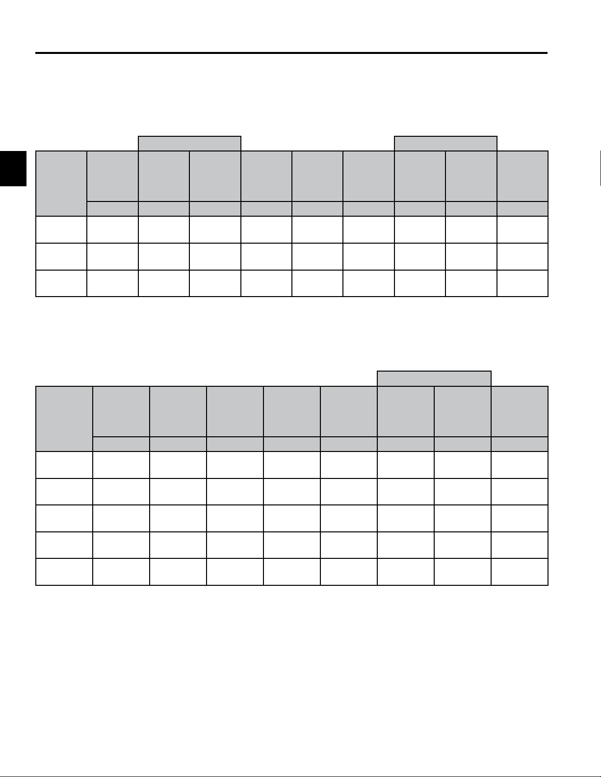
Standard Torque for Dry, Zinc, and Steel Fasteners (Metric Fasteners)
Standard Torque for Dry, Zinc & Steel Fasteners (Metric Fasteners)
Class 8.8 Bolts, Screws, and Studs with
Thread Size
M5 X 0.8 57 ± 5 in-lb 644 ± 68 N-cm 78 ± 8 in-lb 881 ± 90 N-cm
M6 X 1.0 96 ± 10 in-lb 1085 ± 113 N-cm 133 ± 14 in-lb 1503 ± 158 N-cm
M8 X 1.25 19 ± 2 ft-lb 26 ± 3 N-m 28 ± 3 ft-lb 38 ± 4 N-m
M10 X 1.5 38 ± 4 ft-lb 52 ± 5 N-m 54 ± 6 ft-lb 73 ± 8 N-m
M12 X 1.75 66 ± 7 ft-lb 90 ± 10 N-m 93 ± 10 ft-lb 126 ± 14 N-m
M16 X 2.0 166 ± 15 ft-lb 225 ± 23 N-m 229 ± 23 ft-lb 310 ± 31 N-m
M20 X 2.5 325 ± 33 ft-lb 440 ± 45 N-m 450 ± 36 ft-lb 610 ± 62 N-m
Note: Reduce torque values listed in the table above
by 25% for lubricated fasteners. Lubricated fasteners
are defined as threads coated with a lubricant such as
oil, graphite, or thread sealant such as Loctite.
Note: Torque values may have to be reduced when
installing fasteners into threaded aluminum or brass.
The specific torque value should be determined based
on the fastener size, the aluminum or base material
strength, length of thread engagement, etc.
Regular Height Nuts
(Class 8 or Strong Nuts)
Note: The nominal torque values listed above are
based on 75% of the minimum proof load specified in
SAE J1199. The tolerance is approximately ± 10% of
the nominal torque value. Thin height nuts include jam
nuts.
Class 10.9 Bolts, Screws, and Studs with
Regular Height Nuts (
Class 10 or Strong Nuts)
2
2-3Toro Z Master G3 3000/5000/6000 Series Service Manual
Page 13
SPECIFICATIONS
Other Torque Specifications
Other Torque Specications
SAE Grade 8 Steel Set Screws
Recommended Torque
Square Head Hex Socket
2
Thread Size
1/4 - 20 UNC 140 ± 20 in-lb 73 ± 12 in-lb
5/16 - 18 UNC 215 ± 35 in-lb 145 ± 20 in-lb
3/8 - 16 UNC 35 ± 10 ft-lb 18 ± 3 ft-lb
1/2 - 13 UNC 75 ± 15 ft-lb 50 ± 10 ft-lb
Thread Cutting Screws
(Zinc Plated Steel)
Type 1, Type 23, or Type F
Thread Size Baseline Torque*
No. 6 - 32 UNC 20 ± 5 in-lb
Wheel Bolts and Lug Nuts
Thread Size Recommended Torque**
7/16 - 20 UNF
Grade 5
1/2 - 20 UNF
Grade 5
M12 X 1.25
Class 8.8
M12 X 1.5
Class 8.8
** For steel wheels and non-lubricated fasteners.
Thread Cutting Screws
Thread
Size
No. 6 18 20 20 ± 5 in-lb
Threads per Inch
Type A Type B
65 ± 10 ft-lb 88 ± 14 N-m
80 ± 10 ft-lb 108 ± 14 N-m
80 ± 10 ft-lb 108 ± 14 N-m
80 ± 10 ft-lb 108 ± 14 N-m
(Zinc Plated Steel)
Baseline Torque*
No. 8 - 32 UNC 30 ± 5 in-lb
No.10 - 24 UNC 38 ± 7 in-lb
1/4 - 20 UNC 85 ± 15 in-lb
5/16 - 18 UNC 110 ± 20 in-lb
3/8 - 16 UNC 200 ± 100 in-lb
Conversion Factors
in-lb X 11.2985 = N-cm
ft-lb X 1.3558 = N-m
No. 8 15 18 30 ± 5 in-lb
No. 10 12 16 38 ± 7 in-lb
No. 12 11 14 85 ± 15 in-lb
* Hole size, material strength, material thickness and
finish must be considered when determining specific
torque values. All torque values are based on nonlubricated fasteners.
N-cm X - 0.08851 = in-lb
N-cm X 0.73776 = ft-lb
2-4 Toro Z Master G3 3000/5000/6000 Series Service Manual
Page 14

Equivalents & Conversions
Equivalents and Conversions
Decimal and Millimeter Equivalents
Decimal & Millimeter Equivalents
Fractions Decimals mm Fractions Decimals mm
1/64 0.015625 0.397 33/64 0.515625 13.097
1/32 0.03125 0.794 16/32 0.53125 13.484
3/64 0.046875 1.191 35/64 0.546875 13.891
1/16 0.0625 1.588 9/16 0.5625 14.288
5/64 0.078125 1.984 37/64 0.578125 14.684
3/32 0.9375 2.381 19/32 0.59375 15.081
1/8 0.1250 3.175 5/8 0.6250 15.875
5/32 0.15625 3.969 21/32 0.65625 16.669
3/16 0.1875 4.762 11/16 0.6875 17.462
7/32 0.21875 5.556 23/32 0.71875 18.256
1/4 0.2500 6.350 3/4 0.7500 19.050
9/32 0.28125 7.144 25/32 0.78125 19.844
5/16 0.3125 7.541 13/16 0.8125 20.638
11/32 0.34375 8.731 27/32 0.84375 21.431
3/8 0.3750 9.525 7/8 0.8750 22.225
13/32 0.40625 10.319 29/32 0.90625 23.019
7/16 0.4375 11.112 15/16 0.9375 23.812
15/32 0.46875 11.906 31/32 0.96875 24.606
1/2 0.5000 12.700 1 1.000 25.400
9/64 0.140625 3.572 41/64 0.640625 16.272
11/64 0.171875 4.366 43/64 0.671875 17.066
13/64 0.203125 5.159 45/64 0.703125 17.859
15/64 0.234375 5.953 47/64 0.734375 18.653
17/64 0.265625 6.747 49/64 0.765625 19.447
19/64 0.296875 7.541 51/64 0.796875 20.241
21/64 0.328125 8.334 53/64 0.828125 21.034
23/64 0.359375 9.128 55/64 0.859375 21.828
25/64 0.390625 9.922 57/64 0.890625 22.622
27/64 0.421875 10.716 59/64 0.921875 23.416
29/64 0.453125 11.509 61/64 0.953125 24.209
31/64 0.484375 12.303 63/64 0.984375 25.003
1 mm = 0.03937 in. 0.001 in. = 0.0254 mm
SPECIFICATIONS
2
2-5Toro Z Master G3 3000/5000/6000 Series Service Manual
Page 15

2
U.S. to Metric Conversions
SPECIFICATIONS
U.S. to Metric Conversions
To Convert Into Multiply By
Miles
Yards
Linear
Measurement
Area
Volume
Weight
Pressure
Work
Liquid Volume
Liquid Flows
Temperature
Feet
Feet
Inches
Inches
Inches
Square Miles
Square Feet
Square Inches
Acre
Cubic Yards
Cubic Feet
Cubic Inches
Tons (Short)
Pounds
Ounces
Pounds/Sq. In. Kilopascal
Foot-pounds
Foot-pounds
Inch-pounds
Quarts
Gallons
Gallons/Minute Liters/Minute
Fahrenheit Celsius
Kilometers
Meters
Meters
Centimeters
Meters
Centimeters
Millimeters
Square Kilometers
Square Meters
Square Centimeters
Hectare
Cubic Meters
Cubic Meters
Cubic Centimeters
Metric Tons
Kilograms
Grams
Newton-Meters
Kilogram-Meters
Kilogram-Centimeters
Liters
Liters
1.609
0.9144
0.3048
30.48
0.0254
2.54
25.4
2.59
0.0929
6.452
0.4047
0.7646
0.02832
16.39
0.9078
0.4536
28.3495
6.895
1.356
0.1383
1.152144
0.9463
3.785
3.785
1. Subtract 32°
2. Multiply by 5/9
2-6 Toro Z Master G3 3000/5000/6000 Series Service Manual
Page 16
SPECIFICATIONS
G3 3000/5000/6000 Series Specications
Engines: 20.5 hp (15.4kW) 22 hp (16.2 kW) 23.5 hp (17.6kW) 24 hp (17.9 kW)
Make Kawasaki Kawasaki FX Kawasaki Kawasaki FX
Model FX651V FX691V FX730V FX691V
Hi-Idle 3600 ±100 RPM 3600 ± 100 RPM 3600 ±100 RPM 3600 ± 100 RPM
Low-Idle 1550 RPM 1550 RPM 1550 RPM 1800 RPM
Spark Plug NGK BPR4ES NGK BPR4ES NGK BPR4ES NGK BPR4ES
Oil SAE 10w-30 /
SAE10w-40
Oil Capacity 2.2Qt. (2.1 L) 2.2 Qt. (2.1 L) 2.2 Qt. (2.1 L) 2.2 Qt. (2.1 L)
CARB No No 78924 78922 / 78926 78928
EPA Yes Yes Yes Yes
Heavy Duty Air
Canister
Engines: 24.5 hp (18.5 kW) 25.5 hp (19.2 kW) 25.5 hp (19.2 kW)
Make Kawasaki Kawasaki Kawasaki (Propane)
Model FX751V FX801V FX801V
Hi-Idle 3600 ± 100 RPM 3600 ± 100 RPM 3750 ± 50 RPM
Low-Idle 1550 RPM 1550 RPM 1550 RPM
Spark Plug NGK BPR4ES NGK BPR4ES NGK BPR4ES
Oil SAE 10w-30 / SAE10w-40 SAE 10w-30 / SAE10w-40 SAE 10w-30 / SAE10w-40
Oil Capacity 2.2 Qt. (2.1 L) 2.2 Qt. (2.1 L) 1.9 Qt. (1.8 L)
CARB No No No
EPA Yes Yes Yes
Heavy Duty Air Canister Standard Standard Standard
Standard Standard Standard Standard
SAE 10w-30 /
SAE10w-40
SAE 10w-30 /
SAE10w-40
SAE 10w-30 /
SAE10w-40
2
Engines: 23 hp (17.2 kW) 25 hp (18.6 kW) 27 hp (20.1 kW) 29 hp (21.6 kW) 34 hp (25.4 kW)
Make
Model CV680S CV730S CV740S ECV749 FH921V
Hi-Idle 3800 ± 50 RPM 3800 ± 50 RPM 3800 ± 50 RPM 3800 ± 50 RPM 3600 ± 100
Low-Idle 1800 RPM 1800 RPM 1800 RPM 1800 RPM 1550 RPM
Spark Plug Champion
Oil SAE 10w-30 /
Oil Capacity 2.0 Qt. (1.9 L) 2.0 Qt. (1.9 L) 2.0 Qt. (1.9 L) 2.0 Qt. (1.9 L) 1.8 Qt. (1.7 L)
CARB No No No No No
EPA Yes Yes Yes Yes Yes
Heavy Duty Air
Canister
Kohler Command Kohler Command
Champion
R12YC
SAE10w-40
Standard Standard Standard Standard Standard
R12YC
SAE 10w-30 /
SAE10w-40
Kohler Command
Pro
Champion
R12YC
SAE 10w-30 /
SAE10w-40
Kohler EFI Kohler Command
Champion
R12YC
SAE 10w-30 /
SAE10w-40
NGK BPR5ES
SAE 10w-30 /
SAE10w-40
2-7Toro Z Master G3 3000/5000/6000 Series Service Manual
Page 17

SPECIFICATIONS
G3 3000/5000/6000 Series Specications cont.
Fuel System:
Fuel Tank Capacity 8 Gallon (US) (26.5 L) 12 Gallon (US) (45.4 L) 43.5 lb Propane (19.7 kg)
Fuel Gauge Located on top of tank. Located on tank
Fuel Delivery System Fuel pump Vapor draw
2
Traction Drives:
Hydraulic Drive
System
Pump 12cc No Fans 12cc w/Check Valve 12cc w/Shock Valve 16cc w/Shock Valve
Motor 14.6 cir 14.6 cir 14.6 cir 17.1 cir
Hydraulic Fluid Toro Hypr-Oil (500 hr service) or Mobil 1 15w50 Motor Oil (250 hr service)
Hydraulic Fluid
Capacity
Ground Speed 0 to 8 mph fwd 0 to 10 mph fwd 0 to 10 mph fwd 0 to 12 mph fwd
Release Valves External lever on each unit. Allow unit to be moved without engine running
Pump drive Belt tension via spring loaded idler
Mowing Decks: 48” 52” 60” 72”
Cutting Deck Turbo Force Turbo Force Turbo Force Turbo Force
Cutting Height 1.0” to 5.5” (25.4mm - 139.7mm) in .25” (6.3mm) increments
Blade Tip Speed 18500 + ft/min 18500 + ft/min 18500 + ft/min 18500 + ft/min
Spindle
Conguration Tools Adjust or Hand Adjust Bafe
Clutch Models with 29 hp and under utilize a 200 ft-lb clutch.
PTO Idler Spring-loaded idler system
Construction 7 gauge (.179”/ 4.5mm) Steel Welded Construction
Blades 16.5” long, .250”
Standard Greasable
Ball Bearing
thick, 2.5” wide, heat
treated steel blades,
qty 3
52 oz. (1.5 liters) per side w/ lter change
Standard Greasable
Models above 29 hp utilize a 250 ft-lb clutch.
18.0” long, .250”
thick, 2.5” wide, heat
treated steel blades,
Unitized Pump & Motor
Ball Bearing
qty 3
Standard Greasable
Ball Bearing
20.5” long, .250”
thick, 2.5” wide, heat
treated steel blades,
qty 3
Tapered Roller or
Greasable Ball
Bearing
24.5” long, .250”
thick, 2.5” wide, heat
treated steel blades,
qty 3
2-8 Toro Z Master G3 3000/5000/6000 Series Service Manual
Page 18

SPECIFICATIONS
G3 3000/5000/6000 Series Specications cont.
Electrical System:
Voltage 12 volt, negative ground
Battery Type Wet-Battery
Fuses Blade Type
Hourmeter with
Service Indicator
Controls:
Steering Levers Dual, wrap-around, hydraulic dampened, with cushioned grips
Parking Brake Right hand operated lever with cushioned grip
Deck Lift Foot lift assist via foot pedal
Cutting Height Controlled by keyed height of cut pin
Standard Equipment
2
2-9Toro Z Master G3 3000/5000/6000 Series Service Manual
Page 19
2
SPECIFICATIONS
Dimensions
Commercial 3000 Series
Overall Length Overall Height
Model #
74952
74953
74954
Wheel
Base
in./cm in./cm in./cm in./cm in./cm in./cm in./cm in./cm lbs./kg
47.7/
121.2
47.7/
121.2
50.6/
128.5
ROPS
Up
79.2/
201.2
79.2/
201.2
83.1/
211.1
ROPS
Folded
80.9/
205.5
80.9/
205.5
84.8/
215.4
Width
Outside
Tires
45.7/
116.1
45.7/
116.1
53.0/
134.6
Overall
Width
(Chute
Down)
63.6/
161.5
67.6/
171.7
75.7/
192.2
Gate
Width
54.0/
137.2
57.5/
146.1
61.7/
156.8
ROPS
Up
70.5/
179.1
70.5/
179.1
70.5/
179.1
ROPS
Folded
46.8/
118.9
46.8/
118.9
46.8/
118.9
Weight
1120/
508.0
1168/
529.8
1165/
528.0
G3/Professional 5000 Series
Overall Height
Wheel
Model #
74901 47.7/121.2 79.2/201.2 45.7/116.1 63.6/161.5 54.0/137.2 70.5/179.1 46.8/118.9
74903 47.7/121.2 79.2/201.2 45.7/116.1 67.6/171.7 57.5/146.1 70.5/179.1 46.8/118.9
74915 50.6/128.5 83.1/211.1 53.0/134.6 75.7/192.3 61.7/156.7 70.5/179.1 46.8/118.9
74916 53.6/136.1 86.1/218.7 59.1/150.1 87.6/222.5 73.6/186.9 70.5/179.1 46.8/118.9
74930 50.6/128.5 83.1/211.1 53.0/134.6 75.7/192.3 61.7/156.7 70.5/179.1 46.8/118.9
Base
in./cm in./cm in./cm in./cm in./cm in./cm in./cm lbs./kg
Overall
Length
Width
Outside
Tires
Overall
Width
(Chute
Down)
Gate
Width
ROPS Up
Folded
ROPS
Weight
1120/
508.0
1168/
529.8
1216/
551.6
1296/
588.0
1255/
569.0
2-10 Toro Z Master G3 3000/5000/6000 Series Service Manual
Page 20

SPECIFICATIONS
Dimensions
G3/Professional 6000 Series
Overall Height
Wheel
Model #
74922 47.7/121.2 79.2/201.2 45.7/116.1 63.6/161.5 54.0/137.2 70.5/179.1 46.8/118.9
74923 47.7/121.2 79.2/201.2 45.7/116.1 63.6/161.5 54.0/137.2 70.5/179.1 46.8/118.9
74925 50.6/128.5 83.1/211.1 53.0/134.6 75.7/192.3 61.7/156.7 70.5/179.1 46.8/118.9
74926 50.6/128.5 83.1/211.1 53.0/134.6 75.7/192.3 61.7/156.7 70.5/179.1 46.8/118.9
74927 53.6/136.1 86.1/218.7 59.1/150.1 87.6/222.5 73.6/186.9 70.5/179.1 46.8/118.9
74928 53.6/136.1 86.1/218.7 59.1/150.1 87.6/222.5 73.6/186.9 70.5/179.1 46.8/118.9
74935 50.6/128.5 83.1/211.1 53.0/134.6 75.7/192.3 61.7/156.7 70.5/179.1 46.8/118.9
74936 50.6/128.5 83.1/211.1 53.0/134.6 75.7/192.3 61.7/156.7 70.5/179.1 46.8/118.9
74937 53.6/136.1 86.1/218.7 59.1/150.1 87.6/222.5 73.6/186.9 70.5/179.1 46.8/118.9
74938 53.6/136.1 86.1/218.7 59.1/150.1 87.6/222.5 73.6/186.9 70.5/179.1 46.8/118.9
74975 50.6/128.5 83.1/211.1 53.0/134.6 75.7/192.3 61.7/156.7 70.5/179.1 46.8/118.9
74977 53.6/136.1 86.1/218.7 59.1/150.1 87.6/222.5 73.6/186.9 70.5/179.1 46.8/118.9
78922 47.7/121.2 79.2/201.2 45.7/116.1 63.6/161.5 54.0/137.2 70.5/179.1 46.8/118.9
78924 47.7/121.2 79.2/201.2 45.7/116.1 67.6/171.7 57.5/146.1 70.5/179.1 46.8/118.9
78926 50.6/128.5 83.1/211.1 53.0/134.6 75.7/192.3 61.7/156.7 70.5/179.1 46.8/118.9
78928 53.6/136.1 86.1/218.7 59.1/150.1 87.6/222.5 73.6/168.9 70.5/179.1 46.8/118.9
Base
in./cm in./cm in./cm in./cm in./cm in./cm in./cm lbs./kg
Overall
Length
Width
Outside
Tires
Overall
Width
(Chute
Down)
Gate
Width
ROPS Up
Folded
ROPS
Weight
1147/
520.3
1147/
520.3
1254/
568.8
1255/
569.3
1334/
605.1
1350/
612.3
1269/
575.6
1269/
575.6
1349/
611.9
1349/
611.9
1255/
569.3
1352/
613.3
1147/
520.3
1147/
520.3
1255/
569.3
1350/
612.3
2
2-11Toro Z Master G3 3000/5000/6000 Series Service Manual
Page 21

2
SPECIFICATIONS
Dimensions
G3/Professional 6000 Series cont.
Overall Height
Wheel
Model #
74902TE 47.7/121.2 79.2/201.2 45.7/116.1 63.6/161.5 54.0/137.2 70.5/179.1 46.8/118.9
74923TE 47.7/121.2 79.2/201.2 45.7/116.1 63.6/161.5 54.0/137.2 70.5/179.1 46.8/118.9
74925TE 50.6/128.5 83.1/211.1 53.0/134.6 75.7/192.3 61.7/156.7 70.5/179.1 46.8/118.9
74941CP 47.7/121.2 79.2/201.2 45.7/116.1 63.6/161.5 54.0/137.2 70.5/179.1 46.8/118.9
74943CP 47.7/121.2 79.2/201.2 45.7/116.1 67.6/171.7 57.5/146.1 70.5/179.1 46.8/118.9
74945CP 50.6/128.5 83.1/211.1 53.0/134.6 75.7/192.3 61.7/156.7 70.5/179.1 46.8/118.9
74955CP 50.6/128.5 83.1/211.1 53.0/134.6 75.7/192.3 61.7/156.7 70.5/179.1 46.8/118.9
74957CP 53.6/136.1 86.1/218.7 59.1/150.1 87.6/222.5 73.6/186.9 70.5/179.1 46.8/118.9
74960CP 50.6/128.5 83.1/211.1 53.0/134.6 75.7/192.3 61.7/156.7 70.5/179.1 46.8/118.9
74961CP 53.6/136.1 86.1/218.7 59.1/150.1 87.6/222.5 73.6/186.9 70.5/179.1 46.8/118.9
Base
in./cm in./cm in./cm in./cm in./cm in./cm in./cm lbs./kg
Overall
Length
Width
Outside
Tires
Overall
Width
(Chute
Down)
Gate
Width
ROPS Up
ROPS
Folded
Weight
1226/
556.0
1190/
539.8
1301/
590.1
1205/
546.6
1210/
548.8
1254/
568.8
1259/
571.1
1350/
612.3
1269/
575.6
1349/
611.9
2-12 Toro Z Master G3 3000/5000/6000 Series Service Manual
Page 22
CHASSIS
Caster Fork Assembly Replacement
Caster Fork Assembly Removal
1. Raise the front of the machine off the ground,
leaving enough clearance to remove the caster fork
from the frame.
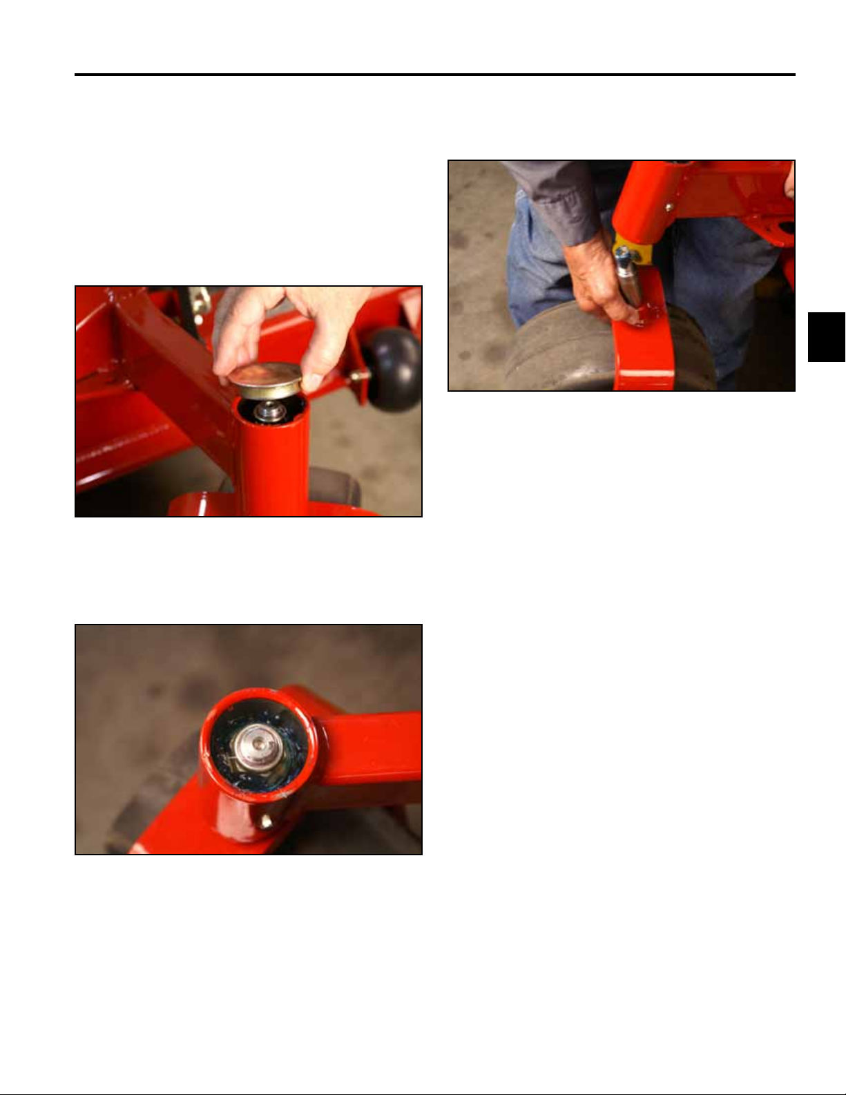
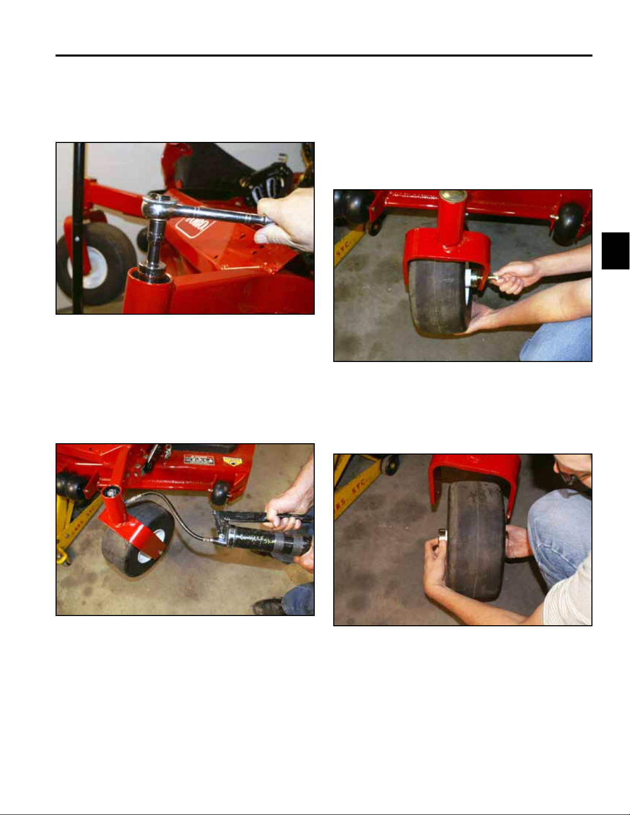
2. Remove the grease cap from the frame (Fig. 001).
4. Slide the caster fork assembly out of the frame (Fig.
003).
3
Fig. 003 PICT-0355
Fig. 001 PICT-0351
3. Remove the locknut (Fig. 002).
Fig. 002 PICT-0352a
3-1Toro Z Master G3 3000/5000/6000 Series Service Manual
Page 23
CHASSIS
3
Caster Bearing Replacement
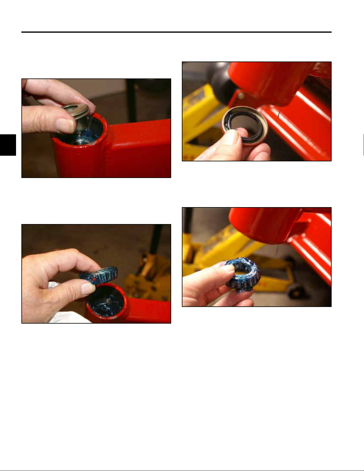
1. Remove the 3 Belleville washers (Fig. 004).
Fig. 004 PICT-0359a
2. Remove the top tapered bearing (Fig. 005).
3. Remove the bottom grease seal (Fig. 006).
Fig. 006 PICT-0364a
4. Remove the bottom tapered bearing (Fig. 007).
Fig. 007 PICT-0365
Fig. 005 PICT-0361a
3-2 Toro Z Master G3 3000/5000/6000 Series Service Manual
Page 24
CHASSIS
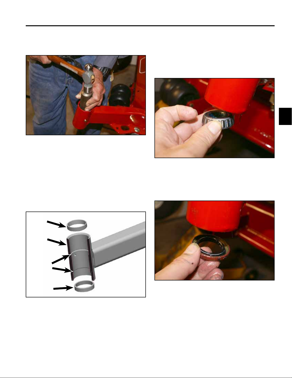
5. Drive the top and bottom tapered bearing cups out of
the caster fork hub (Fig. 008).
Fig. 008 PICT-0367a
6. Install new tapered bearing cups by pressing each
bearing cup into the caster fork hub so that the thicker part of the taper is pressed in rst. The bearing
cups should seat against the shoulder inside the
frame.
7. Pack the upper and lower tapered bearings with
grease (No. 2 general purpose lithium base or
molybdenum grease).
8. Install the lower bearing into the caster fork hub (Fig.
010).
3
Fig. 010 PICT-0368a
9. Install the lower grease seal into the bottom of the
caster fork hub (Fig. 011).
Section view of caster fork hub (Fig. 009).
A
B
C
A
Fig 009 tapered bearing cup install
A. Tapered Bearing Cup (2)
B. Caster fork hub (sectioned)
C. Machined shoulder inside caster fork hub (2)
Fig. 011 PICT-0371a
3-3Toro Z Master G3 3000/5000/6000 Series Service Manual
Page 25
CHASSIS
3
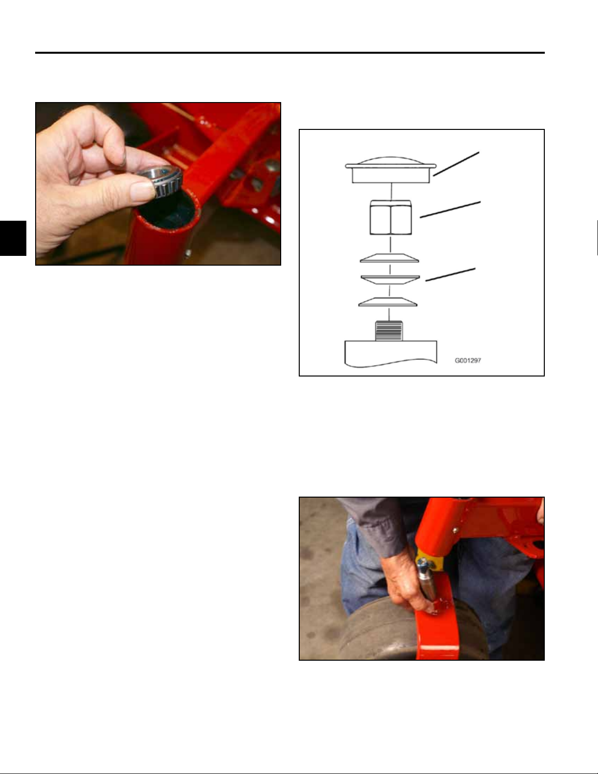
10. Install the upper bearing fork hub (Fig. 012).
Fig. 012 PICT-0372a
Caster Fork Assembly Installation
1. Install 3 Belleville washers as shown (Fig. 013).
C
B
A
Fig. 013 g. 69 G001297
A. Spring washer (3) C. Dust Cap
B. Lock nut
2. Slide the caster fork assembly into the hub (Fig.
014).
Fig. 014 PICT-0355
3-4 Toro Z Master G3 3000/5000/6000 Series Service Manual
Page 26
CHASSIS
3. Install the locknut. Tighten the locknut until the
Belleville washers are at, then back the nut off 1/4
turn to properly set the preload on the bearings (Fig.
015).
Fig. 015 PICT-0373a
4. Remove the plug located on the side of the caster
hub. Install a grease tting. Apply grease (No. 2
general purpose lithium base or molybdenum
grease) into the hub until it passes through the upper
bearing. Fill the top cavity with grease (Fig. 016).
Front Wheel Bearing Replacement
Front Wheel Bearing Removal
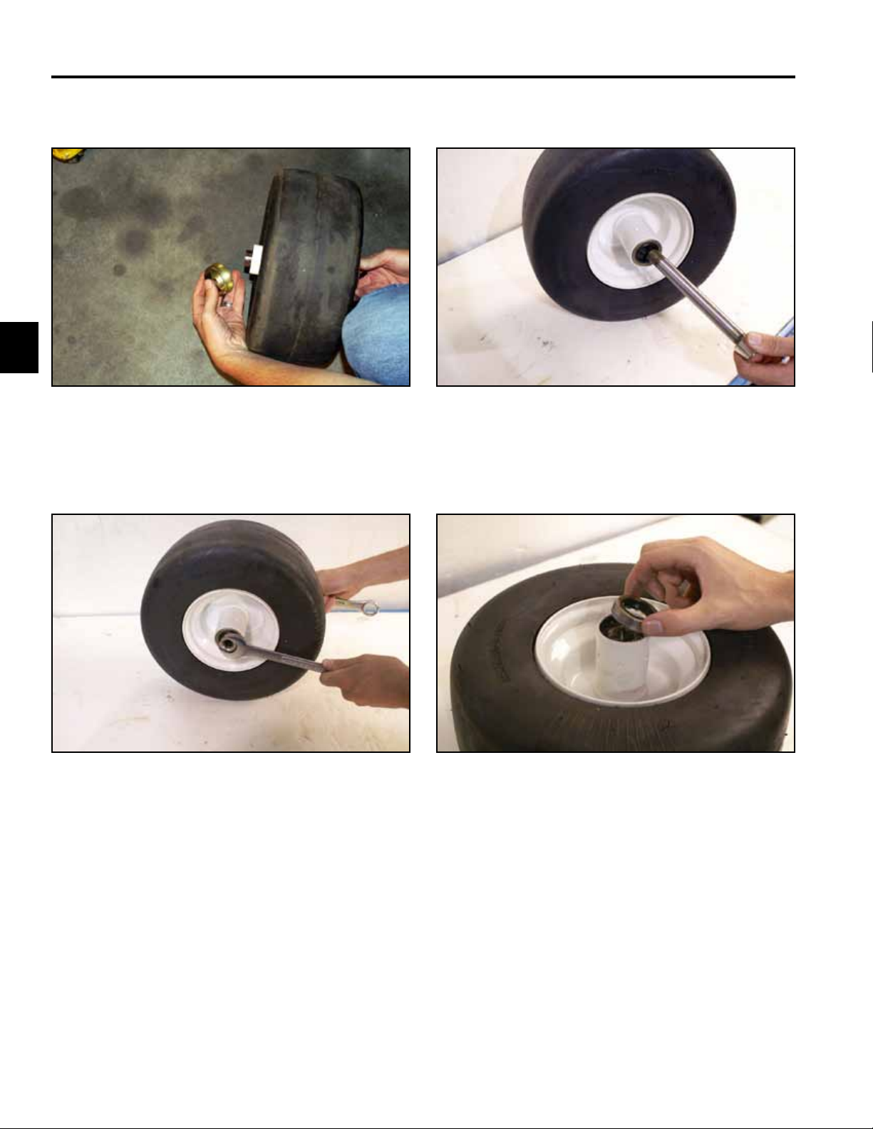
1. Raise the front of the machine off the ground.
2. Remove the wheel the axle bolt and nut (Fig. 017).
3
Fig. 017 PICT-0378a
3. Remove the wheel assembly from the fork (Fig.
018).
Fig. 016 PICT-0375a
5. Remove the grease tting and install the grease
plug.
Fig. 018 PICT-0379a
3-5Toro Z Master G3 3000/5000/6000 Series Service Manual
Page 27
CHASSIS
3
4. Remove the 2 seal guards (Fig. 019).
Fig. 019 PICT-0380a
5. Remove 2 spacer nuts from the axle caster (Fig.
020).
6. Remove the axle caster (Fig. 021).
Fig. 021 PICT-0383a
7. Remove the two caster seals from the wheel
assembly (Fig. 022).
Fig. 020 PICT-0382a
3-6 Toro Z Master G3 3000/5000/6000 Series Service Manual
Fig. 022 PICT-0384a
Page 28
CHASSIS
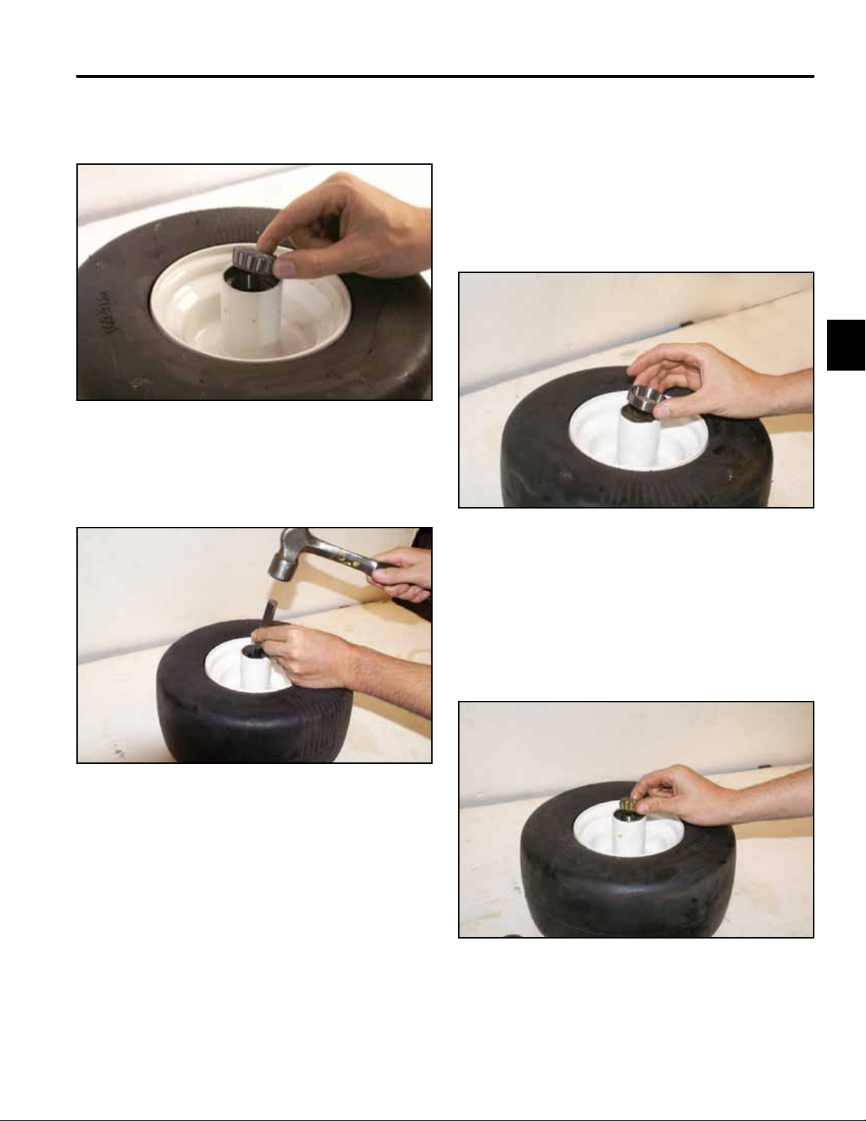
8. Remove the 2 tapered bearings from the wheel
assembly (Fig. 023).
Fig. 023 PICT-0385a
9. Drive the bearing cup out of the wheel assembly
(Fig. 024).
Front Wheel Bearing Installation
1. Install a new tapered bearing cup into the wheel
assembly by pressing each bearing cup into the
wheel hub so that the thicker part of the taper is
pressed into the wheel hub rst. The bearing cups
should seat against the shoulder divots inside the
wheel hub (Fig. 025).
3
Fig. 025 PICT-0389a
Fig. 024 PICT-0387a
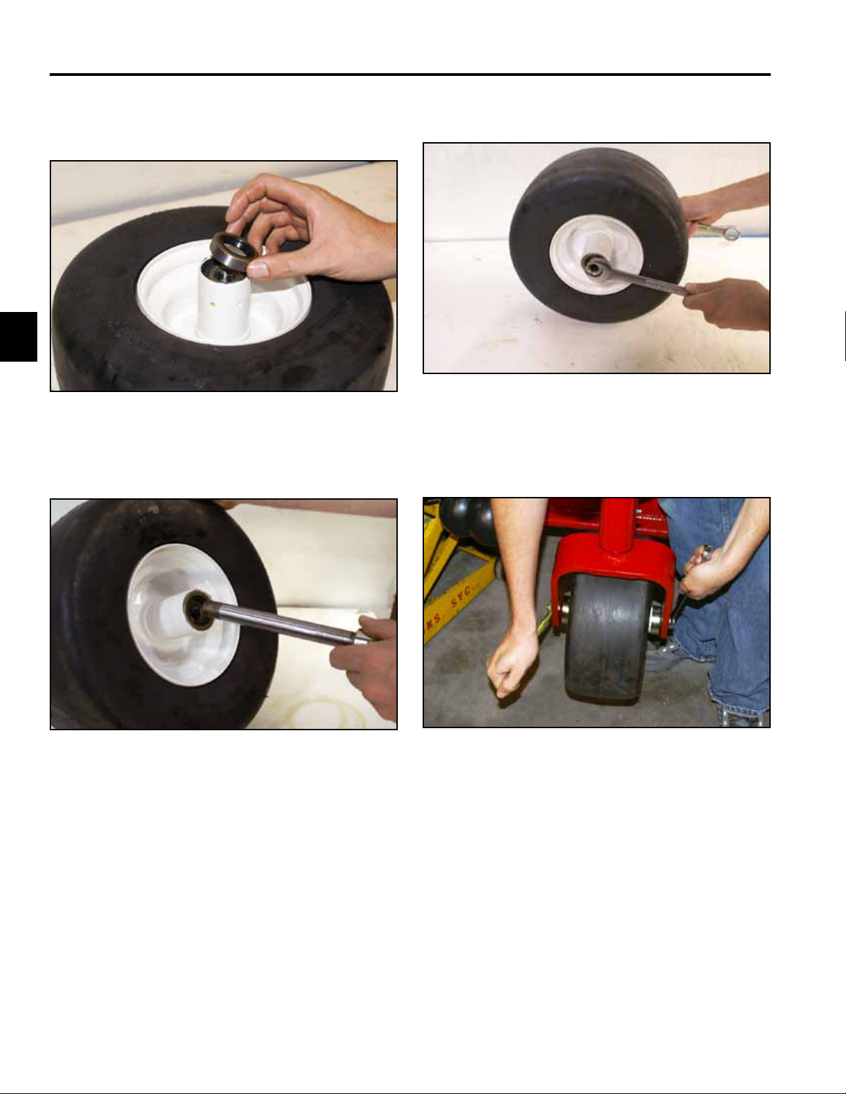
2. Pack both tapered bearings with grease (No. 2
general purpose lithium base or molybdenum
grease).
3. Install the tapered bearings into each side of the
wheel hub (Fig. 026).
Fig. 026 PICT-0390a
3-7Toro Z Master G3 3000/5000/6000 Series Service Manual
Page 29
CHASSIS
3
4. Install the grease seals into each side of the wheel
hub (Fig. 027).
Fig. 027 PICT-0392a
5. Install the caster axle (Fig. 028).
6. Install the 2 spacer nuts and tighten (Fig. 029).
Fig. 029 PICT-0382a
7. Install the two guard seals, screw, nut and tighten
(Fig. 030).
Fig. 028 PICT-0393a
3-8 Toro Z Master G3 3000/5000/6000 Series Service Manual
Fig. 030 PICT-0394a
Page 30
CHASSIS
Fuel Tank Replacement
Fuel Tank Removal
1. Turn the fuel valve to the “Off” position.
2. Siphon the fuel from the fuel tank.
Note: The only recommended way to remove the
fuel from the tank is by using a siphon pump.
3. Remove the 4 bolts retaining the seat base assembly to the frame (Fig. 031).
5. Remove the 4 screws retaining the right and left
hand motion control covers (Fig. 033).
3
Fig. 033 PICT-0412a
6. Remove the two bolts and nuts retaining the seat
mount to the frame (Fig. 034).
Fig. 031 PICT-0396a
4. Lift the seat up enough to remove the wiring plug to
the seat switch (Fig. 032).
Fig. 032 PICT-0398a
Fig. 034 PICT-0413a
3-9Toro Z Master G3 3000/5000/6000 Series Service Manual
Page 31

CHASSIS
3
7. Remove 2 bolts retaining the front of the seat mount
to the frame (Fig. 035).
Fig. 035 PICT-0401a
8. Lift the seat mount from the frame (Fig. 036).
9. Cut the tie strap around the fuel sender plug (Fig.
037).
Fig. 037 PICT-0406a
10. Unplug the fuel sender plug from the wiring harness
(Fig. 038).
Fig. 036 PICT-0417a
Fig. 038 PICT-0409a
3-10 Toro Z Master G3 3000/5000/6000 Series Service Manual
Page 32

CHASSIS
11. Disconnect the vapor line retainers from the fuel
manifold (Fig. 039).
Fig. 039 PICT-0421a
12. With the fuel valve in the OFF position, remove the
fuel clamp from the engine fuel line (Fig. 040).
13. Remove the fuel tank from the frame of the unit (Fig.
041).
3
Fig. 041 PICT-0426a
Fig. 040 PICT-0422a
3-11Toro Z Master G3 3000/5000/6000 Series Service Manual
Page 33

CHASSIS
3
Fuel Tank Installation
1. Install fuel tank into the frame (Fig. 042).
Fig. 042 PICT-0426a
2. Install the fuel clamp around the fuel line to the fuel
valve.
4. Plug the fuel sender plug to the wiring harness (Fig.
044).
Fig. 044 PICT-0409a
5. Install a tie strap around the red, yellow, and black
wires around the wiring connector (Fig. 045).
3. Connect the vapor line retainers to the fuel manifold
(Fig. 043).
Fig. 043 PICT-0421a
Fig. 045 PICT-0427a
3-12 Toro Z Master G3 3000/5000/6000 Series Service Manual
Page 34

CHASSIS
6. Install the seat mount to the frame (Fig. 046). 8. Install seat and connect the seat switch (Fig. 048).
3
Fig. 046 PICT-0415a
7. Install 2 bolts and nuts on the right and left side of
the seat frame (Fig. 047).
Fig. 047 PICT-0413a
Fig. 048 PICT-0398a
9. With ange nuts, tighten the seat and seat base to
the 4 seat isolators (Fig. 049).
Fig. 049 PICT-0396a
3-13Toro Z Master G3 3000/5000/6000 Series Service Manual
Page 35

CHASSIS
3
10. Install the right and left motion control covers with 2
screws each (Fig. 050).
Fig. 050 DSCN-4238a
11. Turn the valve to the “On” position.
Throttle Control Assembly Replacement (Kohler EFI Engine)
Throttle Control Assembly Removal
1. Disconnect the negative battery cable from the
battery terminal.
2. Remove the knob from the throttle control assembly
(Fig. 051).
Fig. 051 DSCN-4247a
3. Remove the 4 screws securing the control panel to
the RH Fender Console assembly (Fig. 052).
Fig. 052 DSCN-4249a
3-14 Toro Z Master G3 3000/5000/6000 Series Service Manual
Page 36

CHASSIS
4. Remove the locknuts and carriage bolts securing the
throttle control to the control panel (Fig. 053).
Fig. 053 DSCN-4250a
5. Loosen the cable clamp and remove the throttle
cable from underneath it (Fig. 054).
6. Remove the Z-bend end of the cable from the
throttle arm assembly (Fig. 055).
3
Fig. 055 DSCN-4258a
7. Slide the throttle cable through the hose clamp next
to the engine (Fig. 056).
Fig. 054 DSCN-4253a
Fig. 056 DSCN-4259a
3-15Toro Z Master G3 3000/5000/6000 Series Service Manual
Page 37

CHASSIS
3
8. Continue sliding the cable through the second
hose clamp next to the frame brace for the ROPS
assembly and pull the throttle cable out of the unit
(Fig. 057).
Fig. 057 DSCN-4260a
Throttle Control Assembly Installation
1. Slide the throttle cable through the hose clamp next
to the frame brace for the ROPS assembly (Fig.
058).
Fig. 058 DSCN-4260a
2. Slide the throttle cable through the hose clamp
located next to the engine (Fig. 059).
Fig. 059 DSCN-4259a
3-16 Toro Z Master G3 3000/5000/6000 Series Service Manual
Page 38

CHASSIS
3. Install the throttle control in the control panel using 2
carriage bolts and lock nuts (Fig. 060).
Fig. 060 DSCN-4250a
4. Install the 4 screws securing the control panel to the
RH Fender Console (Fig. 061).
5. Install the knob to the throttle control assembly (Fig.
062).
3
Fig. 062 DSCN-4247a
6. Move the throttle control to the slow idle position
(Fig. 063).
Fig. 061 DSCN-4249a
Fig. 063 DSCN-4277a
3-17Toro Z Master G3 3000/5000/6000 Series Service Manual
Page 39

CHASSIS
3
7. Install the throttle cable under the throttle clamp.
Install the throttle Z-bend in the middle hole on the
throttle arm assembly (Fig. 064).
Fig. 064 DSCN-4279a
8. Move the throttle arm assembly to the low idle
position and tighten the throttle cable clamp (Fig.
065).
Park Brake Handle Assembly Replacement (2012 & Later)
Park Brake Handle Removal (2012 & Later)
1. Remove the two screws retaining the right hand
motion control cover assembly to the frame and
remove the cover (Fig. 066).
Fig. 066 DSCN-2614a
Fig. 065 DSCN-4281a
9. Move the throttle control back and forth checking the
operation of the throttle arm assembly.
10. Connect the negative battery cable to the battery.
2. Unplug the wire harness from the park brake switch
(Fig. 067).
Fig. 067 DSCN-2617a
3-18 Toro Z Master G3 3000/5000/6000 Series Service Manual
Page 40

CHASSIS
3. Remove two screws and spacers retaining the park
brake handle assembly to the frame (Fig. 068).
Fig. 068 DSCN-2619a
4. Remove the two cotter pins and clevis pins retaining
the right and left park brake cables to the handle
assembly (Fig. 069).
5. Remove two e-rings retaining the park brake cables
to the park-brake pivot assembly and slide the
cables out of the slots. Remove the park-brake
handle assembly from the unit (Fig. 070).
3
Fig. 070 DSCN-2626a
Fig. 069 DSCN-2623a
3-19Toro Z Master G3 3000/5000/6000 Series Service Manual
Page 41

CHASSIS
3
Park Brake Handle Installation (2012 & Later)
1. Install the left and right brake cables in the slots in
the bottom of the brake pivot assembly and install
the e-rings (Fig. 071).
Fig. 071 DSCN-2627a
3. Install two screws through the park brake handle,
two spacers, and tighten the assembly to the frame
(Fig. 073).
Fig. 073 DSCN-2637a
4. Plug the wire harness to the park brake switch.
2. Install the clevis ends of the right and left brake
cables to the parking brake handle assembly using
two clevis pins and cotter pins (Fig. 072).
Fig. 072 DSCN-2635a
5. Install the two screws retaining the right hand
motion-control cover assembly to the frame and
tighten (Fig. 074).
Fig. 074 DSCN-2614a
6. Operate the park brake handle to make sure
everything is moving freely.
3-20 Toro Z Master G3 3000/5000/6000 Series Service Manual
Page 42

CHASSIS
Park Brake Cable Replacement (2011 & Prior)
Left Park Brake Cable Removal (2011 & Prior)
1. Raise the rear end of the unit and install jack stands
under the tie down loops on the frame. Remove the
RH and LH wheels from the unit (Fig. 075).
4. With needle nose pliers, squeeze the tabs on the
brake cable and pull the brake cable out of the slot in
the cable anchor (Fig. 077).
3
Fig. 077 PICT-8969a
5. Slide the brake cable out of the cable anchor and out
towards the front (Fig. 078).
Fig. 075 PICT-8962
2. Disengage the park brake lever.
3. Remove the two nuts located on the end of park
brake cable (Fig. 076).
Fig. 076 PICT-9075a
Fig. 078 PICT-8970a
3-21Toro Z Master G3 3000/5000/6000 Series Service Manual
Page 43

CHASSIS
3
6. Release the brake cable retainer holding the brake
cable to the cradle. Push the cable through the
routing hole and remove (Fig. 079).
Fig. 079 PICT-8974a
7. Remove the tie strap securing the brake cable to the
cradle (Fig. 080).
8. Remove the brake cable from the retainers located
on the cradle (Fig. 081).
Note: The cable is routed around the cradle.
C
B
D
D
A
Fig. 081 cables routing #4
A. Right side brake C. Left side brake
assembly assembly
B. Cradle D. Retainer (5)
Fig. 080 PICT-8977a
9. Remove the cotter pin located on the clevis pin holding the cable clevis to the brake lever (Fig. 082).
Fig. 082 PICT-8999a
3-22 Toro Z Master G3 3000/5000/6000 Series Service Manual
Page 44

CHASSIS
10. Remove the clevis pin from the cable yoke (Fig.
083).
Fig. 083 PICT-9001a
11. Release the brake cable retainer holding the brake
cable to the frame (Fig. 084).
12. Slide the cable out of the slot (Fig. 085).
3
Fig. 085 PICT-9014a
13. Pull the cable out over the frame cross bar and
remove it from the unit (Fig. 086).
Fig. 084 PICT-9008a
Fig. 086 PICT-9017a
3-23Toro Z Master G3 3000/5000/6000 Series Service Manual
Page 45

CHASSIS
3
Left Park Brake Cable Installation (2011 & Prior)
1. Route the clevis end of the brake cable over the
frame cross bar (Fig. 087).
Fig. 087 PICT-9017a
2. Route the brake cable up through the slotted hole in
the frame and push the snap end tting of the brake
cable into the slot (Fig. 088).
3. Position the brake cable clevis to the brake lever
assembly. Install a clevis pin through the brake cable
clevis and the brake lever assembly (Fig. 089).
Fig. 089 PICT-9001a
4. Install a cotter pin through the clevis pin to secure
(Fig. 090).
Fig. 090 PICT-8999a
Fig. 088 PICT-9021a
3-24 Toro Z Master G3 3000/5000/6000 Series Service Manual
Page 46

CHASSIS
5. Route the brake cable into the retainers on the
cradle following the routing diagram (Fig. 091).
C
B
D
D
A
Fig. 091 cables routing #4
A. Right side brake C. Left side brake
assembly assembly
B. Cradle D. Retainer (5)
7. Slide the brake cable behind the wheel hub and slide
the threaded end of the brake cable through the
trunnion located in the brake caliper (Fig. 093).
3
Fig. 093 PICT-9063a
8. Install the brake cable snap tting into the slotted
bracket (Fig. 094).
6. Install the left hand brake cable retainer into the
cradle so that the retainer tab is installed in the slot
on the cradle (Fig. 092).
Fig. 092 PICT-9027a
Fig. 094 PICT-9065a
3-25Toro Z Master G3 3000/5000/6000 Series Service Manual
Page 47

CHASSIS
3
9. Slide the rubber boot over the snap tting (Fig. 095).
Fig. 095 PICT-9077a
10. Install a tie strap securing the brake cable to the
cradle (Fig. 096).
11. Install a standard nut and a lock nut onto the
threaded brake cable rod (Fig. 097).
A B
Fig. 097 PICT-9075a
A. Standard nut B. Lock nut
12. Adjust the park brake. Refer to “Adjusting the
Parking Brake” on page 3-32.
Fig. 096 PICT-9070a
3-26 Toro Z Master G3 3000/5000/6000 Series Service Manual
Page 48

CHASSIS
Right Park Brake Cable Removal (2011 & Prior)
1. Raise the rear end of the unit and install jack stands
under the tie down loops on the frame. Remove the
RH and LH wheels from the unit (Fig. 098).
Fig. 098 PICT-8962
4. With needle nose pliers, squeeze the tabs on the
brake cable and pull brake cable out of the slot in the
cable anchor (Fig. 100).
3
Fig. 100 PICT-9083a
5. Slide the brake cable out of the cable anchor and out
towards the rear of the unit (Fig. 101).
2. Disengage the park brake lever.
3. Remove the two nuts located on the end of the park
brake cable (Fig. 099).
Fig. 099 PICT-9075
Fig. 101 PICT-9084a
3-27Toro Z Master G3 3000/5000/6000 Series Service Manual
Page 49

CHASSIS
3
6. Release the brake cable retainer holding the brake
cable to the cradle (Fig. 102).
Fig. 102 PICT-9085a
7. Guide the brake cable through the two holes in the
cradle (Fig. 103).
8. Pull the brake cable through the hole in the side of
the frame (Fig. 104).
Fig. 104 PICT-9087a
9. Remove the cotter pin located on the clevis pin
holding the brake cable clevis to the park brake lever
(Fig. 105).
C
B
E
D
D
A
E
Fig. 103 cables routing #4
A. Right side brake C. Left side brake
assembly assembly
B. Cradle D. Retainer (5)
E. Hole (2)
Fig. 105 PICT-9090a
3-28 Toro Z Master G3 3000/5000/6000 Series Service Manual
Page 50

CHASSIS
10. Squeeze the tabs on the brake cable snap tting and
remove the brake cable from the slot on the side of
the frame (Fig. 106).
Fig. 106 PICT-9092a
Right Park Brake Cable Installation (2011 & Prior)
1. Install the brake cable snap tting into the slot
located on the side of the frame (Fig. 107).
3
Fig. 107 PICT-9092a
2. Position the brake cable clevis to the brake lever
assembly. Install a clevis pin through the brake cable
clevis and the brake lever assembly (Fig. 108).
Fig. 108 PICT-9099a
3-29Toro Z Master G3 3000/5000/6000 Series Service Manual
Page 51

CHASSIS
3
3. Install a cotter pin through the clevis pin (Fig. 109).
Fig. 109 PICT-9101a
4. Install the rubber seal over the end of the brake snap
tting (Fig. 110).
5. Route the brake cable through the side hole in the
frame and down through the hole in the cradle (Fig.
111).
Fig. 111 PICT-9105a
6. Route the brake cable from the hole in the cradle,
back to the slot of the cradle (Fig. 112).
Fig. 110 PICT-9103a
C
B
E
D
D
A
E
Fig. 112 cables routing #4
A. Right side brake C. Left side brake
assembly assembly
B. Cradle D. Retainer (5)
E. Hole (2)
3-30 Toro Z Master G3 3000/5000/6000 Series Service Manual
Page 52

CHASSIS
7. Install the right hand brake cable retainer into the
cradle so that the retainer tab is installed in the slot
on the cradle (Fig. 113).
Fig. 113 PICT-9111a
8. Route the brake cable behind the wheel hub and
slide the threaded end into the trunnion on the
caliper (Fig. 114).
9. Install the snap tting into the slotted bracket (Fig.
115).
3
Fig. 115 PICT-9114a
10. Install a standard nut and a lock nut onto the
threaded brake cable rod (Fig. 116).
A B
Fig. 114 PICT-9113a
Fig. 116 PICT-9075a
A. Standard nut B. Lock nut
11. Adjust the park brake. Refer to “Adjusting the
Parking Brake” on page 3-32.
3-31Toro Z Master G3 3000/5000/6000 Series Service Manual
Page 53

CHASSIS
3
Adjusting the Parking Brake
1. Open the push valve (vertical position) on the hydro
unit that you are replacing the brake cable on (Fig.
117).
Fig. 117 PICT-8677a
2. Ensure the parking brake is disengaged.
Note: The left side brake is being adjusted in the
following steps; the right side adjustment is
performed the same way.
3. Using hands and ngers only, push the caliper lever
arm forward to engage the brake pads on the wheel
hub until the lever stops (Fig. 118).
A B
Fig. 118 PICT-8679a
A. Standard nut B. Lock nut
4. While holding the lever, use the other hand or ngers
to pull the cable threaded end tight through the
swivel. Spin the standard nut against the swivel (Fig.
119).
Fig. 119 PICT-8680a
3-32 Toro Z Master G3 3000/5000/6000 Series Service Manual
Page 54

CHASSIS
5. Try to turn the wheel hub in both directions relative
to the caliper. There should be slight movement
between them; some friction/resistance is acceptable.
6. If there is no movement between the hub rotor and
the caliper then back off the standard nut one turn
from the swivel and repeat step 5.
7. If the hub rotor moves freely relative to the caliper,
then tighten the standard nut one turn against the
swivel and repeat step 5.
8. Once step 5 is achieved, hold the threaded rod
end with a tool and tighten the lock nut against the
standard nut. Do not allow the cable to turn when the
lock nut is tightened (Fig. 120).
B C DE F G
A
9. Close the drive wheel release valve (horizontal
operating position) (Fig. 121).
3
Fig. 121 PICT-8677a
10. Install the RH and LH wheels on the unit and remove
both jack stands and lower the unit.
I
Fig. 120 g. 63 G010208
A. Cable anchor F. Lock nut
B. Threaded rod G. Pull cable threaded rod
C. Push lever this direction this direction
D. Caliper lever arm H. Hold threaded rod with
E. Standard nut (shown pliers
against swivel) I. Swivel (pivot head)
H
3-33Toro Z Master G3 3000/5000/6000 Series Service Manual
Page 55

CHASSIS
3
Park Brake Cable Replacement (2012 & Later)
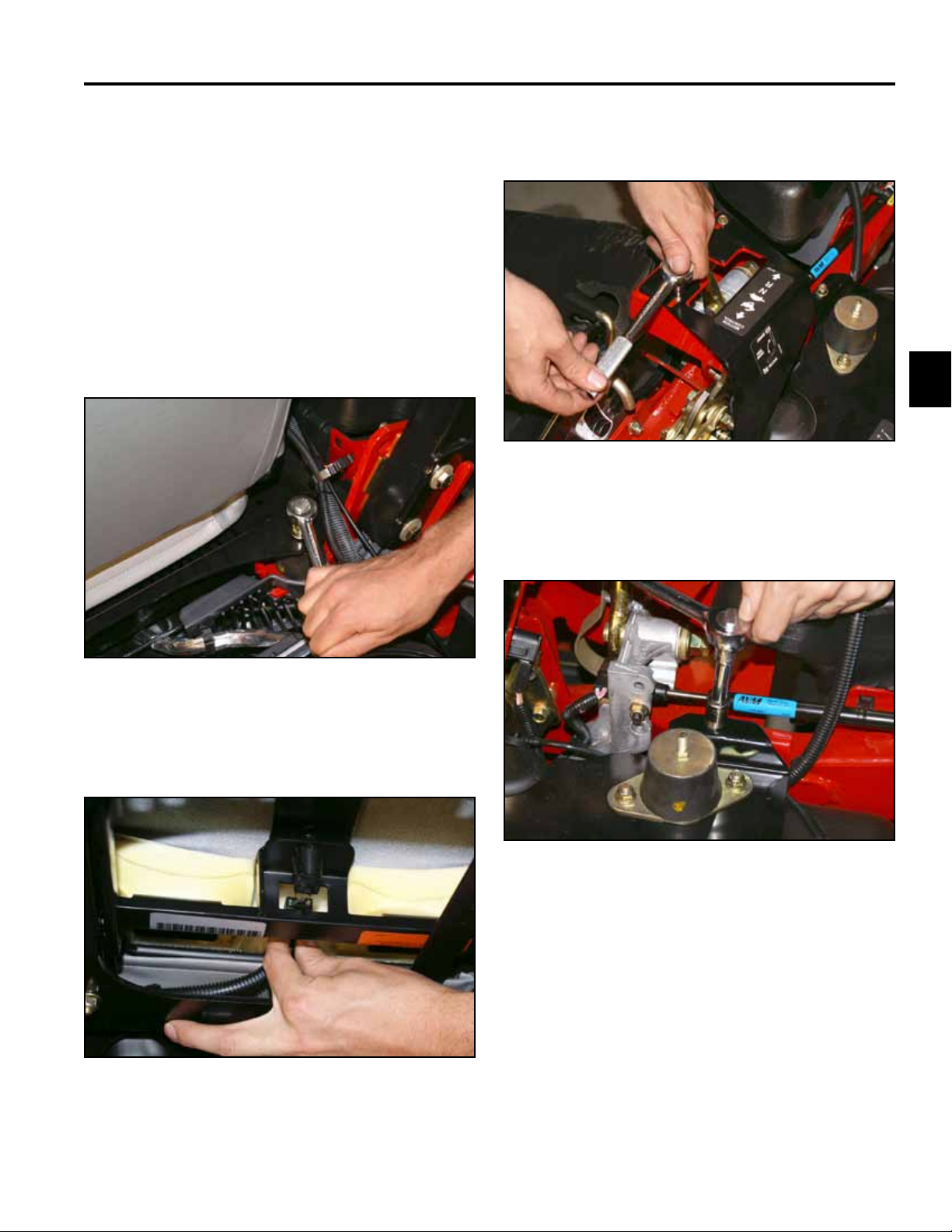
Left Park Brake Cable Removal (2012 & Later)
1. Raise the rear end of the unit and install jack stands
under the tie down loop on the frame. Remove the
RH and LH wheels from the unit (Fig. 122).
Fig. 122 DSCN-4311a
4. Hold the threaded rod end with a tool, and with a
socket wrench remove the lock nut and washer from
the end of the cable (Fig. 124). Continue to remove
the washer and spring.
Fig. 124 DSCN-4315a
5. Remove the e-ring from the groove in the cable end,
and the cable anchor located on the transmission
(Fig. 125).
2. Disengage the park brake lever.
3. Remove the e-ring, washer, and brake pin from the
L-Bracket (Fig. 123).
Fig. 123 DSCN-4314a
Fig. 125 DSCN-4318a
3-34 Toro Z Master G3 3000/5000/6000 Series Service Manual
Page 56

CHASSIS
6. Pull the brake cable out of the cable anchor on the
transmission and slide it out of the slot (Fig. 126).
Fig. 126 DSCN-4325a
7. Squeeze the tabs on the conduit tting and remove it
from cable bracket located on the frame (Fig. 127).
8. Remove the two clips retaining the brake cable to
the frame (Fig. 128).
3
Fig. 128 DSCN-4328a
9. Remove the two screws retaining the right hand
motion control cover assembly to the frame and
remove (Fig. 129).
Fig. 127 DSCN-4327a
Fig. 129 DSCN-2614a
3-35Toro Z Master G3 3000/5000/6000 Series Service Manual
Page 57

CHASSIS
3
10. Unplug the wire harness from the park brake switch
(Fig. 130).
Fig. 130 DSCN-2617a
11. Remove two screws and spacers retaining the park
brake handle assembly to the frame (Fig. 131).
12. Remove the cotter pin and clevis pin on the left side
of the park brake handle (Fig. 132).
Fig. 132 DSCN-4330a
13. Remove the e-ring retaining the brake cable to the
park brake pivot assembly and slide the cables out
of the slots (Fig. 133). Slide the brake cable out of
the unit.
Fig. 131 DSCN-2619a
Fig. 133 DSCN-4333
3-36 Toro Z Master G3 3000/5000/6000 Series Service Manual
Page 58

CHASSIS
Left Park Brake Cable Installation (2012 & Later)
1. Install brake cable with the clevis end out toward the
park brake handle (Fig. 134).
Fig. 134 DSCN-4358a
2. Install the brake cable grooved tting into the slot on
the bottom of the brake pivot assembly and install
e-ring (Fig. 135).
3. Install the clevis pin through the clevis end of the
brake cable to the park-brake handle assembly and
install a cotter pin (Fig. 136).
3
Fig. 136 DSCN-4330a
4. Install two screws and spacers through the park
brake handle and tighten the assembly to the frame
(Fig. 137).
Fig. 135 DSCN-4335a
Fig. 137 DSCN-2619a
3-37Toro Z Master G3 3000/5000/6000 Series Service Manual
Page 59

CHASSIS
3
5. Route the brake cable through the two clips located
under the frame of the unit and tighten (Fig. 138).
Fig. 138 DSCN-4328a
6. Squeeze the tabs on the conduit tting and install in
the cable bracket located on the frame (Fig. 139).
7. Slide the brake cable into the cable anchor slot on
the transmission (Fig. 140).
Fig. 140 DSCN-4325a
8. Install the end of the brake cable through the cable
anchor and install an e-ring (Fig. 141).
Fig. 139 DSCN-4327a
3-38 Toro Z Master G3 3000/5000/6000 Series Service Manual
Fig. 141 DSCN-4361a
Page 60

CHASSIS
9. Install the L-bracket, spring, washer, and nut on the
threaded end of the brake cable (Fig. 142).
Fig. 142 DSCN-4336a
10. Install the L-Bracket with brake pin, washer, and
e-ring to the brake caliper (Fig. 143).
11. Engage the parking brake. Measure the overall
length of the compression spring (Fig. 144). The
correct length should be between 1-1/2” and 1-9/16”
(3.8 and 4.9cm). If the spring length is within this
range, no adjustment is needed. If it is not, proceed.
A
B C D
F
A
E
H
FG
E
H
3
Fig. 143 DSCN-4314a
Fig. 144 g. 79 G016879
(Left Hand brake shown above)
A. Cable anchor E. Caliper
B. Hold threaded rod here F. Compression spring
C. Measure G. Threaded rod
D. Lock nut H. Hub
3-39Toro Z Master G3 3000/5000/6000 Series Service Manual
Page 61

CHASSIS
3
12. Hold the end of the threaded rod with a tool and
adjust the lock nut until the spring length is between
1-1/2” and 1-9/16” (3.8 and 4.0cm) (Fig. 145).
Note: Do not allow the cable to turn when the nut
are being turned.
Fig. 145 DSCN-4315a
13. Disengage the parking brake. Rotate the drive wheel
release handle to the released position. Turn the
wheel hub by hand in both directions relative to the
caliper; no drag of the caliper pad on the wheel hub
is desired.
16. Plug the wire harness to the park brake switch (Fig.
146).
Fig. 146 DSCN-2617a
17. Install the two screws retaining the right hand
motion-control cover assembly to the frame (Fig.
147).
14. After adjusting the brake, cycle the brake handle a
minimum of six times to allow the cable to seat into
the sheath and mounting tabs. Recheck the spring
length.
15. Rotate the drive wheel release handle to the
operating position.
Fig. 147 DSCN-2614a
18. Install the rear tires and torque lug nuts between
103.5 – 126.5 ft-lbs. (140.5 – 171.5 Nm).
19. Remove the jack stands and lower the unit.
3-40 Toro Z Master G3 3000/5000/6000 Series Service Manual
Page 62

CHASSIS
Right Park Brake Cable Removal (2012 & Later)
1. Raise the rear end of the unit and install jack stands
under the tie down loop on the frame. Remove the
RH and LH wheels from the unit (Fig. 148).
Fig. 148 DSCN-4311a
2. Disengage the park brake lever.
4. Hold the end of the threaded rod with a tool and with
a socket wrench remove the lock nut and washer
from the end of the cable (Fig. 150). Remove the
washer, spring and the L-Bracket.
3
Fig. 150 DSCN-4366a
5. Remove the e-ring from the groove in the cable end
and cable anchor located on the transmission (Fig.
151).
3. Remove the e-ring, washer, and brake pin from the
L-Bracket (Fig. 149).
Fig. 149 DSCN-4364a
Fig. 151 DSCN-4368
3-41Toro Z Master G3 3000/5000/6000 Series Service Manual
Page 63

CHASSIS
3
6. Pull the brake cable out of the cable anchor on the
transmission and slide it out of the slot (Fig. 152).
Fig. 152 DSCN-4370a
7. Remove the two screws retaining the right hand
motion control cover assembly to the frame and
remove (Fig. 153).
8. Unplug the wire harness from the park brake switch
(Fig. 154).
Fig. 154 DSCN-2617a
9. Remove two screws and spacers retaining the park
brake handle assembly to the frame (Fig. 155).
Fig. 155 DSCN-2619a
Fig. 153 DSCN-2614a
3-42 Toro Z Master G3 3000/5000/6000 Series Service Manual
Page 64

CHASSIS
10. Remove the cotter pin and clevis pin on the right
side of the park brake handle (Fig. 156).
Fig. 156 DSCN-4373a
11. Remove the e-ring retaining the brake cable to the
park-brake pivot assembly and slide the cable out of
the slot (Fig. 157).
12. Remove the brake cable from the unit (Fig. 158).
3
Fig. 158 DSCN-4379a
Fig. 157 DSCN-4377a
3-43Toro Z Master G3 3000/5000/6000 Series Service Manual
Page 65

CHASSIS
3
Right Park Brake Cable Installation (2012 & Later)
1. Install brake cable with the clevis end out toward the
park brake handle (Fig. 159).
Fig. 159 DSCN-4385a
3. Install the clevis and cotter pin to the right side of the
park brake handle (Fig. 161).
Fig. 161 DSCN-4373a
4. Install two screws and spacers retaining the park
brake handle assembly to the frame (Fig. 162).
2. Install the brake cable grooved tting into the slot on
the bottom of the brake pivot assembly and install
the e-ring (Fig. 160).
Fig. 160 DSCN-4375a
Fig. 162 DSCN-2619a
3-44 Toro Z Master G3 3000/5000/6000 Series Service Manual
Page 66

CHASSIS
5. Route the brake cable back to the inside of the
frame (Fig. 163).
Fig. 163 DSCN-4379a
6. Slide the brake cable into the cable anchor slot on
the transmission (Fig. 164).
7. Install the end of the brake cable through the cable
anchor and install the e-ring (Fig. 165).
3
Fig. 165 DSCN-4370a
8. Install the L-Bracket, spring, washer, and nut on the
threaded end of the brake cable (Fig. 166).
Fig. 164 DSCN-4370a
Fig. 166 DSCN-4314a
3-45Toro Z Master G3 3000/5000/6000 Series Service Manual
Page 67

CHASSIS
3
9. Engage the parking brake. Measure the overall
length of the compression spring (Fig. 167).
Measure the overall length of the compression
spring. The correct length should be between 1-1/2”
and 1-9/16” (3.8 and 4.9cm). If the spring length is
within this range, no adjustment is needed. If it is
not, proceed.
A
B C D
F
A
E
H
FG
E
10. Hold the end of the threaded rod with a tool and
adjust the lock nut until the spring length is between
1-1/2” and 1-9/16” (3.8 and 4.0cm) (Fig. 168).
Note: DO NOT allow the cable to turn when the nuts
are being turned.
Fig. 168 DSCN-4315a
H
Fig. 167 g. 79 G016879
(Left Hand brake shown above)
A. Cable anchor E. Caliper
B. Hold threaded rod here F. Compression spring
C. Measure G. Threaded rod
D. Lock nut H. Hub
11. Disengage the parking brake. Rotate the drive wheel
release handle to the released position. Turn the
wheel hub by hand in both directions relative to the
caliper; no drag of the caliper pad on the wheel hub
is desired.
12. After adjusting the brake, cycle the brake handle a
minimum of six times to allow the cable to seat into
the sheath and mounting tabs. Recheck the spring
length.
13. Rotate the drive wheel release handle to the
operating position.
3-46 Toro Z Master G3 3000/5000/6000 Series Service Manual
Page 68

CHASSIS
14. Plug the wire harness to the park brake switch (Fig.
169).
Fig. 169 DSCN-2617a
15. Install the two screws retaining the right hand
motion-control cover assembly to the frame (Fig.
170).
Brake Caliper Replacement
Brake Caliper Removal
Note: The left side is being removed; use the same
instructions for right side removal.
1. Raise the rear end of the unit and install jack stands
under the tie down loop on the frame. Remove the
wheel.
2. Disengage the park brake lever.
3. Remove the e-ring, washer, and brake pin from the
L-Bracket (Fig. 171).
3
Fig. 170 DSCN-2614a
16. Install the rear tires and torque lug nuts between
103.5 – 126.5 ft-lbs. (140.5 – 171.5 Nm).
17. Remove the jack stands and lower the unit.
Fig. 171 DSCN-4314a
3-47Toro Z Master G3 3000/5000/6000 Series Service Manual
Page 69

CHASSIS
3
4. Hold the end of the threaded rod with a tool,
and with a socket wrench, remove the lock nut
and washer from the end of the cable (Fig. 172).
Remove the washer and spring.
Fig. 172 DSCN-4315a
5. Remove the two bolts retaining the brake mount
plate to the transmission (Fig. 173).
6. Remove the brake caliper from the transmission
(Fig. 174).
Fig. 174 DSCN-4392a
7. Remove the brake mount plate from the caliper (Fig.
175).
Fig. 175 DSCN-4394a
Fig. 173 DSCN-4388a
3-48 Toro Z Master G3 3000/5000/6000 Series Service Manual
Page 70

CHASSIS
Brake Caliper Installation
1. Install the brake mount plate to the caliper (Fig. 176).
Fig. 176 DSCN-4398a
2. Apply thread locker to the 2 bolts that retain the
brake mount plate (Fig. 177).
3. Install two washers between the brake mount plate
and the transmission and tighten the bolts (Fig. 178).
3
Fig. 178 DSCN-4402a
4. Install the L-bracket, spring, washer, and nut on the
threaded end of the brake cable (Fig. 179).
Fig. 177 DSCN-4400a
Fig. 179 DSCN-4314a
3-49Toro Z Master G3 3000/5000/6000 Series Service Manual
Page 71

CHASSIS
3
5. Engage the parking brake. Measure the overall
length of the compression spring (Fig. 180). The
correct length should be between 1-1/2” and 1-9/16”
(3.8 and 4.9cm). If the spring length is within this
range, no adjustment is needed. If it is not, proceed.
A
B C D
F
A
E
H
FG
E
H
Fig. 180 g. 79 G016879
(Left Hand brake shown above)
A. Cable anchor E. Caliper
B. Hold threaded rod here F. Compression spring
C. Measure G. Threaded rod
D. Lock nut H. Hub
6. Hold the end of the threaded rod with a tool, and
adjust the lock nut until the spring length is between
1-1/2” and 1-9/16” (3.8 and 4.0cm) (Fig. 181).
Note: DO NOT allow the cable to turn when the nuts
are being turned.
Fig. 181 DSCN-4315a
7. Disengage the parking brake. Rotate the drive wheel
release handle to the released position. Turn the
wheel hub by hand in both directions relative to the
relative to the caliper; no drag of the caliper pad on
the wheel hub is desired.
8. After adjusting the brake, cycle the brake handle a
minimum of six times to allow the cable to seat into
the sheath and mounting tabs. Recheck the spring
length.
9. Rotate the drive wheel release handle to the
operating position.
10. Install the rear tire and torque lug nuts between
103.5 – 126.5 ft-lbs. (140.5 – 171.5 Nm).
11. Remove the jack stands and lower the unit.
3-50 Toro Z Master G3 3000/5000/6000 Series Service Manual
Page 72

CHASSIS
Motion Control Damper Replacement
Note: There is a right and left motion control
damper. The following removal and installa
tion procedures are on the left damper. The
procedure is the same for the right damper.
Motion Control Damper Removal
1. Park the machine on a level surface, disengage the
PTO, turn the ignition OFF and remove the key.
2. Remove the nut securing the damper ball joint to the
frame.
Note: You will need a T40 Torx wrench to hold the
bolt while removing (Fig. 182).
3. Remove the nut securing the damper to the motion
control assembly (Fig. 183).
3
Fig. 183 DSCN-4448a
4. Remove the damper assembly (Fig. 184).
Fig. 182 DSCN-4445a
Fig. 184 DSCN-4450a
3-51Toro Z Master G3 3000/5000/6000 Series Service Manual
Page 73

CHASSIS
3
Motion Control Damper Installation
Motion Control Damper (Fig. 185)
A
Fig. 185 DSCN-4452a
A. Belleville washer
Adjusting the Motion Control Damper
Note: The top damper mounting bolt can be adjust
ed to obtain a more desired motion control
lever resistance. See Figure 187 for mounting
options.
A B C
E
D
1. Install the damper with ball joint end that has the
Belleville washer into the frame. Torque the lock nut
to 200 in-lbs. (16.7 ft-lbs. or 22.6 Nm) (Fig. 186).
Fig. 186 DSCN-4450a
2. Install the other end of the damper to the motion
control assembly, normally in the center hole and
tighten the lock nut to 200 in-lbs. (16.7 ft-lbs. or 22.6
Nm). For adjustments, see “Adjusting the Motion
Control Damper” on page 3-52.
Fig. 187 g. 87 G008620
A. Torque the lock nut to 200 in-lbs. (16.7 ft-lbs. or 22.6
Nm). Bolt must protrude past end of locknut after
torque.
B. Most resistance (rmest feel)
C. Damper
D. Medium resistance (medium feel)
E. Least resistance (softest feel)
3-52 Toro Z Master G3 3000/5000/6000 Series Service Manual
Page 74

CHASSIS
Adjusting the Motion Control Neutral Lock Pivot
Note: The anged nut can be adjusted to obtain a
more desired motion control lever resistance
when moving it to the neutral lock position.
See Figure 188 for adjustment options.
A
B
Fig. 188 g. 88 G008621
A. Flanged nut B. Jam nut
Adjusting the Control Handle
Position
Note: There are two height positions for the control
levers; high and low. Remove the bolts to
adjust the height for the operator.
1. Disengage the PTO, move the motion control levers
to the neutral locked position, and set the parking
brake.
2. Stop the engine, remove the key, and wait for all
moving parts to stop before leaving the operating
position.
3. Loosen the bolts and ange nuts installed (Fig. 189).
A
B
3
1. Loosen the jam nut.
2. Tighten or loosen the anged nut to the desired feel.
For more resistance, tighten the ange nut. For less
resistance, loosen the ange nut.
3. Tighten jam nut.
C
Fig. 189 g. 84 G009040
A. Bolt C. Control lever
B. Handle D. Nut
D
3-53Toro Z Master G3 3000/5000/6000 Series Service Manual
Page 75

CHASSIS
3
4. Align the levers front to rear position by bringing the
levers together to the neutral position and slide them
until they are aligned, then tighten the bolts (Fig.
190).
Motion Control Assembly Replacement
Motion Control Assembly Removal
Note: This procedure is performed on the left hand
motion control assembly; follow the same
procedure for the right hand side.
1. Park the machine on a level surface, disengage
the PTO, turn the ignition key to OFF position and
remove the key.
2. Remove the 2 screws retaining the LH motion
control cover assembly (Fig. 191).
Fig. 190 g. 85 G009195
Fig. 191 DSCN-4454
3-54 Toro Z Master G3 3000/5000/6000 Series Service Manual
Page 76

CHASSIS
3. Remove the two bolts and nuts retaining the LH
steering handle assembly to the LH lever-control
motion (Fig. 192).
Fig. 192 DSCN-4459a
4. Remove the lock nut from the damper motion control
from the LH motion control assembly (Fig. 193).
5. Remove the plug connector to the neutral switch
(Fig. 194).
3
Fig. 194 DSCN-4464a
6. Remove the wire harness from the wire anchor on
the LH motion control assembly (Fig. 195).
Fig. 193 DSCN-4462a
Fig. 195 DSCN-4466a
3-55Toro Z Master G3 3000/5000/6000 Series Service Manual
Page 77

CHASSIS
3
7. Remove screw, at washer and nut retaining
the front pump linkage to the LH motion control
assembly (Fig. 196).
Fig. 196 DSCN-4470a
8. Remove the bolt securing the pivot hub and the LH
motion control to the frame (Fig. 197).
9. Remove the pivot hub from the LH motion control
(Fig. 198).
Fig. 198 DSCN-4474a
10. Remove the wire harness anchor from the LH
motion control (Fig. 199).
Fig. 199 DSCN-4475
Fig. 197 DSCN-4473a
3-56 Toro Z Master G3 3000/5000/6000 Series Service Manual
Page 78

CHASSIS
11. Remove the neutral switch from the LH motion
control (Fig. 200).
Fig. 200 DSCN-4476a
12. Remove the carriage bolt and nut retaining the leaf
spring to the LH motion control (Fig. 201).
13. Remove the jam nut from the LH motion control
lever (Fig. 202).
3
Fig. 202 DSCN-4480
14. Remove the nut, two spring washers, at washer
and LH motion control lever from the LH motion
control (Fig. 203).
Fig. 201 DSCN-4492b
E
A B C C D
Fig. 203 DSCN-4485a
A. Jam nut D. Flat washer
B. Nut E. LH motion control
C. Spring washer (2) F. Motion control lever
F
3-57Toro Z Master G3 3000/5000/6000 Series Service Manual
Page 79

CHASSIS
3
Motion Control Assembly Installation
1. Install 4 new ange bushings in the LH motion
control (Fig. 204).
Fig. 204 DSCN-4487a
2. Install motion control lever in the LH motion control
(Fig. 205).
3. Install at washer on motion control lever (Fig. 206).
Fig. 206 DSCN-4489a
4. Install the two spring washers with the crown side of
the washers facing out (Fig. 207).
Fig. 207 DSCN-4490
Fig. 205 DSCN-4488a
3-58 Toro Z Master G3 3000/5000/6000 Series Service Manual
Page 80

CHASSIS
5. Install the nut and tighten so it is snug (Fig. 208).
Fig. 208 DSCN-4491a
6. Install the spring leaf with carriage bolt and nut (Fig.
209).
7. Install the neutral switch to the motion control lever
(Fig. 210).
3
Fig. 210 DSCN-4495a
8. Install the wire harness anchor to the motion control
lever (Fig. 211).
Fig. 209 DSCN-4492a
Fig. 211 DSCN-4496a
3-59Toro Z Master G3 3000/5000/6000 Series Service Manual
Page 81

CHASSIS
3
9. Secure the LH control assembly to the frame with a
bolt and the pivot tube (Fig. 212).
Fig. 212 DSCN-4473a
10. Install the plug connector to the neutral switch (Fig.
213).
11. Install the wiring harness in the wire anchor located
on the LH motion control assembly (Fig. 214).
Fig. 214 DSCN-4502a
12. Install the lock nut from the damper motion control to
the LH motion control assembly (Fig. 215).
Fig. 213 DSCN-4500a
3-60 Toro Z Master G3 3000/5000/6000 Series Service Manual
Fig. 215 DSCN-4462a
Page 82

CHASSIS
13. Secure the front pump linkage assembly to the LH
motion control assembly with a bolt, washer and nut.
Note: The washer must be installed between the LH
motion control assembly and the ball joint on
the front pump linkage assembly (Fig. 216).
Fig. 216 DSCN-4470a
14. Install the two bolts and nuts retaining the LH
steering handle assembly to the LH motion control
lever (Fig. 217).
16. Install the 2 screws retaining the LH motion control
cover assembly (Fig. 218).
3
Fig. 218 DSCN-4454a
17. Start the unit, disengage the park brake lever, and
run for about 5 minutes operating the forward and
reverse handle forward/reverse. Move the motion
control lever to the neutral position and observe the
rear tire for movement. If the rear tire creeps in the
forward position, perform a neutral adjustment. A
slight creep in reverse is allowable. See “Adjusting
the Motion Control Linkage (Neutral Adjustment)” on
page 5-34.
Fig. 217 DSCN-4459a
15. For adjustments on the control handles and the
motion control neutral lock, see “Adjusting the
Motion Control Neutral Lock Pivot” on page 3-53
and “Adjusting the Control Handle Position” on page
3-53.
3-61Toro Z Master G3 3000/5000/6000 Series Service Manual
Page 83

3
CHASSIS
THIS PAGE INTENTIONALLY LEFT BLANK.
3-62 Toro Z Master G3 3000/5000/6000 Series Service Manual
Page 84

ENGINE
Engine Replacement
Note: The following procedure for removing and
installing the engine was performed on a
Kohler 29 HP EFI engine. You can follow the
same procedures for removing other engines
from the Z Master G3, 3000, 5000, and 6000
Series units.
Engine Removal
1. Remove the battery negative and positive cables.
Remove the battery from the frame.
2. On tilt seats, lift the seat up, or non-tilt seats, slide
the seat forward and turn the fuel shut off valve to
the OFF position (Fig. 219).
3. Raise the machine in the rear and support it with
jack stands (Fig. 220).
Fig. 220 DSCN-0071a
4
4. Remove the 3 carriage bolts and nuts retaining the
RH bumper to the frame (Fig. 221).
Fig. 219 DSCN-4635a
Fig. 221 DSCN-4637a
4-1Toro Z Master G3 3000/5000/6000 Series Service Manual
Page 85

ENGINE
4
5. Remove the 3 carriage bolts and nuts retaining the
LH bumper to the frame and rear guard (Fig. 222).
Fig. 222 DSCN-0004a
6. Remove the 2 nuts retaining the rear guard to the
frame and 1 carriage bolt and nut retaining the
mufer guard to the rear guard (Fig. 223).
7. Loosen the cable clamp and remove the throttle
cable (Fig. 224).
Fig. 224 DSCN-4253a
8. Remove the z-bend end of the cable from the throttle
arm assembly (Fig. 225).
Fig. 225 DSCN-4258a
Fig. 223 DSCN-0012a
4-2 Toro Z Master G3 3000/5000/6000 Series Service Manual
Page 86

ENGINE
9. Remove the fuel line from the fuel lter (Fig. 226).
Fig. 226 DSCN-0013a
10. Remove the fuel hose from the hose clamp and pull
the hose forward away from the engine (Fig. 227).
11. Remove the vent line from the air lter assembly
(Fig. 228).
Fig. 228 DSCN-0018a
4
12. Lift and remove the oor pan; then, with a 3/8”
breaker bar in the hole for the idler arm, turn
clockwise to loosen the mower deck drive-belt and
remove it from the electric PTO clutch (Fig. 229).
Fig. 227 DSCN-0011a
Fig. 229 DSCN-0020a
4-3Toro Z Master G3 3000/5000/6000 Series Service Manual
Page 87

ENGINE
4
13. Using a 1/2” drive breaker bar installed in the square
hole in the pump idler assembly, rotate the pump
idler arm counter-clockwise to relieve tension on the
v-belt (Fig. 230). Remove the v-belt from around the
engine drive pulley.
Fig. 230 DSCN-0025a
14. Unplug the wire plug from the electric PTO clutch
(Fig. 231).
15. Remove the bolt, spring washers, and washer
retaining the electric PTO to the engine crankshaft
(Fig. 232). Slide the clutch off the crankshaft.
Fig. 232 DSCN-0031a
16. Remove the engine sheave from the engine
crankshaft (Fig. 233).
Fig. 233 DSCN-0032a
Fig. 231 DSCN-0028a
4-4 Toro Z Master G3 3000/5000/6000 Series Service Manual
Page 88

ENGINE
17. Remove the key from the engine crankshaft (Fig.
234).
Fig. 234 DSCN-0034a
18. Remove the 4 engine bolts and Belleville washers
retaining the engine to the frame (Fig. 235).
19. With a hoist raise the engine approximately 6” above
the frame (Fig. 236).
Fig. 236 DSCN-0047a
4
20. Remove the starter motor bolt at the top of the
starter, then remove the battery ground wire and the
wiring harness ground wire (Fig. 237).
Fig. 235 DSCN-0038a
Fig. 237 DSCN-0043a
4-5Toro Z Master G3 3000/5000/6000 Series Service Manual
Page 89

ENGINE
4
21. Unplug the wiring harness plug from the engine
harness plug (Fig. 238).
Fig. 238 DSCN-0049a
22. On the bottom of the starter solenoid disconnect the
red wire and red positive cable (Fig. 239).
23. Remove the engine from the frame (Fig. 240).
Fig. 240 DSCN-0053a
Fig. 239 DSCN-0050a
4-6 Toro Z Master G3 3000/5000/6000 Series Service Manual
Page 90

ENGINE
Engine Installation
1. Place the engine approximately 6” above the frame
in the engine bay area.
2. Install the battery ground cable and wiring harness
ground wire to the starter motor bolt (Fig. 241).
Fig. 241 DSCN-0043a
3. Install red positive cable and red wire to the bottom
of the starter solenoid (Fig. 242).
4. Plug the wiring harness plug into the engine wiring
harness plug connector (Fig. 243).
Fig. 243 DSCN-0049a
4
5. Lower the engine to the frame.
6. Align the four holes of the engine base to the frame
using 4 bolts and Belleville washers. Torque the
bolts to 30 ± 3 ft-lbs. (40.7 ± 4.07 Nm) (Fig. 244).
Fig. 242 DSCN-0050a
Fig. 244 DSCN-0055
4-7Toro Z Master G3 3000/5000/6000 Series Service Manual
Page 91

ENGINE
4
7. Install the key to the engine crankshaft (Fig. 245).
Fig. 245 DSCN-0034a
8. Install the engine sheave on the crankshaft (Fig.
246).
9. Install the bolt, spring washers (with crown of the
washers facing the bolt head), and washer (Fig.
247).
C
B
A
Fig. 247 DSCN-0060a
A. Bolt C. Washer
B. Spring Washer (2)
Fig. 246 DSCN-0032a
10. Install the electric PTO clutch on the crankshaft,
make sure the slot on the clutch ts on the clutch
anchor. Using the bolt, spring washers, and washer
torque the clutch bolt to 55 ± 6 ft-lbs. (74.6 ± 8.1 Nm)
(Fig. 248).
Fig. 248 DSCN-0061a
4-8 Toro Z Master G3 3000/5000/6000 Series Service Manual
Page 92

ENGINE
11. Plug the clutch wire plug into the electric PTO clutch
(Fig. 249).
Fig. 249 DSCN-0028a
12. Using a 1/2” drive breaker bar installed in the square
hole in the pump idler assembly, rotate the pump
idler arm counter-clockwise to allow room to install
the v-belt around the engine pulley (Fig. 250).
13. Using a 3/8” breaker bar, install the mower idler arm
assembly and relieve the tension on the idler arm
assembly. Install the mower drive belt around the
electric PTO clutch (Fig. 251).
Fig. 251 DSCN-0020a
14. Install the oor pan.
15. Install the vent line to the air lter assembly (Fig.
252).
4
Fig. 250 DSCN-0025a
Fig. 252 DSCN-0018a
4-9Toro Z Master G3 3000/5000/6000 Series Service Manual
Page 93

ENGINE
4
16. Route the fuel line and the throttle cable through
the hose clamp located on the right hand side of the
frame next to the battery box (Fig. 253).
Fig. 253 DSCN-0063a
17. Install the fuel line and fuel clamp on the fuel lter
(Fig. 254).
18. Slide the throttle cable through the hose clamp
located next to the engine (Fig. 255).
Fig. 255 DSCN-4259a
19. Install the z-bend of the throttle cable into the middle
hole in the throttle arm assembly (Fig. 256).
Fig. 256 DSCN-4261
Fig. 254 DSCN-0013a
4-10 Toro Z Master G3 3000/5000/6000 Series Service Manual
Page 94

ENGINE
20. Install the throttle cable in the cable clamp (Fig.
257).
Fig. 257 DSCN-4253a
21. Move the throttle control to the slow idle position
(Fig. 258).
22. Move the throttle arm assembly to the low-idle
position and tighten the throttle cable clamp (Fig.
259).
Fig. 259 DSCN-4281a
4
23. Move the throttle control back and forth, checking
the operation of the throttle arm assembly.
Fig. 258 DSCN-4277a
24. Install 2 nuts retaining the rear guard to the frame
and 1 carriage bolt nut retaining the mufer guard to
the rear guard (Fig. 260).
Fig. 260 DSCN-0012a
4-11Toro Z Master G3 3000/5000/6000 Series Service Manual
Page 95

4
ENGINE
25. Install 3 carriage bolts and nuts retaining the LH
bumper to the frame and rear guard (Fig. 261).
Fig. 261 DSCN-0004a
26. Install the 3 carriage bolts and nuts retaining the RH
bumper to the frame and rear guard (Fig. 262).
Fig. 262 DSCN-4637a
27. Turn the fuel shut off valve to the “On” position; for
tilt seats, lift the seat; for non-tilt seats, slide the seat
forward to access the fuel shut off valve.
28. Lower the machine to the ground with a oor jack,
after removing the jack stands.
29. Install the battery in the frame. Install the positive
and negative battery cables.
4-12 Toro Z Master G3 3000/5000/6000 Series Service Manual
Page 96

HYDRAULIC SYSTEM
Hydrostatic Pump Removal
Note: Cleanliness is a key factor in a successful
repair of any hydrostatic system. Thoroughly
clean all exposed surfaces prior to any type
of maintenance. Cleaning all parts by using
a solvent wash and air-drying is usually
adequate. As with any precision equipment,
all parts must be kept free of foreign material
and chemicals. Protect all exposed sealing
areas and open cavities from damage and
foreign material.
G3 UHT Transmission Replacement (2009 through 2011 models)
Note: The following procedures cover replacing
the left hand UHT Transmission. The same
procedures can be followed to remove the
right hand UHT Transmission.
4. Remove the negative battery cable from the battery
(Fig. 263).
Fig. 263 PICT-8541a
5. Raise the seat and remove the guard from above the
UHT that is being replaced (Fig. 264).
G3 UHT Transmission Removal (2009 - 2011 models)
1. Position the machine on a level surface.
2. Disengage the PTO, move the motion control levers
to the neutral locked position and set the parking
brake.
3. Stop the engine, remove the key, and wait for all
moving parts to stop before leaving the operating
position.
5
Fig. 264 PICT-8695a
5-1Toro Z Master G3 3000/5000/6000 Series Service Manual
Page 97

HYDRAULIC SYSTEM
5
6. Lower the mower deck to the lowest position. Lift the
oor pan up and remove it (Fig. 265).
Note: On international models, unbolt the oor pan.
Fig. 265 PICT-8543
7. With a 3/8” drive breaker bar installed in the square
hole of the idler bracket, rotate the idler bracket
clockwise to relieve belt tension (Fig. 266).
8. Remove the mower deck drive belt from the center
mower spindle pulley (Fig. 267).
Fig. 267 PICT-8546a
9. Remove the mower deck drive belt from around the
electric PTO clutch and pull the belt forward so it
clears the hydro cradle assembly (Fig. 268).
Fig. 268 PICT-8693a
Fig. 266 PICT-8545a
5-2 Toro Z Master G3 3000/5000/6000 Series Service Manual
Page 98

HYDRAULIC SYSTEM
10. Raise the rear of the unit and support it with 2 jack
stands placed under the right and left tie down loops
(Fig. 269).
Note: Tires should be at least 6” (15.2cm) off the
oor.
Fig. 269 PICT-8548
11. Remove the two rear wheels (Fig. 270).
12. Using a 1/2” drive breaker bar installed in the square
hole in the pump idler assembly, rotate the pump
idler arm counter-clockwise to relieve tension on the
v-belt (Fig. 271).
Fig. 271 PICT-8557a
13. With tension removed, remove the v-belt from
around the transmission pulleys and the engine drive
pulley (Fig. 272).
5
Fig. 270 PICT-8550a
Fig. 272 PICT-8561a
5-3Toro Z Master G3 3000/5000/6000 Series Service Manual
Page 99

HYDRAULIC SYSTEM
14. On the side of the machine being serviced, remove
the bolt and washer securing the hydro control arm
to the hydro drive control shaft (Fig. 273).
Fig. 273 PICT-8563
15. On the side of the machine being serviced, pry the
control arm off the square tapered shaft (Fig. 274).
16. On the side of the machine being serviced, remove
the cotter pin securing the castle nut to the wheel
hub (Fig. 275).
Fig. 275 PICT-8578
17. On the side of the machine being serviced, remove
the castle nut from the wheel hub (Fig. 276).
5
Note: Be careful to not damage the trunnion shaft
seal.
Fig. 276 PICT-8580
Fig. 274 PICT-8566
5-4 Toro Z Master G3 3000/5000/6000 Series Service Manual
Page 100

HYDRAULIC SYSTEM
18. Release the parking brake.
19. Remove the nut securing the brake swivel to the
brake caliper arm (Fig. 277).
Fig. 277 PICT-8582a
20. Remove the 2 bolts and washers securing the brake
caliper to the UHT (Fig. 278).
Note: There is a spacer washer on each bolt be-
tween the caliper bracket and the UHT.
21. Remove the caliper assembly from the wheel hub
(Fig. 279).
Fig. 279 PICT-8586a
22. Repeat steps 19 – 21 on the opposite side of the
machine.
23. On the side of the machine being serviced, use a
wheel hub puller (Toro part no. TOR6006) to remove
the wheel hub from the UHT wheel shaft (Fig. 280).
5
Fig. 278 PICT-8584
Fig. 280 PICT-8587a
5-5Toro Z Master G3 3000/5000/6000 Series Service Manual
 Loading...