

Page 1
FormNo.3396-236RevD
ZMaster
®
Professional6000
SeriesRidingMower
with60inor72inTURBOFORCE
DischargeMower
ModelNo.74992—SerialNo.315000001andUp
ModelNo.74993—SerialNo.315000001andUp
®
Side
Registeratwww.T oro.com.
OriginalInstructions(EN)
*3396-236*D
Page 2
ThissparkignitionsystemcomplieswithCanadian
ICES-002
Introduction
Becauseinsomeareastherearelocal,state,or
federalregulationsrequiringthatasparkarresterbe
usedontheengineofthismachine,asparkarresteris
availableasanoption.Ifyourequireasparkarrestor,
contactyourAuthorizedToroDealer.
GenuineT orosparkarrestersareapprovedbythe
USDAForestryService.
Note:ItisaviolationofCaliforniaPublicResource
CodeSection4442touseoroperatetheengineon
anyforest-covered,brush-covered,orgrass-covered
landwithoutasparkarrestermufermaintainedin
workingorder,ortheengineconstricted,equipped,
andmaintainedforthepreventionofre.Otherstates
orfederalareasmayhavesimilarlaws.
TheenclosedEngineOwner'sManualis
suppliedforinformationregardingtheUS
EnvironmentalProtectionAgency(EPA)and
theCaliforniaEmissionControlRegulationof
emissionsystems,maintenance,andwarranty.
Replacementsmaybeorderedthroughtheengine
manufacturer.
Thisrotary-blade,ridinglawnmowerisintendedtobe
usedbyresidentialhomeownersorprofessional,hired
operators.Itisdesignedprimarilyforcuttinggrasson
well-maintainedlawnsonresidentialorcommercial
properties.Itisnotdesignedforcuttingbrushorfor
agriculturaluses.
Readthisinformationcarefullytolearnhowtooperate
andmaintainyourproductproperlyandtoavoid
injuryandproductdamage.Youareresponsiblefor
operatingtheproductproperlyandsafely .
YoumaycontactT orodirectlyatwww.Toro.com
forproductsafetyandoperationtrainingmaterials,
accessoryinformation,helpndingadealer,orto
registeryourproduct.
Wheneveryouneedservice,genuineToroparts,or
additionalinformation,contactanAuthorizedService
DealerorToroCustomerServiceandhavethemodel
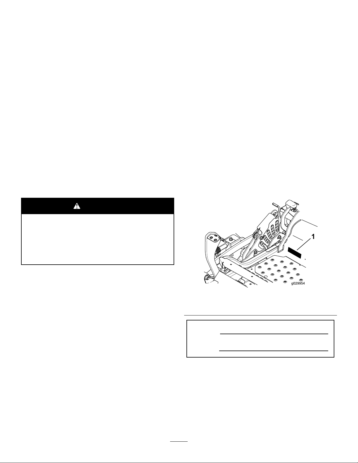
andserialnumbersofyourproductready.Figure1
identiesthelocationofthemodelandserialnumbers
ontheproduct.Writethenumbersinthespace
provided.
WARNING
CALIFORNIA
Proposition65Warning
Theengineexhaustfromthisproduct
containschemicalsknowntotheStateof
Californiatocausecancer,birthdefects,
orotherreproductiveharm.
g029954
Figure1
1.Modelandserialnumberlocation
ModelNo.
SerialNo.
©2018—TheToro®Company
8111LyndaleAvenueSouth
Bloomington,MN55420
Contactusatwww.Toro.com.
2
PrintedintheUSA.
AllRightsReserved
Page 3

Thismanualidentiespotentialhazardsandhas
safetymessagesidentiedbythesafetyalertsymbol
(Figure2),whichsignalsahazardthatmaycause
seriousinjuryordeathifyoudonotfollowthe
recommendedprecautions.
Figure2
1.Safetyalertsymbol
Thismanualuses2wordstohighlightinformation.
Importantcallsattentiontospecialmechanical
informationandNoteemphasizesgeneralinformation
worthyofspecialattention.
Contents
Safety.......................................................................4
SafeOperatingPractices....................................4
ToroMowerSafety..............................................6
SlopeIndicator...................................................8
SafetyandInstructionalDecals..........................9
g000502
ProductOverview...................................................16
Controls...........................................................16
Specications..................................................17
Operation................................................................18
AddingFuel......................................................18
CheckingtheEngine-OilLevel..........................19
BreakinginaNewMachine..............................19
UsingtheRolloverProtectionSystem
(ROPS).........................................................20
EnteringtheUserPosition................................21
ThinkSafetyFirst..............................................21
OperatingtheParkingBrake.............................21
OperatingtheMowerBlade-ControlSwitch
(PTO)............................................................22
OperatingtheThrottle.......................................22
OperatingtheChoke.........................................22
OperatingtheIgnitionSwitch............................23
UsingtheFuelShutoffV alve.............................23
StartingandStoppingtheEngine......................24
UsingtheSafety-InterlockSystem....................25
DrivingForwardorBackward............................26
StoppingtheMachine.......................................27
AdjustingtheHeight-of-Cut...............................27
AdjustingtheAnti-ScalpRollers........................29
AdjustingtheFlowBafeCamLocks................29
PositioningtheFlowBafe................................30
PositioningtheSeat..........................................31
UnlatchingtheSeat..........................................31
AdjustingtheMyRide™Suspension
System..........................................................31
UsingtheDrive-Wheel-ReleaseValves............32
UsingtheSideDischarge.................................33
TransportingtheMachine.................................34
LoadingtheMachine........................................34
OperatingTips.................................................36
Maintenance...........................................................37
RecommendedMaintenanceSchedule(s)...........37
Lubrication..........................................................38
AddingLightOilorSprayLubrication................38
GreasingtheMower.........................................38
LubricatingtheCaster-WheelHubs..................39
EngineMaintenance...........................................40
ServicingtheAirCleaner..................................40
ServicingtheEngineOil....................................41
ServicingtheSparkPlug...................................44
CheckingtheSparkArrester(if
equipped)......................................................45
FuelSystemMaintenance...................................46
ReplacingtheFuelFilter...................................46
ServicingtheFuelT ank.....................................46
ElectricalSystemMaintenance...........................47
3
Page 4

ServicingtheBattery.........................................47
ServicingtheFuses..........................................49
DriveSystemMaintenance..................................49
CheckingtheSeatBelt.....................................49
CheckingtheRolloverProtectionSystem
(ROPS)Knobs..............................................49
AdjustingtheTracking......................................50
CheckingtheTirePressure...............................50
CheckingtheWheelLugNuts...........................51
CheckingtheWheelHubSlottedNut................51
AdjustingtheCaster-PivotBearing...................51
UsingtheClutchShim......................................51
CoolingSystemMaintenance..............................53
CleaningtheEngineScreenandEngine-Oil
Cooler...........................................................53
CleaningtheEngine-CoolingFinsand
Shrouds........................................................53
CheckingandCleaningtheHydraulic-Unit
Shrouds........................................................54
BrakeMaintenance.............................................55
AdjustingtheParkingBrake..............................55
BeltMaintenance................................................56
InspectingtheBelts..........................................56
ReplacingtheMowerBelt.................................56
ReplacingtheHydraulicPump-Drive
Belt................................................................57
ControlsSystemMaintenance.............................58
AdjustingtheControl-HandlePosition..............58
AdjustingtheMotion-ControlLinkage...............59
AdjustingtheMotion-ControlDamper...............60
AdjustingtheMotionControlNeutral-Lock
Pivot..............................................................60
HydraulicSystemMaintenance...........................61
ServicingtheHydraulicSystem........................61
MowerDeckMaintenance....................................63
LevelingtheMowerDeck..................................63
ServicingtheCuttingBlades.............................65
RemovingtheMowerDeck...............................67
ReplacingtheGrassDeector..........................68
Cleaning..............................................................69
CleaningundertheMower................................69
CleaningtheSuspensionSystem.....................69
DisposingofWaste...........................................69
Storage...................................................................70
CleaningandStoringtheMachine....................70
Troubleshooting......................................................71
Schematics.............................................................73
Safety
Improperuseormaintenancebytheoperatoror
ownercanresultininjury.Toreducethepotential
forinjury,complywiththesesafetyinstructions,and
payattentiontothesafetyalertsymbol,whichmeans
Caution,Warning,orDanger—“personalsafety
instruction.”Failuretocomplywiththeinstructions
mayresultinpersonalinjuryordeath.
Important:Thismachinewasmanufactured
accordingtotheappropriateregulatorystandards
ineffectatthetimeofmanufacture.Modifying
thismachineinanywaymaycauseittobe
outofcompliancewiththosestandardsand
withtheinstructionsinthisOperator’sManual.
Modicationstothismachineshouldonlybe
madebyeitherthemanufactureroranAuthorized
ToroDealer.
Thisproductiscapableofamputatinghandsandfeet.
Followallsafetyinstructionstoavoidseriousinjury
ordeath.
Theowner/usercanpreventandisresponsiblefor
accidentsorinjuriesoccurringtopeople,ordamage
toproperty .
Important:Theadditionofattachmentsmadeby
othermanufacturersthatdonotmeetAmerican
NationalStandardsInstitutecerticationwill
causenoncomplianceofthismachine.
SafeOperatingPractices
ThefollowinginstructionsareadaptedfromANSI
standardB71.4-2012.
Training
•ReadtheOperator'sManualandothertraining
material.
Note:Iftheoperator(s)ormechanic(s)cannot
readthemanuallanguage,itistheowner's
responsibilitytoexplainthismaterialtothem.
•Becomefamiliarwiththesafeoperationofthe
equipment,operatorcontrols,andsafetysigns.
•Alloperatorsandmechanicsshouldbetrained.
Theownerisresponsiblefortrainingtheusers.
•Neverletchildrenoruntrainedpeopleoperateor
servicetheequipment.Localregulationsmay
restricttheageoftheoperator.
•Theowner/usercanpreventandisresponsible
foraccidentsorinjuriesoccurringtopeople,or
damagetoproperty.
4
Page 5

Preparation
•Evaluatetheterraintodeterminewhataccessories
andattachmentsareneededtoproperlyand
safelyperformthejob.
Note:Onlyuseaccessoriesandattachments
approvedbythemanufacturer.
•Wearappropriateclothingincluding:ahardhat,
safetyglasses,andhearingprotection.Long
hair,looseclothingorjewelrymaygettangledin
movingparts.
•Inspecttheareawheretheequipmentisused,
andremoveallobjectsthatcanbethrownbythe
machine.
•Checkthatoperator'spresencecontrols,safety
switchesandshieldsareattachedandfunctioning
properly.Donotoperateunlesstheyare
functioningproperly.
Operation
•Lightningcancausesevereinjuryordeath.If
lightningisseen,orthunderisheardinthearea,
donotoperatethemachine;seekshelter.
•Donotrunanengineinanenclosedarea.
•Onlyoperateinwell-litareas,keepingawayfrom
holesandhiddenhazards.
•Ensurethatalldrivesareinneutralandthatthe
parkingbrakeisengagedbeforestartingengine.
Onlystarttheenginefromtheoperator’sposition.
•Makesurethatyouhavegoodtractionwhileusing
thismachine,especiallywhenbackingup.Never
operateonwetgrass.Reducedtractioncould
causeslipping.
•Slowdownanduseextracareonhillsides.Be
suretotravelsidetosideonhillsides.Turf
conditionscanaffectthestabilityofthemachine.
Usecautionwhileoperatingneardrop-offs.
•Slowdownandusecautionwhenmakingturns
andwhenchangingdirectionsonslopes.
•Donotraisethemowerdeckwiththeblades
running.
•DonotoperatethemachinewithoutthePTO
shieldorotherguardssecurelyinplace.Besure
allinterlocksareattached,adjustedproperly,and
functioningproperly.
•Donotoperatewiththedischargedeectorraised,
removedoraltered,unlessusingagrasscatcher.
•Donotchangetheenginegovernorsettingor
overspeedtheengine.
•Stoponlevelground,disengagedrives,engage
theparkingbrake(ifprovided),shutoffthe
enginebeforeleavingtheoperator'spositionfor
anyreason,includingemptyingthecatchersor
uncloggingthechute.
•Stopequipmentandinspectthebladesafter
strikingobjectsorifanabnormalvibrationoccurs.
Makethenecessaryrepairsbeforeresuming
operations.
•Keepyourhandsandfeetawayfromthecutting
unit.
•Lookbehindanddownbeforebackingupto
ensureaclearpath.
•Keeppetsandbystandersawayfromanoperating
machine.
•Slowdownandusecautionwhenmakingturns
andcrossingroadsandsidewalks.Stopthe
bladesifyouarenotmowing.
•Beawareofthemower-dischargedirectionand
donotpointitatanyone.
•Donotoperatethemowerundertheinuenceof
alcoholordrugs.
•Usecarewhenloadingorunloadingthemachine
intoorfromatrailerortruck.
•Usecarewhenapproachingblindcorners,shrubs,
trees,orotherobjectsthatmayobscurevision.
SafeHandlingofFuels
•Toavoidpersonalinjuryorpropertydamage,use
extremecareinhandlinggasoline.Gasolineis
extremelyammableandthevaporsareexplosive.
•Extinguishallcigarettes,cigars,pipes,andother
sourcesofignition.
•Useonlyanapprovedfuelcontainer.
•Donotremovethefuelcaporaddfuelwiththe
enginerunning.
•Allowtheenginetocoolbeforefueling.
•Donotrefuelthemachineindoors.
•Donotstorethemachineorfuelcontainerwhere
thereisanopename,spark,orpilotlightsuchas
onawaterheateroronotherappliances.
•Donotllcontainersinsideavehicle,onatruck,
oronatrailerbedwithaplasticliner.Alwaysplace
containersonthegroundawayfromyourvehicle
beforelling.
•Removeequipmentfromthetruckortrailerand
fuelitontheground.Ifthisisnotpossible,
thenaddfuelwithsuchequipmentasaportable
container,ratherthanfromafueldispensernozzle.
•Keepthenozzleincontactwiththerimofthefuel
tankorcontaineropeningatalltimesuntilfueling
iscomplete.
•Donotuseanozzlelockopendevice.
•Iffuelisspilledonclothing,changeyourclothing
immediately.
•Donotoverllfueltank.Replacefuelcapand
tightensecurely.
5
Page 6

MaintenanceandStorage
•Disengagedrives,settheparkingbrake,stop
theengine,andremovethekeyordisconnect
spark-plugwire.Waitforallmovementtostop
beforeadjusting,cleaning,orrepairing.
•Parkthemachineonalevelsurface.
•Cleangrassanddebrisfromthecuttingunit,
drives,mufers,andenginetohelppreventres.
•Cleanupoilorfuelspillage.
•Lettheenginecoolbeforestoring.
•Donotstorefuelnearamesordrainindoors.
•Donotallowuntrainedpersonneltoservice
machine.
•Usejackstandstosupportcomponentswhen
required.
•Carefullyreleasepressurefromcomponentswith
storedenergy.
•Disconnectthebatteryorremovethespark-plug
wirebeforemakinganyrepairs.Disconnectthe
negativeterminalrstandthepositiveterminal
last.Reconnectthepositiverstandnegativelast.
•Usecarewhencheckingtheblades.Wrapthe
blade(s)orwearthicklypaddedgloves,anduse
cautionwhenservicingthem.Onlyreplaceblades;
donotstraightenorweldthem.
•Keephandsandfeetawayfrommovingparts.If
possible,donotmakeadjustmentswiththeengine
running.
•Keepallpartsingoodworkingconditionandall
hardwaretightened.Replaceallwornordamaged
decals.
Hauling
•Usecarewhenloadingorunloadingthemachine
intoatraileroratruck.
•Usefull-widthrampsforloadingmachineintoa
traileroratruck.
•Tiethemachinedownsecurelyusingstraps,
chains,cable,orropes.Bothfrontandrearstraps
shouldbedirecteddownandoutwardfromthe
machine.
ToroMowerSafety
Thefollowinglistcontainssafetyinformationspecic
toToroproductsandothersafetyinformationyou
mustknow.
Thisproductiscapableofamputatinghandsand
feet,andthrowingobjects.Alwaysfollowallsafety
instructionstoavoidseriousinjuryordeath.
Thisproductisdesignedforcuttingandrecycling
grass,or,whenequippedwithagrassbagger,for
catchingcutgrass.Anyuseforpurposesother
thanthesecouldprovedangeroustotheuserand
bystanders.
GeneralOperation
•Besurethattheareaisclearofbystandersbefore
mowing.Stopthemachineifanyoneentersthe
area.
•Donottouchequipmentorattachmentpartswhich
maybehotfromoperation.Allowalloftheparts
tocoolbeforeattemptingtomaintain,adjust,or
servicethemachine.
•UseonlyT oro-approvedattachments.Warranty
maybevoidedifusedwithanyunapproved
attachments.
•Checkcarefullyforoverheadclearances(i.e.
branches,doorways,electricalwires,etc.)before
operatingunderanyobjects,anddonotcontact
them.
•Slowdownbeforemakingturnsanduseextra
caution.
•Usecautionwhenridingtheplatformovercurbs,
rocks,roots,orotherobstructions.
•Lookbehindanddownbeforebackinguptoensure
aclearpath.Useextracarewhenoperatingin
reverse.
•Donotjerkthecontrols;useasteadymotion.
•Whenloadingorunloadingthemachine,useone
full-widthrampthatiswideenoughtoextend
beyondthewidthofthemachine.
•Donotcarrypassengers.
•Donotcarryequipmentonthemachine.
SlopeOperation
Allslopesandrampsrequireextracaution.Ifyoufeel
uneasyonaslope,donotmowit.
•Removeobstaclessuchasrocks,treelimbs,etc.
fromthemowingarea.
•Watchforholes,rutsorbumps.
Note:T allgrasscanhideobstacles.
•Usecautionneardrop-offs,ditches,or
embankments.
6
Page 7

Note:Themachinecouldsuddenlyturnoverifa
wheelgoesovertheedgeofaclifforditch,orif
anedgecavesin.
•Useextracarewithgrasscatchersorother
attachments.
Note:Thesecanchangethestabilityofthe
machine.
•Keepallmovementonslopesslowandgradual.
•Donotmakesuddenchangesinspeedor
direction.
•Mowslopessidetoside.
•Donotmowslopesgreaterthan15degrees.
UsingtheRolloverProtection System(ROPS)
•TheROPSisanintegralandeffectivesafety
device.KeeptheROPSintheraisedandlocked
positionandusetheseatbeltwhenoperatingthe
machine.
Service
•Donotstorethemachineorafuelcontainerinside
wherethereisanopename,suchasneara
waterheaterorfurnace.
•Keepthenutsandboltstight,especiallythe
blade-attachmentbolts.
•Neverinterferewiththeintendedfunctionofa
safetydeviceorreducetheprotectionprovided
byasafetydevice.Checktheirproperoperation
regularly.
•Tobestprotectyourinvestmentandmaintain
optimalperformanceofyourToroequipment,count
onT orogenuineparts.Whenitcomestoreliability,
Torodeliversreplacementpartsdesignedtothe
exactengineeringspecicationsofourequipment.
Forpeaceofmind,insistonT orogenuineparts.
•Checkbrakeoperationfrequently.Adjustand
serviceasrequired.
•LowertheROPStemporarilyonlywhenabsolutely
necessary.Donotweartheseatbeltwhenthe
ROPSisfoldeddown.
•Beawarethereisnorolloverprotectionwhenthe
ROPSisinthedownposition.
•Becertainthattheseatbeltcanbereleased
quicklyintheeventofanemergency.
•Checktheareatobemowedandneverfolddown
theROPSinareaswherethereareslopes,drop
offsorwater.
•Checkcarefullyforoverheadclearances(i.e.
branches,doorways,electricalwires)before
drivingunderanyobjectsanddonotcontactthem.
•KeeptheROPSinsafeoperatingconditionby
periodicallythoroughlyinspectingfordamageand
keepingallmountingfastenerstight.
•ReplaceadamagedROPS.Donotrepairor
revise.
•DonotremovetheROPS.
•AnyalterationstoaROPSmustbeapprovedby
themanufacturer.
7
Page 8
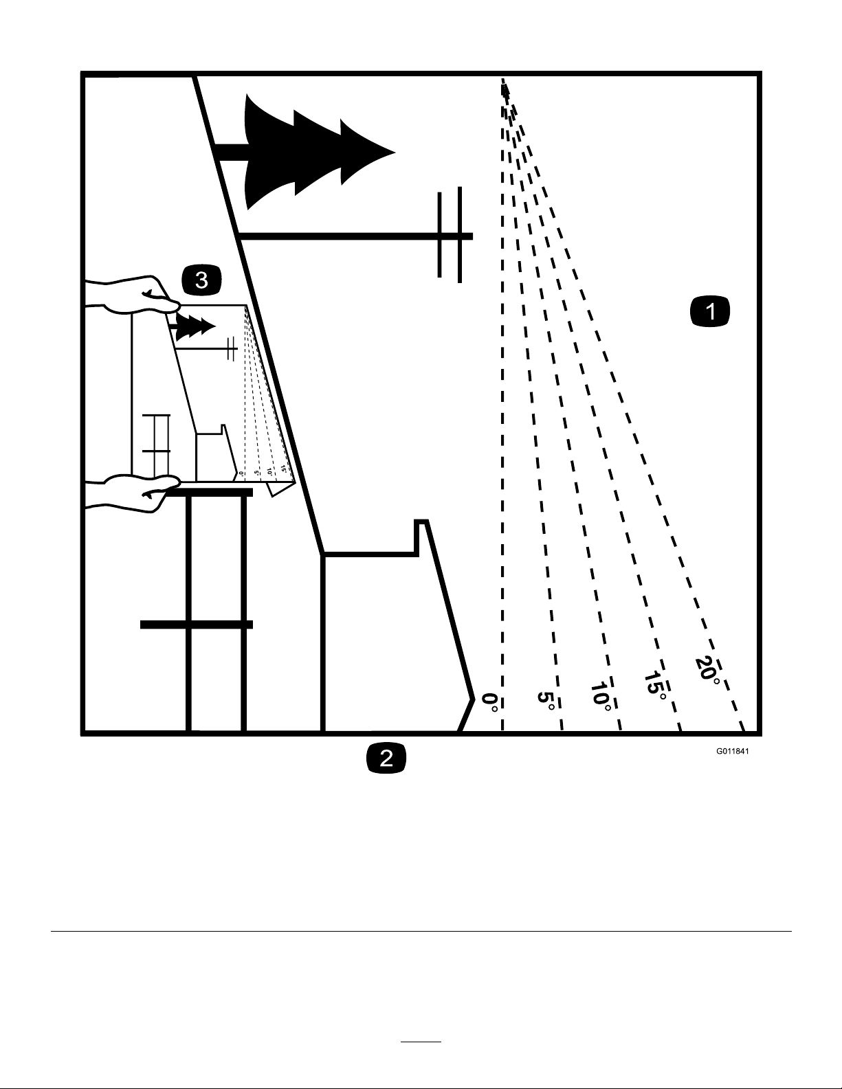
SlopeIndicator
Figure3
Thispagemaybecopiedforpersonaluse.
1.Themaximumslopeyoucansafelyoperatethemachineonis15degrees.Usetheslopecharttodeterminethedegreeofslope
ofhillsbeforeoperating.Donotoperatethismachineonaslopegreaterthan15degrees.Foldalongtheappropriateline
tomatchtherecommendedslope.
2.Alignthisedgewithaverticalsurface,atree,building,fencepole,etc.
3.Exampleofhowtocompareslopewithfoldededge.
8
g011841
Page 9
SafetyandInstructionalDecals
Safetydecalsandinstructionsareeasilyvisibletotheoperatorandarelocatednearanyarea
ofpotentialdanger.Replaceanydecalthatisdamagedorlost.
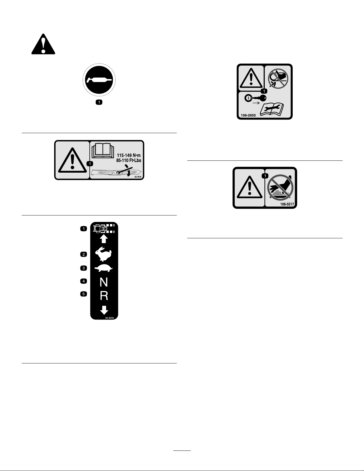
58-6520
1.Grease
93-7818
decal58-6520
decal106-2655
106–2655
1.Warning-donottouchorapproachmovingbelts;remove
theignitionkeyandreadtheinstructionsbeforeservicing
orperformingmaintenance.
decal93-7818
1.Warning—readtheOperator'sManualforinstructionson
torquingthebladebolt/nutto115-149N-m(85-110ft-lb).
99-8936
1.Machinespeed4.Neutral
2.Fast5.Reverse
3.Slow
decal106-5517
106-5517
1.Warning–Donottouchthehotsurface.
decal99-8936
9
Page 10
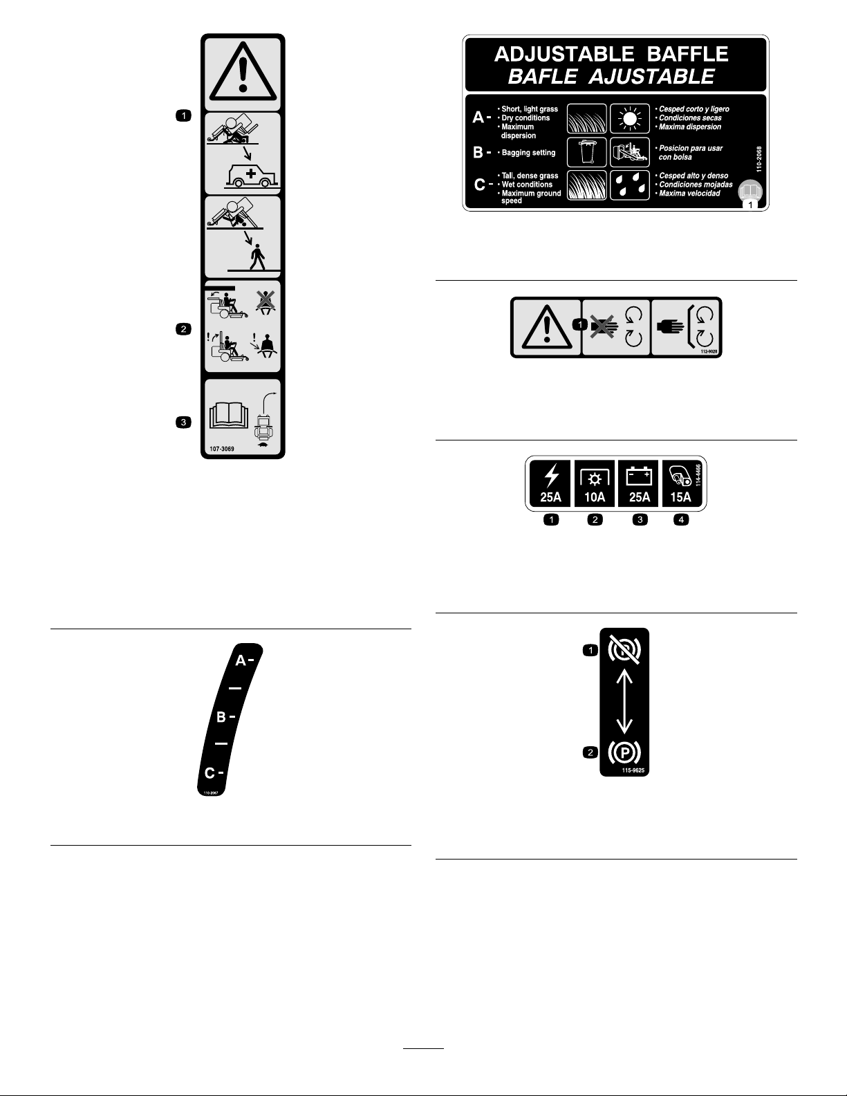
decal107-3069
107-3069
1.Warning–thereisnorolloverprotectionwhentherollbaris
down.
2.Toavoidinjuryordeathfromarolloveraccident,keepthe
rollbarinthefullyraisedandlockedpositionandwear
theseatbelt.Lowertherollbaronlywhenabsolutely
necessary;donotwearthetheseatbeltwhentherollbaris
down.
3.ReadtheOperator'sManual;driveslowlyandcarefully.
decal110-2068
110-2068
1.ReadtheOperator'sManual.
decal112-9028
112-9028
1.Warning—stayawayfrommovingparts;keepallguardsin
place.
decal114-4466
114-4466
1.Main,25A
2.PTO,10A
3.Charge,25A
4.Auxiliary,15A
decal115-9625
decal110-2067
110-2067
1.Parking
115-9625
2.Parkingbrake—engaged
brake—disengaged
10
Page 11
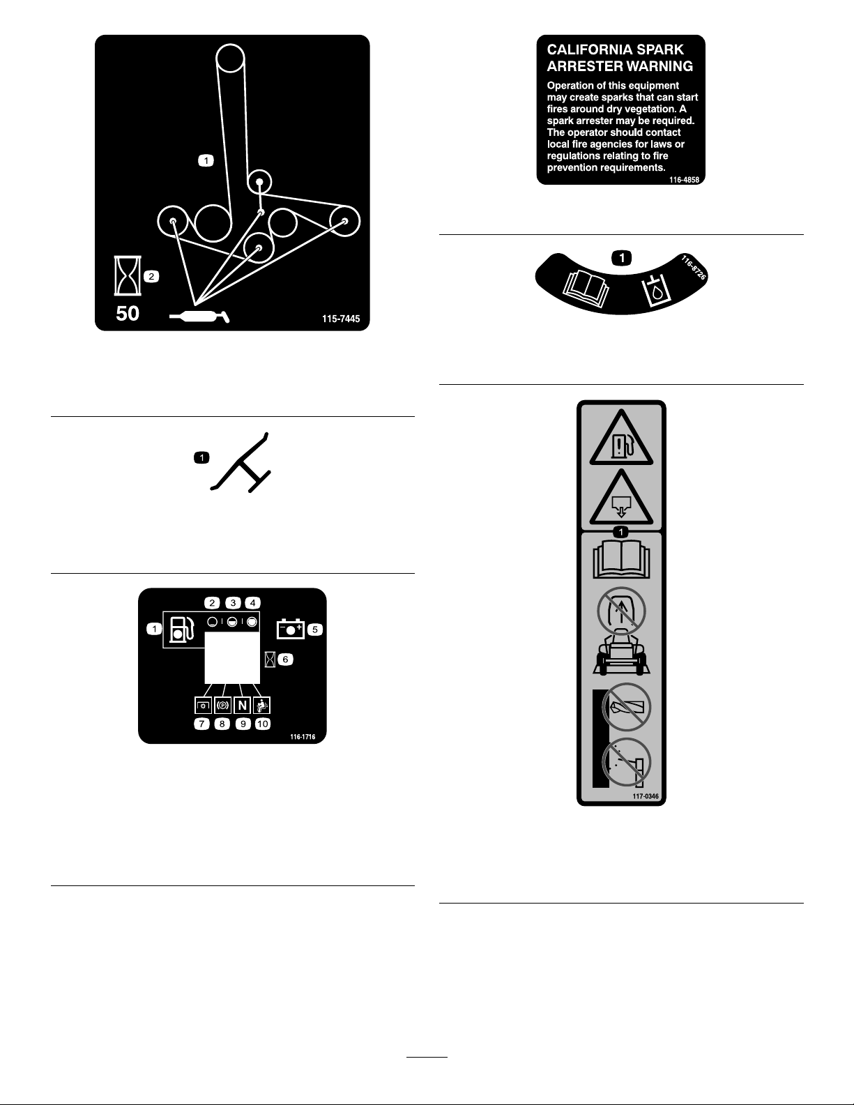
115-7445
1.Greasepulleysandspindles
2.Maintenanceinterval—50hours
Manufacturer'sMark
1.Indicatesthebladeisidentiedasapartfromtheoriginal
machinemanufacturer.
decal116-4858
116-4858
decal116-8726
decal115-7445
1.ReadtheOperator’sManualforrecommendedhydrooil.
decaloemmarkt
116-8726
116-1716
1.Fuel6.Hourmeter
2.Empty
3.Half
4.Full9.Neutral
5.Battery
7.PTO
8.Parkingbrake
10.Operatorpresenceswitch
decal116-1716
decal117-0346
117-0346
1.Fuelleakhazard—readtheOperator'sManual;donot
attempttoremovetherollbar;donotweld,drillormodify
therollbarinanyway.
11
Page 12
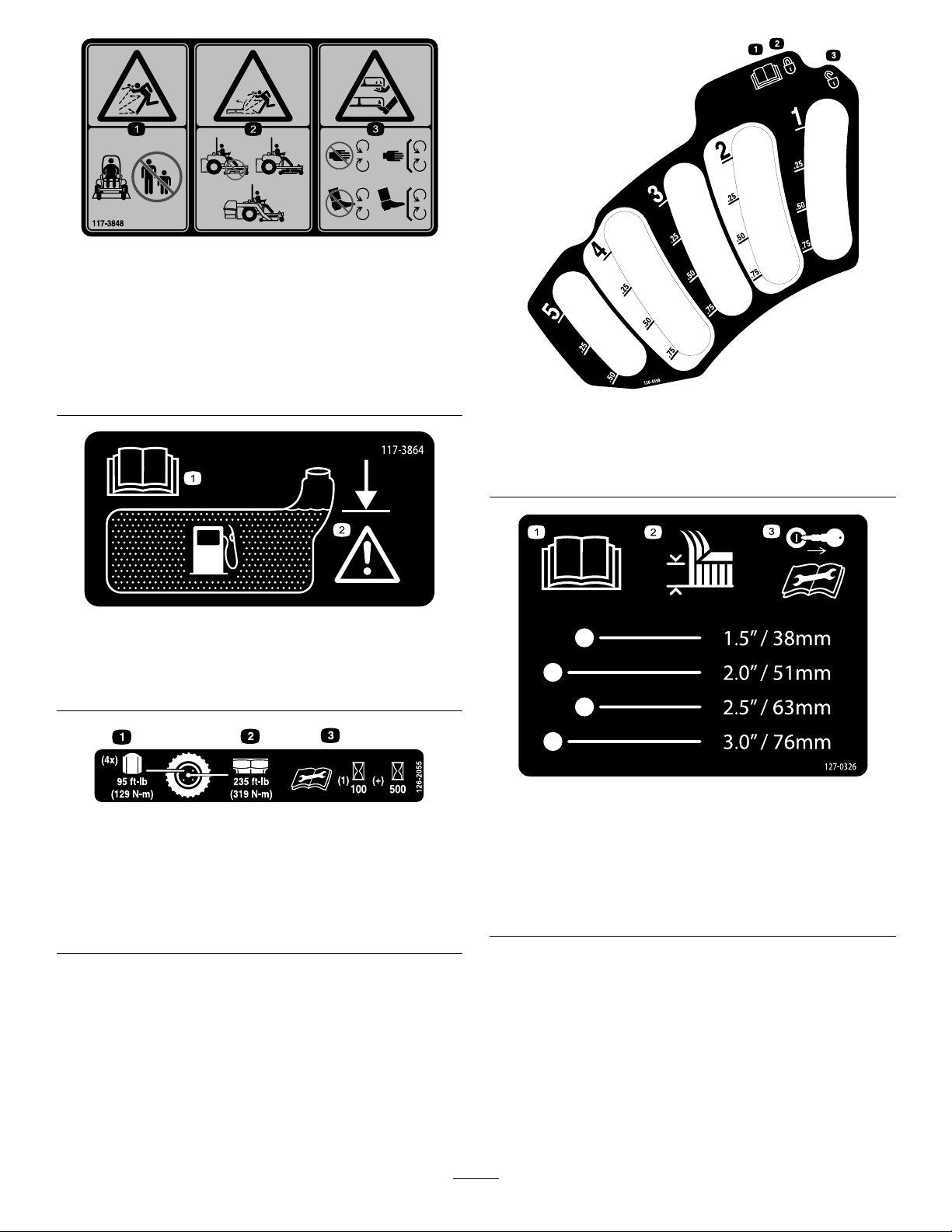
117-3848
1.Thrownobjecthazard—keepbystandersasafedistance
fromthemachine
2.Thrownobjecthazard,mower-donotoperatewithoutthe
deector,dischargecoverorgrasscollectionsystemin
place.
3.Cutting/dismembermentofhandorfoot—stayawayfrom
movingparts;keepallguardsandshieldsinplace.
decal117-3848
decal126-4398
126-4398
117-3864
1.ReadtheOperator’s
Manual.
2.Filltobottomofllerneck;
warning—donotoverll
thetank.
126-2055
1.Wheellugnuttorque95ft-lb(129N-m)(4x)
2.Wheelhubnuttorque235ft-lb(319N-m)
3.ReadandunderstandtheOperator’smanualbefore
performinganymaintenance,checktorqueafterrst100
hoursthenevery500hoursthereafter.
1.ReadtheOperator’s
3.Unlock
manual
2.Lock
decal117-3864
decal127-0326
decal126-2055
1.ReadtheOperator's
Manual.
127-0326
3.Removethekeyfrom
theignitionandreadthe
Operator'sManualbefore
performingmaintenance
orservicingthemachine.
2.Height-of-cut
12
Page 13

BatterySymbols
Someorallofthesesymbolsareonyourbattery
decalbatterysymbols
1.Explosionhazard
2.Nore,opename,or
6.Keepbystandersasafe
7.Weareyeprotection;
smoking.
3.Causticliquid/chemical
8.Batteryacidcancause
burnhazard
4.Weareyeprotection9.Flusheyesimmediately
5.ReadtheOperator's
10.Containslead;donot
Manual.
distancefromthebattery.
explosivegasescan
causeblindnessandother
injuries
blindnessorsevereburns.
withwaterandgetmedical
helpfast.
discard.
decal132-5063
132-5063
1.Camlock2.Camunlock
decal132-5067
132–5067
120-5897
1.Choke4.Slow
2.Fast
3.Continuousvariable
setting
decal120-5897
5.Powertake-off(PTO),
Bladecontrolswitch
13
Page 14
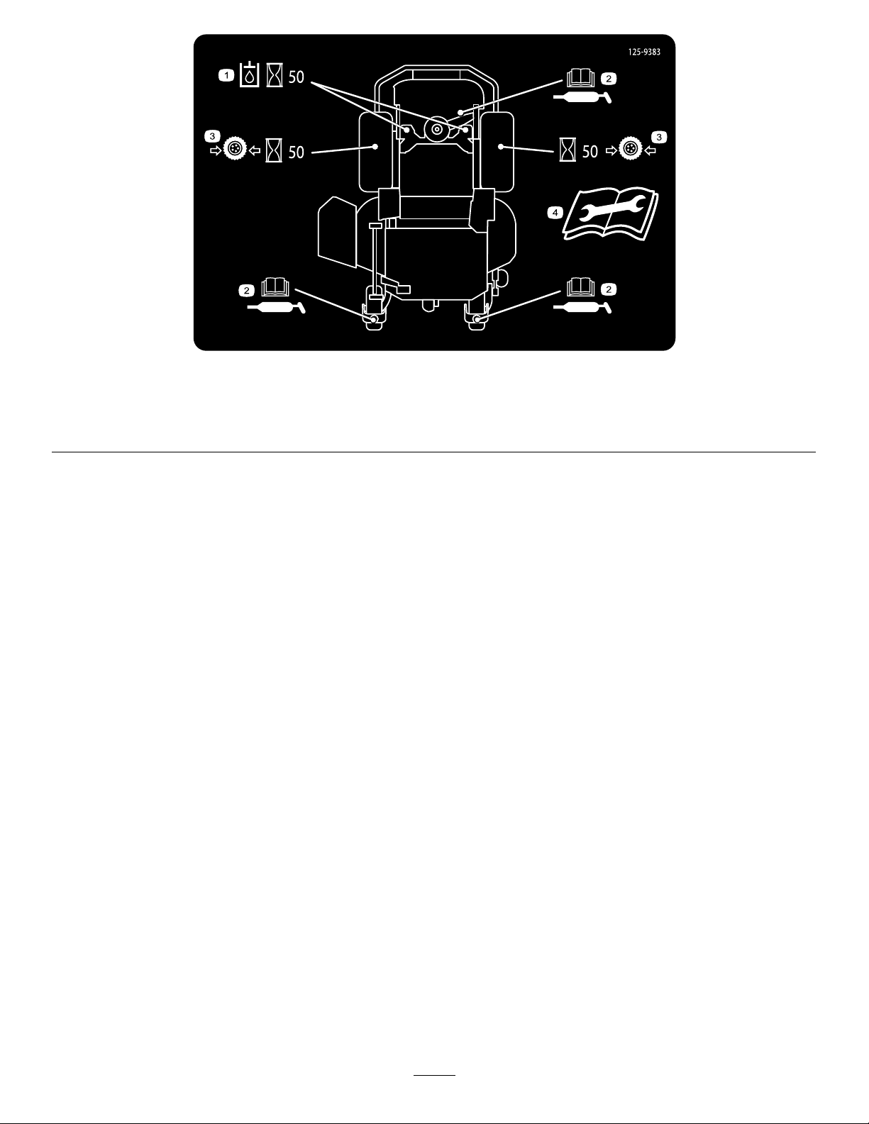
125–9383
1.Checkhydraulicoilevery50operatinghours.3.Checkthetirepressureevery50operatinghours.
2.ReadtheOperator’sManualforinformationonlubricating
themachine.
4.ReadtheOperator’sManualbeforeservicingorperforming
maintenance.
decal125-9383
14
Page 15
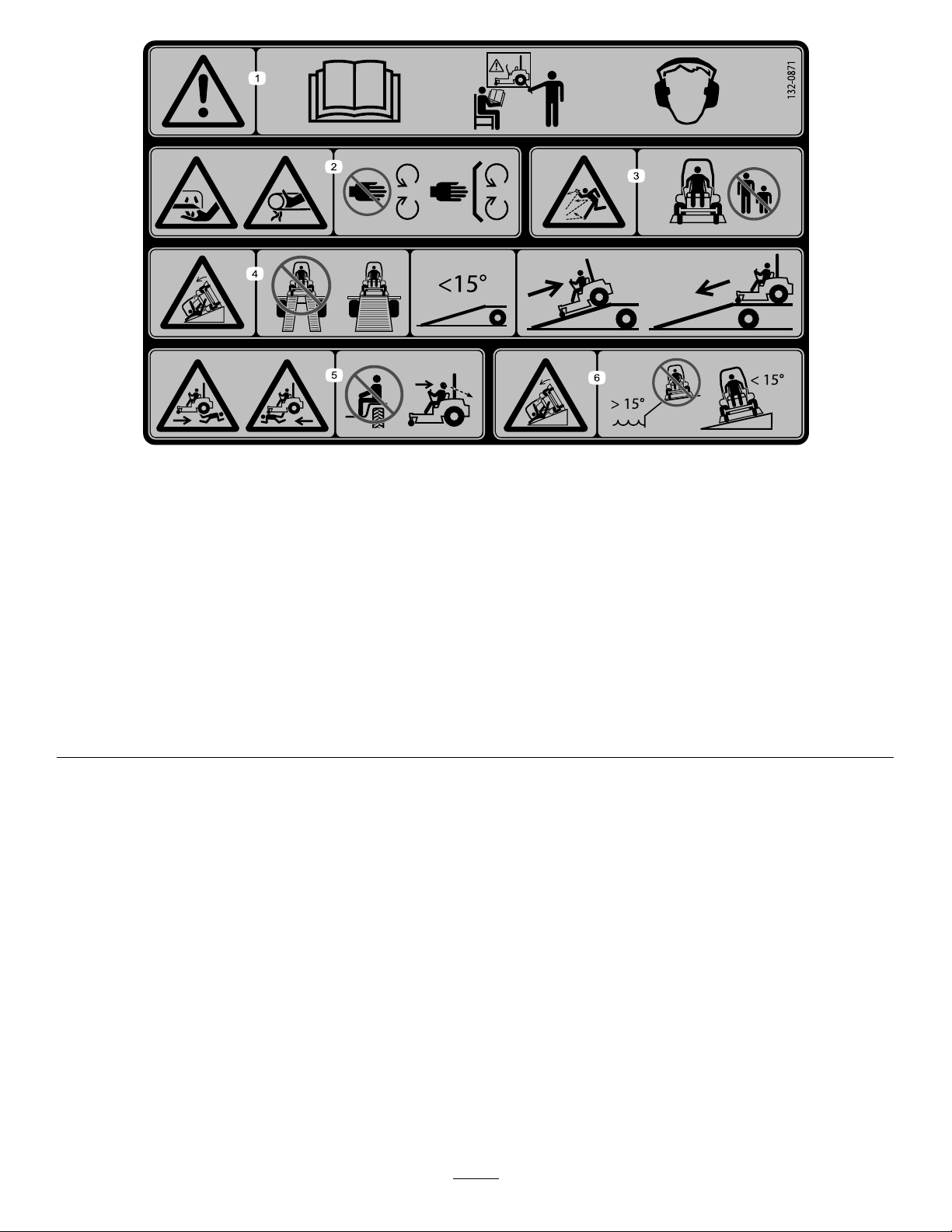
132-0871
Note:Thismachinecomplieswiththeindustrystandardstabilitytestinthestaticlateralandlongitudinaltestswiththemaximum
recommendedslopeindicatedonthedecal.ReviewtheinstructionsforoperatingthemachineonslopesintheOperator’sManualas
wellastheconditionsinwhichyouwouldoperatethemachinetodeterminewhetheryoucanoperatethemachineinthoseconditions
onthatdayandatthatsite.Changesintheterraincanresultinachangeinslopeoperationforthemachine.Ifpossible,keepthe
cuttingunitsloweredtothegroundwhileoperatingthemachineonslopes.Raisingthecuttingunitswhileoperatingonslopescan
causethemachinetobecomeunstable.
decal132-0871
1.Warning—readtheOperator’sManual;donotoperatethis
machineunlessyouaretrained;wearhearingprotection.
2.Cutting,dismembering,andentanglementhazard—keep
handsawayfrommovingparts;keepallguardsandshieldsin
place.
3.Thrownobjecthazard—keepbystandersaway.6.Tippinghazardonslopes—donotuseonslopesnearopen
4.Ramphazard—whenloadingontoatrailer ,donotusedual
ramps;onlyuseasingularrampwideenoughforthemachine
andthathasaninclinelessthan15°;backuptheramp(in
reverse)anddriveforwardofftheramp.
5.Bodilyharmhazard—donotcarrypassengers;lookbehind
youwhenmowinginreverse.
water;donotuseonslopesgreaterthan15°.
15
Page 16
ProductOverview
HourMeter
Thehourmeterrecordsthenumberofhoursthe
enginehasoperated.Itoperateswhentheengine
isrunning.Usethesetimesforschedulingregular
maintenance(Figure6).
FuelGauge
Thefuelgaugeislocatedwiththehourmeter,and
thebarslightupwhentheignitionswitchisintheOn
position(Figure6).
Theindicatorlightappearswhenthefuellevelislow
(approximatelyonegallonremaininginthefueltank).
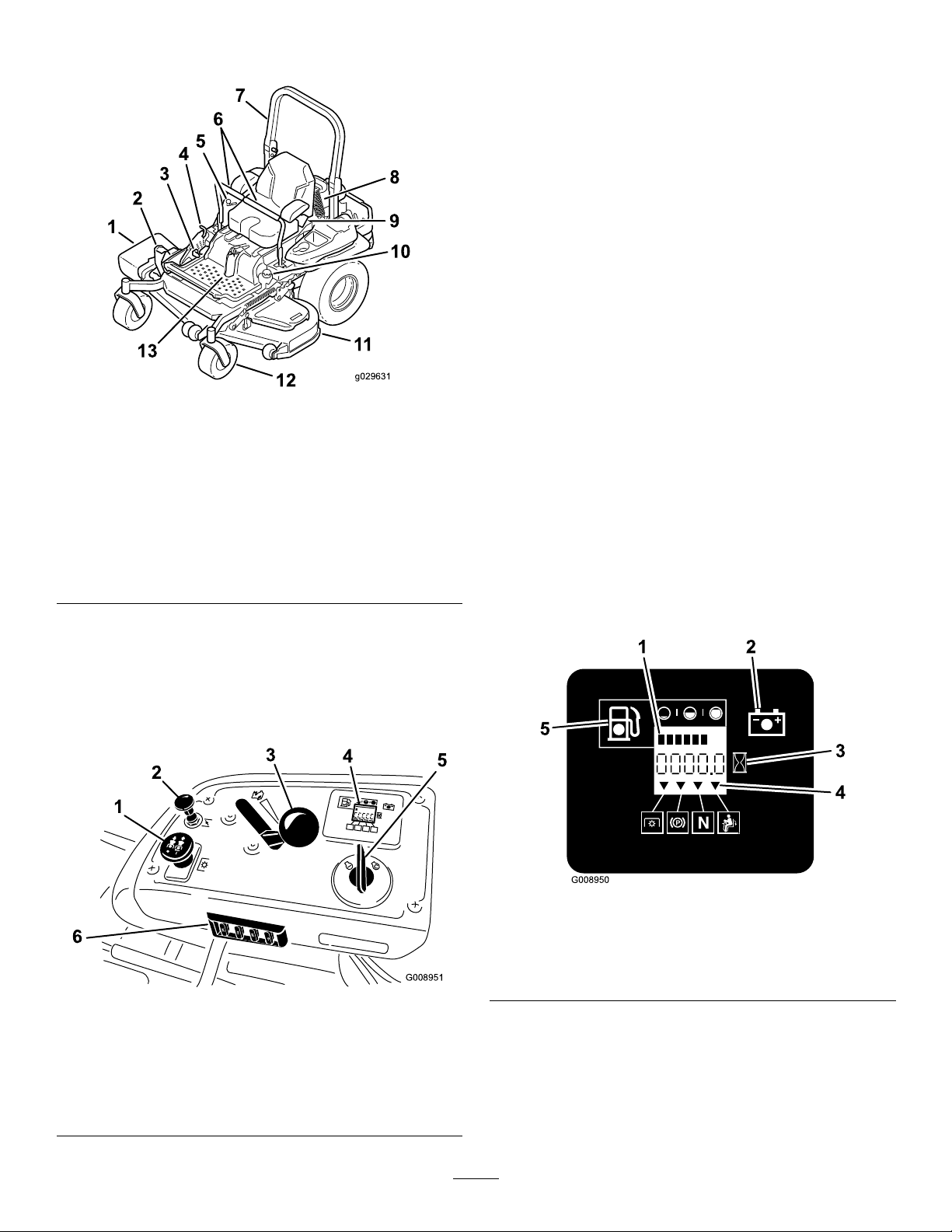
Safety-InterlockIndicators
Figure4
1.Side-dischargedeector
2.Height-of-cutdeck-lift
pedal
3.Parking-brakelever10.Fuelcap
4.Transportlock11.Mowerdeck
5.Controls12.Casterwheel
6.Motion-controllevers13.Front,shockassembly
7.Rollbar
8.Rear,shockassembly
9.Seatbelt
Controls
Becomefamiliarwithallthecontrolsbeforeyoustart
theengineandoperatethemachine(Figure4and
Figure5).
g029631
Therearesymbolsonthehourmeter,andtheindicate
withablacktrianglethattheinterlockcomponentisin
thecorrectposition(Figure6).
Battery-IndicatorLight
IftheignitionkeyisturnedtotheOnpositionforafew
seconds,thebatteryvoltagewillbedisplayedinthe
areawherethehoursarenormallydisplayed.
Thebatterylightturnsonwhentheignitionisturned
onandwhenthechargeisbelowthecorrectoperating
level(Figure6).
Figure5
1.PTOSwitch
2.Choke
3.Throttlecontrol6.Fuses
4.Hour
5.Ignitionswitch
g008950
Figure6
1.Fuelgauge(bars)4.Safety-interlocksymbols
2.Batterylight
3.Hourmeter
g008951
meter/Safety-interlock
display
ThrottleControl
ThethrottlecontrolisvariablebetweenFastand
5.Lowfuel-indicatorlight
Slow.
16
Page 17

Choke
Neutral-LockPosition
Usethechoketostartacoldengine.Pullthechoke
knobuptoengageit.
Blade-ControlSwitch(PTO)
Theblade-controlswitch(PTO)isusedtoengage
theelectricclutchanddrivethemowerblades.Pull
theswitchuptoengagethebladesandrelease.To
disengagetheblades,pushtheblade-controlswitch
(PTO)downormoveamotion-controlleverintothe
neutral-lockposition.
IgnitionSwitch
Thisswitchisusedtostartthemowerengineandhas
3positions:Start,RunandOff.
Motion-ControlLevers
Themotion-controlleversareusedtodrivethe
machineforward,reverse,andturneitherdirection.
Theneutral-lockpositionisusedwiththe
safety-interlocksystemtoengageandtodetermine
theneutralposition.
FuelShutoffValve
Closethefuelshutoffvalve(undertheseat)when
transportingorstoringthemower.
Attachments/Accessories
AselectionofT oroapprovedattachmentsand
accessoriesisavailableforusewiththemachineto
enhanceandexpanditscapabilities.Contactyour
AuthorizedServiceDealerorDistributororgoto
www.T oro.comforalistofallapprovedattachments
andaccessories.
Specications
Note:Specicationsanddesignaresubjecttochangewithoutnotice.
Width:
60-inchDeck72-inchDeck
WithoutDeck
DeectorUp157cm(62inches)187cm(74inches)
DeectorDown192cm(76inches)222cm(88inches)
Length:
RollBar-Up
RollBar-Down
Height:
RollBar-UpRollBar-Down
179cm(71inches)119cm(47inches)
Weight:
135cm(53inches)150cm(59inches)
60-inchDeck72-inchDeck
211cm(83inches)219cm(86inches)
215cm(85inches)223cm(88inches)
ModelWeight
74992
74993
608kg(1340lb)
640kg(1410lb)
17
Page 18

Operation
Note:Determinetheleftandrightsidesofthe
machinefromthenormaloperatingposition.
AddingFuel
•Forbestresults,useonlyclean,fresh(lessthan
30daysold),unleadedgasolinewithanoctane
ratingof87orhigher((R+M)/2ratingmethod).
•Ethanol:Gasolinewithupto10%ethanol
(gasohol)or15%MTBE(methyltertiarybutyl
ether)byvolumeisacceptable.Ethanoland
MTBEarenotthesame.Gasolinewith15%
ethanol(E15)byvolumeisnotapprovedforuse.
Neverusegasolinethatcontainsmorethan
10%ethanolbyvolume,suchasE15(contains
15%ethanol),E20(contains20%ethanol),orE85
(containsupto85%ethanol).Usingunapproved
gasolinemaycauseperformanceproblemsand/or
enginedamagewhichmaynotbecoveredunder
warranty.
•Donotusegasolinecontainingmethanol.
•Donotstorefueleitherinthefueltankorfuel
containersoverthewinterunlessafuelstabilizer
isused.
•Donotaddoiltogasoline.
DANGER
DANGER
Incertainconditionsduringfueling,static
electricitycanbereleasedcausingaspark
whichcanignitethegasolinevapors.Are
orexplosionfromgasolinecanburnyouand
othersandcandamageproperty.
•Alwaysplacegasolinecontainersonthe
groundawayfromyourvehiclebefore
lling.
•Donotllgasolinecontainersinsidea
vehicleoronatruckortrailerbedbecause
interiorcarpetsorplastictruckbedliners
mayinsulatethecontainerandslowthe
lossofanystaticcharge.
•Whenpractical,removegas-powered
equipmentfromthetruckortrailerand
refueltheequipmentwithitswheelsonthe
ground.
•Ifthisisnotpossible,thenrefuelsuch
equipmentonatruckortrailerfroma
portablecontainer,ratherthanfroma
gasolinedispensernozzle.
•Ifagasolinedispensernozzlemustbe
used,keepthenozzleincontactwiththe
rimofthefueltankorcontaineropeningat
alltimesuntilfuelingiscomplete.
Incertainconditions,gasolineisextremely
ammableandhighlyexplosive.Areor
explosionfromgasolinecanburnyouand
othersandcandamageproperty.
•Fillthefueltankoutdoors,inanopenarea,
whentheengineiscold.Wipeupany
gasolinethatspills.
•Neverllthefueltankinsideanenclosed
trailer.
•Donotllthefueltankcompletelyfull.Add
gasolinetothefueltankuntilthelevelis6
to13mm(1/4to1/2inch)belowthebottom
ofthellerneck.Thisemptyspaceinthe
tankallowsgasolinetoexpand.
•Neversmokewhenhandlinggasoline,and
stayawayfromanopenameorwhere
gasolinefumesmaybeignitedbyaspark.
•Storegasolineinanapprovedcontainer
andkeepitoutofthereachofchildren.
Neverbuymorethana30-daysupplyof
gasoline.
•Donotoperatewithoutentireexhaust
systeminplaceandinproperworking
condition.
WARNING
Gasolineisharmfulorfatalifswallowed.
Long-termexposuretovaporscancause
seriousinjuryandillness.
•Avoidprolongedbreathingofvapors.
•Keepfaceawayfromnozzleandgastank
orconditionerbottleopening.
•Avoidcontactwithskin;washoffspillage
withsoapandwater.
UsingStabilizer/Conditioner
Useafuelstabilizer/conditionerinthemachineto
providethefollowingbenets:
•Keepsgasolinefreshduringstorageof90daysor
less.Forlongerstorageitisrecommendedthat
thefueltankbedrained.
•Cleanstheenginewhileitruns
•Eliminatesgum-likevarnishbuildupinthefuel
system,whichcauseshardstarting
Important:Donotusefueladditives
containingmethanolorethanol.
18
Page 19
Addthecorrectamountofgasstabilizer/conditioner
tothegas.
Note:Afuelstabilizer/conditionerismosteffective
whenmixedwithfreshgasoline.T ominimizethe
chanceofvarnishdepositsinthefuelsystem,use
fuelstabilizeratalltimes.
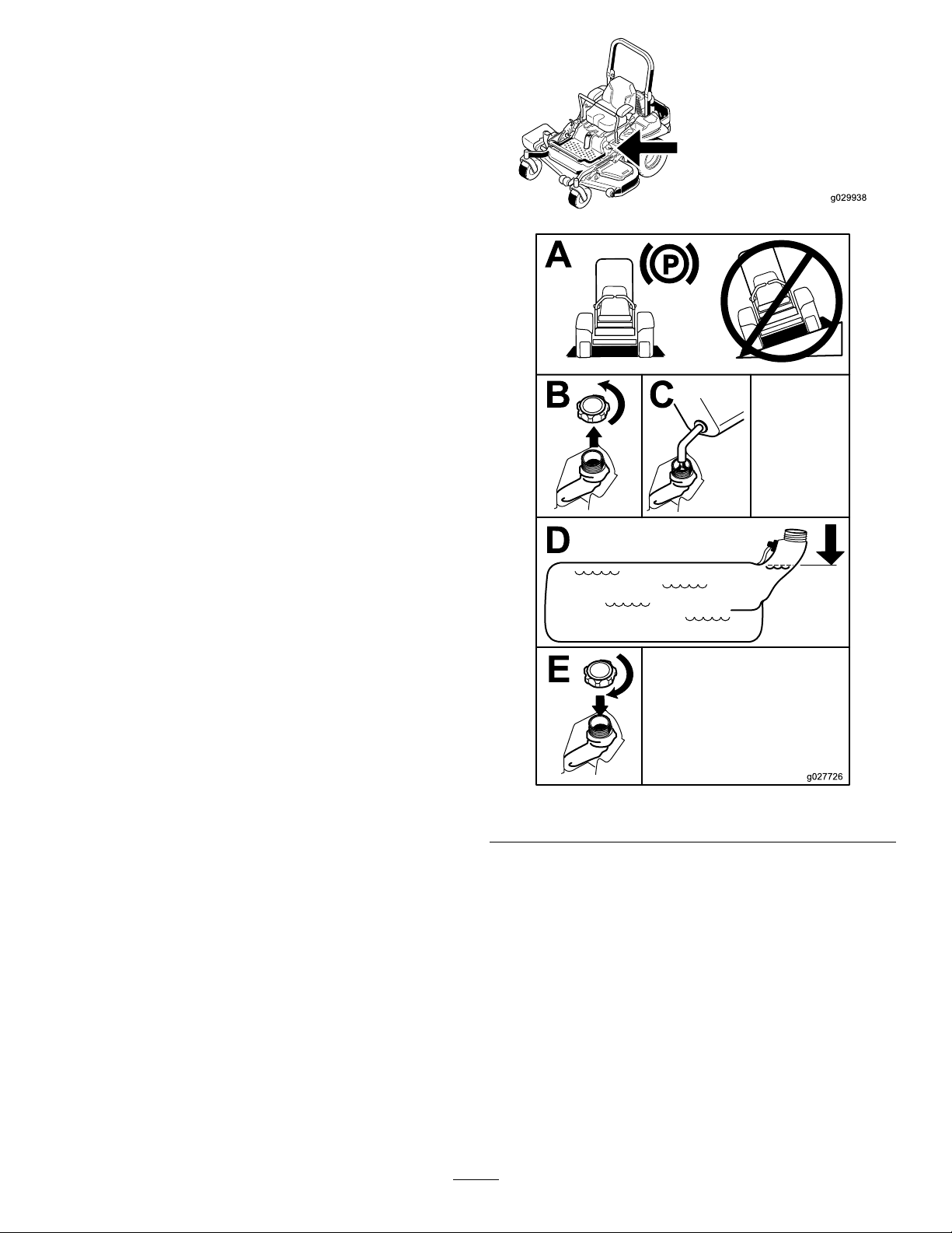
FillingtheFuelTank
Note:Donotllthefueltankcompletelyfull.Fillthe
fueltanktothebottomofthellerneck.Theempty
spaceinthetankallowsthegasolinetoexpand.
1.Parkthemachineonlevelground.
2.Shuttheengineoffandsettheparkingbrake.
3.Cleanaroundthefuel-tankcap.
4.Fillthefueltanktothebottomofthellerneck
(Figure7).
Note:Ensurethatthereisemptyspaceinthe
tanktoallowthegasolinetoexpand
g029938
Figure7
CheckingtheEngine-Oil Level
Beforeyoustarttheengineandusethemachine,
checktheoillevelintheenginecrankcase;referto
CheckingtheEngine-OilLevel(page19).
BreakinginaNewMachine
Newenginestaketimetodevelopfullpower.Mower
decksanddrivesystemshavehigherfrictionwhen
new,placingadditionalloadontheengine.Allow
19
g027726
Page 20
40to50hoursofbreak-intimefornewmachinesto
developfullpowerandbestperformance.
UsingtheRollover ProtectionSystem(ROPS)
WARNING
Toavoidinjuryordeathfromrollover:keep
therollbarinthefullyraisedlockedposition
andusetheseatbelt.
Ensuretheseatissecuredtothemachine.
WARNING
Thereisnorolloverprotectionwhentheroll
barisinthedownposition.
•Lowertherollbaronlywhenabsolutely
necessary.
•Donotweartheseatbeltwhentherollbar
isinthedownposition.
•Driveslowlyandcarefully.
•Raisetherollbarassoonasclearance
permits.
•Checkcarefullyforoverheadclearances
(i.e.branches,doorways,electricalwires)
beforedrivingunderanyobjectsanddo
notcontactthem.
Important:Lowertherollbaronlywhen
absolutelynecessary.
Important:Ensuretheseatissecuredtothe
machine.
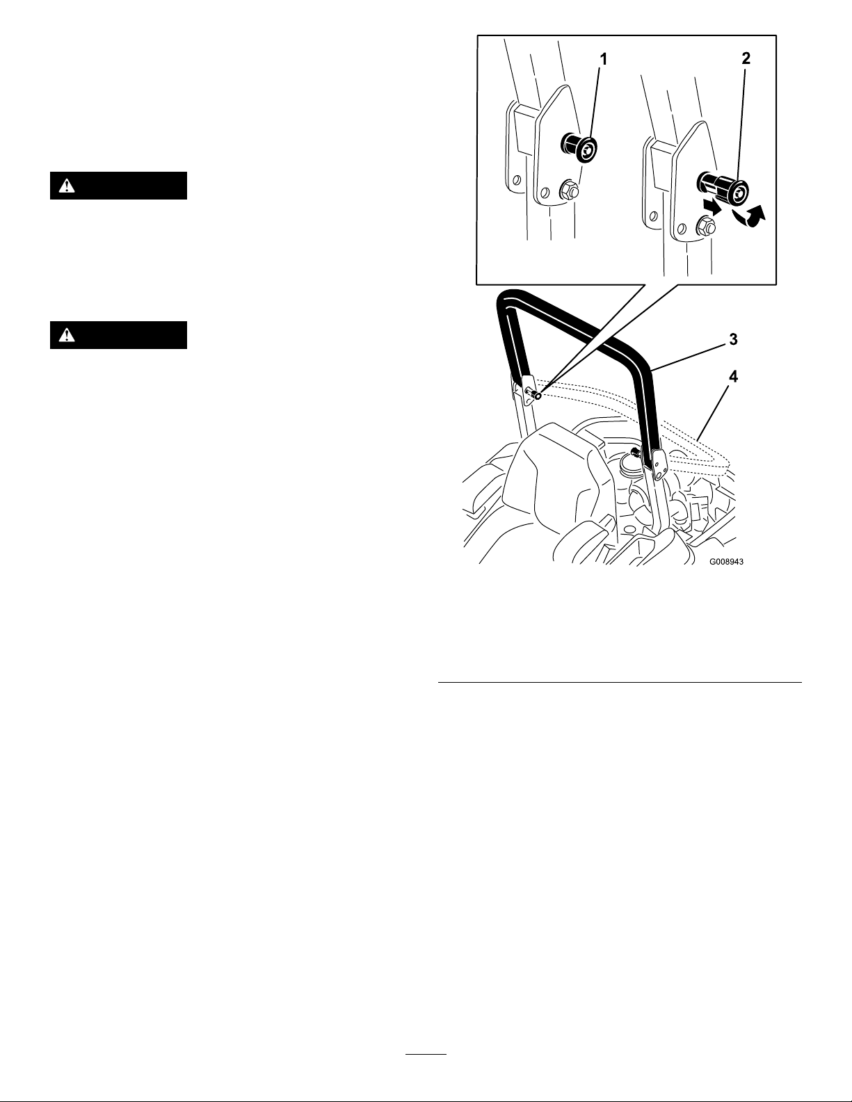
1.Tolowertherollbar,applyforwardpressureto
theupperpartoftherollbar.
2.Pullbothknobsoutandrotatethem90°sothey
arenotengaged(Figure8).
3.Lowertherollbartothedownposition(Figure
8).
Figure8
1.ROPSknob
2.PullROPSknoboutand
rotate90degrees
4.Toraisetherollbar,raisetherollbartothe
operateposition,rotatetheknobssothatthey
movepartiallyintothegrooves(Figure8).
5.Raisetherollbartothefulluprightpositionwhile
pushingontheupperrollbarandthepinswill
snapintopositionwhentheholesalignwiththe
pins(Figure8).
3.Rollbarintheupright
position
4.Rollbarinthefolded
position
Important:Alwaysusetheseatbeltwiththe
rollbarintheraisedposition.
g008943
6.Pushontherollbarandensurethatbothpins
areengaged.
20
Page 21
EnteringtheUserPosition
Usethemowerdeckasasteptogetintotheuser
position(Figure9).
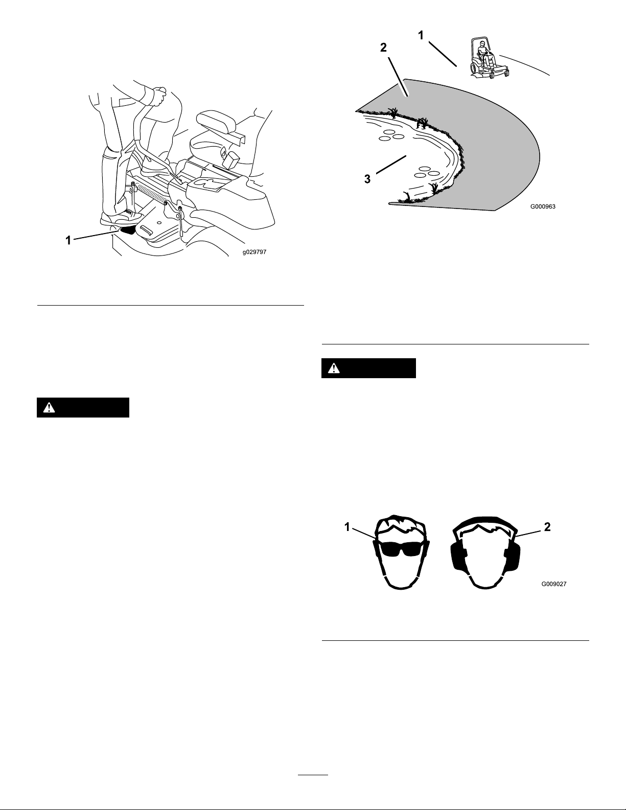
g000963
Figure10
Figure9
1.Mowerdeck
ThinkSafetyFirst
Pleasereadallsafetyinstructionsandsymbolsinthe
safetysection.Knowingthisinformationcouldhelp
youorbystandersavoidinjury.
DANGER
Operatingonwetgrassorsteepslopescan
causeslidingandlossofcontrol.
Wheelsdroppingoveredgescancause
rollovers,whichmayresultinseriousinjury,
deathordrowning.
Thereisnorolloverprotectionwhentheroll
barisdown.
1.SafeZone—usethe
g029797
ZMasterhereonslopes
lessthan15degreesor
atareas.
2.DangerZone—usea
walk-behindmowerand/or
ahandtrimmeronslopes
greaterthan15degrees,
neardrop-offsandwater.
3.Water
CAUTION
Thismachineproducessoundlevelsin
excessof85dBAattheoperatorsearandcan
causehearinglossthroughextendedperiods
ofexposure.
Wearhearingprotectionwhenoperatingthis
machine.
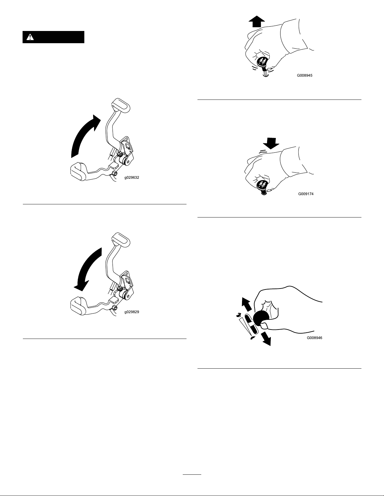
Theuseofprotectiveequipmentforeyes,ears,feet,
andheadisrecommended.
Alwayskeeptherollbarintheraisedand
lockedpositionandusetheseatbelt.
Readandfollowtherolloverprotection
instructionsandwarnings.
Toavoidlossofcontrolandpossibilityof
rollover:
•Donotoperateneardrop-offsornear
water.
•Donotoperateonslopesgreaterthan
15degrees.
•Reducespeedanduseextremecautionon
slopes.
•Avoidsuddenturnsorrapidspeed
changes.
Figure11
1.Wearsafetyglasses
2.Wearhearingprotection
OperatingtheParking Brake
Alwayssettheparkingbrakewhenyoustopthe
machineorleaveitunattended.
21
g009027
Page 22
SettingtheParkingBrake
WARNING
Parkingbrakemaynotholdmachineparked
onaslopeandcouldcausepersonalinjury
orpropertydamage.
Donotparkonslopesunlesswheelsare
chockedorblocked
Figure12
ReleasingtheParkingBrake
g008945
Figure14
DisengagingtheBlade-Control Switch(PTO)
g029632
g009174
Figure15
OperatingtheThrottle
ThethrottlecontrolcanbemovedbetweenFastand
Slowpositions(Figure16).
Figure13
OperatingtheMower Blade-ControlSwitch(PTO)
Theblade-controlswitch(PTO)startsandstopsthe
mowerbladesandanypoweredattachments.
EngagingtheBlade-Control Switch(PTO)
Note:Engagingtheblade-controlswitch(PTO)with
thethrottlepositionathalforlesswillcauseexcessive
weartothedrivebelts.
AlwaysusetheFastpositionwhenturningonthe
mowerdeckwiththeblade-controlswitch(PTO).
g029829
g008946
Figure16
OperatingtheChoke
Usethechoketostartacoldengine.
1.Iftheengineiscold,usethechoketostartthe
engine.
2.Pulluponthechokeknobtoengagethechoke
beforeusingtheignitionswitch(Figure17).
3.Pushdownonthechoketodisengagethechoke
aftertheenginehasstarted(Figure17).
22
Page 23
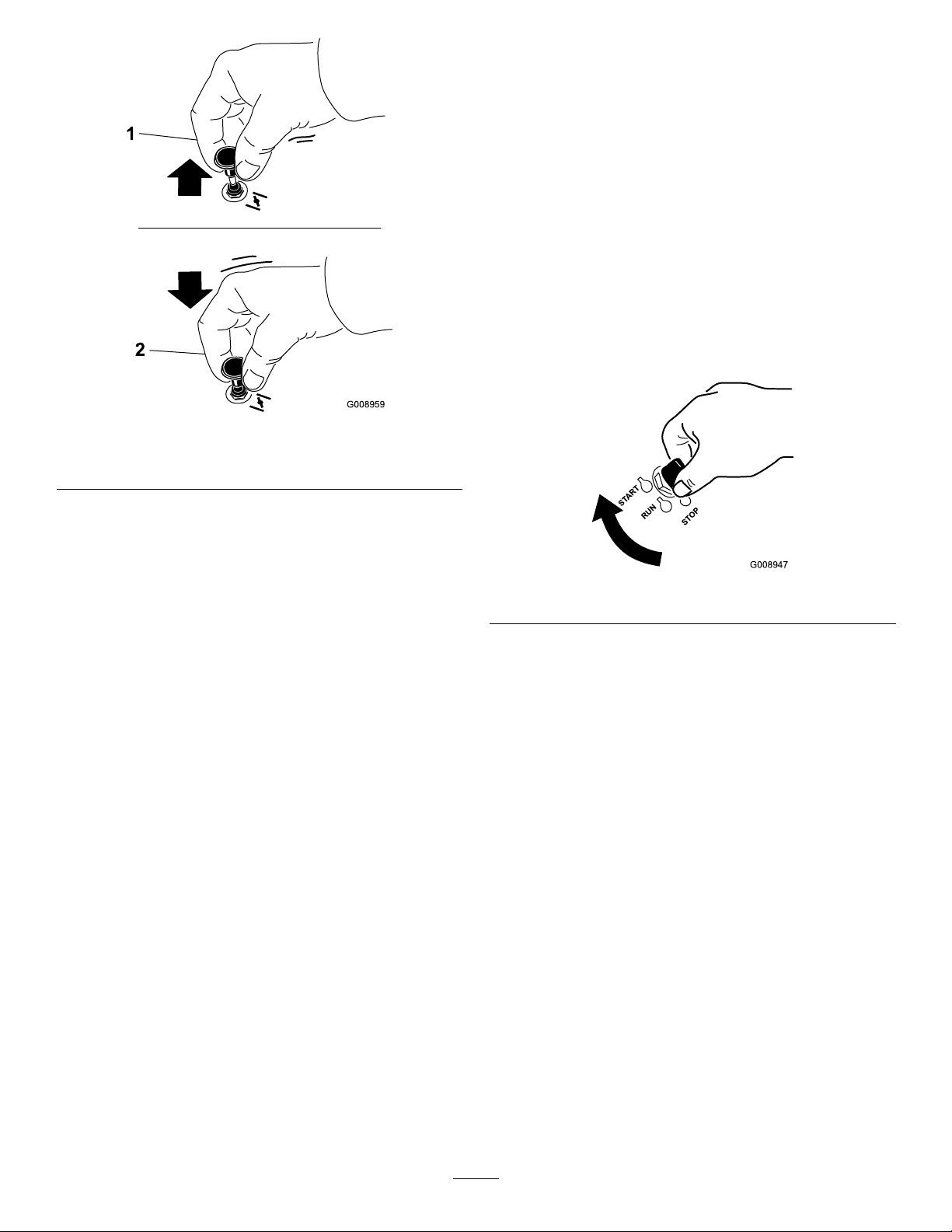
Figure17
1.Onposition2.Offposition
OperatingtheIgnition Switch
1.TurntheignitionkeytotheStartposition(Figure
18).
Note:Whentheenginesstarts,releasethekey.
Important:Donotengagestarterformore
than5secondsatatime.Iftheenginefails
tostartallowa15secondcool-downperiod
betweenattempts.Failuretofollowthese
instructionscanburnoutthestartermotor.
Note:Additionalstartingcyclesmaybe
requiredwhenstartingtheenginefortherst
timeafterthefuelsystemhasbeenwithoutfuel
completely.
g008959
Figure18
2.Turntheignitionkeytostoptostoptheengine.
UsingtheFuelShutoff Valve
Thefuelshutoffvalveislocatedundertheseat.Move
theseatforwardtoaccessit.
Closethefuelshutoffvalvefortransport,maintenance,
andstorage.
Ensurethefuelshutoffvalveisopenwhenstarting
theengine.
g008947
23
Page 24

Figure19
1.Onposition2.Offposition
StartingandStoppingthe Engine
g008948
StartingtheEngine
1.RaisetheROPSupandlockintoplace,siton
theseat,andfastentheseatbelt.
2.Movethemotioncontrolstoneutral-locked
position.
3.Settheparkingbrake;refertoSettingthe
ParkingBrake(page22).
4.Movetheblade-controlswitch(PTO)totheOff
position(Figure20).
5.Movethethrottlelevermidwaybetweenthe
SlowandFastpositions.
g029634
Figure20
6.TurntheignitionkeytotheStartposition(Figure
21).
Note:Whentheenginesstarts,releasethekey.
Important:Donotengagestarterformore
than5secondsatatime.Iftheenginefails
tostartallowa15-secondcool-downperiod
betweenattempts.Failuretofollowthese
instructionscanburnoutthestartermotor.
Note:Additionalstartingcyclesmaybe
requiredwhenstartingtheenginefortherst
timeafterthefuelsystemhasbeenwithoutfuel
completely.
g008947
Figure21
24
Page 25

StoppingtheEngine
UsingtheSafety-Interlock
CAUTION
Childrenorbystandersmaybeinjuredifthey
moveorattempttooperatethemachinewhile
itisunattended.
Alwaysremovetheignitionkeyandsetthe
parkingbrakewhenleavingthemachine
unattended,evenifjustforafewminutes.
Lettheengineidleatslowthrottle(turtle)for60
secondsbeforeturningtheignitionswitchoff.
System
CAUTION
Ifsafety-interlockswitchesaredisconnected
ordamagedthemachinecouldoperate
unexpectedlycausingpersonalinjury.
•Donottamperwiththeinterlockswitches.
•Checktheoperationoftheinterlock
switchesdailyandreplaceanydamaged
switchesbeforeoperatingthemachine.
Understandingthe Safety-InterlockSystem
Thesafety-interlocksystemisdesignedtopreventthe
enginefromstartingunless:
•Theparkingbrakeisengaged.
•Theblade-controlswitch(PTO)isdisengaged.
•Themotion-controlleversareintheneutral-locked
position.
Figure22
Important:Makesurethatthefuelshutoffvalveis
closedbeforetransportingorstoringthemachine,
asfuelleakagemayoccur.Settheparkingbrake
beforetransporting.Makesuretoremovethekey
asthefuelpumpmayrunandcausethebattery
tolosecharge.
Thesafety-interlocksystemalsoisdesignedtostop
theenginewhenthetractioncontrolsaremovedfrom
thelockedpositionwiththeparkingbrakeengagedor
ifyourisefromtheseatwhenthePTOisengaged.
Thehourmeterhassymbolstonotifytheuserwhen
theinterlockcomponentisinthecorrectposition.
Whenthecomponentisinthecorrectposition,a
trianglewilllightupinthecorrespondingsquare.
g029635
g009181
Figure23
1.Triangleslightupwhentheinterlockcomponentsareinthe
correctposition
TestingtheSafety-Interlock System
ServiceInterval:Beforeeachuseordaily
25
Page 26

Testthesafety-interlocksystembeforeyouusethe
machineeachtime.Ifthesafetysystemdoesnot
operateasdescribedbelow,haveanAuthorized
ServiceDealerrepairthesafetysystemimmediately .
1.Sittingontheseat,engagetheparkingbrake
andmovetheblade-controlswitch(PTO)tothe
Onposition.Trystartingtheengine;theengine
shouldnotcrank.
2.Sittingontheseat,engagetheparkingbrake
andmovetheblade-controlswitch(PTO)tothe
Offposition.Moveeithermotion-controllever
(outofneutral-lockedposition).Trystartingthe
engine;theengineshouldnotcrank.Repeatfor
othercontrollever.
3.Sittingontheseat,engagetheparkingbrake,
movetheblade-controlswitch(PTO)totheOff
position,andmovethemotion-controllevers
toneutral-lockposition.Nowstarttheengine.
Whiletheengineisrunning,releasetheparking
brake,engagetheblade-controlswitch(PTO)
andriseslightlyfromtheseat;theengineshould
stop.
4.Sittingontheseat,engagetheparkingbrake,
movetheblade-controlswitch(PTO)totheOff
position,andmovethemotion-controllevers
toneutral-lockposition.Nowstarttheengine.
Whiletheengineisrunning,centereithermotion
controlandmove(forwardorreverse);the
engineshouldstop.Repeatforothermotion
control.
5.Sittingontheseat,disengagetheparkingbrake,
movetheblade-controlswitch(PTO)totheOff
position,andmovethemotion-controlleversto
neutral-lockposition.Trystartingtheengine;the
engineshouldnotcrank.
UsingtheMotion-ControlLevers
Figure24
1.Motion-control
lever—neutral-lock
position
2.Center,unlockedposition5.Frontofmachine
3.Forward
DrivingForward
c:\data\documentum\checkout\g004532
4.Backward
DrivingForwardor Backward
Thethrottlecontrolregulatestheenginespeedas
measuredinrpm(revolutionsperminute).Place
thethrottlecontrolintheFastpositionforbest
performance.Alwaysoperateinthefullthrottle
positionwhenmowing.
CAUTION
Machinecanspinveryrapidly.Operatormay
losecontrolofmachineandcausepersonal
injuryordamagetomachine.
•Usecautionwhenmakingturns.
•Slowthemachinedownbeforemaking
sharpturns.
Note:Theenginewillkillifthetraction-controllevers
aremovedwiththeparkingbrakeengaged.
Tostop,pullthemotion-controlleverstotheneutral
position.
1.Releasetheparkingbrake;refertoReleasing
theParkingBrake(page22).
2.Movetheleverstothecenter,unlockedposition.
3.Togoforward,slowlypushthemotion-control
leversforward(Figure25).
26
Page 27

StoppingtheMachine
Tostopthemachine,movethetraction-controllevers
toneutral,andthenmovethemtothelockedposition,
disengagethepowertakeoff(blade-controlswitch
(PTO),andturntheignitionkeytotheOffposition.
Settheparkingbrakewhenyouleavethemachine;
refertoSettingtheParkingBrake(page22).
Remembertoremovethekeyfromtheignitionswitch.
CAUTION
Childrenorbystandersmaybeinjuredifthey
moveorattempttooperatethemachinewhile
itisunattended.
Alwaysremovetheignitionkeyandsetthe
parkingbrakewhenleavingthemachine
unattended,evenifjustforafewminutes.
Figure25
DrivingBackward
1.Movetheleverstothecenter,unlockedposition.
2.Togobackward,slowlypullthemotion-control
leversrearward(Figure26).
g008952
AdjustingtheHeight-of-Cut
UsingtheTransportLock
Thetransportlockhas2positions,andisusedwiththe
deck-liftpedal.Thereisalockpositionandaunlock
positionforthetransportposition.Thetransportlock
isusedwiththedeck-liftpedal(Figure27).
Figure26
g008953
27
Page 28

AdjustingtheHeight-of-CutPin
Theheight-of-cutisadjustedfrom25to140mm(1
to5-1/2inches)in6mm(1/4inch)incrementsby
relocatingtheclevispinintodifferentholelocations.
1.Movethetransportlocktothelockposition.
2.Pushonthedeck-liftpedalwithyourfoot,and
raisethemowerdecktothetransportposition
(alsothe140mm(5-1/2inches)cuttingheight
position)asshowninFigure28.
3.Toadjust,rotatethepin90degreesandremove
thepinfromtheheight-of-cutbracket(Figure
28).
4.Selectaholeintheheight-of-cutbracket
correspondingtotheheight-of-cutdesired,and
insertthepin(Figure28).
5.Pushonthedecklift,pullbackonthetransport
lock,andslowlylowerthemowerdeck.
Figure27
Transport-LockPositions
1.Transportlock3.Unlockposition—doesnot
lockthemowerdeckinto
transportposition
2.Lockposition—mower
deckwilllockintotransport
position
g008955
28
Page 29

Figure30
g029956
Figure28
1.Deck-liftpedal
2.Cut-of-heightpin
3.Transportlock
AdjustingtheAnti-Scalp Rollers
Wheneveryouchangetheheight-of-cut,itis
recommendedtoadjusttheheightoftheanti-scalp
rollers.
1.Disengagetheblade-controlswitch(PTO),move
themotion-controlleverstotheneutral-locked
position,andsettheparkingbrake.
2.Stoptheengine,removethekey,andwait
forallmovingpartstostopbeforeleavingthe
operatingposition.
3.Adjusttheanti-scalprollersasshowninFigure
29,Figure30,andFigure31.
g029636
1.Anti-scalproller3.Flangenut
2.Bushing4.Bolt
Figure31
1.Anti-scalproller4.Flangenut
2.Spacer
3.Bushing
5.Bolt
g029957
Figure29
1.Anti-scalproller4.Flangenut
2.Spacer
3.Bushing
5.Bolt
AdjustingtheFlowBafe
CamLocks
Thisprocedureisapplicableonlytomachineswith
theow-bafelocks.Certainmodelswillhavenuts
andboltsinplaceoftheow-bafelocksandcanbe
adjustedthesame.
Themower-dischargeowcanbeadjustedfor
differenttypesofmowingconditions.Positionthecam
locksandbafetogivethebestqualityofcut.
g029955
1.Disengagetheblade-controlswitch(PTO),move
themotion-controlleverstotheneutral-locked
position,andsettheparkingbrake.
2.Stoptheengine,removethekey,andwait
forallmovingpartstostopbeforeleavingthe
operatingposition.
3.Toadjustthecamlocks,swingtheleverupto
loosenthecamlock(Figure32).
29
Page 30

4.Adjustthebafeandcamlocksintheslotsto
thedesireddischargeow.
5.Swingtheleverbackovertotightenthebafe
andcamlocks(Figure32).
6.Ifthecamlocksdonotlockthebafeintoplace
oritistootight,loosentheleverandthenrotate
thecamlock.
Note:Adjustthecamlockuntilthedesired
lockingpressureisachieved.
Figure32
PositionB
Usethispositionwhenbagging.Alwaysalignitwith
thebloweropening.
g005833
Figure34
g027727
PositionC
PositioningtheFlowBafe
Thefollowingguresareonlyrecommendationsfor
use.Adjustmentswillvarybygrasstype,moisture
content,andtheheightofthegrass.
Note:Iftheenginepowerdrawsdownandthe
mowergroundspeedisthesame,openupthebafe.
PositionA
Thisisthefullrearposition.Thesuggestedusefor
thispositionisasfollows:
•Short,lightgrassmowingconditions
•Dryconditions
•Smallergrassclippings
•Propelsgrassclippingsfartherawayfromthe
mower
Thisisthefullopenposition.Thesuggestedusefor
thispositionisasfollows:
•Tall,densegrassmowingconditions
•Wetconditions
•Lowerstheengine-powerconsumption
•Allowsincreasedgroundspeedinheavyconditions
•ThispositionissimilartothebenetsoftheT oro
SFSmower
Figure33
g005834
Figure35
g005832
30
Page 31

PositioningtheSeat
Theseatmovesforwardandbackward.Positionthe
seatwhereyouhavethebestcontrolofthemachine
andaremostcomfortable.
Toadjust,movetheleversidewaystounlocktheseat
(Figure36).
Figure36
UnlatchingtheSeat
Positionthesuspensionsystemwhereyouaremost
comfortable.
AdjustingtheRear,Shock Assemblies
Theslotsfortherear,shockassemblieshavedetent
positionsforreference.Therear,shockassemblies
canbepositionedanywhereintheslot,notjustthe
detentpositions.
Thefollowinggraphicshowsthepositionforasoftor
rmrideandthedifferentdetentpositions(Figure38).
g029830
AdjustingtheMyRide™
g030065
Figure38
1.Firmestposition3.Detentsintheslots
2.Softestposition
Note:Ensuretheleftandrightrear,shockassemblies
arealwaysadjustedtothesamepositions.
g030021
Figure37
SuspensionSystem
TheMyRide™suspensionsystemadjuststoprovide
asmoothandcomfortableride.Adjustingtherear
2shockassembliesistheeasiestandquickest
adjustmentforchangingthesuspensionsystem.
31
Page 32

Adjusttherear,shockassemblies(Figure39).
Toadjustthefront,shockassembly ,opentheoor
panandadjustitbyusingaspannerwrench(Toro
partno.132–5069)oraslip-jointpliers(Figure40).
g030024
g030569
Figure40
1.Middleposition
2.Firmride
3.Softride
Usingthe Drive-Wheel-Release Valves
WARNING
Handsmaybecomeentangledintherotating
drivecomponentsbelowtheenginedeck,
whichcouldresultinseriousinjury.
Stoptheengine,removethekey,andallow
allmovingpartstostopbeforeaccessingthe
drive-wheel-releasevalves.
WARNING
Theengineandhydraulic-driveunitscan
becomeveryhot.Touchingahotengineor
hydraulic-driveunitscancausesevereburns.
Figure39
AdjustingtheFront,Shock Assembly
Thefront,shockassemblyissetatthemiddleposition
andisnormallynotadjusted.
Allowtheengineandhydraulic-driveunits
g030019
tocoolcompletelybeforeaccessingthe
drive-wheel-releasevalves.
Thedrive-wheel-releasevalvesarelocatedinthe
backofeachhydraulic-driveunit,undertheseat.
Note:Makesurethereleasevalvesareinthefully
horizontalpositionwhenoperatingthemachineor
severedamagetothehydraulicsystemcanoccur.
1.DisengagethePTO(blade-controlswitch)and
turntheignitionkeytotheOffposition,move
32
Page 33

theleverstoneutral-lockedposition,applythe
parkingbrake,andremovethekey.
2.Rotatetherelease-valveleversverticallytopush
themachine(Figure41).
Note:Thisallowshydraulicoiltobypassthe
pumpenablingthewheelstoturn.
3.Disengagetheparkingbrakebeforepushing
themachine.
DANGER
Withoutagrassdeector,dischargecover,or
acompletegrass-catcherassemblymounted
inplace,youandothersareexposedtoblade
contactandthrowndebris.Contactwith
rotatingmowerblade(s)andthrowndebris
willcauseinjuryordeath.
•Neverremovethegrassdeectorfrom
themowerbecausethegrassdeector
routesmaterialdowntowardtheturf.Ifthe
grassdeectoriseverdamaged,replaceit
immediately.
•Neverputyourhandsorfeetunderthe
mower.
•Nevertrytoclearthedischargeareaor
mowerbladesunlessyoumovethepower
takeoff(blade-controlswitch(PTO)tothe
Offposition,rotatetheignitionkeytothe
Offposition,andremovethekey.
Figure41
1.Verticaltopushthe
machine
4.Rotatetherelease-valvelevershorizontallyto
runthemachine(Figure41).
2.Horizontaltorunthe
machine
UsingtheSideDischarge
Themowerhasahingedgrassdeectorthat
dispersesclippingstothesideanddowntowardthe
turf.
g029831
•Makesurethegrassdeectorisinthe
downposition.
33
Page 34

TransportingtheMachine
LoadingtheMachine
Useaheavy-dutytrailerortrucktotransportthe
machine.Ensurethatthetrailerortruckhasall
thenecessarybrakes,lighting,andmarkingas
requiredbylaw.Pleasecarefullyreadallthesafety
instructions.Knowingthisinformationcouldhelpyou,
yourfamily,petsorbystandersavoidinjury .
WARNING
Drivingonthestreetorroadwaywithoutturn
signals,lights,reectivemarkings,oraslow
movingvehicleemblemisdangerousandcan
leadtoaccidentscausingpersonalinjury.
Donotdrivemachineonapublicstreetor
roadway.
Totransportthemachine:
1.Ifusingatrailer,connectittothetowingvehicle,
andconnectthesafetychains.
2.Ifapplicable,connectthetrailerbrakes.
3.Loadthemachineontothetrailerortruck.
4.Stoptheengine,removethekey,setthebrake,
andclosethefuelvalve.
5.Usethemetaltie-downloopsonthemachineto
securelyfastenthemachinetothetrailerortruck
withstraps,chains,cable,orropes(Figure42).
Useextremecautionwhenloadingorunloading
machinesontoatraileroratruck.Useafull-width
rampthatiswiderthanthemachineforthisprocedure.
Backuprampsanddriveforwarddownramps(Figure
43).
Figure43
1.Backupramps
2.Driveforwarddownramps
Important:Donotusenarrowindividualramps
foreachsideofthemachine.
Ensuretherampislongenoughsothattheanglewith
thegrounddoesnotexceed15degrees(Figure44).
Onatground,thisrequiresaramptobeatleast4
timesaslongastheheightofthetrailerortruckbed
totheground.Asteeperanglemaycausemower
componentstogetcaughtastheunitmovesfromthe
ramptothetrailerortruck.Steeperanglesmayalso
causethemachinetotiporlosecontrol.Ifloadingon
ornearaslope,positionthetrailerortrucksothatitis
onthedownsideoftheslopeandtherampextends
uptheslope.Thiswillminimizetherampangle.
g028043
1.Tractionunittie-downloops
g029641
Figure42
34
Page 35

WARNING
Loadingamachineontoatrailerortruck
increasesthepossibilityoftip-overandcould
causeseriousinjuryordeath.
•Useextremecautionwhenoperatinga
machineonaramp.
•EnsurethattheROPSisintheupposition
andusetheseatbeltwhenloadingor
unloadingthemachine.Ensurethatthe
ROPSwillclearthetopofanenclosed
trailer.
•Useonlyafull-widthramp;donotuse
individualrampsforeachsideofthe
machine.
•Donotexceeda15-degreeanglebetween
therampandthegroundorbetweenthe
rampandthetrailerortruck.
•Ensurethelengthoframpisatleast4
timesaslongastheheightofthetrailer
ortruckbedtotheground.Thiswill
ensurethatrampangledoesnotexceed15
degreesonatground.
•Backuprampsanddriveforwarddown
ramps.
•Avoidsuddenaccelerationordeceleration
whiledrivingthemachineonarampas
thiscouldcausealossofcontrolora
tip-oversituation.
1.Full-widthrampinstowed
position
2.Sideviewoffull-width
rampinloadingposition
3.Notgreaterthan
15degrees
g027996
Figure44
4.Rampisatleast4times
aslongastheheightof
thetrailerortruckbedto
theground
5.H=heightofthetraileror
truckbedtotheground
6.Trailer
35
Page 36

OperatingTips
UsingtheFastThrottleSetting
Forbestmowingandmaximumaircirculation,operate
theengineattheFastthrottleposition.Airisrequired
tothoroughlycutgrassclippings,sodonotsetthe
height-of-cutsolowastototallysurroundthemower
byuncutgrass.Alwaystrytohaveonesideofthe
mowerfreefromuncutgrass,whichallowsairtobe
drawnintothemower.
CuttingaLawnfortheFirstTime
CuttingLongGrass
Ifthegrassiseverallowedtogrowslightlylongerthan
normal,orifitcontainsahighdegreeofmoisture,
raisethecuttingheighthigherthanusualandcutthe
grassatthissetting.Thencutthegrassagainusing
thelower,normalsetting.
StoppingtheMachine
Ifyoumuststoptheforwardmotionofthemachine
whilemowing,aclumpofgrassclippingsmaydrop
ontoyourlawn.T oavoidthis,moveontoapreviously
cutareawiththebladesengaged.
Cutgrassslightlylongerthannormaltoensurethat
thecuttingheightofthemowerdoesnotscalpany
unevenground.However,thecuttingheightusedin
thepastisgenerallythebestonetouse.Whencutting
grasslongerthansixinchestall,youmaywanttocut
thelawntwicetoensureanacceptablequalityofcut.
Cutting1/3oftheGrassBlade
Itisbesttocutonlyabout1/3ofthegrassblade.
Cuttingmorethanthatisnotrecommendedunless
grassissparse,oritislatefallwhengrassgrows
moreslowly .
AlternatingtheMowingDirection
Alternatemowingdirectiontokeepthegrassstanding
straight.Thisalsohelpsdisperseclippingswhich
enhancesdecompositionandfertilization.
MowingatCorrectIntervals
Normally,moweveryfourdays.Butremember,
grassgrowsatdifferentratesatdifferenttimes.So
tomaintainthesamecuttingheight,whichisagood
practice,mowmoreofteninearlyspring.Asthe
grassgrowthrateslowsinmidsummer,mowless
frequently.Ifyoucannotmowforanextendedperiod,
rstmowatahighcuttingheight;thenmowagaintwo
dayslateratalowerheightsetting.
KeepingtheUndersideofthe
MowerClean
Cleanclippingsanddirtfromtheundersideofthe
moweraftereachuse.Ifgrassanddirtbuildupinside
themower,cuttingqualitywilleventuallybecome
unsatisfactory.
MaintainingtheBlade
Maintainasharpbladethroughoutthecuttingseason
becauseasharpbladecutscleanlywithouttearingor
shreddingthegrassblades.Tearingandshredding
turnsgrassbrownattheedges,whichslowsgrowth
andincreasesthechanceofdisease.Checkthe
cutterbladesdailyforsharpness,andforanywearor
damage.Filedownanynicksandsharpentheblades
asnecessary.Ifabladeisdamagedorworn,replace
itimmediatelywithagenuineT ororeplacementblade.
AdjustingtheCuttingSpeed
Toimprovecutquality,useaslowergroundspeed
incertainconditions.
AvoidingCuttingTooLow
Ifthecuttingwidthofthemoweriswiderthanthe
moweryoupreviouslyused,raisethecuttingheightto
ensurethatuneventurfisnotcuttooshort.
36
Page 37

Maintenance
RecommendedMaintenanceSchedule(s)
MaintenanceService
Interval
Aftertherst8hours
Aftertherst100hours
Aftertherst250hours
Beforeeachuseordaily
Every50hours
Every100hours
MaintenanceProcedure
•Changetheengineoil.
•Checkthewheellug-nuttorque.
•Checkthewheelhubslotted-nuttorque.
•Checktheparkingbrakeadjustment.
•Changethehydraulicltersandhydraulicoilwhenusinganytypeofoil.
•Checkthesafetysystem.
•Checktheengine-oillevel.
•Checktheseatbelt.
•Checktherolloverprotectionsystem(ROPS)knobs.
•Cleantheenginescreenandtheoilcooler.
•Checkandcleanthehydraulic-unitshrouds.
•Inspecttheblades.
•Cleanthemowerdeck.
•Greasethemower-deckspindlesandtheidlerarm.
•Checkthesparkarrester(ifequipped).
•Checkthetirepressure.
•Inspectthebeltsforcracksandwear.
•Checkthehydraulicoillevel.
•Lubricatethemower-deck-liftpivots.
•Changetheengineoil(moreoftenindirtyordustyconditions).
•Check,cleanandregapthesparkplug.
•Checkandcleanengine-coolingnsandshrouds.
Every200hours
Every250hours
Every500hours
Monthly
Yearly
Yearlyorbeforestorage
•Changetheengine-oillter.
•Replacetheprimaryairlter.
•Checkthesecondaryairlter.
•ChangethehydraulicltersandhydraulicoilwhenusingMobil®1oil(moreoftenin
dirtyordustyconditions).
•Replacethesecondaryairlter.
•Replacethefuellter(moreoftenindirtyordustyconditions).
•Checkthewheellug-nuttorque.
•Checkthewheelhubslotted-nuttorque.
•Adjustthecaster-pivotbearing.
•Checktheparkingbrakeadjustment.
•ChangethehydraulicltersandhydraulicoilwhenusingToro®HYPR-OIL™500
hydraulicoil(moreoftenindirtyordustyconditions).
•Checkthebatterycharge.
•Greasethepump-belt-idlerarm.
•Greasethefrontcasterpivots(moreoftenindirtyordustyconditions).
•Repackthefrontcaster-wheelbearings(moreoftenindirtyordustyconditions).
•Lubricatethecaster-wheelhubs.
•Paintchippedsurfaces.
•Checkallmaintenanceprocedureslistedabovebeforestorage.
Important:Refertoyourengineoperator'smanualforadditionalmaintenanceprocedures.
37
Page 38

CAUTION
Ifyouleavethekeyintheignitionswitch,someonecouldaccidentlystarttheengineand
seriouslyinjureyouorotherbystanders.
Removethekeyfromtheignitionbeforeyoudoanymaintenance.
Lubrication
Greasemorefrequentlywhenoperatingconditions
areextremelydustyorsandy.
GreaseType:No.2general-purposelithium-based
ormolybdenum-basedgrease
1.Disengagetheblade-controlswitch(PTO),move
themotion-controlleverstotheneutral-locked
position,andsettheparkingbrake.
2.Stoptheengine,removethekey,andwait
forallmovingpartstostopbeforeleavingthe
operatingposition.
3.Cleanthegreasettingswitharag.
Note:Makesuretoscrapeanypaintoffthe
frontofthetting(s).
4.Connectagreaseguntothetting.
5.Pumpgreaseintothettingsuntilgreasebegins
tooozeoutofthebearings.
6.Wipeupanyexcessgrease.
AddingLightOilorSpray Lubrication
GreasingtheMower
ServiceInterval:Every50hours—Greasethe
mower-deckspindlesandtheidler
arm.
Yearly—Greasethepump-belt-idlerarm.
Yearly—Greasethefrontcasterpivots(more
oftenindirtyordustyconditions).
Yearly—Repackthefrontcaster-wheelbearings
(moreoftenindirtyordustyconditions).
Important:Makesurecuttingunitspindlesare
fullofgreaseweekly.
1.Disengagetheblade-controlswitch(PTO),move
themotion-controlleverstotheneutral-locked
position,andsettheparkingbrake.
2.Stoptheengine,removethekey,andwait
forallmovingpartstostopbeforeleavingthe
operatingposition.
3.Greasethemowerdeckidler-pulleypivotuntil
greasecomeoutthebottom(Figure46).
4.Greasethe3spindlebearingsuntilgrease
comesout(Figure46).
ServiceInterval:Every100hours
Lubricatethedeck-liftpivots.
g009029
Figure46
5.Greasethedrive-belt-idlerarm(Figure47).
g029642
Figure45
38
Page 39

Figure47
6.Removethedustcapandadjustthecaster
pivots.
Note:Keepthedustcapoffuntilgreasingis
done;refertoAdjustingtheCaster-PivotBearing
(page51).
7.Removethehexplug.
8.Threadagreasettingintothehole.
9.Pumpgreaseintothettinguntilitoozesout
aroundthetopbearing.
10.Removethegreasettinginthehole.
11.Installthehexpluganddustcap(Figure48).
Lubricatingthe Caster-WheelHubs
ServiceInterval:Y early
1.Stoptheengine,waitforallmovingpartstostop,
removethekey,andengagetheparkingbrake.
g009030
g006115
Figure49
1.Sealguard2.Spacernutwithwrench
ats
2.Raisethemowerforaccess.
3.Removethecasterwheelfromthecasterforks.
4.Removethesealguardsfromthewheelhub.
5.Removeoneofthespacernutsfromtheaxle
assemblyinthecasterwheel.
Note:Thread-lockingadhesivehasbeen
appliedtolockthespacernutstotheaxle.
6.Removetheaxle(withtheotherspacernutstill
assembledtoit)fromthewheelassembly.
Figure48
12.Greasethecaster-wheelbearings(Figure48).
7.Pryoutsealsandinspectbearingsforwearor
damageandreplaceifnecessary.
8.Packthebearingswithageneral-purpose
grease.
9.Insert1bearingand1newsealintothewheel.
Note:Thesealsmustbereplaced.
g029643
10.Iftheaxleassemblyhashadbothspacer
nutsremoved(orbrokenloose),applya
thread-lockingadhesiveto1spacernut,and
threaditontotheaxlewiththewrenchats
facingoutward.
Note:Donotthreadthespacernutallof
thewayontotheendoftheaxle.Leave
approximately3mm(1/8inch)fromtheouter
surfaceofthespacernuttotheendoftheaxle
insidethenut.
11.Inserttheassemblednutandaxleintothewheel
onthesideofthewheelwiththenewsealand
bearing.
39
Page 40

12.Withtheopenendofthewheelfacingup,ll
theareainsidethewheelaroundtheaxlefullof
general-purposegrease.
13.Insertthesecondbearingandnewsealintothe
wheel.
14.Applyathread-lockingadhesivetothesecond
spacernut,andthreaditontotheaxlewiththe
wrenchatsfacingoutward.
15.Torquethenutto8to9N-m(75to80in-lb),
loosen,thentorqueto2to3N-m(20to25in-lb).
EngineMaintenance
WARNING
Contactwithhotsurfacesmaycausepersonal
injury.
Keephands,feet,face,clothing,andother
bodypartsawaythemuferandotherhot
surfaces.
Note:Makesureaxledoesnotextendbeyond
eithernut.
16.Installthesealguardsoverthewheelhub,and
insertwheelintothecasterfork.
17.Installthecasterboltandtightenthenutfully.
Important:Topreventsealandbearingdamage,
checkthebearingadjustmentoften.Spinthe
castertire.Thetireshouldnotspinfreely(more
than1or2revolutions)orhaveanysideplay.If
thewheelspinsfreely,adjustthetorqueonthe
spacernutuntilthereisaslightamountofdrag.
Applyanotherlayerofthread-lockingadhesive.
ServicingtheAirCleaner
ServiceInterval:Every250hours—Replacethe
primaryairlter.
Every250hours—Checkthesecondaryair
lter.
Every500hours—Replacethesecondaryair
lter.
Note:Servicetheaircleanermorefrequentlyif
operatingconditionsareextremelydustyorsandy .
RemovingtheFilters
1.DisengagethePTO,movethemotion-control
leverstotheneutral-lockedposition,andsetthe
parkingbrake.
2.Stoptheengine,removethekey,andwait
forallmovingpartstostopbeforeleavingthe
operatingposition.
3.Pushdowntoreleasetheretainingclampson
theaircleaner,andpulltheair-cleanercoveroff
theair-cleanerbody(Figure50).
4.Cleantheinsideoftheair-cleanercoverwith
compressedair.
5.Gentlyslidetheprimarylteroutofthe
air-cleanerbody(Figure50).Avoidknockingthe
lterintothesideofthebody .
6.Removethesecondarylteronlyifyouintend
toreplaceit.
Important:Neverattempttocleanthe
secondarylter.Ifthesecondarylteris
dirty,thentheprimarylterisdamagedand
youshouldreplacebothlters.
7.Inspecttheprimarylterfordamagebylooking
intothelterwhileshiningabrightlightonthe
outsideofthelter.
Note:Holesinthelterwillappearasbright
spots.
Note:Ifthelterisdamageddiscardit.
40
Page 41

Figure50
ServicingtheEngineOil
OilType:Detergentoil(APIserviceSG,SH,SJ,or
higher)
OilCapacityfor74923,74925,and74927engines:
withalterchange,2.3L(77oz);withnolterchange,
2.1L(70oz)
OilCapacityfor74922,78922,and78924engines:
withalterchange,2.1L(71oz);withnolterchange,
1.8L(61oz)
Viscosity:Seethetablebelow.
g009031
1.Air-cleanerclamps
2.Air-cleanercover
3.Primaryairlter
4.Secondaryairlter
ServicingthePrimaryFilter
1.Donotcleanthepaperlter,replaceit(Figure
50).
2.Inspecttheelementfortears,anoilylm,or
damagetotherubberseal.
3.Replacethepaperelementifitisdamaged.
ServicingtheSecondaryFilter
Donotcleanthesecondarylter,replaceit.
Important:Donotattempttocleanthesecondary
lter.Ifthesecondarylterisdirty,thenthe
primarylterisdamagedandyoushouldreplace
bothlters.
InstallingtheFilters
Important:Topreventenginedamage,always
operatetheenginewithbothairltersandthe
coverinstalled.
1.Ifinstallingnewlters,checkeachlterfor
shippingdamage.
Note:Donotuseadamagedlter.
2.Ifthesecondarylterisbeingreplaced,carefully
slideitintothelterbody(Figure50).
3.Carefullyslidetheprimarylteroverthe
secondarylter(Figure50).
4.Ensurethatitisfullyseatedbypushingonthe
outerrimofthelterwhileinstallingit.
Important:Donotpressonthesoftinside
areaofthelter.
5.Installtheair-cleanercoverwiththebreathercap
down,androtatesothattheretainingclamps
lockthecoverinplace(Figure50).
g004216
Figure51
Note:Useofmulti-gradeoils(5W-20,10W-30,or
10W-40)willincreaseoilconsumption.Checktheoil
levelmorefrequentlywhenusingthem.
CheckingtheEngine-OilLevel
ServiceInterval:Beforeeachuseordaily
Note:Checktheoilwhentheengineiscold.
WARNING
Contactwithhotsurfacesmaycausepersonal
injury.
Keephands,feet,face,clothing,andother
bodypartsawayfromthemuferandother
hotsurfaces.
Important:Donotoverllthecrankcasewithoil
becausedamagetotheenginemayresult.Donot
runenginewithoilbelowtheLowmarkbecause
theenginemaybedamaged.
1.DisengagethePTO,movethemotion-control
leverstotheneutral-lockedposition,andsetthe
parkingbrake.
2.Stoptheengine,removethekey,andwait
forallmovingpartstostopbeforeleavingthe
operatingposition(Figure52).
41
Page 42

ChangingtheEngineOil
ServiceInterval:Aftertherst8hours
Every100hours(moreoftenindirtyordusty
conditions).
Note:Disposeoftheusedoilatarecyclingcenter.
g029644
1.Starttheengineandletitrunfor5minutes.
Note:Thiswarmstheoilsoitdrainsbetter.
2.Parkthemachinesothattherearisslightly
lowerthanthefronttoensurethattheoildrains
completely.
3.DisengagethePTO,movethemotion-control
leverstotheneutral-lockedposition,andsetthe
parkingbrake.
4.Stoptheengine,removethekey,andwait
forallmovingpartstostopbeforeleavingthe
operatingposition(Figure53).
Figure52
g029644
g027659
g027734
Figure53
42
Page 43

5.Slowlypourapproximately80%ofthespecied
oilintothellertubeandslowlyaddthe
additionaloiltobringittotheFullmark(Figure
54).
ChangingtheEngine-OilFilter
ServiceInterval:Every200hours
Note:Changetheengine-oilltermorefrequently
whenoperatingconditionsareextremelydustyor
sandy.
1.Draintheoilfromtheengine;refertoChanging
theEngineOil(page42).
2.Changetheengine-oillter(Figure55).
g029644
Figure54
6.Starttheengineanddrivetoaatarea.
7.Checktheoillevelagain.
g027660
g027477
Figure55
Note:Ensuretheoil-ltergaskettouchesthe
engine,andthenanextra3/4turniscompleted.
3.Fillthecrankcasewiththepropertypeofnew
oil;refertoChangingtheEngineOil(page42).
43
Page 44

ServicingtheSparkPlug
ServiceInterval:Every100hours
Makesuretheairgapbetweenthecenterandside
electrodesiscorrectbeforeinstallingthesparkplug.
Useasparkplugwrenchforremovingandinstalling
thesparkplug(s)andagappingtool/feelergaugeto
checkandadjusttheairgap.Installanewspark
plug(s)ifnecessary.
g029645
Type:Champion
®
RC12YCorequivalent
AirGap:0.76mm(0.03inch)
RemovingtheSparkPlug
1.Stoptheengine,removethekey,andwait
forallmovingpartstostopbeforeleavingthe
operatingposition.
2.DisengagethePTO,movethemotion-control
leverstotheneutral-lockedposition,andsetthe
parkingbrake.
3.Removethelefthandhydraulic-unitshroudin
theorderlistedinFigure56.
Note:Thisgivesyouaccesstothefrontspark
plug.
1.Pullthistabouttothe
sideinthedirectionofthe
arrow
2.Pulltheshroudoffofthis
frametabinthedirection
ofthearrow
g009919
Figure56
3.Pulltheshroudoffofthis
frametabinthedirection
ofthearrow
4.Shroud
4.Removethesparkplug.
Figure57
5.Installthelefthandhydraulic-unitshroud(Figure
56).
g029646
g027478
44
Page 45

CheckingtheSparkPlug
InstallingtheSparkPlug
Important:Donotcleanthesparkplug(s).
Alwaysreplacethesparkplug(s)whenithas:a
blackcoating,wornelectrodes,anoilylm,or
cracks.
Ifyouseelightbrownorgrayontheinsulator,the
engineisoperatingproperly.Ablackcoatingonthe
insulatorusuallymeanstheaircleanerisdirty .
Setthegapto0.76mm(0.03inch).
Figure58
Tightenthesparkplug(s)to24.4to29.8N-m(18to
22ft-lb).
g027479
g027735
Figure59
CheckingtheSpark Arrester(ifequipped)
ServiceInterval:Every50hours
WARNING
Hotexhaustsystemcomponentsmayignite
gasolinevaporsevenaftertheengineis
stopped.Hotparticlesexhaustedduring
engineoperationmayigniteammable
materials.Firemayresultinpersonalinjury
orpropertydamage.
Donotfuelorrunengineunlessspark
arresterisinstalled.
1.Stopengine,waitforallmovingpartstostop,
removethekey,andengagetheparkingbrake.
2.Waitformufertocool.
3.Ifthereareanybreaksinthescreenorwelds
areobserved,replacethearrester.
4.Ifpluggingofthescreenisobserved,remove
thearresterandshakelooseparticlesoutofthe
arrester,andcleanscreenitwithawirebrush
(soakinsolventifnecessary).
5.Installarresteronexhaustoutlet.
45
Page 46

FuelSystem
Maintenance
originallyinstalledatthefactorytokeepthefuel
lineawayfromcomponentsthatcancausefuelline
damage.
ReplacingtheFuelFilter
ServiceInterval:Every500hours/Yearly(whichever
comesrst)(moreoftenindirtyor
dustyconditions).
Thefuellterislocatedneartheengineonthefront
orrearsideoftheengine.
1.DisengagethePTO,movethemotion-control
leverstotheneutral-lockedposition,andsetthe
parkingbrake.
2.Stoptheengine,removethekey,andwait
forallmovingpartstostopbeforeleavingthe
operatingposition.
3.Allowthemachinetocooldown.
4.Stoptheengine,removethekey,andwait
forallmovingpartstostopbeforeleavingthe
operatingposition.
5.Closethefuel-shutoffvalveundertheseat
(Figure60).
ServicingtheFuelTank
Donotattempttodrainthefueltank.Ensurethatan
AuthorizedServiceDealerdrainsthefueltankand
servicesanycomponentsofthefuelsystem.
Figure60
1.Fuellter3.Fuel-shutoffvalve
2.Hoseclamp
6.Squeezetheendsofthehoseclampstogether
andslidethemawayfromthelter(Figure60).
7.Removethelterfromthefuellines.
8.Installanewlterandmovethehoseclamps
closetothelter(Figure60).
9.Openthefuel-shutoffvalve.
Note:Itisimportanttoinstallthefuellinehoses
andsecurewithplastictiesthesameastheywere
g008963
46
Page 47

ElectricalSystem
Maintenance
ServicingtheBattery
ServiceInterval:Monthly
WARNING
CALIFORNIA
Proposition65Warning
WARNING
Incorrectbatterycableroutingcoulddamage
themachineandcablescausingsparks.
Sparkscancausethebatterygassesto
explode,resultinginpersonalinjury.
•Alwaysdisconnectthenegative(black)
batterycablebeforedisconnectingthe
positive(red)cable.
•Alwaysreconnectthepositive(red)battery
cablebeforeconnectingthenegative
(black)cable.
Batteryposts,terminals,andrelated
accessoriescontainleadandlead
compounds,chemicalsknownto
theStateofCaliforniatocause
cancerandreproductiveharm.Wash
handsafterhandling.
DANGER
Batteryelectrolytecontainssulfuricacid
whichisadeadlypoisonandcausessevere
burns.
Donotdrinkelectrolyteandavoidcontact
withskin,eyes,orclothing.Wearsafety
glassestoshieldyoureyesandrubbergloves
toprotectyourhands.
RemovingtheBattery
WARNING
1.Disengagetheblade-controlswitch(PTO),move
themotion-controlleverstotheneutral-locked
position,andsettheparkingbrake.
2.Stoptheengine,removethekey,andwait
forallmovingpartstostopbeforeleavingthe
operatingposition.
3.Disconnectthenegativebatterycable(black)
fromthenegative(-)batteryterminal(Figure61).
4.Slidetheredterminalbootoffthepositive(red)
batteryterminal,andremovethepositive(+)
batterycable(Figure61).
5.Removethewingnutsecuringthebatteryclamp
(Figure61).
6.Removetheclamp(Figure61).
7.Removethebattery.
Batteryterminalsormetaltoolscouldshort
againstmetalmachinecomponentscausing
sparks.Sparkscancausethebatterygasses
toexplode,resultinginpersonalinjury.
•Whenremovingorinstallingthebattery ,
donotallowthebatteryterminalstotouch
anymetalpartsofthemachine.
•Donotallowmetaltoolstoshortbetween
thebatteryterminalsandmetalpartsofthe
machine.
47
Page 48

1.Removethewingnutand
clamp
2.Removethenegative
batterycablebeforethe
positive
Figure61
3.Removethepositive
batterycable
4.Removethebattery
InstallingtheBattery
1.Positionthebatteryinthetraywiththeterminal
postsoppositefromthehydraulictank(Figure
61).
2.Installthepositive(red)batterycabletopositive
g029644
(+)batteryterminal.
3.Installthenegative(black)batterycableand
groundwiretothenegative(-)batteryterminal.
4.Securethecableswith2bolts,2washers,and
2locknuts(Figure61).
5.Slidetheredterminalbootontothepositive
(red)batterypost.
6.Installtheclampandsecureitwiththewingnut
(Figure61).
ChargingtheBattery
WARNING
Chargingthebatteryproducesgassesthat
g027940
canexplode.
Neversmokenearthebatteryandkeepsparks
andamesawayfrombattery.
Important:Alwayskeepthebatteryfullycharged
(1.265specicgravity).Thisisespecially
importanttopreventbatterydamagewhenthe
temperatureisbelow0°C(32°F).
1.Chargebatteryfor10to15minutesat25to30
ampsor30minutesat10amps.
2.Whenthebatteryisfullycharged,unplug
thechargerfromtheelectricaloutlet,then
disconnectthechargerleadsfromthebattery
posts(Figure62).
3.Installthebatteryinthemachineandconnect
thebatterycables;refertoInstallingtheBattery
(page48).
Note:Donotrunthemachinewiththebattery
disconnected,electricaldamagemayoccur.
48
Page 49

DriveSystem
Maintenance
CheckingtheSeatBelt
ServiceInterval:Beforeeachuseordaily
Visuallyinspectseatbeltforwear,cuts,andproper
operationofretractorandbuckle.Replacebefore
operatingifdamaged.
Figure62
1.Positivebatterypost
2.Negativebatterypost
3.Red(+)chargerlead
4.Black(-)chargerlead
ServicingtheFuses
Theelectricalsystemisprotectedbyfuses.Itrequires
nomaintenance,however,ifafuseblowscheckthe
component/circuitforamalfunctionorshort.
1.Thefusesarelocatedonrighthandconsole
nexttotheseat(Figure63).
2.Toreplacethefuses,pulloutonthefuseto
removeit.
3.Installanewfuse(Figure63).
g000960
CheckingtheRollover ProtectionSystem(ROPS) Knobs
ServiceInterval:Beforeeachuseordaily
WARNING
Toavoidinjuryordeathfromrollover:keep
therollbarinthefullyraisedlockedposition
andusetheseatbelt.
Ensuretheseatissecuredtothemachine.
Checkthatboththemountinghardwareandtheknobs
areingoodworkingcondition.Makesurethatthe
knobsarefullyengagedwiththeROPSintheraised
position.Theupperhoopoftherollbarmayneed
tobepushedforwardorpulledrearwardtogetboth
knobsfullyengaged(Figure64).
Figure63
1.Optional
accesory—15amp
2.Charge—25amp5.Console
3.PTO—10amp
g008966
4.Main—25amp
49
Page 50

7.Ifittrackstotheleft,loosentheboltsandadjust
therightstopplaterearwardontherightT-slot
untilthemachinetracksstraight(Figure65).
8.Tightenthestopplate(Figure65).
Figure65
Leftcontrollevershown
g029647
Figure64
1.ROPSknob(locked
position)
2.PulltheROPSknobout,
androtateit90degreesto
changetherollbarposition
3.Rollbarintheupright
position
4.Rollbarinthefolded
position
AdjustingtheTracking
1.Disengagetheblade-controlswitch(PTO).
2.Drivetoanopen,atarea,andmovethe
motion-controlleverstotheneutral-locked
position.
3.MovethethrottlemidwaybetweenFastand
Slow.
1.Controllever3.Stopplate
2.Bolt
g008943
CheckingtheTirePressure
ServiceInterval:Every50hours/Monthly(whichever
comesrst)
Maintaintheairpressureinthereartiresat90kPa
(13psi).Uneventirepressurecancauseunevencut.
Checkthetireswhentheyarecoldtogetthemost
accuratepressurereading.
Note:Thefronttiresaresemi-pneumatictiresanddo
notrequireairpressuremaintenance.
4.Movebothmotion-controlleversforwarduntil
theybothhitthestopsintheT-slot.
5.Checkwhichwaythemachinetracks.
6.Ifittrackstotheright,loosentheboltsandadjust
theleftstopplaterearwardontheleftT-slotuntil
themachinetracksstraight(Figure65).
g001055
Figure66
50
Page 51

CheckingtheWheelLug Nuts
Checkandtorquethewheellugnutsto122to129
N-m(90to95ft-lb).
CheckingtheWheelHub SlottedNut
ServiceInterval:Aftertherst100hours
Every500hours
Checkandensurethatthetorqueoftheslottednutis
286to352N-m(21 1to260ft-lb).
Note:Donotuseanti-seizeonwheelhub.
Important:Makesurethatthespring
washersareinstalledcorrectlyasshownin
Figure68.
5.Installthedustcap(Figure68).
g001297
Figure68
Figure67
1.Slottednut
AdjustingtheCaster-Pivot Bearing
ServiceInterval:Every500hours/Yearly(whichever
comesrst)
1.Disengagetheblade-controlswitch(PTO),move
themotion-controlleverstotheneutral-locked
position,andsettheparkingbrake.
2.Stoptheengine,removethekey,andwait
forallmovingpartstostopbeforeleavingthe
operatingposition.
3.Removethedustcapfromcasterandtighten
thelocknut(Figure68).
4.Tightenthelocknutuntilthespringwashersare
at,andthenbackoffa1/4turntoproperlyset
thepreloadonthebearings(Figure68).
1.Springwashers
2.Locknut
3.Dustcap
UsingtheClutchShim
Somelatermodelyearunitshavebeenbuiltwith
clutchesthatcontainabrakeshim.Whentheclutch
g029648
brakehasworntothepointwheretheclutchnolonger
engagesconsistently,theshimcanberemovedto
extendtheclutchlife.
g010869
Figure69
1.Armature5.Brakespacer
2.Fieldshell6.Re-gapshim
3.Rotor7.Brakepole
4.Brake-mountingbolt
51
Page 52

RemovingtheClutchShim
1.Stoptheengine,waitforallmovingpartsto
stop,removethekey ,engagetheparkingbrake,
andallowthemachinetocoolcompletelybefore
startingtheseinstructions.
2.Usinganaircompressor,blowoutanydebris
fromunderthebrakepoleandaroundthebrake
spacers.
Figure70
3.Checktheconditionofthewire-harnessleads,
connectors,andterminals.
Note:Cleanorrepairasnecessary .
4.Verifythat12Vispresentattheclutchconnector
whenthePTOswitchisengaged.
5.Measurethegapbetweentherotorand
armature.Ifthegapisgreaterthan1mm(0.04
inch),proceedwiththefollowingsteps:
B.Usingneedle-nosepliers,orbyhand,hold
thetabandremovetheshim.
Note:Donotdiscardtheshimuntilproper
clutchfunctionhasbeenconrmed.
g010871
Figure72
1.Shim
C.Usingapneumaticline,blowoutanydebris
g010868
fromunderthebrakepoleandaroundthe
brakespacers.
D.Torqueeachbolt(M6x1)to13N-m(10
ft-lb)+/-0.7N-m(0.5ft-lb).
E.Usinga0.25mm(0.01inch)thickfeeler
gauge,verifythatagapispresentbetween
therotorandthearmaturefaceonboth
sidesofthebrakepoleasshown.
Note:Duetothewaytherotorandthe
armaturefaceswear(peaksandvalleys)it
issometimesdifculttomeasurethegap
accurately.
A.Loosenbothbrake-mountingbolts1/2to1
fullturnasshownbelow.
Note:Donotremovethebrakepolefrom
theeldshell/armature.Thebrakepolehas
worntomatchthearmatureandneedsto
continuetomatchaftertheshimisremoved
toensureproperbraketorque.
Figure71
1.Brake-mountingbolt
g010872
Figure73
1.Feelergauge
g010870
52
Page 53

CoolingSystem
Maintenance
CleaningtheEngineScreen andEngine-OilCooler
1.Feelergauge
•Ifthegapislessthan0.25mm(0.01
inch),theninstalltheshimandreferto
Troubleshooting(page71).
•Ifthegapissufcient,proceedtothe
safetycheckinstepF.
F.Performthefollowingsafetycheck:
i.Sitontheseatandstarttheengine.
ii.Makesurethebladesdonotengage
withthePTOswitchintheOff
position,andthattheclutchis
disengaged.
Iftheclutchdoesnotdisengage,
installtheshimagainandreferto
Troubleshooting(page71).
iii.EngageanddisengagethePTO
switch10consecutivetimesto
ensurethattheclutchisfunctioning
properly.
Figure74
g010873
ServiceInterval:Beforeeachuseordaily
Removeanybuildupofgrass,dirt,orotherdebris
fromtheoilcooler(Figure75).
g029644
g009191
Figure75
Beforeeachuse,removeanybuildupofgrass,dirt,or
otherdebrisfromtheenginescreen.Thiswillhelp
ensureadequatecooling,correcttheenginespeed,
andwillreducethepossibilityofoverheatingand
mechanicaldamagetotheengine(Figure76).
Cleaningthe Engine-CoolingFinsand Shrouds
ServiceInterval:Every100hours/Yearly(whichever
comesrst)
1.DisengagethePTOandsettheparkingbrake.
2.Stoptheengine,removethekey,andwait
forallmovingpartstostopbeforeleavingthe
operatingposition.
3.Removetheair-intakescreen,therecoilstarter,
andthefanhousing(Figure76).
4.Cleanthedebrisandgrassfromtheengine
parts.
5.Installtheair-intakescreen,therecoilstarter,
andthefanhousing(Figure76).
53
Page 54

CheckingandCleaningthe Hydraulic-UnitShrouds
ServiceInterval:Beforeeachuseordaily
1.DisengagethePTOandsettheparkingbrake.
2.Stoptheengine,removethekey,andwait
forallmovingpartstostopbeforeleavingthe
operatingposition.
3.Movetheseatforward.
4.Cleanthedebrisandgrassfromthe
hydraulic-unitshrouds(Figure77).
5.Positiontheseat.
Figure76
1.Engineguard4.Fanhousing
2.Engineair-intakescreen
3.Bolt
g004218
5.Screw
Figure77
1.Hydraulic-unitshrouds
g029645
g009920
54
Page 55

BrakeMaintenance
AdjustingtheParking Brake
ServiceInterval:Aftertherst100hours
Every500hoursthereafter
Checktomakesurethebrakeisadjustedproperly
beforeadjusting.
Note:Thisproceduremustbefollowedafterthe
rst100hoursorwhenabrakecomponenthasbeen
removedorreplaced.
1.Drivethemachineontoalevelsurface.
2.Disengagetheblade-controlswitch(PTO),move
themotioncontrolleverstotheneutral-locked
positionandengagetheparkingbrake.
3.Stoptheengine,waitforallmovingpartsto
stop,andremovethekey .
4.Raisethebackofthemachineupandsupport
themachinewithjackstands.
DANGER
Mechanicalorhydraulicjacksmayfail
tosupportmachineandcauseaserious
injury.
•Usejackstandwhensupporting
machine.
•Donotusehydraulicjacks.
5.Removethereartiresfromthemachine.
6.Removeanydebrisfromthebrakearea.
7.Rotatethedrivewheelreleasehandleto
thereleasedposition.RefertoUsingthe
Drive-Wheel-ReleaseValves(page32).
8.Checktoseeifthereisavisiblegapbetween
theL-bracketandthelinkagestop(Figure78).
Figure78
LeftSideShown
1.L-bracket4.Rearlinkageassembly
2.Linkagestop
3.Gap
9.Disengagetheparkingbrake,thelevershould
beinthedownposition.
10.Turnthewheelhubbyhandinbothdirections
relativetothecaliper;thewheelhubshould
movefreelybetweenthecaliper.
11.Ifagapisneededorthewheelhubdoesnot
movefreely:
A.Disengagetheparkingbrake.
B.Disconnectandne-tunetherearlinkage
assembly:
5.Caliper
6.Wheelhub
•Shortenthelinktocreateagap.
•Lengthenthelinktoallowwheelhub
movement.
C.Reconnecttherearlinkageassembly .
12.Engagetheparkingbrakeandcheckthegap.
13.Repeatsteps9through13untilavisiblegapis
achievedandthewheelhubrotatesfreely.
14.Repeatthisprocedureforthebrakeonthe
oppositeside.
g026961
15.Rotatethedrivewheelreleasehandleto
theoperatingposition.RefertoUsingthe
Drive-Wheel-ReleaseValves(page32).
16.Installthereartiresandtorquethelugnuts.
RefertoCheckingtheWheelLugNuts(page
51).
17.Removethejackstands.
55
Page 56

BeltMaintenance
InspectingtheBelts
ServiceInterval:Every50hours
Checkthebeltsforsquealingwhenthebeltisrotating,
bladesslippingwhencuttinggrass,frayedbeltedges,
burnmarks,andcracksaresignsofawornmower
belt.Replacethemowerbeltifanyoftheseconditions
areevident.
ReplacingtheMowerBelt
Squealingwhenthebeltisrotating,bladesslipping
whencuttinggrass,frayedbeltedges,burnmarks,
andcracksaresignsofawornmowerbelt.Replace
themowerbeltifanyoftheseconditionsareevident.
1.DisengagethePTO,movethemotion-control
leverstotheneutral-lockedposition,andsetthe
parkingbrake.
2.Stoptheengine,removethekey,andwait
forallmovingpartstostopbeforeleavingthe
operatingposition.
3.Lowerthemowertothe76mm(3inch)
height-of-cut.
4.Removethebeltcovers(Figure79).
Figure79
1.Pushthetabdown2.Removethebeltcover
5.Usearatchetinthesquareholeintheidlerarm
toremovetensionontheidlerspring(Figure80).
6.Removethebeltfromthemower-deckpulleys.
g009038
Figure80
1.Clutchpulley5.Squareholeintheidler
2.Mowerbelt
3.Spring-loadedidlerpulley
4.Ratchet
armfortheratchet
6.Idler-greasetting
7.Beltguide
10.Installthebeltguideontheidlerarm(Figure80).
11.Usingtheratchetinthesquarehole,installthe
idlerspring(Figure80).
Note:Makesurethespringendsareseated
intheanchorgrooves.
g027729
12.Installthebeltcovers(Figure81).
7.Removethebeltguideonthespring-loaded
idlerarm(Figure80).
8.Removetheexistingbelt.
9.Installthenewbeltaroundthemowerpulleys
andtheclutchpulleyundertheengine(Figure
80).
56
Page 57

Figure81
ReplacingtheHydraulic Pump-DriveBelt
1.DisengagethePTOandsettheparkingbrake.
2.Stoptheengine,removethekey,andwait
forallmovingpartstostopbeforeleavingthe
operatingposition.
3.Removethemowerbelt;refertoReplacingthe
MowerBelt(page56).
4.Raisethemachineandsupportitwithjack
stands(Figure82).
g027730
1.Positionthebeltcover3.Ensurethatthetabis
underthemetalcatch
2.Slidethebeltcoverunder
thesidecatches
Figure82
1.Idlerpulley
2.Clutchpulley6.Squareholeintheidler
3.Pump-drivebelt7.Idlerspring
4.Righthand
hydraulic-pumppulley
5.Lefthandhydraulic-pump
pulley
arm
5.Usearatchetinthesquareholeintheidlerarm
toremovetheidlerspring(Figure82).
g009039
6.Unhooktheidlerspringfromtheframe(Figure
82).
57
Page 58

7.Removethebeltfromthehydraulicunitdrive
pulleysandtheenginepulley .
ControlsSystem
8.Installthenewbeltaroundenginepulleyand
the2drivepulleys.
9.Usingaratchetinthesquareholeintheidler
arm,installtheidlerspringtotheframe(Figure
82).
10.Installthemowerbelt;refertoReplacingthe
MowerBelt(page56).
Maintenance
Adjustingthe Control-HandlePosition
Thereare2heightpositionsforthecontrol
levers—highandlow.Removetheboltstoadjustthe
heightfortheoperator.
1.DisengagethePTO,movethemotion-control
leverstotheneutral-lockedposition,andsetthe
parkingbrake.
2.Stoptheengine,removethekey,andwait
forallmovingpartstostopbeforeleavingthe
operatingposition.
3.Loosentheboltsandangenutsinstalledinthe
levers(Figure83).
4.Aligntheleversinthefront-to-rearposition
bybringingtheleverstogethertotheneutral
position,andslidethemuntiltheyarealigned,
thentightenthebolts(Figure84).
1.Bolt
2.Handle4.Nut
58
g029726
Figure83
3.Controllever
Page 59

Figure84
5.Iftheendsofthelevershitagainsteach
other,refertoAdjustingtheMotionControl
Neutral-LockPivot(page60).
4.Removetheelectricalconnectionfromtheseat
safetyswitch,locatedunderthebottomcushion
oftheseat.
Note:Theswitchisapartoftheseatassembly .
5.Temporarilyinstallajumperwireacrossthe
terminalsintheconnectorofthemainwiring
harness.
6.Starttheengineandrunitatfullthrottleand
releasethebrake.
Note:Thebrakemustbeengagedandthe
motion-controlleversmustbeouttostart
theengine.Theoperatordoesnothaveto
beintheseat,becauseofthejumperwire
beingused.
7.Runtheunitforatleast5minuteswiththedrive
leversatfullforwardspeedtobringthehydraulic
g009195
oiluptotheoperatingtemperature.
Note:Themotion-controlleversneedsto
beinneutralwhilemakinganynecessary
adjustments.
8.Bringthemotion-controlleversintotheneutral
position.
6.Repeattoadjustthecontrollevers.
Adjustingthe Motion-ControlLinkage
Locatedoneithersideofthefueltank,belowtheseat
arethepump-controllinkages.Rotatingthepump
linkagewitha1/2–inchwrenchallowsnetuning
adjustmentssothatthemachinedoesnotmovein
neutral.Anyadjustmentsshouldbemadeforneutral
positioningonly.
WARNING
Enginemustberunninganddrivewheels
mustbeturningsomotioncontroladjustment
canbeperformed.Contactwithmovingparts
orhotsurfacesmaycausepersonalinjury .
Keepngers,hands,andclothingclearof
rotatingcomponentsandhotsurfaces.
1.Priortostartingtheengine,pushthedeck-lift
pedal,andremovetheheight-of-cutpin.
9.Adjustthepumpcontrolrodlengthsbyrotating
thedoublenutsontherodintheappropriate
directionuntilthewheelsslightlycreepin
reverse(Figure85).
2.Lowerdecktotheground.
3.Raisetherearofmachineupandsupportitwith
jackstands(orequivalentsupport).
Note:Raisethemachinejusthighenoughto
allowdrivewheelstoturnfreely.
g029649
Figure85
1.Doublenuts
10.Movethemotion-controlleverstothereverse
positionandwhileapplyingslightpressureto
59
Page 60

thelever,allowthereverse-indicatorspringsto
bringtheleversbacktoneutral.
Note:Thewheelsmuststopturningorslightly
creepinreverse.
11.Shutofftheunit,removethejumperwirefrom
thewireharness,andplugtheconnectorinto
theseatswitch.
12.Removethejackstands.
13.Raisethedeckandinstalltheheight-of-cutpin.
14.Checkthatthemachinedoesnotcreepin
neutralwiththeparkbrakesdisengaged.
AdjustingtheMotion ControlNeutral-LockPivot
Theangednutcanbeadjustedtoobtainamore
desiredmotion-controlleverresistancewhenmoving
ittotheneutral-lockposition.SeeFigure87for
adjustmentoptions.
1.Loosenthejamnut.
2.Tightenorloosentheangednuttothedesired
feel.
Note:Formoreresistance,tightentheanged
nut.
Adjustingthe Motion-ControlDamper
Thetopdampermountingboltcanbeadjustedto
obtainamoredesiredmotion-controlleverresistance.
SeeFigure86formountingoptions.
Figure86
Right-handcontrolshown
Note:Forlessresistance,loosentheanged
nut
3.Tightenthejamnut.
g008621
Figure87
1.Flangednut2.Jamnut
g008620
1.T orquethelocknutto23N-m(17ft-lb).Theboltmust
protrudepasttheendofthelocknutaftertorquing.
2.Mostresistance(rmestfeel)
3.Damper
4.Mediumresistance(mediumfeel)
5.Leastresistance(softestfeel)
60
Page 61

HydraulicSystem
Maintenance
ServicingtheHydraulic System
HydraulicOilType:T oro
oilorMobil
®
115W-50.
®
HYPR-OIL
™
500hydraulic
Important:Usethespeciedoil.Otheruids
couldcausesystemdamage.
EachHydraulicSystemOilCapacity:1.5L(52oz)
persidewithlterchange
CheckingtheHydraulicOil
ServiceInterval:Every50hours—Checkthe
hydraulicoillevel.
1.Positionthemachineonalevelsurface.
2.DisengagethePTO,movethemotion-control
leverstotheneutral-lockedposition,andsetthe
parkingbrake.
3.Stoptheengine,removethekey,andwait
forallmovingpartstostopbeforeleavingthe
operatingposition.
4.Allowtheengineandthehydraulicsystemto
coolfor10minutes.
g015459
Figure88
Eitherdipstickwillbeusedinthemachine
1.Full3.H—meanshighlevel
2.Add4.Dipsticklocationsunder
seat
Note:Theoillevelonthedipstickwillbe
incorrectwhentheoilischeckedandtheunit
ishot.
5.Movetheseatforward.
6.Cleantheareaaroundthedipsticksof
hydraulic-systemreservoirs(Figure88).
7.Removeonedipstickfromthehydraulicreservoir
(Figure88).
8.Wipethedipstickoffandthreadthedipstickinto
thereservoir.
9.Removethedipstickandlookattheend(Figure
88).
Important:Donotoverllthehydraulic
unitswithoilasdamagemayoccur.Donot
runthemachinewiththeoilbelowtheadd
mark.
10.Iftheoillevelisattheaddmark,slowlypour
onlyenoughoilintothehydraulicreservoirto
raisetheleveltothefullorHline.
11.Installthedipstick.
12.Repeattheprocedurefortheoppositedipstick.
WARNING
Hydraulicoilescapingunderpressure
canpenetrateskinandcauseinjury .
•Ifhydraulicoilisinjectedintotheskin
itmustbesurgicallyremovedwithin
afewhoursbyadoctorfamiliarwith
thistypeofinjury .Gangrenemay
resultifthisisnotdone.
•Keepyourbodyandhandsawayfrom
pinholeleaksornozzlesthateject
high-pressurehydraulicoil.
•Usecardboardorpapertond
hydraulicleaks.
•Safelyrelieveallpressureinthe
hydraulicsystembeforeperforming
anyworkonthehydraulicsystem.
•Makesureallhydraulic-oilhosesand
linesareingoodcondition,andall
hydraulicconnectionsandttingsare
tightbeforeapplyingpressuretothe
hydraulicsystem.
61
Page 62

ReplacingtheHydraulicFilters andHydraulicOil
ServiceInterval:Aftertherst250hours—Change
thehydraulicltersandhydraulicoil
whenusinganytypeofoil.
Every250hours—Changethehydrauliclters
andhydraulicoilwhenusingMobil
®
1oil(more
oftenindirtyordustyconditions).
Every500hours—Changethehydrauliclters
andhydraulicoilwhenusingT oro
®
HYPR-OIL
500hydraulicoil(moreoftenindirtyordusty
conditions).
Toreplacethehydraulicoil,theltersneedtobe
removed.Replacebothatthesametime;referto
ServicingtheHydraulicSystem(page61)fortheoil
specications.
1.Disengagetheblade-controlswitch(PTO),move
themotion-controlleverstotheneutral-locked
position,andsettheparkingbrake.
2.Stoptheengine,removethekey,andwait
forallmovingpartstostopbeforeleavingthe
operatingposition.
3.Raisethemachineandsupportitwithjack
stands(Figure89).
™
g008968
Figure90
Bottomviewofthemachine
1.Filterlocations
2.Hydrauliclter
6.Applyathincoatofhydraulicoiltotherubber
gasketonthereplacementlter(Figure90).
7.Installthereplacementhydrauliclter.
8.Installthepump-drivebeltandthemowerbelt.
Figure89
1.Jackstands
4.Removeboththemowerbeltandthepump-drive
belt;refertoReplacingtheMowerBelt(page
56)andReplacingtheHydraulicPump-Drive
Belt(page57).
Note:Thispreventsoilfromgettingonthe
belts.
9.Removethejackstandsandlowerthemachine
(Figure89).
10.Addoiltothehydraulicreservoirandcheckfor
anyleaks.
11.Cleanupanyspilledoil.
12.Starttheengineandletitrunforabout2minutes
topurgeairfromthesystem.
13.Stoptheengineandcheckforleaks.
14.Checktheoillevelwhiletheoiliscold.
15.Ifrequired,addoiltothehydraulicreservoir.
g008970
Note:Donotoverll.
5.Placeadrainpanunderthelter,removethe
oldlter,andwipethesurfaceclean(Figure90).
62
Page 63

MowerDeck Maintenance
LevelingtheMowerDeck
SettinguptheMachine
Note:Ensurethatthemowerdeckisleveledbefore
matchingtheheight-of-cut(HOC).
1.Positionthemoweronaatsurface.
2.Disengagetheblade-controlswitch(PTO),move
themotion-controlleverstotheneutral-locked
position,andsettheparkingbrake.
3.Stoptheengine,removethekey,andwait
forallmovingpartstostopbeforeleavingthe
operatingposition.
4.Checktirepressureofthedrivetires.
Figure91
1.Deck-liftpedal
2.Height-of-cutpin
6.Inserttheheightadjustmentpinintothe7.6cm
(3inch)cuttingheightlocation.
3.Transportlock
g029636
5.Ifneeded,adjustto90kPa(13psi).
6.Positionthemowertothe76mm(3inch)
height-of-cutposition.
LevelingtheDeck
1.Positionthemoweronaatsurface.
2.Stopengine,waitforallmovingpartstostop,
removethekey,andengagetheparkingbrake.
3.Checkthetirepressureinthedrivetires.
Note:Properinationpressureforthetiresis
90kPa(13psi).
4.Positionthetransportlockinthelatching
position.
5.Pushthedeck-liftpedalallthewayforwardand
thedeckwilllatchatthe14cm(5-1/2inch)
transportposition(Figure91).
7.Releasethetransportlockandallowthedeckto
lowertothecuttingheight.
8.Raisethedischargechute.
9.Onbothsidesofthedeck,measurefromthe
levelsurfacetothefronttipoftheblade(Postion
A)asshowninFigure92.
Note:Themeasurementshouldread7.6mm
(3inch)
Figure92
1.7.6cm(3inch)atposition
Aiscorrect
2.8.3cm(3-1/4inch)at
positionBiscorrect
10.Fine-tunetheadjustmentnutonthefrontdeck
liftassemblybyturningit(Figure93).
63
3.Measureherefromthe
bladetiptothehard
surface
4.MeasureatpositionAand
Bonbothsides
g009196
Page 64

Note:T oincreasetheheight,turnthe
adjustmentnutclockwise;todecrease,turn
counterclockwise.
Note:Ifthefrontdecklinksdonothaveenough
adjustmenttoachieveaccuratecutheight,the
singlepointadjustmentcanbeutilizedtogain
moreadjustment.
Figure93
1.Adjustmentnut3.Reardeckadjustment
2.Jamnut4.Frontdeckadjustment
11.T oadjustthesingle-pointsystem,loosenthe
2boltsatthebottomoftheheight-of-cutplate
(Figure94).
Note:Loosenortightenthesingle-point
adjustmentboltenoughtomovethe
height-of-cutplatemountingboltsatleast1/3
thelengthoftheavailabletravelintheirslots.
Thiswillregainsomeupanddownadjustment
oneachofthe4decklinks.
g017036
Figure95
1.Single-pointadjustmentbolt
g029650
13.Tightenthe2boltsatthebottomofthe
height-of-cutplate(Figure94).T
Note:Inmostconditions,thebackbladetip
shouldbeadjusted6.4mm(1/4inch)higher
thanthefront.
14.T orquethe2boltsto37to45N-m(27to33ft-lb).
15.Onbothsidesofthedeck,measurefromthe
levelsurfacetothebacktipoftheblade(postion
B)asshowninFigure92.
Figure94
1.Boltsatthebottomoftheheight-of-cutplate
12.Ifthedeckistoolow,tightenthesinglepoint
adjustmentboltbyrotatingitclockwise.If
thedeckistoohigh,loosenthesinglepoint
adjustmentboltbyrotatingitcounterclockwise
(Figure95).
Note:Themeasurementshouldread8.3cm
(3-1/4inch)
16.Finetunethescrewadjusterbyturningittoget
8.3mm(3-1/4inch)height(Figure93).
Toincreasetheheight,turntheadjustmentnut
clockwise;todecrease,turncounterclockwise.
17.Measureuntilall4sidesarethecorrectheight.
18.Tightenallofthenutsonthedeck-lift-arm
g029651
64
assemblies.
19.Lowerthedischargechute.
Page 65

ServicingtheCutting Blades
Toensureasuperiorqualityofcut,keeptheblades
sharp.Forconvenientsharpeningandreplacement,
youmaywanttokeepextrabladesonhand.
WARNING
Awornordamagedbladecanbreak,anda
pieceofthebladecouldbethrownintothe
operator'sorbystanders’area,resultingin
seriouspersonalinjuryordeath.
•Inspectthebladesperiodicallyforwearor
damage.
•Replaceawornordamagedblade.
BeforeInspectingorServicingthe Blades
Parkthemachineonalevelsurface,disengagethe
bladesandsettheparkingbrake.Turntheignition
keytooff.Removethekey,anddisconnectthespark
plugwiresfromthesparkplugs.
CheckingforBentBlades
1.DisengagethePTO,movethemotion-control
leverstotheneutral-lockedposition,andsetthe
parkingbrake.
2.Stoptheengine,removethekey,andwait
forallmovingpartstostopbeforeleavingthe
operatingposition.
3.Rotatethebladesuntiltheendsfaceforward
andbackward.
4.Measurefromalevelsurfacetothecutting
edge,positionA,oftheblades(Figure97).
InspectingtheBlades
ServiceInterval:Beforeeachuseordaily
1.Inspectthecuttingedges(Figure96).
2.Iftheedgesarenotsharporhavenicks,remove
andsharpentheblade;refertoSharpeningthe
Blades(page66).
3.Inspecttheblades,especiallyinthecurvedarea.
4.Ifyounoticeanycracks,wear,oraslotforming
inthisarea,immediatelyinstallanewblade
(Figure96).
Figure96
g000975
Figure97
1.Measureherefromblade
tohardsurface
5.Rotatetheoppositeendsofthebladesforward.
6.Measurefromalevelsurfacetothecuttingedge
ofthebladesatthesamepositionasinstep4
above.
2.PositionA
Note:Thedifferencebetweenthedimensions
obtainedinsteps4and5mustnotexceed3mm
(1/8inch).
Note:Ifthisdimensionexceeds3mm
(1/8inch),thebladeisbentandmustbe
replaced.
WARNING
Abladethatisbentordamagedcould
g006530
breakapartandcouldseriouslyinjureor
killyouorbystanders.
1.Cuttingedge3.Wear/slotforming
2.Curvedarea4.Crack
•Alwaysreplacebentordamaged
bladewithanewblade.
•Donotleorcreatesharpnotchesin
theedgesorsurfacesoftheblade.
65
Page 66

RemovingtheBlades
Bladesmustbereplacedifasolidobjectishit,ifthe
bladeisoutofbalance,orifthebladeisbent.To
ensureoptimumperformanceandcontinuedsafety
conformanceofthemachine,usegenuineT oro
replacementblades.Replacementbladesmadeby
othermanufacturersmayresultinnonconformance
withsafetystandards.
2.Checkthebalanceofthebladebyputtingiton
abladebalancer(Figure100).
Note:Ifthebladestaysinahorizontalposition,
thebladeisbalancedandcanbeused.
1.Holdthebladeendusingaragora
thickly-paddedglove.
2.Removethebladebolt,thecurvedwasher,and
thebladefromthespindleshaft(Figure98).
Figure98
1.Sailareaoftheblade3.Curvedwasher
2.Blade4.Bladebolt
g000277
Figure100
1.Blade2.Balancer
3.Ifthebladeisnotbalanced,lesomemetaloff
theendofthesailareaonly(Figure98).
4.Repeatthisprocedureuntilthebladeis
balanced.
InstallingtheBlades
1.Installthebladeontothespindleshaft(Figure
101).
Important:Thecurvedpartoftheblade
mustbepointingupwardtowardtheinside
ofthemowertoensurepropercutting.
2.Installthespringdiskandbladebolt(Figure
101).
g004536
Note:Thespring-diskconemustbeinstalled
towardthebolthead(Figure101).
3.T orquethebladeboltto115to150N-m(85to
110ft-lb).
SharpeningtheBlades
1.Usealetosharpenthecuttingedgeatboth
endsoftheblade(Figure99).
Note:Maintaintheoriginalangle.
Note:Thebladeretainsbalanceifthesame
amountofmaterialisremovedfrombothcutting
edges.
Figure99
1.Sharpenattheoriginalangle
g004536
g000276
1.Sailareaoftheblade3.Springdisk
2.Blade4.Bladebolt
66
Figure101
Page 67

RemovingtheMowerDeck
Beforeservicingorremovingthemowerdeck,the
spring-loadeddeckarmsmustbelockedout.
WARNING
Deck-lift-armassemblieshavestoredenergy.
Removingthedeckwithoutreleasingthe
storedenergycancauseseriousinjuryor
death.
Donotattempttodisassemblethedeckfrom
thefrontframewithoutlockingoutthestored
energy.
1.Stoptheengine,waitforallmovingpartstostop,
removethekey,andengagetheparkingbrake.
2.Removetheheight-adjustmentpinandlower
thedecktotheground.
3.Placetheheight-adjustmentpininthe7.6cm(3
inch)cutting-heightlocation.
Note:Thislocksthedeck-liftarmsinthelowest
positionwhenthedeckisremovedandthe
storedenergyinthedeckspringisreleased.
4.Removethebeltcovers.
5.Liftuptheoorpanandinsertaratchetintothe
squareholeinthedeckidler(Figure102).
6.Rotatethedeckidlerclockwiseandremovethe
mowerbelt(Figure102).
Figure102
1.Clutchpulley5.Squareholeintheidler
2.Mowerbelt
3.Spring-loadedidlerpulley
4.Ratchet
armfortheratchet
6.Idlergreasetting
7.Beltguide
7.Removeandretainthehardwareonbothsides
ofthedeck(Figure103).
g009038
67
Page 68

ReplacingtheGrass
Deector
WARNING
Anuncovereddischargeopeningcould
allowthelawnmowertothrowobjectsinthe
operator'sorbystander'sdirectionandresult
inseriousinjury.Also,contactwiththeblade
couldoccur.
Donotoperatethelawnmowerunlessyou
installacoverplate,amulchplate,grass
deectororbagger.
Figure103
1.Rightstabilizer
2.Deckstrut(rightsideshown)
3.Removethereardeck-liftattachmentshoulderboltandnut.
4.Removethefrontdeck-liftattachmentshoulderboltandnut.
8.Raisethedeckstrutsandsecuretheminthe
upposition.
9.Slidethedeckouttotherightsideofthe
machine.
g029652
1.Removethelocknut,thebolt,thespring,andthe
spacerholdingthedeectortothepivotbrackets
(Figure104).
2.Removethedamagedorworngrassdeector
(Figure104).
g015594
Figure104
1.Bolt
2.Spacer6.GrassDeector
3.Locknut
4.Spring
5.Springinstalled
7.J-hookendofspring
3.Placethespacerandthespringontograss
deector.
4.PlaceoneJ-endofthespringbehindthedeck
edge.
Note:MakesureoneJ-endofthespringis
installedbehindthedeckedgebeforeinstalling
theboltasshowninFigure104.
5.Installtheboltandthenut.
6.PlaceoneJ-hookendofthespringaroundthe
grassdeector(Figure104).
Important:Thegrassdeectormustbeable
torotate.Liftthedeectoruptothefullopen
68
Page 69

positionandensurethatitrotatesintothe
fulldownposition.
Cleaning
CleaningundertheMower
ServiceInterval:Beforeeachuseordaily
1.Disengagetheblade-controlswitch(PTO),move
themotion-controlleverstotheneutral-locked
position,andsettheparkingbrake.
2.Stoptheengine,removethekey,andwait
forallmovingpartstostopbeforeleavingthe
operatingposition.
3.Raisethemowertothetransportposition.
CleaningtheSuspension System
Note:Donotcleantheshockassemblieswith
pressurizedwater.
Figure105
DisposingofWaste
Engineoil,batteries,hydraulicoil,andenginecoolant
arepollutantstotheenvironment.Disposeofthese
accordingtoyourstateandlocalregulations.
g030538
69
Page 70

Storage
CleaningandStoringthe Machine
1.Disengagethepower-takeoff(blade-control
switch(PTO),settheparkingbrake,andturn
theignitionkeytotheOffposition,andremove
thekey .
2.Removegrassclippings,dirt,andgrime
fromtheexternalpartsoftheentiremachine
(especiallytheengineandhydraulicsystem).
Cleandirtandchafffromtheoutsideofthe
engine-cylinder-headnsandtheblower
housing.
Important:Youcanwashthemachinewith
milddetergentandwater.Donotpressure
washthemachine.Avoidexcessiveuse
ofwater,especiallynearthecontrolpanel,
engine,hydraulicpumps,andmotors.
3.Checkthebrake;refertoAdjustingtheParking
Brake(page55).
4.Servicetheaircleaner;refertoServicingtheAir
Cleaner(page40).
Note:Afuelstabilizer/conditionerismost
effectivewhenmixedwithfreshfueland
usedatalltimes.
B.Runtheenginetodistributeconditionedfuel
throughthefuelsystem(5minutes).
C.Stoptheengine,allowittocool,anddrain
thefueltank;refertoServicingtheFuel
Tank(page46).
D.Restarttheengineandrunituntilitstops.
E.Disposeoffuelproperly.Recycleasper
localcodes.
Important:Donotstore
stabilizer/conditionedfuelover
90days.
13.Checkandtightenallbolts,nuts,andscrews.
Repairorreplaceanypartthatisdamaged.
14.Paintallscratchedorbaremetalsurfaces.Paint
isavailablefromyourAuthorizedServiceDealer.
15.Storethemachineinaclean,drygarageor
storagearea.Removethekeyfromtheignition
switchandkeepitoutofreachofchildrenor
otherunauthorizedusers.Coverthemachineto
protectitandkeepitclean.
5.Greasethemachine;refertoLubrication(page
38).
6.Changethecrankcaseoil;refertoServicingthe
EngineOil(page41).
7.Checkthetirepressure;refertoCheckingthe
TirePressure(page50).
8.Changethehydrauliclters;refertoServicing
theHydraulicSystem(page61).
9.Chargethebattery;refertoServicingtheBattery
(page47).
10.Scrapeanyheavybuildupofgrassanddirt
fromtheundersideofthemower,thenwashthe
mowerwithagardenhose.
Note:Runthemachinewiththeblade-control
switch(PTO)engagedandtheengineathigh
idlefor2to5minutesafterwashing.
11.Checktheconditionoftheblades;referto
ServicingtheCuttingBlades(page65).
12.Preparethemachineforstoragewhennon-use
occursover30days.Preparethemachinefor
storageasfollows:
A.Addapetroleumbased
stabilizer/conditionertofuelinthe
tank.Followmixinginstructionsfrom
thestabilizermanufacturer.Donotuse
analcoholbasedstabilizer(ethanolor
methanol).
70
Page 71

Troubleshooting
Problem
Thestarterdoesnotcrank.
Theenginedoesnotstart,startshard,or
failstokeeprunning.
PossibleCauseCorrectiveAction
1.Theblade-controlswitch(PTO)is
engaged.
2.Theparkingbrakeisnoton.
3.Themotion-controlleversarenotin
theneutral-lockposition.
4.Theoperatorisnotseated.
5.Thebatteryisdead.
6.Theelectricalconnectionsare
corrodedorloose.
7.Thefuseisblown.7.Replacethefuse.
8.Therelayorswitchiswornor
damaged.
1.Thefueltankisempty.1.Fillthefueltank.
2.Thefuel-shutoffvalveisclosed.2.Openthefuel-shutoffvalve.
3.Theoillevelinthecrankcaseislow.3.Addoiltothecrankcase.
4.Thethrottleisnotinthecorrect
position.
5.Thereisdirtinthefuellter.5.Replacethefuellter.
6.Thereisdirt,water,orstalefuelinthe
fuelsystem.
7.Theaircleanerisdirty.
8.Theseatswitchisnotfunctioning
properly.
9.Theelectricalconnectionsare
corroded,loose,ordamaged.
10.Therelayorswitchiswornor
damaged.
11.Thesparkplugisfouledorimproperly
gapped.
12.Thespark-plugwireisnotconnected.
1.Movetheblade-controlswitch(PTO)
tothedisengagedposition.
2.Settheparkingbrake.
3.Ensurethatthemotion-controllevers
areintheneutral-lockposition.
4.Sitontheseat.
5.Chargethebattery.
6.Checktheelectricalconnectionsfor
goodcontact.
8.ContactanAuthorizedServiceDealer.
4.Besurethatthethrottlecontrolis
midwaybetweentheslowandfast
positions.
6.ContactanAuthorizedServiceDealer.
7.Cleanorreplacetheair-cleaner
element.
8.Checktheseat-switchindicator.
Replacetheseatifnecessary .
9.Checktheelectricalconnections
forgoodcontact.Cleanthe
connectorterminalsthoroughlywith
electrical-contactcleaner,apply
dielectricgrease,andmakethe
appropriateconnections.
10.ContactanAuthorizedServiceDealer.
11.Adjustorreplacethesparkplug.
12.Checkthespark-plugwireconnection.
Theenginelosespower.
Theengineoverheats.
Themowerpullstotheleftorright(with
leversfullyforward)
1.Theengineloadisexcessive.1.Reducethegroundspeed.
2.Theaircleanerisdirty.
3.Theoillevelinthecrankcaseislow.3.Addoiltothecrankcase.
4.Thecoolingnsandtheairpassages
abovetheengineareplugged.
5.Theventholeinthefuelcapisplugged.5.Cleanorreplacethefuelcap.
6.Thereisdirtinthefuellter.6.Replacethefuellter.
7.Thereisdirt,water,orstalefuelinthe
fuelsystem.
1.Theengineloadisexcessive.1.Reducethegroundspeed.
2.Theoillevelinthecrankcaseislow.2.Addoiltothecrankcase.
3.Thecoolingnsandtheairpassages
abovetheengineareplugged.
1.Thetrackingneedsadjustment1.Adjustthetracking.
2.Thetirepressureinthedrivetiresis
notcorrect.
2.Cleantheair-cleanerelement.
4.Removetheobstructionfromthe
coolingnsandtheairpassages.
7.ContactanAuthorizedServiceDealer.
3.Removetheobstructionfromthe
coolingnsandtheairpassages.
2.Adjustthetirepressureinthedrive
tires.
71
Page 72

Problem
PossibleCauseCorrectiveAction
Themachinedoesnotdrive.
Themachinevibratesabnormally .
Themachineproducesanunevencutting
height.
1.Thebypassvalvesarenotclosedtight.1.Tightenthebypassvalves.
2.Thepumpbeltisworn,loose,or
broken.
3.Thepumpbeltisoffapulley.3.Changethebelt.
4.Theidlerspringisbrokenormissing.4.Replacethespring.
5.Thehydraulicoillevelislowortoohot.5.Addhydraulicoiltothereservoirsor
1.Thecuttingblade(s)is/arebentor
unbalanced.
2.Theblademountingboltisloose.2.Tightentheblademountingbolt.
3.Theenginemountingboltsareloose.3.Tightentheenginemountingbolts.
4.Theenginepulley ,idlerpulley,orblade
pulleyisloose.
5.Theenginepulleyisdamaged.
6.Thebladespindleisbent.
7.Themotormountislooseorworn.
1.Theblade(s)is/arenotsharp.1.Sharpentheblade(s).
2.Thecuttingblade(s)is/arebent.2.Installnewcuttingblade(s).
3.Themowerdeckisnotlevel.
4.Theundersideofmowerisdirty.4.Cleantheundersideofthemower.
5.Thetirepressureisnotcorrect.5.Adjustthetirepressure.
6.Thebladespindleisbent.
2.Changethebelt.
letitcooldown.
1.Installnewcuttingblade(s).
4.Tightentheappropriatepulley.
5.ContactanAuthorizedServiceDealer.
6.ContactanAuthorizedServiceDealer.
7.ContactanAuthorizedServiceDealer.
3.Levelthemowerdeckfromside-to-side
andfront-to-rear.
6.ContactanAuthorizedServiceDealer.
Thebladesdonotrotate.
Theclutchdoesnotengage.
1.Themowerdeckbeltisworn,loose,
orbroken.
2.Themowerdeckbeltisoffpulley.
3.Thepumpdrivebeltisworn,loose,or
broken.
4.Theidlerspringisbrokenormissing.4.Replacethespring.
1.Thefuseisblown.
2.Thereislowvoltagesupplyatthe
clutch.
3.Thecoilisdamaged.3.Replacetheclutch.
4.Thereisinadequatecurrentsupply.4.Repairorreplacetheclutchlead
5.Therotor/armatureairgapistoolarge.
1.Installanewdeckbelt.
2.Installthemowerdeckpulleyand
checktheidlerpulley,idlerarm,and
springforcorrectpositionandfunction.
3.Checkthebelttensionorinstallanew
belt.
1.Replacethefuse.Checkthecoil
resistance,batterycharge,charging
system,andwiringconnections,and
replacecomponentsifnecessary.
2.Checkthecoilresistance,battery
charge,chargingsystem,andwiring
connectionsandreplacepartsif
necessary.
wireorelectricalsystem.Cleanthe
connectorcontacts.
Removetheshimorreplacetheclutch.
5.
72
Page 73

Schematics
WireDiagram(Rev .A)
73
g009180
Page 74

Notes:
Page 75

Notes:
Page 76

TheT oroTotalCoverageWarranty
ALimitedWarranty(seewarrantyperiodsbelow)Contractor
Landscape
Equipment
(LCE)
ConditionsandProductsCovered
TheToroCompanyanditsafliate,T oroWarrantyCompany,pursuanttoanagreement
betweenthem,jointlypromisetotheoriginalpurchasertorepairtheT oroProducts
listedbelowifdefectiveinmaterialsorworkmanship.
Thefollowingtimeperiodsapplyfromthedateofpurchasebytheoriginalowner:
ProductsWarrantyPeriod
21in.Mowers2yearsResidentialUse
1yearCommercialUse
•Engines
4
Honda–2years
Kawasaki–3years
30in.Mowers2yearsResidentialUse
1yearCommercialUse
•Engines
Mid-SizeWalk-BehindMowers
•Engines
GrandStand
•Engines
•Frame
ZMaster
•Engines
•Frame
ZMaster
•Engines
•Frame
ZMaster
•Engines
4
4
4
®
4
®
4
®
4
®
2000SeriesMowers
3000SeriesMowers
5000SeriesMowers
Kawasaki–3years
2years
Kawasaki–3years
Mowers
5yearsor1,200hours
3years
Lifetime(originalowneronly)
4yearsor500hours
3years
Lifetime(originalowneronly)
5yearsor1,200hours
3years
Lifetime(originalowneronly)
5yearsor1,200hours
KohlerCommand–2years
KohlerEFI–3years
•Frame
®
ZMaster
•Engines
6000SeriesMowers
4
•Frame
®
ZMaster
•Engines
7000SeriesMowers
4
•Frame
®
ZMaster
•Engines
8000SeriesMowers
4
•Frame
Lifetime(originalowneronly)
5yearsor1,200hours
Kawasaki–3years
Lifetime(originalowneronly)
5yearsor1,200hours
2years
Lifetime(originalowneronly)
2yearsor1,200hours
2years
Lifetime(originalowneronly)
AllMowers
•Battery90daysPartsandLabor
1yearPartsonly
•BeltsandTires90days
•Attachments1year
1
Residentialusemeansuseoftheproductonthesamelotasyourhome.Useatmorethanone
locationisconsideredcommercialuseandthecommercialwarrantywouldapply.
2
Whicheveroccursrst.
3
LifetimeFrameWarranty-Ifthemainframe,consistingofthepartsweldedtogethertoformthe
tractorstructurethatothercomponentssuchastheenginearesecuredto,cracksorbreaksin
normaluse,itwillberepairedorreplaced,atToro'soption,underwarrantyatnocostforpartsand
labor.Framefailureduetomisuseorabuseandfailureorrepairrequiredduetorustorcorrosion
arenotcovered.
4
SomeenginesusedonT oroProductsarewarrantedbytheenginemanufacturer.
1
1
2
3
2
3
2
3
2
3
2
3
2
3
2
3
InstructionsforObtainingWarrantyService
IfyouthinkthatyourToroProductcontainsadefectinmaterialsorworkmanship,
followthisprocedure:
1.ContactanyAuthorizedT oroServiceDealertoarrangeserviceattheir
dealership.T olocateadealerconvenienttoyou,refertotheYellowPagesof
yourtelephonedirectory(lookunder“LawnMowers”)oraccessourwebsite
atwww.Toro.com.Y oumayalsocallthenumberslistedinitem#3tousethe
24-hourT oroDealerlocatorsystem.
2.Bringtheproductandyourproofofpurchase(salesreceipt)totheService
Dealer.Thedealerwilldiagnosetheproblemanddetermineifitiscovered
underwarranty.
3.IfforanyreasonyouaredissatisedwiththeServiceDealer’sanalysisorwith
theassistanceprovided,contactusat:
RLCCustomerCareDepartment
ToroWarrantyCompany
811 1LyndaleAvenueSouth
Bloomington,MN55420-1 196
888-865-5676(U.S.Customers)
888-865-5691(Canadacustomers)
OwnerResponsibilities
YoumustmaintainyourT oroProductbyfollowingthemaintenanceprocedures
describedintheOperator'sManual.Suchroutinemaintenance,whetherperformedby
adealerorbyyou,isatyourexpense.
ItemsandConditionsNotCovered
Thereisnootherexpresswarrantyexceptforspecialemissionsystemcoverage
andenginewarrantycoverageonsomeproducts.Thisexpresswarrantydoesnot
coverthefollowing:
•Costofregularmaintenanceserviceorparts,suchaslters,fuel,lubricants,oil
changes,sparkplugs,airltersbladesharpeningorwornblades,cable/linkage
adjustments,orbrakeandclutchadjustments
•Componentsfailingduetonormalwear
•Anyproductorpartwhichhasbeenalteredormisusedorneglectedandrequires
replacementorrepairduetoaccidentsorlackofpropermaintenance
•Pickupanddeliverycharges
•RepairsorattemptedrepairsbyanyoneotherthananAuthorizedToroService
Dealer
•Repairsnecessaryduetofailuretofollowrecommendedfuelprocedure(consult
Operator'sManualformoredetails)
–Removingcontaminantsfromthefuelsystemisnotcovered
–Useofoldfuel(morethanonemonthold)orfuelwhichcontainsmorethan
10%ethanolormorethat15%MTBE
–Failuretodrainthefuelsystempriortoanyperiodofnon-useoverone
month
GeneralConditions
AllrepairscoveredbythesewarrantiesmustbeperformedbyanAuthorizedT oro
ServiceDealerusingT oroapprovedreplacementparts.
NeitherTheToroCompanynorT oroWarrantyCompanyisliableforindirect,
incidentalorconsequentialdamagesinconnectionwiththeuseoftheToro
Productscoveredbythiswarranty,includinganycostorexpenseofproviding
substituteequipmentorserviceduringreasonableperiodsofmalfunctionor
non-usependingcompletionofrepairsunderthiswarranty.
Allimpliedwarrantiesofmerchantability(thattheproductistforordinaryuse)
andtnessforuse(thattheproductistforaparticularpurpose)arelimitedto
thedurationoftheexpresswarranty .
Somestatesdonotallowexclusionsofincidentalorconsequentialdamages,
orlimitationsonhowlonganimpliedwarrantylasts,sotheaboveexclusions
andlimitationsmaynotapplytoyou.
Thiswarrantygivesyouspeciclegalrights,andyoumayalsohaveotherrights
whichvaryfromstatetostate.
CountriesOtherthantheUnitedStatesorCanada
CustomerswhohavepurchasedT oroproductsoutsidetheUnitedStatesorCanadashouldcontacttheirT oroDistributor(Dealer)toobtainguaranteepoliciesforyourcountry ,
province,orstate.IfforanyreasonyouaredissatisedwithyourDistributor'sserviceorhavedifcultyobtainingguaranteeinformation,contacttheT oroimporter.Ifallother
remediesfail,youmaycontactusatToroWarrantyCompany.
AustralianConsumerLaw:AustraliancustomerswillnddetailsrelatingtotheAustralianConsumerLaweitherinsidetheboxoratyourlocalT oroDealer.
374-0252RevG
 Loading...