

Page 1
FormNo.3366-112RevA
g013435
ZMaster
with60inTURBOFORCE
®
G3RidingMower
®
SideDischarge
Mower
ModelNo.74975—SerialNo.310000001andUp
ModelNo.74977—SerialNo.310000001andUp
ToregisteryourproductordownloadanOperator'sManualorPartsCatalogatnocharge,gotowww.Toro.com.OriginalInstructions(EN)
Page 2
WARNING
CALIFORNIA
Proposition65Warning
Theengineexhaustfromthisproduct
containschemicalsknowntotheStateof
Californiatocausecancer,birthdefects,
orotherreproductiveharm.
ThissparkignitionsystemcomplieswithCanadian
ICES-002
Becauseinsomeareastherearelocal,state,orfederal
regulationsrequiringthatasparkarresterbeusedon
theengineofthismachine,asparkarresterisavailable
asanoption.Ifyourequireasparkarrestor,contact
yourAuthorizedT oroDealer.
GenuineTorosparkarrestersareapprovedbytheUSDA
ForestryService.
Note:ItisaviolationofCaliforniaPublicResource
CodeSection4442touseoroperatetheengineon
anyforest-covered,brush-covered,orgrass-covered
landwithoutasparkarrestermufermaintainedin
workingorder,ortheengineconstricted,equipped,and
maintainedforthepreventionofre.Otherstatesor
federalareasmayhavesimilarlaws.
Theenclosed
Engine Owner’ s Man ual
forinformationregardingtheUSEnvironmental
ProtectionAgency(EPA)andtheCalifornia
EmissionControlRegulationofemissionsystems,
maintenance,andwarranty.Replacementsmaybe
orderedthroughtheenginemanufacturer.
issupplied
DealerorToroCustomerServiceandhavethemodel
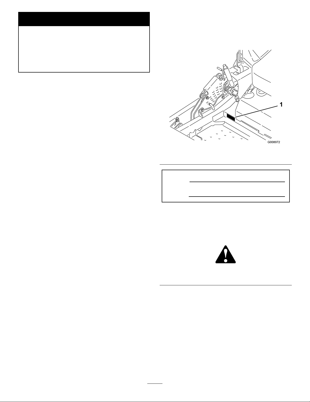
andserialnumbersofyourproductready.Figure1
identiesthelocationofthemodelandserialnumbers
ontheproduct.Writethenumbersinthespace
provided.
Figure1
1.Modelandserialnumberlocation
ModelNo.
SerialNo.
Thismanualidentiespotentialhazardsandhas
safetymessagesidentiedbythesafetyalertsymbol
Figure2),whichsignalsahazardthatmaycauseserious
(
injuryordeathifyoudonotfollowtherecommended
precautions.
Introduction
Thisrotary-blade,ridinglawnmowerisintendedtobe
usedbyresidentialhomeownersorprofessional,hired
operators.Itisdesignedprimarilyforcuttinggrasson
well-maintainedlawnsonresidentialorcommercial
properties.Itisnotdesignedforcuttingbrushorfor
agriculturaluses.
Readthisinformationcarefullytolearnhowtooperate
andmaintainyourproductproperlyandtoavoidinjury
andproductdamage.Youareresponsibleforoperating
theproductproperlyandsafely .
YoumaycontactTorodirectlyatwww.Toro.comfor
productandaccessoryinformation,helpndinga
dealer,ortoregisteryourproduct.
Wheneveryouneedservice,genuineToroparts,or
additionalinformation,contactanAuthorizedService
©2010—TheToro®Company
8111LyndaleAvenueSouth
Bloomington,MN55420
Figure2
1.Safetyalertsymbol
Thismanualuses2otherwordstohighlightinformation.
Importantcallsattentiontospecialmechanical
informationandNoteemphasizesgeneralinformation
worthyofspecialattention.
Contents
Introduction.................................................................2
Safety...........................................................................4
SafeOperatingPractices.......................................4
SlopeIndicator.....................................................6
Contactusatwww.T oro.com.
2
PrintedintheUSA.
AllRightsReserved
Page 3

SafetyandInstructionalDecals.............................7
ProductOverview......................................................12
Controls.............................................................12
Specications.....................................................13
Operation...................................................................14
AddingFuel.......................................................14
CheckingtheEngineOilLevel............................16
BreakingInaNewMachine................................16
UsingtheRolloverProtectionSystem
(ROPS)..........................................................17
ThinkSafetyFirst...............................................17
OperatingtheParkingBrake...............................18
OperatingtheMowerBladeControlSwitch
(PTO)............................................................19
OperatingtheThrottle.......................................19
OperatingtheIgnitionSwitch.............................19
StartingandStoppingtheEngine........................20
TheSafetyInterlockSystem................................21
DrivingForwardorBackward.............................22
StoppingtheMachine.........................................23
AdjustingtheHeightofCut................................23
AdjustingtheAnti-ScalpRollers.........................24
AdjustingtheFlowBafeCamLocks..................25
PositioningtheFlowBafe.................................25
PositioningtheSeat............................................26
UnlatchingtheSeat.............................................27
UsingtheDriveWheelReleaseValves.................27
UsingtheSideDischarge....................................27
TransportingMachines.......................................27
LoadingMachines..............................................28
OperatingTips...................................................29
Maintenance...............................................................31
RecommendedMaintenanceSchedule(s)................31
Lubrication.............................................................32
GreasingandLubrication...................................32
WheretoGreasetheMower...............................32
LubricateCasterWheelHubs.............................33
EngineMaintenance...............................................34
ServicingtheAirCleaner....................................34
ServicingtheEngineOil.....................................35
ServicingtheSparkPlug.....................................38
CheckSparkArrester(ifequipped)......................39
FuelSystemMaintenance.......................................40
InspectingtheLPGSystem.................................40
ElectricalSystemMaintenance................................41
ServicingtheBattery...........................................41
ServicingtheFuses.............................................43
DriveSystemMaintenance.....................................43
CheckingtheSeatBelt........................................43
CheckingtheRolloverProtectionSystem
(ROPS)Knobs...............................................43
AdjustingtheTracking........................................44
CheckingtheTirePressure.................................44
CheckingtheWheelHubSlottedNut..................45
AdjustingtheCasterPivotBearing......................45
UsingtheClutchShim........................................45
CoolingSystemMaintenance..................................47
CleaningtheEngineScreenandEngineOil
Cooler............................................................47
CleaningtheEngineCoolingFinsand
Shrouds..........................................................47
CheckandCleantheHydraulicUnit
Shrouds..........................................................48
BrakeMaintenance.................................................49
AdjustingtheParkingBrake................................49
BeltMaintenance....................................................50
InspectingtheBelts............................................50
ReplacingtheMowerBelt...................................50
ReplacingtheHydraulicPumpDrive
Belt................................................................51
ControlsSystemMaintenance.................................52
AdjustingtheControlHandlePosition................52
AdjustingtheMotionControlLinkage................52
AdjustingtheMotionControlDamper...............53
AdjustingtheMotionControlNeutralLock
Pivot..............................................................53
HydraulicSystemMaintenance...............................54
ServicingtheHydraulicSystem...........................54
MowerDeckMaintenance......................................56
LevelingtheMowerDeck...................................56
ServicingtheCuttingBlades...............................58
RemovingtheMowerDeck................................61
ReplacingtheGrassDeector.............................62
Cleaning.................................................................63
CleaningUndertheMower.................................63
WasteDisposal...................................................63
Storage.......................................................................63
CleaningandStorage..........................................63
Troubleshooting.........................................................65
Schematics.................................................................67
3
Page 4

Safety
Improperuseormaintenancebytheoperatororowner
canresultininjury.Toreducethepotentialforinjury,
complywiththesesafetyinstructionsandalwayspay
attentiontothesafetyalertsymbol,whichmeans
CAUTION,WARNING,orDANGER-“personal
safetyinstruction."Failuretocomplywiththe
instructionmayresultinpersonalinjuryordeath.
Thisproductiscapableofamputatinghandsand
feetandthrowingobjects.Alwaysfollowallsafety
instructionstoavoidseriousinjuryordeath.
Thisproductisdesignedforcuttingandrecyclinggrass
or,whenequippedwithagrassbagger,forcatching
cutgrass.Anyuseforpurposesotherthanthesecould
provedangeroustouserandbystanders.
SafeOperatingPractices
ThefollowinginstructionsarefromANSIstandard
B71.4-2004.
Training
•ReadtheOperator’sManualandothertraining
material.Iftheoperator(s)ormechanic(s)cannot
readEnglishitistheowner’sresponsibilitytoexplain
thismaterialtothem.
•Becomefamiliarwiththesafeoperationofthe
equipment,operatorcontrols,andsafetysigns.
•Alloperatorsandmechanicsshouldbetrained.The
ownerisresponsiblefortrainingtheusers.
•Neverletchildrenoruntrainedpeopleoperateor
servicetheequipment.Localregulationsmayrestrict
theageoftheoperator.
•Theowner/usercanpreventandisresponsiblefor
accidentsorinjuriesoccurringtohimselforherself,
otherpeopleorproperty.
Preparation
•Evaluatetheterraintodeterminewhataccessories
andattachmentsareneededtoproperlyand
safelyperformthejob.Onlyuseaccessoriesand
attachmentsapprovedbythemanufacturer.
•Wearappropriateclothingincludinghardhat,safety
glassesandhearingprotection.Longhair,loose
clothingorjewelrymaygettangledinmovingparts.
•Inspecttheareawheretheequipmentistobeused
andremoveallobjectssuchasrocks,toysandwire
whichcanbethrownbythemachine.
•UseextracarewhenhandlingLPGfuel(liqueed
petroleumgas).Thevaporsareammableand
explosive.
–Useonlyanapprovedtank
–Neverrefuelthemachineindoors.
–LPGbecomesammablewhenitismixedwith
air.
–Neverremovethetankwithenginerunning.
Allowenginetocoolbeforerefueling.Donot
smoke.
•Checkthatoperator’spresencecontrols,safety
switchesandshieldsareattachedandfunctioning
properly.Donotoperateunlesstheyarefunctioning
properly.
Operation
•Lightningcancausesevereinjuryordeath.If
lightningisseenorthunderisheardinthearea,do
notoperatethemachine;seekshelter.
•Neverrunanengineinanenclosedarea.
•Onlyoperateingoodlight,keepingawayfromholes
andhiddenhazards.
•Besurealldrivesareinneutralandparkingbrakeis
engagedbeforestartingengine.Starttheengineonly
fromtheoperator’sposition.Useseatbelts.
•Neverraisemowerwiththebladesrunning.
•NeveroperatewithoutthePTOshield,orother
guardssecurelyinplace.Besureallinterlocksare
attached,adjustedproperly ,andfunctioningproperly.
•Neveroperatewiththedischargedeectorraised,
removedoraltered,unlessusingagrasscatcher.
•Donotchangetheenginegovernorsettingor
overspeedtheengine.
•Stoponlevelground,lowerimplements,disengage
drives,engageparkingbrake,shutoffenginebefore
leavingtheoperator’spositionforanyreason
includingemptyingthecatchersoruncloggingthe
chute.
•Stopequipmentandinspectbladesafterstriking
objectsorifanabnormalvibrationoccurs.Make
necessaryrepairsbeforeresumingoperations.
•Keephandsandfeetawayfromthecuttingunits.
•Nevercarrypassengersandkeeppetsandbystanders
away.
•Bealert,slowdownandusecautionwhenmaking
turns.Lookbehindandtothesidebeforechanging
directions.
•Slowdownandusecautionwhencrossingroadsand
sidewalks.Stopbladesifnotmowing.
4
Page 5

•Beawareofthemowerdischargedirectionanddo
notpointitatanyone.
•Donotoperatethemowerundertheinuenceof
alcoholordrugs.
•Useextremecarewhenloadingorunloadingthe
machineintoatrailerortruck.
•Usecarewhenapproachingblindcorners,shrubs,
trees,orotherobjectsthatmayobscurevision.
SlopeOperation
•Donotmowslopesgreaterthan15degrees.
•Donotmowneardrop-offs,ditches,steepbanks
orwater.Wheelsdroppingoveredgescancause
rollovers,whichmayresultinseriousinjury,death
ordrowning.
•Donotmowslopeswhengrassiswet.Slippery
conditionsreducetractionandcouldcausesliding
andlossofcontrol.
•Donotmakesuddenturnsorrapidspeedchanges.
•Useawalkbehindmowerand/orahandtrimmer
neardrop-offs,ditches,steepbanksorwater.
•Reducespeedanduseextremecautiononslopes.
•Removeormarkobstaclessuchasrocks,treelimbs,
etc.fromthemowingarea.Tallgrasscanhide
obstacles.
•Watchforditches,holes,rocks,dips,andrisesthat
changetheoperatingangle,asroughterraincould
overturnthemachine.
•Avoidsuddenstartswhenmowinguphillbecause
themowermaytipbackwards.
•Beawarethatoperatingonwetgrass,acrosssteep
slopes,ordownhillmaycausethemowertolose
traction.Lossoftractiontothedrivewheelsmay
resultinslidingandalossofbrakingandsteering.
•Alwaysavoidsuddenstartingorstoppingona
slope.Iftireslosetraction,disengagethebladesand
proceedslowlyofftheslope.
•Followthemanufacturer’srecommendationsfor
wheelweightsorcounterweightstoimprovestability.
•Useextremecarewithgrasscatchersorother
attachments.Thesecanchangethestabilityofthe
machineandcauselossofcontrol.
UsingtheRolloverProtectionSystem
(ROPS)
•Keeptherollbarintheraisedandlockedposition
andusetheseatbeltwhenoperatingthemachine.
•Becertainthattheseatbeltcanbereleasedquickly
intheeventofanemergency.
•Beawarethereisnorolloverprotectionwhenthe
rollbarisdown.
•Checktheareatobemowedandneverfoldthe
ROPSinareaswherethereareslopes,dropoffsor
water.
•Lowertherollbaronlywhenabsolutelynecessary.
Donotweartheseatbeltwiththerollbarfolded
down.
•Checkcarefullyforoverheadclearances(i.e.
branches,doorways,electricalwires)beforedriving
underanyobjectsanddonotcontactthem.
Maintenanceandstorage
•Disengagedrives,lowerimplement,setparking
brake,stopengineandremovekeyordisconnect
sparkplugwire.Waitforallmovementtostop
beforeadjusting,cleaningorrepairing.
•Cleangrassanddebrisfromcuttingunits,drives,
mufers,andenginetohelppreventres.Cleanup
oilorfuelspillage.
•Letenginecoolbeforestoringanddonotstorenear
ame.
•Shutofffuelwhilestoringortransporting.Donot
storefuelnearamesordrainindoors.
•Parkmachineonlevelground.Neverallowuntrained
personneltoservicemachine.
•Usejackstandstosupportcomponentswhen
required.
•Carefullyreleasepressurefromcomponentswith
storedenergy.
•Disconnectbatteryorremovesparkplugwirebefore
makinganyrepairs.Disconnectthenegativeterminal
rstandthepositivelast.Reconnectpositiverst
andnegativelast.
•Usecarewhencheckingblades.Wraptheblade(s)or
weargloves,andusecautionwhenservicingthem.
Onlyreplacedamagedblades;neverstraightenor
weldthem.
•Keephandsandfeetawayfrommovingparts.If
possible,donotmakeadjustmentswiththeengine
running.
•Chargebatteriesinanopenwellventilatedarea,
awayfromsparkandames.Unplugchargerbefore
connectingordisconnectingfrombattery.Wear
protectiveclothinganduseinsulatedtools.
•Keepallpartsingoodworkingconditionandall
hardwaretightened.Replaceallwornordamaged
decals.
•UseonlyToroapprovedattachments.Warrantymay
bevoidedifusedwithunapprovedattachments.
5
Page 6
SlopeIndicator
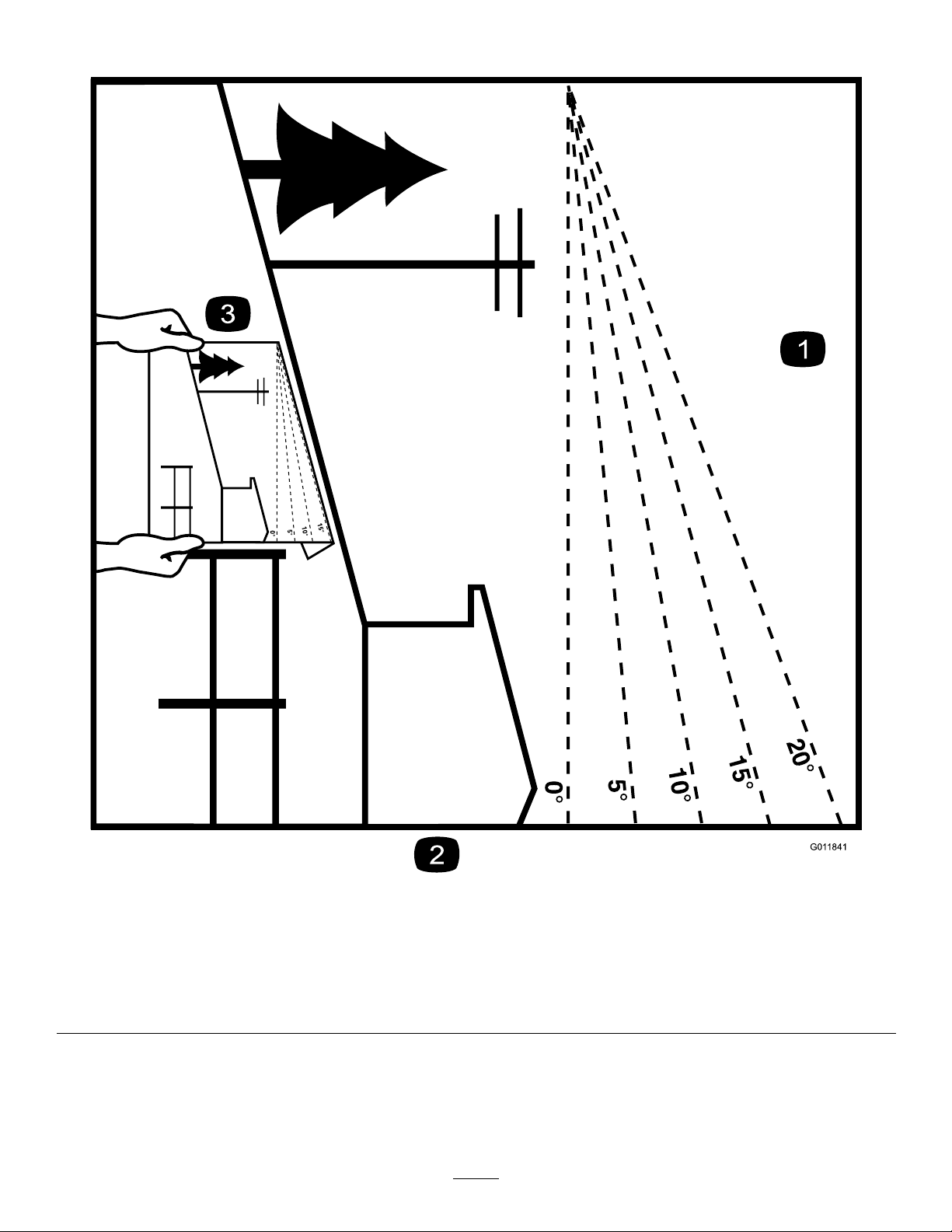
G011841
Figure3
Thispagemaybecopiedforpersonaluse.
1.Themaximumslopeyoucansafelyoperatethemachineonis15degrees.Usetheslopecharttodeterminethedegreeofslope
ofhillsbeforeoperating.Donotoperatethismachineonaslopegreaterthan15degrees.Foldalongtheappropriateline
tomatchtherecommendedslope.
2.Alignthisedgewithaverticalsurface,atree,building,fencepole,etc.
3.Exampleofhowtocompareslopewithfoldededge.
6
Page 7

SafetyandInstructional
Decals
Safetydecalsandinstructionsareeasilyvisibletotheoperatorandarelocatednearanyareaof
potentialdanger.Replaceanydecalthatisdamagedorlost.
68-8340
1-403005
98-5954
103-2076
54-9220
58-6520
1.Grease
105-7798
66-1340
7
Page 8
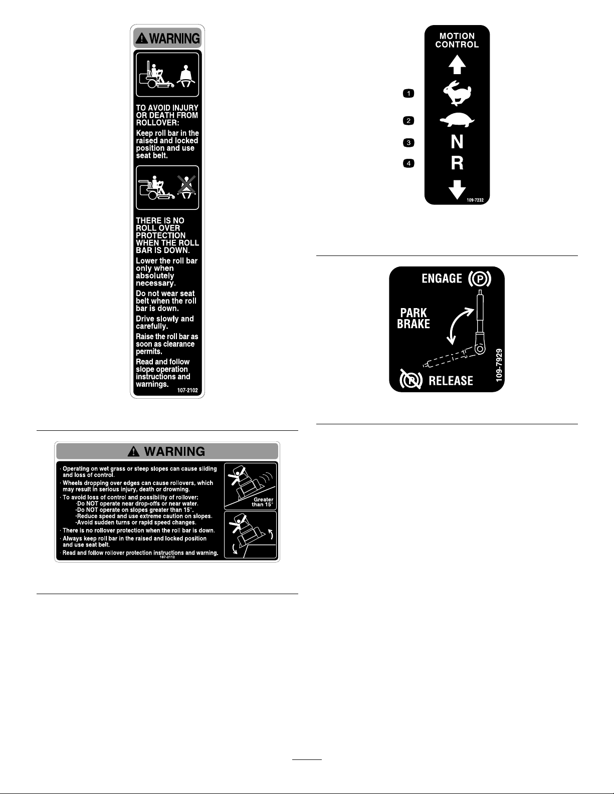
109-7232
1.Fast3.Neutral
2.Slow
4.Reverse
107-2102
107-2112
109-7929
8
Page 9
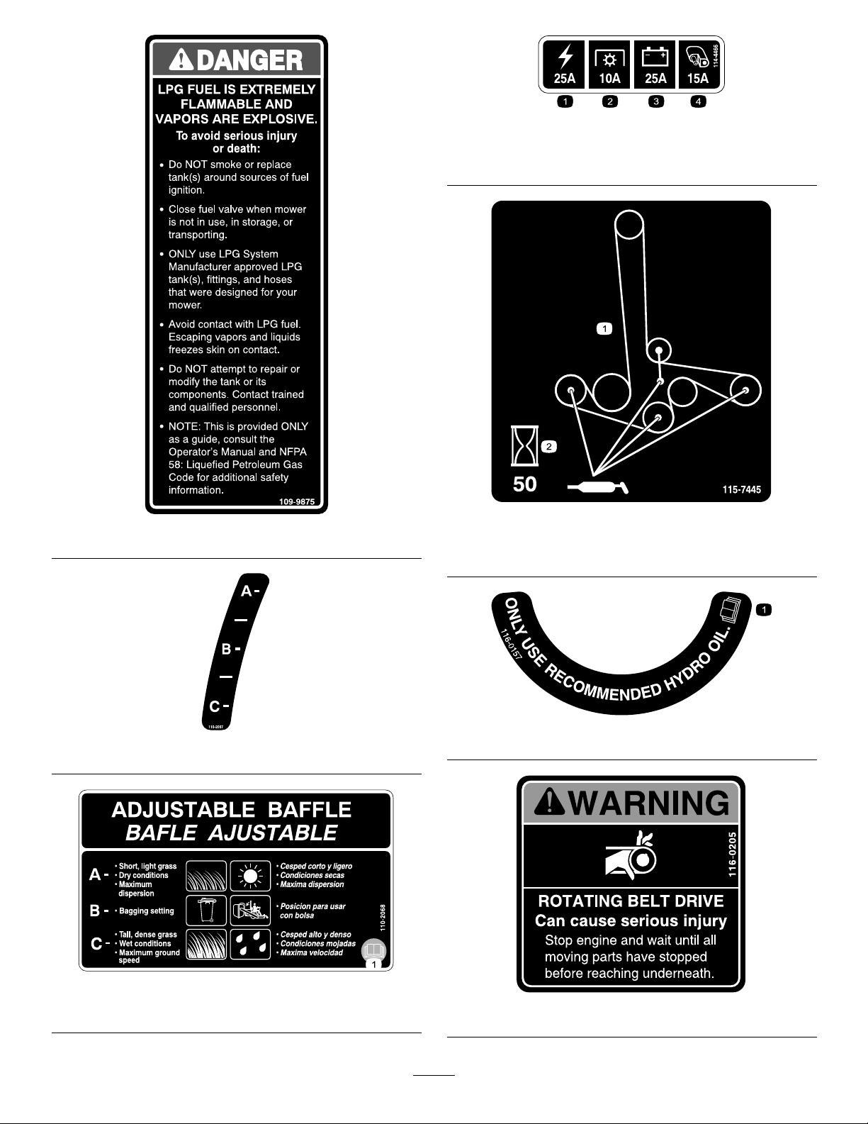
1.Main,25A
2.PTO,10A
114-4466
3.Charge,25A
4.Auxiliary,15A
109-9875
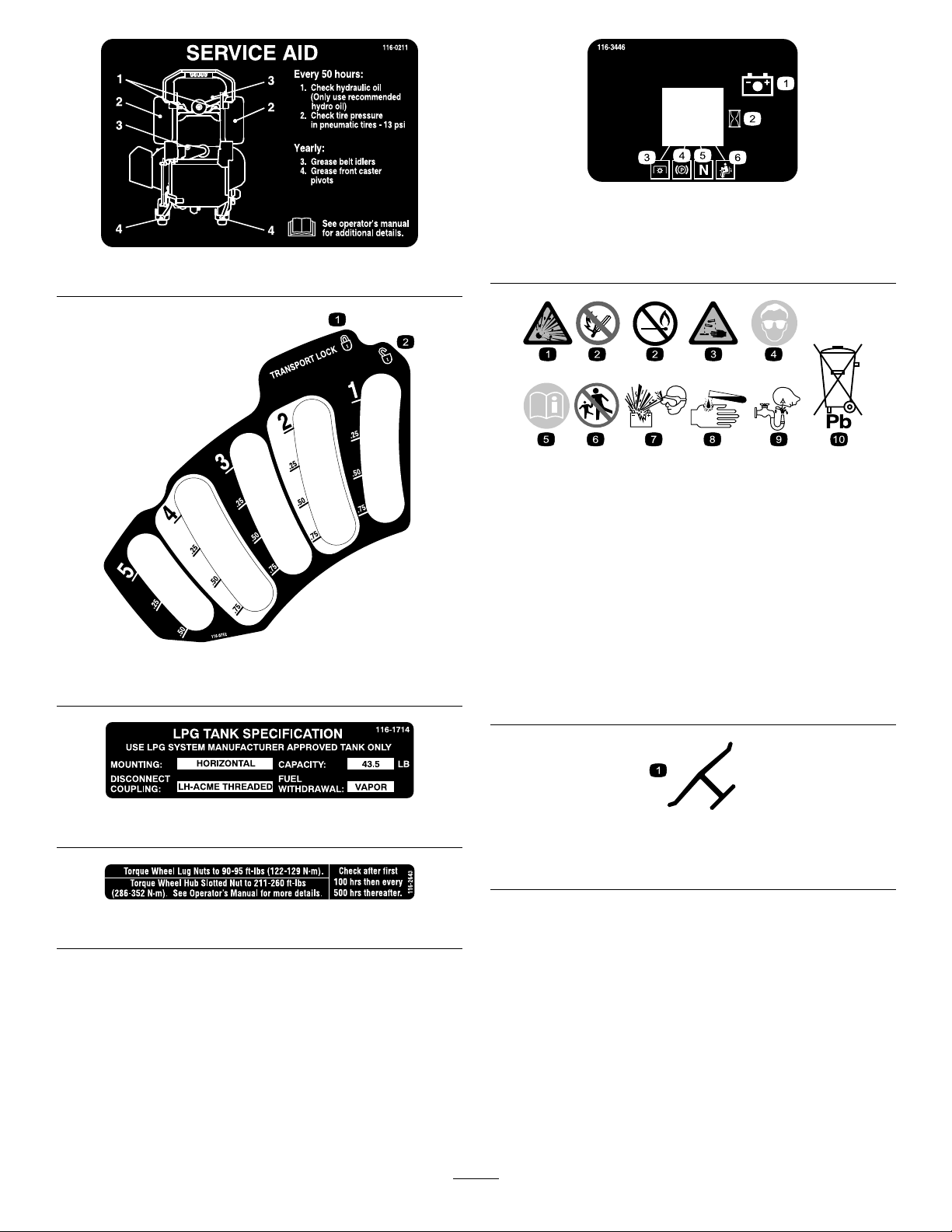
1.Greasepulleysandspindles
2.Maintenanceinterval—50hours
116-0157
110-2067
115-7445
110-2068
1.ReadtheOperator’sManual.
116-0205
9
Page 10
1.Locked2.Unlocked
116-0211
116-0752
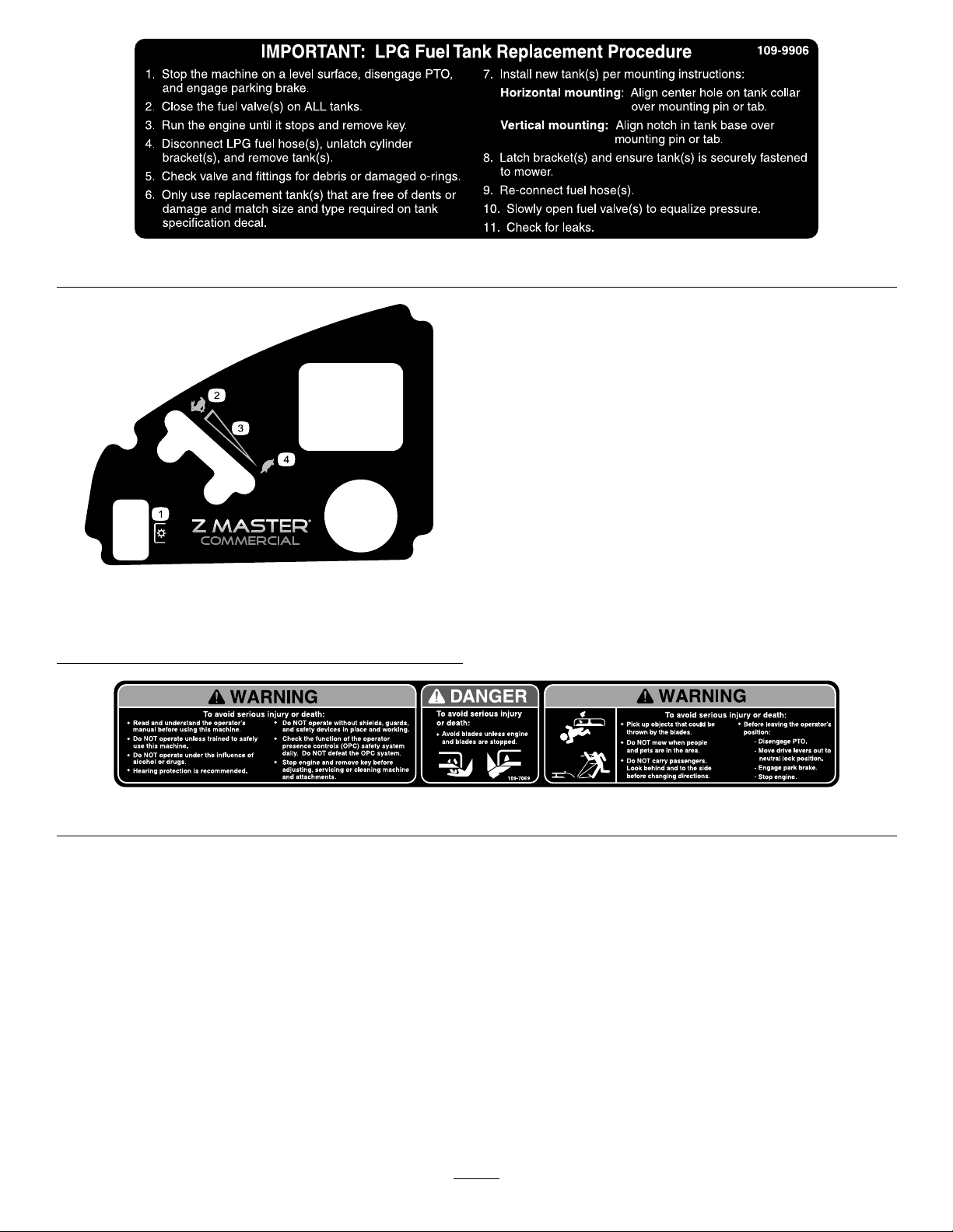
116-3446
1.Battery4.Parkingbrake
2.Hourmeter5.Neutral
3.PTO6.Operatorpresenceswitch
BatterySymbols
Someorallofthesesymbolsareonyourbattery
1.Explosionhazard
2.Nore,opename,or
smoking.
3.Causticliquid/chemical
burnhazard
4.Weareyeprotection9.Flusheyesimmediately
5.ReadtheOperator’s
Manual.
6.Keepbystandersasafe
distancefromthebattery.
7.Weareyeprotection;
explosivegasescan
causeblindnessandother
injuries
8.Batteryacidcancause
blindnessorsevereburns.
withwaterandgetmedical
helpfast.
10.Containslead;donot
discard.
116-1714
1.Indicatesthebladeisidentiedasapartfromtheoriginal
machinemanufacturer.
Manufacturer’sMark
116-2643
10
Page 11
119-4233
1.PowerT ake-off(PTO)3.Continuousvariable
2.Fast
setting
4.Slow
109-9906
109-7069
11
Page 12

ProductOverview
g013436
7
6
5
4
3
2
1
8
9
10
g013663
25
25
10
15
1
2
3
4
5
Figure4
1.Height-of-cutdecklift
pedal
2.Transportlock7.Rollbar
3.Parkingbrakelever8.Motioncontrollevers
4.Controls9.Casterwheel
5.Seatbelt
6.Fueltank
10.Mowerdeck
HourMeter
Thehourmeterrecordsthenumberofhourstheengine
hasoperated.Itoperateswhentheengineisrunning.
Usethesetimesforschedulingregularmaintenance
Figure6).
(
FuelGauge
LocatedontheLPGfueltank.
ThisgaugemonitorstheamountofliquidLPGinthe
fueltank.
SafetyPressureReliefValve
LocatedontheLPGfueltank.
Thesafetypressurereliefvalverelievestheexcess
pressureintheLPGtank.
Important:Thisvalvehasaprotectiveplasticcap
thatshouldNEVERberemoved.Ifthecapis
damagedormissing,contacttrainedandqualied
personnelimmediately.
LPGCylinderBrackets
Thebracketsarelocatedontheenginedeck.
TheLPGcylinderbracketsareusedtofastenthe
removableLPGtanktothemower.
SafetyInterlockIndicators
Controls
Becomefamiliarwithallthecontrolsbeforeyoustartthe
engineandoperatethemachine(Figure4andFigure5).
Therearesymbolsonthehourmeterandtheindicate
withablacktrianglethattheinterlockcomponentisin
thecorrectposition(Figure6).
BatteryIndicatorLight
IftheignitionkeyisturnedtotheOnpositionforafew
1.PTOSwitch
2.Throttlecontrol5.Fuses
3.Hourmeter/Safety
interlockdisplay
Figure5
4.Ignitionswitch
seconds,thebatteryvoltagewillbedisplayedinthearea
wherethehoursarenormallydisplayed.
Thebatterylightturnsonwhentheignitionisturned
onandwhenthechargeisbelowthecorrectoperating
Figure6).
level(
12
Page 13
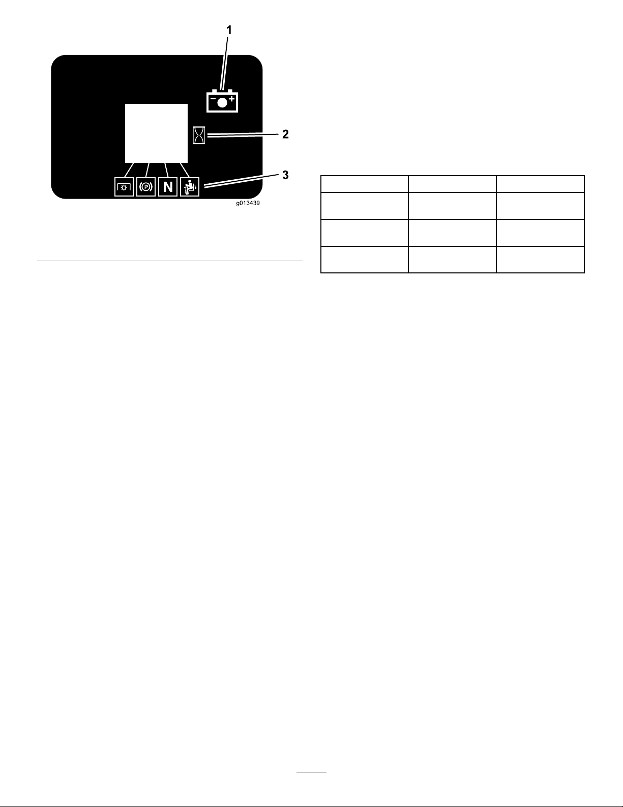
g013439
1
2
3
Figure6
1.Batterylight
2.Hourmeter
3.Safetyinterlocksymbols
ThrottleControl
ThethrottlecontrolisvariablebetweenFastandSlow.
enhanceandexpanditscapabilities.Contactyour
AuthorizedServiceDealerorDistributororgoto
www.T oro.comforalistofallapprovedattachments
andaccessories.
Specications
Note:Specicationsanddesignaresubjecttochange
withoutnotice.
Width:
60inchDeck72inchDeck
WithoutDeck
DeectorUp61.73inches(156.8
DeectorDown75.67inches(192.2
53.0inches(134.6
cm)
cm)
cm)
59.1inches(150.1
cm)
73.61inches(187
cm)
87.55inches(222.4
cm)
BladeControlSwitch(PTO)
Thebladecontrolswitch(PTO)isusedtoengagethe
electricclutchanddrivethemowerblades.Pullthe
switchuptoengagethebladesandrelease.Todisengage
theblades,pushthebladecontrolswitch(PTO)down
ormoveamotioncontrolleverintotheneutrallock
position.
IgnitionSwitch
Thisswitchisusedtostartthemowerengineandhas
threepositions:Start,RunandOff.
MotionControlLevers
Themotioncontrolleversareusedtodrivethemachine
forward,reverse,andturneitherdirection.
NeutralLockPosition
Theneutrallockpositionisusedwiththesafetyinterlock
systemtoengageandtodetermineneutralposition.
FuelShut-offValve
Closethefuelshut-offvalveonthecylindertankwhen
transportingorstoringthemower.
Attachments/Accessories
AselectionofToroapprovedattachmentsand
accessoriesareavailableforusewiththemachineto
13
Page 14

Length:
RollBar-Up
RollBar-Down
60inchDeck72inchDeck
83.1inches(211.1
cm)
84.8inches(215.4
cm)
86.1inches(218.7
cm)
87.8inches(223.0
cm)
Operation
Note:Determinetheleftandrightsidesofthe
machinefromthenormaloperatingposition.
AddingFuel
Height:
RollBar-UpRollBar-Down
70.5inches(179.1cm)46.8inches(1 18.9cm)
Weight:
60inchDeck72inchDeck
29HPKawasaki
Units
1255lb(569kg)1350lb(612kg)
TankTypeandRelling
Note:TheLPGtankusedonthismowerisaspecial
tankwithinternalbafesdesignedforthisapplication.
•HorizontalTankSpecications:
–TankMaterial:Aluminum
–Capacity:43.5lb
–Disconnectcoupling:LefthandACMEthreaded
–FuelWithdrawal:Vapor
–FuelShut-OffValve:Rotateclockwisetoclose.
–Typeoffuel:HD5gradepropane
WhatisLPG?LPGstandsforliqueedpetroleumgas
andismorecommonlycalledpropane.LPGisaliquid
fuelthatisstoredinatankunderpressure.Beforethe
liquidleavesthetank,itisconvertedintoavapor.Since
LPGisstoredasbothliquidandgas,itmayleakfrom
jointsorconnectionsthatarenotsealedproperly.LPG
becomesammablewhenitismixedwithair.
TheLPGinformationinthisOperator’smanualis
providedonlyasaguide.ConsulttheNFPA58:
LiqueedPetroleumGasCode,2008Editionfor
additionalsafetyinformation.ThisNationalFire
ProtectionAssociation(NFPA)codepertainstothe
handling,storing,transporting,andusageofLPG.
Typeoffuel:HD5gradepropane
CAUTION
Undernocircumstancesshouldpropanetanks
lledbeyond80%capacitybeusedinservice.
Theuseofoverlledtanksmayresultintherelease
ofhighlyconcentratedandextremelyammable
liquidpropane.RefertotheSafetysection.
•Newtanksmustbeproperlylledbytrainedand
qualiedpersonnel.
•OnlyusetanksrecommendedbyToro.Failureto
dosowillresultinimproperoperationofthefuel
system.
Note:Useofa“forklift”typeliquidwithdrawaltank
willresultinicingorfreezingoftheLPGregulatorand
preventtheenginefromoperating.Thismayalsoresult
inpermanentfuelsystemdamageandthereleaseof
highlyammablepropaneliquidorvapor.
14
Page 15

DANGER
DANGER
LPGfuelisextremelyammableandvaporsare
explosive.
AreorexplosionfromLPGfuelcanburnyou,
others,andcausepropertydamage.
•Neversmokearoundtank(s)andstayaway
fromanopenameorwherefumesmaybe
ignitedbyaspark.
•Extinguishallsourcesofsparkoramewhen
approachingLPGtanksormowers.The
hazardincreasesforenclosedtrailersorstorage
locationswherevaporleakagemayoccurand
collect.
•LPGisheavierthanairandmayaccumulatein
lowlyingareas,suchasditches,drains,orpits.
•LPGtank(s)shouldbelledbytrainedand
qualiedpersonnelONLY .
•Nevertamperwithorrepairthetank(s);contact
trainedandqualiedpersonnel.
•DoNotchangethetank(s)whentheengineis
running.
•Beforedisconnectingthehose(s),purgeall
LPGvaporsfromthesystem,byclosingthefuel
valve(s)onALLtanksandallowingtheengine
torununtilitstops.
•Storethetank(s)awayfromheat,sparks,or
openames.
•DoNotoperatewithoutentireexhaustsystem
inplaceandinproperworkingcondition.
DANGER
LPGvaporsandliquidescapingfromthetankmay
causeseriousinjuryordeath.V aporsorliquidmay
causesuffocation,freezingoftissue,orfrostbite.
•Storeandservicethemowerinawellventilated
area.
•AnapprovedLPGdetectorinstalledintrailers
andstorageareasisrecommended.
•LPGisheavierthanairandmayaccumulatein
lowlyingareas,suchasditches,drains,orpits.
•Avoidbreathingofvapors.
•Keepawayfromventvalve.
•Keepawayfromeyesandskin.
•Contacttrainedandqualiedpersonneliftank
showssignsoffrostedareas,makesahissing
sound,oremitsafoulodor.
•Obtainimmediatemedicalattentionifcontact
occurswithvaporsorliquid.
LPGfuelisextremelyammableandvaporsare
explosive.
•Incaseofretakethefollowingsteps:
1.Ifyoucansafelydoso,stoptheowofgas
asquicklyaspossible.Neverputoutame
unlessgascanbeshutoff.
2.NotifytheFireDepartmentandclear
immediateareaofallpeople.
3.Whengasowisstopped,putoutthere.
Usuallywhenowofgasiscutoff,rewill
automaticallystop.
4.Ifgasowcannotbeimmediatelystopped,
directwaterontankstokeepthemcool,but
DoNotputoutre.
•Storagelocationsandtrailersshouldbe
equippedwithatleastoneapprovedportable
reextinguisherhavingaminimumcapacityof
18lb(8.2kg)drychemicalwithaB:Crating.
DoNotuseCarbonTetrachlorideextinguishers
(Pyreneetc.).
ChangingtheLPGTank
ChangetheLPGtankoutdoorsinawellventilatedarea.
Important:Onlyhandtightentankconnection
tting.Overtighteningbytheuseoftoolsmay
causedamage.Ifhandtighteningdoesnotstop
aleak,contacttrainedandqualiedpersonnel
immediately.
1.Stopthemachineonlevelground,disengagethe
bladecontrolswitch(PTO),movethemotion
controlleverstotheneutrallockedpositionandset
theparkingbrake.
2.Waitforallmovingpartsforthemowerdeckto
stopbeforeleavingtheoperatingposition.
3.Withtheenginerunning,closethefuelvalveonthe
tank.
4.Runtheengineuntilitstops.Thispurgesallvapors
fromthehose.
5.Removethekey.
6.CarefullydisconnecttheLPGfuelhose.
15
Page 16
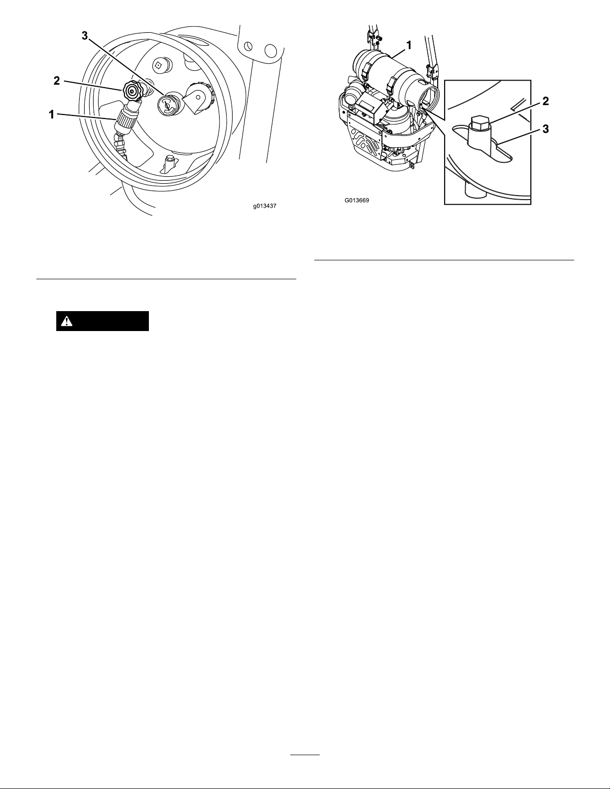
g013437
1
2
3
Figure7
G013669
1.LPGfuelhoseconnection
tting
2.Tankvalve
3.Fuelgauge
7.Unlatchthecylinderbracketsandremovethetank.
Figure8
1.Cylinderbrackets3.Centerhole
2.Mountingpin
Important:V alvesandgaugesmaynot
functionproperlyiftheLPGtankisnot
installedcorrectly.
WARNING
Fuelsystemcomponentsareunderhigh
pressure.Theuseofdamagedorimproper
componentscancausesystemfailure,fuel
leakage,andpossibleexplosion,whichmay
resultinseriousinjuryordeath.
•DoNotattempttorepairormodifythe
valves,ttings,orothertankcomponents.
•ONLYusetheToroapprovedLPGtank,
ttings,andhosesthatweredesignedfor
yourmower.
12.Latchthecylinderbracketsandmakesurethetank
issecurelyfastenedtothemower.
13.Carefullyconnectthefuelhose.Makesurethehose
isnotkinked.
14.Slowlyopenthefuelvalvetoequalizethepressurein
thetank.Ifthefuelvalveisopenedtooquickly,the
pressurereliefvalveisequippedwithabackpressure
checkvalvethatwillshutoffthefuelsupply.Ifthis
happens,closethefuelvalvecompletelyandwait
veseconds.Slowlyopenthefuelvalve.
15.CheckforleaksasdescribedintheInspection
section.
8.Inspectthelledtankvalveandttingopeningsfor
dirt,debris,ordamage.
CheckingtheEngineOilLevel
9.Inspectthetankhoseconnectionttingfor
damagedormissingo-rings.
10.Makesurethereplacementtanktypeandsizematch
thetankspecicationdecal.
11.Alignthecenterholeoverthemountingpinthat
pointsstraightuponthemowerasshownin
Figure8.
Beforeyoustarttheengineandusethemachine,check
theoillevelintheenginecrankcase;refertoChecking
theEngineOilLevel.
BreakingInaNewMachine
Newenginestaketimetodevelopfullpower.Mower
decksanddrivesystemshavehigherfrictionwhennew,
placingadditionalloadontheengine.Allow40to50
hoursofbreak-intimefornewmachinestodevelopfull
powerandbestperformance.
16
Page 17
UsingtheRolloverProtection
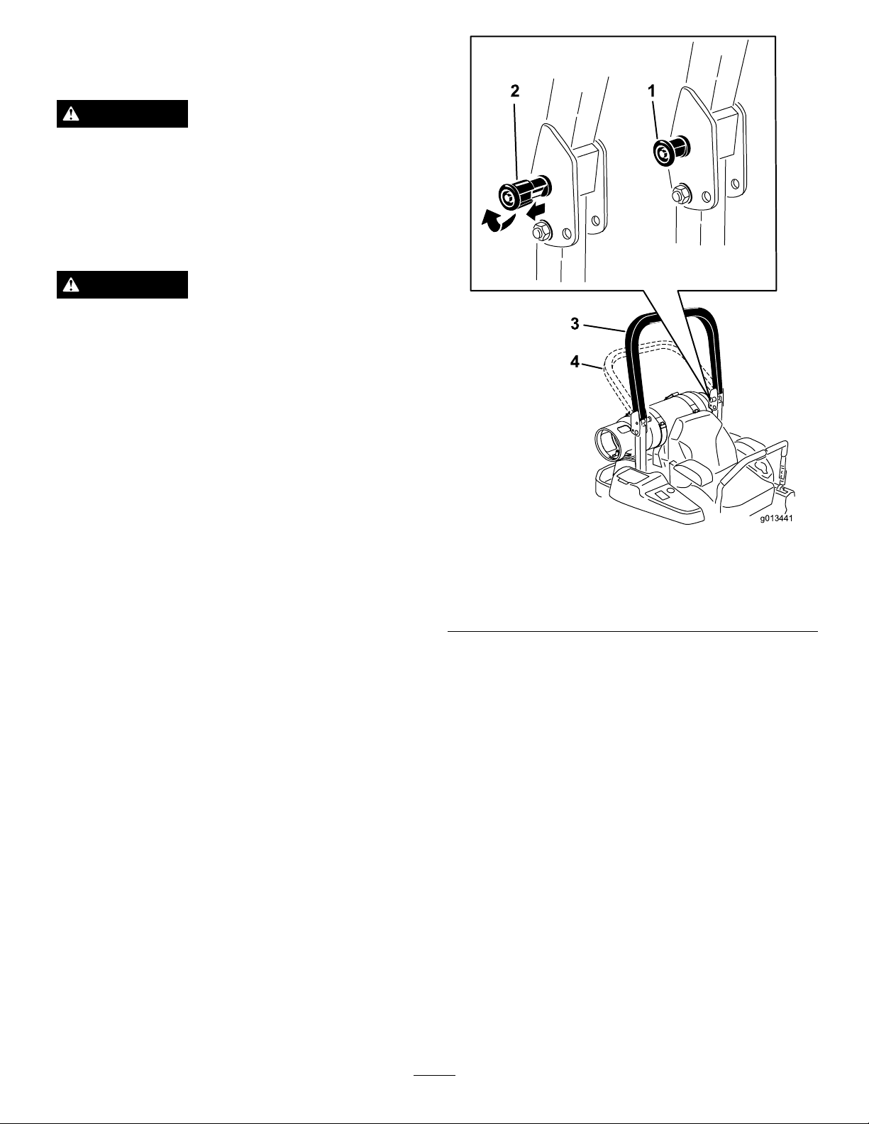
g013441
2 1
3
4
System(ROPS)
WARNING
Toavoidinjuryordeathfromrollover:keepthe
rollbarintheraisedlockedpositionandusethe
seatbelt.
Ensurethattherearpartoftheseatissecuredwith
theseatlatch.
WARNING
Thereisnorolloverprotectionwhentherollbar
isinthedownposition.
•Lowertherollbaronlywhenabsolutely
necessary.
•Donotweartheseatbeltwhentherollbaris
inthedownposition.
•Driveslowlyandcarefully.
•Raisetherollbarassoonasclearancepermits.
•Checkcarefullyforoverheadclearances(i.e.
branches,doorways,electricalwires)before
drivingunderanyobjectsanddonotcontact
them.
Important:Lowertherollbaronlywhen
absolutelynecessary .
Important:Ensurethattherearpartoftheseatis
securedwiththeseatlatch.
1.Tolowertherollbar,applyforwardpressuretothe
upperpartoftherollbar.
2.Pullbothknobsoutandrotatethem90°sotheyare
notengaged(
3.Lowertherollbartothedownposition(
Figure9).
Figure9).
Figure9
1.ROPSknob
2.PullROPSknoboutand
rotate90degrees
3.Rollbarintheupright
position
4.Rollbarinthefolded
position
4.Toraisetherollbar,raisetherollbartotheoperate
position,rotatetheknobssotheymovepartially
intothegrooves(
Figure9).
5.Raisetherollbartothefulluprightpositionwhile
pushingontheupperrollbarandthepinswillsnap
intopositionwhentheholesalignwiththepins
Figure9).Pushontherollbarandensurethat
(
bothpinsareengaged.
Important:Alwaysusetheseatbeltwiththe
rollbarintheraisedposition.
ThinkSafetyFirst
Pleasereadallsafetyinstructionsandsymbolsinthe
safetysection.Knowingthisinformationcouldhelp
youorbystandersavoidinjury.
17
Page 18
DANGER
G009027
1
2
G008960
1
2
CAUTION
Operatingonwetgrassorsteepslopescancause
slidingandlossofcontrol.
Wheelsdroppingoveredgescancauserollovers,
whichmayresultinseriousinjury,deathor
drowning.
Thereisnorolloverprotectionwhentherollbar
isdown.
Alwayskeeptherollbarintheraisedandlocked
positionandusetheseatbelt.
Readandfollowtherolloverprotectioninstructions
andwarnings.
Toavoidlossofcontrolandpossibilityofrollover:
•Donotoperateneardrop-offsornearwater.
•Donotoperateonslopesgreaterthan
15degrees.
•Reducespeedanduseextremecautionon
slopes.
•Avoidsuddenturnsorrapidspeedchanges.
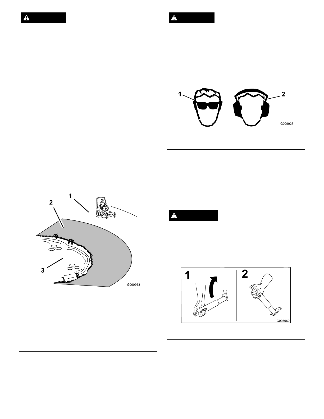
Thismachineproducessoundlevelsinexcessof
85dBAattheoperatorsearandcancausehearing
lossthroughextendedperiodsofexposure.
Wearhearingprotectionwhenoperatingthis
machine.
Theuseofprotectiveequipmentforeyes,ears,feetand
headisrecommended.
Figure11
1.Wearsafetyglasses
2.Wearhearingprotection
OperatingtheParkingBrake
Alwayssettheparkingbrakewhenyoustopthe
machineorleaveitunattended.
1.SafeZone-usethe
ZMasterhereonslopes
lessthan15degreesor
atareas.
2.DangerZone-useawalk
behindmowerand/ora
handtrimmeronslopes
greaterthan15degrees,
neardrop-offsandwater.
SettingtheParkingBrake
WARNING
Parkingbrakemaynotholdmachineparkedona
slopeandcouldcausepersonalinjuryorproperty
damage.
Donotparkonslopesunlesswheelsarechocked
orblocked
Figure10
3.Water
Figure12
ReleasingtheParkingBrake
Pushinthereleasebuttonbeforepushingdown.
18
Page 19
G008944
1
2
3
G008945
DisengagingtheBladeControlSwitch
G009174
G008946
(PTO)
Figure15
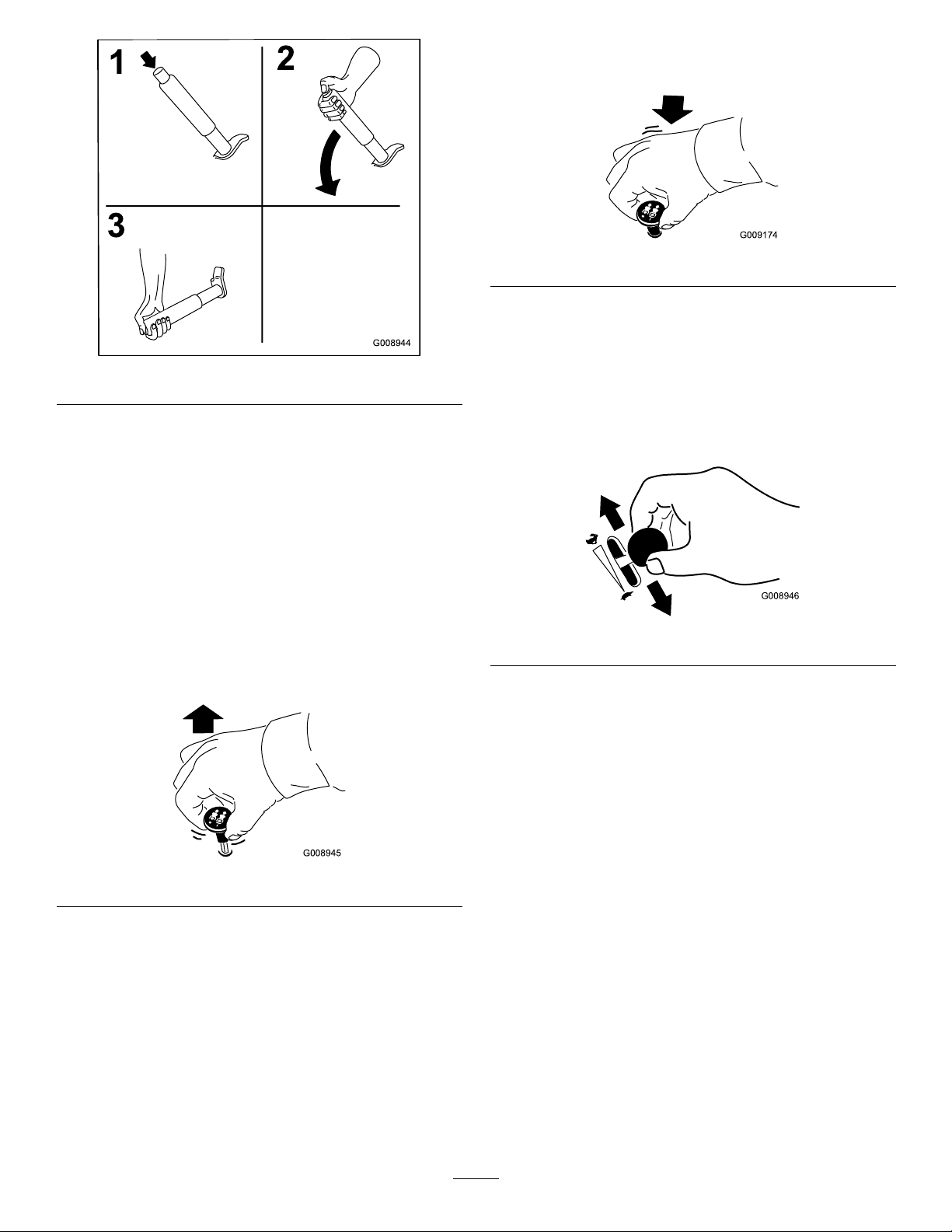
OperatingtheThrottle
Figure13
OperatingtheMowerBlade
ControlSwitch(PTO)
Thebladecontrolswitch(PTO)startsandstopsthe
mowerbladesandanypoweredattachments.
EngagingtheBladeControlSwitch
(PTO)
Note:Engagingthebladecontrolswitch(PTO)with
thethrottlepositionathalforlesswillcauseexcessive
weartothedrivebelts.
Figure14
ThethrottlecontrolcanbemovedbetweenFastand
Slowpositions(Figure16).
Alwaysusethefastpositionwhenturningonthe
mowerdeckwiththebladecontrolswitch(PTO).
Figure16
OperatingtheIgnitionSwitch
1.TurntheignitionkeytotheStartposition
(Figure17).Whentheenginesstarts,releasethekey .
Important:Donotengagestarterformore
than5secondsatatime.Iftheenginefails
tostartallowa15secondcool-downperiod
betweenattempts.Failuretofollowthese
instructionscanburnoutthestartermotor.
Note:Additionalstartingcyclesmayberequired
whenstartingtheengineforthersttimeafterthe
fuelsystemhasbeenwithoutfuelcompletely.
19
Page 20

START
RUN
STOP
G008947
Figure17
g013505
6
START
RUN
STOP
G008947
2.Turntheignitionkeytostoptostoptheengine.
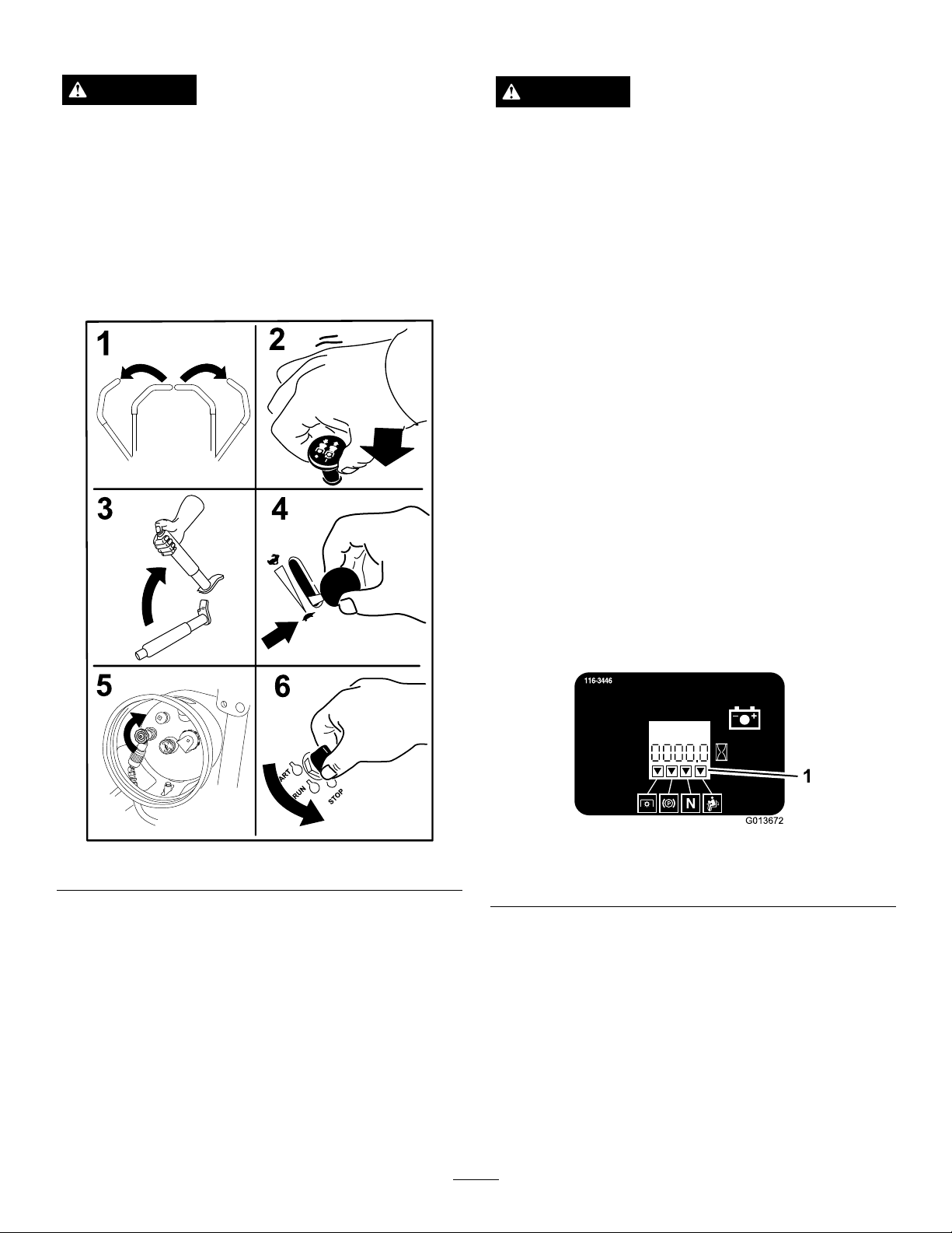
StartingandStoppingthe
Engine
StartingtheEngine
1.RaisetheROPSupandlockintoplace,sitonthe
seatandfastentheseatbelt.
2.Slowlyopenthefuelvalvetoequalizethepressure
inthetank.Thefuelvalveislocatedonthetopend
oftheLPGtank.Ifthefuelvalveisopenedtoo
quickly,thepressurereliefvalveisequippedwith
abackpressurecheckvalvethatwillshutoffthe
fuelsupply .Ifthishappens,closethefuelvalve
completelyandwaitveseconds.Slowlyopenthe
fuelvalve.
3.Movethemotioncontrolstoneutrallocked
position.
4.Settheparkingbrake;refertoSettingtheParking
Brake.
5.Movethebladecontrolswitch(PTO)totheOff
position(
Figure18).
Figure18
7.TurntheignitionkeytotheStartposition
(Figure17).Whentheenginesstarts,releasethekey .
Important:Donotengagestarterformore
than5secondsatatime.Iftheenginefails
tostartallowa15secondcool-downperiod
betweenattempts.Failuretofollowthese
instructionscanburnoutthestartermotor.
Note:Additionalstartingcyclesmayberequired
whenstartingtheengineforthersttimeafterthe
fuelsystemhasbeenwithoutfuelcompletely.
6.Movethethrottlelevertothe3/4throttleposition
betweentheSlowandFastpositions(
Figure18).
Figure19
1.Off3.Start
2.Run
20
Page 21
StoppingtheEngine
6
G013672
1
TheSafetyInterlockSystem
CAUTION
Childrenorbystandersmaybeinjuredifthey
moveorattempttooperatethetractorwhileitis
unattended.
Alwaysremovetheignitionkeyandsettheparking
brakewhenleavingthemachineunattended,even
ifjustforafewminutes.
Lettheengineidleatslowthrottle(turtle)for60
secondsbeforeturningtheignitionswitchoff.
CAUTION
Ifsafetyinterlockswitchesaredisconnectedor
damagedthemachinecouldoperateunexpectedly
causingpersonalinjury.
•Donottamperwiththeinterlockswitches.
•Checktheoperationoftheinterlockswitches
dailyandreplaceanydamagedswitchesbefore
operatingthemachine.
UnderstandingtheSafetyInterlock
System
Thesafetyinterlocksystemisdesignedtopreventthe
enginefromstartingunless:
•Theparkingbrakeisengaged.
•Thebladecontrolswitch(PTO)isdisengaged.
•Themotioncontrolleversareintheneutrallocked
position
Thesafetyinterlocksystemalsoisdesignedtostopthe
enginewhenthetractioncontrolsaremovedfromthe
lockedpositionwiththeparkingbrakeengagedorif
yourisefromtheseatwhenthePTOisengaged.
Figure20
Important:Makesurethatthefuelshutoffvalveis
closedbeforetransportingorstoringthemachine,
asfuelleakagemayoccur.Settheparkingbrake
beforetransporting.Makesuretoremovethekey
asthefuelpumpmayrunandcausethebattery
tolosecharge.
Thehourmeterhassymbolstonotifytheuserwhenthe
interlockcomponentisinthecorrectposition.When
thecomponentisinthecorrectposition,atrianglewill
lightupinthecorrespondingsquare.
Figure21
1.Triangleslightupwhentheinterlockcomponentsareinthe
correctposition
TestingtheSafetyInterlockSystem
ServiceInterval:Beforeeachuseordaily
Testthesafetyinterlocksystembeforeyouusethe
machineeachtime.Ifthesafetysystemdoesnot
operateasdescribedbelow,haveanAuthorizedService
Dealerrepairthesafetysystemimmediately.
1.Sittingontheseat,engagetheparkingbrakeand
movethebladecontrolswitch(PTO)toon.Try
startingtheengine;theengineshouldnotcrank.
21
Page 22

2.Sittingontheseat,engagetheparkingbrakeand
movethebladecontrolswitch(PTO)tooff.Move
eithermotioncontrollever(outofneutrallocked
position).Trystartingtheengine;theengineshould
notcrank.Repeatforothercontrollever.
3.Sittingontheseat,engagetheparkingbrake,move
thebladecontrolswitch(PTO)tooffandmove
themotioncontrolleverstoneutrallockposition.
Nowstarttheengine.Whiletheengineisrunning,
releasetheparkingbrake,engagethebladecontrol
switch(PTO)andriseslightlyfromtheseat;the
engineshouldstop.
4.Sittingontheseat,engagetheparkingbrake,move
thebladecontrolswitch(PTO)tooffandmove
themotioncontrolleverstoneutrallockposition.
Nowstarttheengine.Whiletheengineisrunning,
centereithermotioncontrolandmove(forwardor
reverse);theengineshouldstop.Repeatforother
motioncontrol.
5.Sittingontheseat,disengagetheparkingbrake,
movethebladecontrolswitch(PTO)tooffand
movethemotioncontrolleverstoneutrallock
position.Trystartingtheengine;theengineshould
notcrank.
DrivingForwardorBackward
Thethrottlecontrolregulatestheenginespeedas
measuredinrpm(revolutionsperminute).Place
thethrottlecontrolinthefastpositionforbest
performance.Alwaysoperateinthefullthrottle
positionwhenmowing.
CAUTION
Machinecanspinveryrapidly.Operatormaylose
controlofmachineandcausepersonalinjuryor
damagetomachine.
•Usecautionwhenmakingturns.
•Slowthemachinedownbeforemakingsharp
turns.
UsingtheMotionControlLevers
Figure22
1.Motioncontrol
lever-neutrallockposition
2.Center,unlockedposition5.Frontofmachine
3.Forward
4.Backward
DrivingForward
Note:Theenginewillkillifthetractioncontrollevers
aremovedwiththeparkingbrakeengaged.
Tostop,pullthemotioncontrolleverstotheneutral
position.
1.Releasetheparkingbrake;refertoReleasingthe
ParkingBrakeinOperation.
2.Movetheleverstothecenter,unlockedposition.
3.Togoforward,slowlypushthemotioncontrol
leversforward(
Figure23).
22
Page 23

G008952
G008953
StoppingtheMachine
Tostopthemachine,movethetractioncontrollevers
toneutralandmovetolockedposition,disengagethe
powertakeoff(bladecontrolswitch(PTO),andturn
theignitionkeytooff.
Settheparkingbrakewhenyouleavethemachine;refer
toSettingtheParkingBrakeinOperation.Remember
toremovethekeyfromtheignitionswitch.
CAUTION
Childrenorbystandersmaybeinjuredifthey
moveorattempttooperatethetractorwhileitis
unattended.
Alwaysremovetheignitionkeyandsettheparking
brakewhenleavingthemachineunattended,even
ifjustforafewminutes.
Figure23
DrivingBackward
1.Movetheleverstothecenter,unlockedposition.
2.Togobackward,slowlypullthemotioncontrol
leversrearward(
Figure24).
AdjustingtheHeightofCut
UsingtheTransportLock
Thetransportlockhastwopositionsandisusedwith
thedeckliftpedal.Thereisalockpositionandaunlock
positionforthetransportposition.Thetransportlock
isusedwiththedeckliftpedal.RefertoFigure25
Figure24
23
Page 24

AdjustingtheHeight-of-CutPin
Theheight-of-cutisadjustedfrom1to5-1/2inches
(25to140mm)in1/4inch(6mm)incrementsby
relocatingtheclevispinintodifferentholelocations.
1.Movethetransportlocktothelockposition.
2.Pushonthedeckliftpedalwithyourfootandraise
themowerdecktothetransportposition(also
the5-1/2inch(140mm)cuttingheightposition)
Figure26).
(
3.Toadjust,rotatethepin90degreesandremovethe
pinfromtheheight-of-cutbracket(Figure26).
4.Selectaholeintheheight-of-cutbracket
correspondingtotheheight-of-cutdesiredand,
insertthepin(
5.Pushonthedecklift,pullbackonthetransport
lock,andslowlylowerthemowerdeck.
Figure26).
Figure25
TransportLockPositions
1.Transportlock3.Unlockposition—doesnot
lockthemowerdeckinto
transportposition
2.Lockposition—mower
deckwilllockintotransport
position
Figure26
1.Deckliftpedal
2.Cutofheightpin
3.Transportlock
AdjustingtheAnti-Scalp
Rollers
Wheneveryouchangetheheight-of-cut,itis
recommendedtoadjusttheheightoftheanti-scalp
rollers.
1.Disengagethebladecontrolswitch(PTO),move
themotioncontrolleverstotheneutrallocked
positionandsettheparkingbrake.
2.Stoptheengine,removethekey ,andwaitforall
movingpartstostopbeforeleavingtheoperating
position.
24
Page 25

Figure27
G008961
1
2
3
4
1.Anti-scalproller4.FlangeNut
2.Spacer
3.Bushing
5.Bolt
AdjustingtheFlowBafeCam
Locks
Thisprocedureisapplicableonlytomachineswith
theowbafelocks.Certainmodelswillhavenuts
andboltsin-placeoftheowbafelocksandcanbe
adjustedthesame.
Themowerdischargeowcanbeadjustedfordifferent
typesofmowingconditions.Positionthecamlocks
andbafetogivethebestqualityofcut.
1.Disengagethebladecontrolswitch(PTO),move
themotioncontrolleverstotheneutrallocked
positionandsettheparkingbrake.
2.Stoptheengine,removethekey ,andwaitforall
movingpartstostopbeforeleavingtheoperating
position.
3.Toadjustthecamlocks,swingtheleverupto
loosenthecamlock(Figure30).
4.Adjustthebafeandcamlocksintheslotstothe
desireddischargeow.
5.Swingtheleverbackovertotightenthebafeand
camlocks(Figure30).
6.Ifthecamlocksdonotlockthebafeintoplace
oritistootight,loosentheleverandthenrotate
thecamlock.Adjustthecamlockuntilthedesired
lockingpressureisachieved.
Figure28
1.Anti-scalproller3.FlangeNut
2.Bushing4.Bolt
Figure29
1.Anti-scalproller4.FlangeNut
2.Spacer
3.Bushing
5.Bolt
Figure30
1.Unlocklever
2.Rotatethecamlockto
increaseordecrease
lockingpressure
3.Positionthebafe
4.Locklever
PositioningtheFlowBafe
Thefollowingguresareonlyrecommendationsfor
use.Adjustmentswillvarybygrasstype,moisture
content,andheightofgrass.
Note:Iftheenginepowerdrawsdownandthemower
groundspeedisthesame,openupthebafe.
25
Page 26

PositionA
G008962
•Allowsincreasedgroundspeedinheavyconditions.
Thisisthefullrearposition.Thesuggesteduseforthis
positionisafollows.
•Useforshort,lightgrassmowingconditions.
•Useindryconditions.
•Forsmallergrassclippings.
•Propelsgrassclippingsfartherawayfromthe
mower.
Figure31
PositionB
Usethispositionwhenbagging.Alwaysalignitwith
thebloweropening.
•ThispositionissimilartothebenetsoftheToro
SFSmower.
Figure33
PositioningtheSeat
Theseatcanmoveforwardandbackward.Positionthe
seatwhereyouhavethebestcontrolofthemachine
andaremostcomfortable.
Figure32
PositionC
Thisisthefullopenposition.Thesuggestedusefor
thispositionisasfollows.
•Useintall,densegrassmowingconditions.
Toadjust,movetheleversidewaystounlockseat
(Figure34).
Figure34
•Useinwetconditions.
•Lowerstheenginepowerconsumption.
26
Page 27

UnlatchingtheSeat
g013442
g013443
Figure35
1.Seatlatch2.Seat
UsingtheDriveWheelRelease
Valves
1.Verticaltopushthe
machine
Figure36
2.Horizontaltorunthe
machine
WARNING
Handsmaybecomeentangledintherotatingdrive
componentsbelowtheenginedeck,whichcould
resultinseriousinjury .
Stoptheengine,removethekey ,andallowall
movingpartstostopbeforeaccessingthedrive
wheelreleasevalves.
WARNING
Theengineandhydraulicdriveunitscanbecome
veryhot.T ouchingahotengineorhydraulicdrive
unitscancausesevereburns.
Allowtheengineandhydraulicdriveunitsto
coolcompletelybeforeaccessingthedrivewheel
releasevalves.
Thedrivewheelreleasevalvesarelocatedinthebackof
eachhydraulicdriveunit,undertheseat.
Note:Makesurethereleasevalvesareinthefully
horizontalpositionwhenoperatingthemachineor
severedamagetothehydraulicsystemcanoccur.
1.DisengagethePTO(bladecontrolswitch)andturn
theignitionkeytooff.Movetheleverstoneutral
lockedpositionandapplyparkingbrake.Remove
thekey .
4.Rotatethereleasevalvelevershorizontallytorun
themachine(Figure36).
UsingtheSideDischarge
Themowerhasahingedgrassdeectorthatdisperses
clippingstothesideanddowntowardtheturf.
DANGER
Withoutagrassdeector,dischargecover,or
completegrasscatcherassemblymountedin
place,youandothersareexposedtobladecontact
andthrowndebris.Contactwithrotatingmower
blade(s)andthrowndebriswillcauseinjuryor
death.
•Neverremovethegrassdeectorfromthe
mowerbecausethegrassdeectorroutes
materialdowntowardtheturf.Ifthe
grassdeectoriseverdamaged,replaceit
immediately.
•Neverputyourhandsorfeetunderthemower.
•Nevertrytoclearthedischargeareaormower
bladesunlessyoumovethepowertakeoff
(bladecontrolswitch(PTO)totheoffposition,
rotatetheignitionkeytooffandremovethekey.
•Makesurethegrassdeectorisinthedown
position.
2.Rotatethereleasevalveleversverticallytopushthe
machine.Thisallowshydraulicoiltoby-passthe
pumpenablingthewheelstoturn(
3.Disengageparkingbrakebeforepushing.
Figure36).
TransportingMachines
Useaheavy-dutytrailerortrucktotransportthe
machine.Ensurethatthetrailerortruckhasall
necessarybrakes,lighting,andmarkingasrequiredby
27
Page 28

law .Pleasecarefullyreadallthesafetyinstructions.
g013444
Knowingthisinformationcouldhelpyou,yourfamily,
petsorbystandersavoidinjury.
Trailersshouldbeequippedwithatleastoneapproved
portablereextinguisherhavingaminimumcapacityof
18lb(8.2kg)drychemicalwithaB:Crating.DoNot
useCarbonTetrachlorideextinguishers(Pyreneetc.).
WARNING
Drivingonthestreetorroadwaywithoutturn
signals,lights,reectivemarkings,oraslow
movingvehicleemblemisdangerousandcanlead
toaccidentscausingpersonalinjury .
Donotdrivemachineonapublicstreetorroadway .
•Besurethefuelvalveisclosedonthetank(s).
•PlacespareLPGtank(s)inaDOTapprovedstorage
cage.
–Transporttanksinanupright,verticaland
securepositiontominimizemovement,tipping,
orphysicaldamagerelativetoothertanksorto
thestoragecagewhileintransit.
–Placetankssothatvalves,ttings,orgauges
areprotectedfromphysicaldamageduring
transport.
•Placetank(s)inawell-ventilatedtrailer.
•DoNotstorethetank(s)ormachinewithtank(s)in
anareawherethetemperaturecanriseabove120°F
(49°C).Ifthetemperatureexceedsapproximately
160°F(71°C),thetankwillreleasehighlyammable
propanevapor.SeePreparationintheSafety
Section.
•DoNottransportLPGtank(s)inthepassenger
spaceofavehicle.
•DoNottransportleakingfueltanks.
•Trailersmusthaveappropriatemarkingsto
transportLPG.
•FollowNFPA58andstateandlocalregulationsfor
transportingLPG.
Figure37
1.Tractionunittiedownloops
LoadingMachines
Useextremecautionwhenloadingunitsontrailersor
trucks.Onefullwidthrampthatiswideenoughto
extendbeyondthereartiresisrecommendedinsteadof
individualrampsforeachsideoftheunit(
Thelowerrearsectionofthetractorframeextends
backbetweentherearwheelsandservesasastopfor
tippingbackward.Havingafullwidthrampprovides
asurfacefortheframememberstocontactifthe
unitstartstotipbackward.Ifitisnotpossibletouse
onefullwidthramp,useenoughindividualrampsto
simulateafullwidthcontinuousramp.
Therampshouldbelongenoughsothattheangles
donotexceed15degrees(
Figure38).Asteeperangle
maycausemowercomponentstogetcaughtastheunit
movesfromramptotrailerortruck.Steeperangles
mayalsocausetheunittotipbackward.Ifloadingon
ornearaslope,positionthetrailerortrucksoitison
thedownsideoftheslopeandtherampextendsupthe
slope.Thiswillminimizetherampangle.Thetraileror
truckshouldbeaslevelaspossible.
Figure38).
Totransportthemachine:
1.Ifusingatrailer,connectittothetowingvehicle
andconnectthesafetychains.
2.Ifapplicable,connectthetrailerbrakes.
3.Loadthemachineontothetrailerortruck.
4.Stoptheengine,removethekey,setthebrake,and
closethefuelvalve.
5.Usethemetaltiedownloopsonthemachineto
securelyfastenthemachinetothetrailerortruck
withstraps,chains,cable,orropes(
Figure37).
Important:DoNotattempttoturntheunitwhile
ontheramp;youmaylosecontrolanddriveoff
theside.
Avoidsuddenaccelerationwhendrivinguparampand
suddendecelerationwhenbackingdownaramp.Both
maneuverscancausetheunittotipbackward.
28
Page 29

WARNING
Loadingaunitontoatrailerortruckincreasesthe
possibilityofbackwardtip-overandcouldcause
seriousinjuryordeath.
•Useextremecautionwhenoperatingauniton
aramp.
•EnsuretheROPSisintheuppositionwhile
usingtheseatbeltwhenloadingthemachine.
EnsuretheROPSwillclearthetopofan
enclosedtrailer.
OperatingTips
FastThrottleSetting
Forbestmowingandmaximumaircirculation,operate
theengineatthefastthrottleposition.Airisrequired
tothoroughlycutgrassclippings,sodonotsetthe
height-of-cutsolowastototallysurroundthemower
byuncutgrass.Alwaystrytohaveonesideofthe
mowerfreefromuncutgrass,whichallowsairtobe
drawnintothemower.
•Useonlyasingle,fullwidthramp;DoNotuse
individualrampsforeachsideoftheunit.
•Ifindividualrampsmustbeused,useenough
rampstocreateanunbrokenrampsurface
widerthantheunit.
•Donotexceeda15degreeanglebetweenramp
andgroundorbetweenrampandtraileror
truck.
•Avoidsuddenaccelerationwhiledrivingunitup
aramptoavoidtippingbackward.
•Avoidsuddendecelerationwhilebackingunit
downaramptoavoidtippingbackward.
CuttingaLawnfortheFirstTime
Cutgrassslightlylongerthannormaltoensurethe
cuttingheightofthemowerdoesnotscalpanyuneven
ground.However,thecuttingheightusedinthepastis
generallythebestonetouse.Whencuttinggrasslonger
thansixinchestall,youmaywanttocutthelawntwice
toensureanacceptablequalityofcut.
Cut1/3oftheGrassBlade
Itisbesttocutonlyabout1/3ofthegrassblade.
Cuttingmorethanthatisnotrecommendedunless
grassissparse,oritislatefallwhengrassgrowsmore
slowly.
MowingDirection
Alternatemowingdirectiontokeepthegrassstanding
straight.Thisalsohelpsdisperseclippingswhich
enhancesdecompositionandfertilization.
MowatCorrectIntervals
Figure38
1.Trailer3.Notgreaterthan
15degrees
2.Fullwidthramp4.Fullwidthramp—sideview
Normally,moweveryfourdays.Butremember,
grassgrowsatdifferentratesatdifferenttimes.So
tomaintainthesamecuttingheight,whichisagood
practice,mowmoreofteninearlyspring.Asthegrass
growthrateslowsinmidsummer,mowlessfrequently .
Ifyoucannotmowforanextendedperiod,rstmow
atahighcuttingheight;thenmowagaintwodayslater
atalowerheightsetting.
CuttingSpeed
Toimprovecutquality ,useaslowergroundspeedin
certainconditions.
AvoidCuttingTooLow
Ifthecuttingwidthofthemoweriswiderthanthe
moweryoupreviouslyused,raisethecuttingheightto
ensurethatuneventurfisnotcuttooshort.
29
Page 30

LongGrass
Ifthegrassiseverallowedtogrowslightlylongerthan
normal,orifitcontainsahighdegreeofmoisture,raise
thecuttingheighthigherthanusualandcutthegrassat
thissetting.Thencutthegrassagainusingthelower,
normalsetting.
WhenStopping
Ifthemachine’sforwardmotionmustbestoppedwhile
mowing,aclumpofgrassclippingsmaydropontoyour
lawn.Toavoidthis,moveontoapreviouslycutarea
withthebladesengaged.
KeeptheUndersideoftheMower
Clean
Cleanclippingsanddirtfromtheundersideofthe
moweraftereachuse.Ifgrassanddirtbuildupinside
themower,cuttingqualitywilleventuallybecome
unsatisfactory.
BladeMaintenance
Maintainasharpbladethroughoutthecuttingseason
becauseasharpbladecutscleanlywithouttearingor
shreddingthegrassblades.Tearingandshreddingturns
grassbrownattheedges,whichslowsgrowthand
increasesthechanceofdisease.Checkthecutterblades
dailyforsharpness,andforanywearordamage.File
downanynicksandsharpenthebladesasnecessary.If
abladeisdamagedorworn,replaceitimmediatelywith
agenuineTOROreplacementblade.
30
Page 31

Maintenance
RecommendedMaintenanceSchedule(s)
MaintenanceService
Interval
Aftertherst8hours
Aftertherst100hours
Beforeeachuseordaily
Every40hours
Every50hours
Every100hours
MaintenanceProcedure
•Changetheengineoil.
•Checkthewheelhubslottednuttorque.
•Checkthetorqueforwheellugnuts.
•Checktheparkbrakeadjustment.
•Checkthesafetysystem.
•Checktheengineoillevel.
•ChecktheLPGtankandcomponents.
•Checktheseatbelt.
•Checktherolloverprotectionsystem(ROPS)knobs.
•Cleantheenginescreenandtheoilcooler.
•Checkandcleanthehydraulicunitshrouds.
•Checkthemowerblades.
•Cleanthemowerdeck.
•ChecktheLPGhoses,regulatorandconnections.
•Greasethemowerdeckspindlesandidlerarm.
•Checksparkarrester(ifequipped).
•Checkthetirepressure.
•Inspectthebeltsforcracksandwear.
•Checkthehydraulicoillevel.
•Lubricatethemowerdeckliftpivots.
•Changetheengineoil.(moreoftenindirtyordustyconditions)
•Check,cleanandregapthesparkplug.
•Checkandcleanenginecoolingnsandshrouds.
Every200hours
Every250hours
Every500hours
Monthly
Yearly
Yearlyorbeforestorage
•Lubricatethebrakehandlepivotwithlightoil.
•Changetheengineoillter.
•Replacetheprimaryairlter.
•Checkthesecondaryairlter.
•ChangethehydraulicltersandhydraulicoilwhenusingMobil®1oil.
•Replacethesecondaryairlter.
•Checkthewheelhubslottednuttorque.
•Checkthetorqueforwheellugnuts.
•Adjustthecasterpivotbearing.
•Checktheparkbrakeadjustment.
•ChangethehydraulicltersandhydraulicoilwhenusingToro®HYPR-OIL™500
hydraulicoil.
•Checkthebattery.
•Greasethepumpbeltidlerarm.
•Greasethefrontcasterpivots(moreoftenindirtyordustyconditions).
•Repackthefrontcasterwheelbearings(moreoftenindirtyordustyconditions).
•Lubricatethecasterwheelhubs
•Paintchippedsurfaces.
•Checkallmaintenanceprocedureslistedabovebeforestorage.
Important:Refertoyourengineoperator’smanualforadditionalmaintenanceprocedures.
31
Page 32

CAUTION
g013445
Ifyouleavethekeyintheignitionswitch,someonecouldaccidentlystarttheengineandseriouslyinjure
youorotherbystanders.
Removethekeyfromtheignitionbeforeyoudoanymaintenance.
Lubrication
GreasingandLubrication
Greasemorefrequentlywhenoperatingconditionsare
extremelydustyorsandy.
GreaseType:No.2generalpurposelithiumbaseor
molybdenumbasegrease
HowtoGrease
1.Disengagethebladecontrolswitch(PTO),movethe
motioncontrolleverstotheneutrallockedposition
andsettheparkingbrake.
2.Stoptheengine,removethekey,andwaitforall
movingpartstostopbeforeleavingtheoperating
position.
3.Cleanthegreasettingswitharag.Makesureto
scrapeanypaintoffthefrontofthetting(s).
4.Connectagreaseguntothetting.Pumpgrease
intothettingsuntilgreasebeginstooozeoutof
thebearings.
5.Wipeupanyexcessgrease.
WheretoAddLightOilorSpray
Lubrication
ServiceInterval:Every100hours
Every200hours
•Brakehandlepivot.
•Deckliftpivots.
Figure39
WheretoGreasetheMower
ServiceInterval:Every50hours—Greasethemower
deckspindlesandidlerarm.
Yearly—Greasethepumpbeltidler
arm.
Yearly—Greasethefrontcaster
pivots(moreoftenindirtyordusty
conditions).
Yearly—Repackthefrontcaster
wheelbearings(moreoftenindirty
ordustyconditions).
Important:Makesurecuttingunitspindlesare
fullofgreaseweekly .
1.Disengagethebladecontrolswitch(PTO),movethe
motioncontrolleverstotheneutrallockedposition,
andsettheparkingbrake.
32
Page 33

2.Stoptheengine,removethekey,andwaitforall
G009029
movingpartstostopbeforeleavingtheoperating
position.
3.Greasethemowerdeckidlerpulleypivotuntilgrease
comeoutthebottom(
Figure40).
4.Greasethethreespindlebearingsuntilgreasecomes
outthelowerseals(Figure40).
Figure40
Figure42
LubricateCasterWheelHubs
ServiceInterval:Yearly
1.Stoptheengine,waitforallmovingpartstostop,
andremovethekey.Engagetheparkingbrake.
5.Greasethedrivebeltidlerarm(Figure40).
Figure41
6.Removethedustcapandadjustthecasterpivots.
Keepthedustcapoffuntilgreasingisdone.Referto
AdjustingtheCasterPivotBearinginMaintenance.
7.Removethehexplug.Threadagreasezerkintothe
hole.
8.Pumpgreaseintothezerkuntilitoozesoutaround
thetopbearing.
Figure43
1.Sealguard2.Spacernutwithwrench
ats
2.Removethecasterwheelfromthecasterforks.
3.Removethesealguardsfromthewheelhub.
4.Removeoneofthespacernutsfromtheaxle
assemblyinthecasterwheel.Notethatthread
lockingadhesivehasbeenappliedtolockthespacer
nutstotheaxle.Removetheaxle(withtheother
spacernutstillassembledtoit)fromthewheel
assembly.
5.Pryoutseals,andinspectbearingsforwearor
damageandreplaceifnecessary.
6.Packthebearingswithageneral-purposegrease.
7.Insertonebearing,onenewsealintothewheel.
Note:Thesealsmustbereplaced.
9.Removethegreasezerkinthehole.Installthehex
pluganddustcap(Figure42).
8.Iftheaxleassemblyhashadbothspacernuts
removed(orbrokenloose),applyathreadlocking
33
Page 34

adhesivetoonespacernutandthreadontotheaxle
withthewrenchatsfacingoutward.DoNotthread
spacernutallofthewayontotheendoftheaxle.
Leaveapproximately1/8inch(3mm)fromthe
outersurfaceofthespacernuttotheendoftheaxle
insidethenut.
9.Inserttheassemblednutandaxleintothewheelon
thesideofthewheelwiththenewsealandbearing.
10.Withtheopenendofthewheelfacingup,ll
theareainsidethewheelaroundtheaxlefullof
general-purposegrease.
11.Insertthesecondbearingandnewsealintothe
wheel.
12.Applyathreadlockingadhesivetothe2ndspacer
nutandthreadontotheaxlewiththewrenchats
facingoutward.
13.Torquethenutto75-80in-lb(8-9N-m),loosen,
thenre-torqueto20-25in-lb(2-3N-m).Makesure
axledoesnotextendbeyondeithernut.
14.Reinstallthesealguardsoverthewheelhuband
insertwheelintocasterfork.Reinstallcasterbolt
andtightennutfully.
Important:Topreventsealandbearingdamage,
checkthebearingadjustmentoften.Spinthecaster
tire.Thetireshouldnotspinfreely(morethan1or
2revolutions)orhaveanysideplay.Ifthewheel
spinsfreely,adjusttorqueonspacernutuntilthere
isaslightamountofdrag.Reapplythreadlocking
adhesive.
EngineMaintenance
WARNING
Contactwithhotsurfacesmaycausepersonal
injury.
Keephands,feet,face,clothingandotherbody
partsawaythemuferandotherhotsurfaces.
ServicingtheAirCleaner
ServiceInterval:Every250hours—Replacethe
primaryairlter.
Every250hours—Checkthe
secondaryairlter.
Every500hours—Replacethe
secondaryairlter.
Note:Servicetheaircleanermorefrequentlyif
operatingconditionsareextremelydustyorsandy.
RemovingtheFilters
1.DisengagethePTO,movethemotioncontrollevers
totheneutrallockedpositionandsettheparking
brake.
2.Stoptheengine,removethekey,andwaitforall
movingpartstostopbeforeleavingtheoperating
position.
3.Pushdowntoreleasetheretainingclampsontheair
cleanerandpulltheaircleanercoveroffoftheair
cleanerbody(
Figure44).
4.Cleantheinsideoftheaircleanercoverwith
compressedair.
5.Gentlyslidetheprimarylteroutoftheaircleaner
Figure44).Avoidknockingthelterintothe
body(
sideofthebody .
6.Removethesecondarylteronlyifyouintendto
replaceit.
Important:Neverattempttocleanthe
secondarylter.Ifthesecondarylterisdirty,
thentheprimarylterisdamagedandyou
shouldreplacebothlters.
7.Inspecttheprimarylterfordamagebylookinginto
thelterwhileshiningabrightlightontheoutside
ofthelter.Holesinthelterwillappearasbright
spots.Ifthelterisdamageddiscardit.
34
Page 35

g013445
1
3
4
2
Figure44
1.Aircleanerclamps
2.Aircleanercover
3.Primaryairlter
4.Secondaryairlter
ServicingthePrimaryFilter
1.Donotcleanthepaperlter,replaceit(Figure44).
2.Inspecttheelementfortears,anoilylm,ordamage
totherubberseal.
ServicingtheEngineOil
Note:Therearedifferentoilcapacitiesforthe23hp,
27hp,29hp,and34hpengines.Ensurethecorrect
capacityisused.
OilType:Detergentoil(APIserviceSG,SH,SJ,orSL)
OilCapacityfor23hpEngines:withalterchange,58
ounces(1.7L);withoutalterchange,51ounces(1.5L)
OilCapacityfor27and29hpEngines:withalter
change,77ounces(2.3L);withoutalterchange,70
ounces(2.1L)
OilCapacityfor34hpEngines:withalterchange,64
ounces(1.9L);withoutalterchange,58ounces(1.7L)
Viscosity:Seethetablebelow .
3.Replacethepaperelementifitisdamaged.
ServicingtheSecondaryFilter
Donotcleanthesecondarylter,replaceit.
Important:Neverattempttocleanthesecondary
lter.Ifthesecondarylterisdirty,thenthe
primarylterisdamagedandyoushouldreplace
bothlters.
InstallingtheFilters
Important:Topreventenginedamage,always
operatetheenginewithbothairltersandcover
installed.
1.Ifinstallingnewlters,checkeachlterforshipping
damage.Donotuseadamagedlter.
2.Ifthesecondarylterisbeingreplaced,carefully
slideitintothelterbody(
3.Carefullyslidetheprimarylteroverthesecondary
lter(Figure44).Ensurethatitisfullyseatedby
pushingontheouterrimofthelterwhileinstalling
it.
Important:Donotpressonthesoftinsidearea
ofthelter.
4.Installtheaircleanercoverwiththebreathercap
downandrotatesotheretainingclampslockthe
coverinplace(Figure44).
Figure44).
Figure45
Note:Useofmulti-gradeoils(5W-20,10W -30,or
10W-40)willincreaseoilconsumption.Checktheoil
levelmorefrequentlywhenusingthem.
CheckingtheEngineOilLevel
ServiceInterval:Beforeeachuseordaily
Note:Checktheoilwhentheengineiscold.
WARNING
Contactwithhotsurfacesmaycausepersonal
injury.
Keephands,feet,face,clothingandotherbody
partsawayfromthemuferandotherhotsurfaces.
Important:Donotoverllthecrankcasewithoil
becausedamagetotheenginemayresult.Donot
runenginewithoilbelowthelowmarkbecausethe
enginemaybedamaged.
35
Page 36

1.DisengagethePTO,movethemotioncontrollevers
G013447
G008792
1
2
5
6
7
3
9
10
4
8
G013447
G008793
1
2
3
4
4
5
totheneutrallockedpositionandsettheparking
brake.
2.Stoptheengine,removethekey,andwaitforall
movingpartstostopbeforeleavingtheoperating
position(
Figure46).
ChangingtheEngineOil
ServiceInterval:Aftertherst8hours
Every100hours(moreoftenindirty
ordustyconditions)
Note:Disposeoftheusedoilatarecyclingcenter.
1.Starttheengineandletitrunveminutes.This
warmstheoilsoitdrainsbetter.
2.Parkthemachinesothattherearisslightlylower
thanthefronttoensuretheoildrainscompletely.
3.DisengagethePTO,movethemotioncontrollevers
totheneutrallockedpositionandsettheparking
brake.
4.Stoptheengine,removethekey,andwaitforall
movingpartstostopbeforeleavingtheoperating
position(
Figure47).
Figure46
Figure47
36
Page 37

5.Slowlypourapproximately80%ofthespeciedoil
G008796
2
3
4
5
6
1
G013447
G008748
3/4
1
2
3
4
5
6
intothellertubeandslowlyaddtheadditionaloil
tobringittotheFullmark(Figure48).
Figure48
6.Starttheengineanddrivetoaatarea.Checkthe
oillevelagain.
ChangingtheEngineOilFilter
ServiceInterval:Every200hours
Note:Changetheengineoilltermorefrequently
whenoperatingconditionsareextremelydustyorsandy.
1.Draintheoilfromtheengine;refertoChangingthe
EngineOil.
2.Changetheengineoillter(
Figure49).
Figure49
Note:Ensuretheoilltergaskettouchestheengine
andthenanextra3/4turniscompleted.
3.Fillthecrankcasewiththepropertypeofnewoil;
refertoChangingtheOil.
37
Page 38

ServicingtheSparkPlug
G013448
G013449
ServiceInterval:Every100hours
Makesuretheairgapbetweenthecenterandside
electrodesiscorrectbeforeinstallingthesparkplug.
Useasparkplugwrenchforremovingandinstalling
thesparkplug(s)andagappingtool/feelergaugeto
checkandadjusttheairgap.Installanewsparkplug(s)
ifnecessary.
Note:Therearedifferentsparkplugsforthe23hp,
27hp,29hp,and34hpengines.Ensurethecorrectspark
plugisused.
Typefor23hp,27hp,and29hpEngines:NGK
BPR4ESorequivalent
Typefor34hpEngines:NGK
®
BPR5ESorequivalent
AirGap:0.030inch(0.75mm)
RemovingtheSparkPlug
1.Stoptheengine,removethekey,andwaitforall
movingpartstostopbeforeleavingtheoperating
position.
2.DisengagethePTO,movethemotioncontrollevers
totheneutrallockedpositionandsettheparking
brake.
3.Removethelefthandhydraulicunitshroudinthe
orderlistedwith
tothefrontsparkplug.
Figure50.Thisgivesyouaccess
®
Figure50
1.Pullthistabouttothe
sideinthedirectionofthe
arrow
2.Pulltheshroudoffofthis
frametabinthedirection
ofthearrow
3.Pulltheshroudoffofthis
frametabinthedirection
ofthearrow
4.Shroud
4.Removethesparkplug.
Figure51
5.Installthelefthandhydraulicunitshroud(Figure50).
38
Page 39

CheckingtheSparkPlug
G008794
1
2
CheckSparkArrester(if
Important:Nevercleanthesparkplug(s).Always
replacethesparkplug(s)whenithas:ablack
coating,wornelectrodes,anoilylm,orcracks.
Ifyouseelightbrownorgrayontheinsulator,the
engineisoperatingproperly.Ablackcoatingonthe
insulatorusuallymeanstheaircleanerisdirty.
Setthegapto0.030inches(0.76mm).
Figure52
InstallingtheSparkPlug
Tightenthesparkplug(s)to16ft.-lb(22N-m).
equipped)
ServiceInterval:Every50hours
WARNING
Hotexhaustsystemcomponentsmayignite
gasolinevaporsevenaftertheengineisstopped.
Hotparticlesexhaustedduringengineoperation
mayigniteammablematerials.Firemayresultin
personalinjuryorpropertydamage.
DoNotrefuelorrunengineunlesssparkarrester
isinstalled.
1.Stopengine,waitforallmovingpartstostop,and
removekey.Engageparkingbrake.
2.Waitformufertocool.
3.Ifanybreaksinthescreenorweldsareobserved,
replacethearrester.
4.Ifpluggingofthescreenisobserved,removethe
arresterandshakelooseparticlesoutofthearrester
andcleanscreenwithawirebrush(soakinsolventif
necessary).Reinstallarresteronexhaustoutlet.
Figure53
39
Page 40

FuelSystem
Maintenance
InspectingtheLPGSystem
ServiceInterval:Beforeeachuseordaily
Every40hours
ItisveryimportanttochecktheLPGtankand
componentsforwearorleaks.
Important:Nevercheckforleaksusinganopen
ame.
Important:Neverusebarehandswhenchecking
thettingorvalve.EscapingLPGvaporandliquid
freezesskinoncontact.
•Inspectingbeforeeachuse:
–Visuallyinspectthetank,hose,andttingandbe
alerttoafoulodorcomingfromthetank.
–TheLPGtankshouldbefreeofdentsordamage.
Ifthetankshowsignsofdentsordamage,
replaceitimmediately.
–Checkthevalveandttingopeningsfordirtand
debris.
–Slowlyopenthevalveallthewayandlistenfor
acontinuoushissfromtheregulator,itmay
indicatealeak.
–LPGhasarotteneggorskunksmelladdedtoit
tohelpdetectagasleak.Ifyoudetectagasleak:
◊TurnofftheLPGvalveifyoucansafelydo
so.
◊Leavethearea.
◊Contacttrainedandqualiedpersonnel
immediately.
–DoNotuseifthehosesareabraded,damaged,
kinked,orattened.
–Makesurethetankissecurelymountedtothe
mower.Ifthetankisloose,thehoseorttings
mayleak.
◊Applyanapprovedleakdetectorsolution,
obtainedfromatrainedandqualiedLPG
distributor,orathicknon-ammoniasoapy
watersolution(50%non-ammoniasoapand
50%water).(Aleakdetectorsolutionthat
containsammoniawillcausethettingsto
corrodeandleak.)
◊Usingasmallbrushorspraybottle,applythe
solutionaroundallthettingsoftheLPG
tankandthefuelconnectionjoint.
◊Slowlyopenthegasvalveahalf-turn.
◊Ifbubblesaredetected,thejointorttinghas
aleak.Shutoffthevalve,tightentheleaking
connection,andslowlyopenthevalveagain.
Ifbubblesstillappear,DoNotusethetank.
Ifitissafetodoso,removethetankfrom
yourmower;otherwise,contacttrainedand
qualiedpersonnelimmediately .
◊Ifnobubblesaredetected,theLPGtank
maybeused.
•Inspectingweekly:
–ChecktheLPGhoses,regulatorandconnections
fordamageordeterioration.
–ChecktheLPGhoses,regulatorandconnections
forleaksatalljointsusingthesamemethodas
describedintheprevioussection.
–Followalltheinspectionchecksasspeciedin
thetwopreviousinspectionsections.
•TankRequalication:
–USDOT(UnitedStatesDepartmentof
Transportation)regulationsrequireLPGtanksto
beinspected,requalied,andmarkedwithin12
yearsofthemanufacturedateandonaregular
basisthereafter.Typicallythisoccurswhenthe
tankisrelled;contactatrainedandqualied
LPGtankproviderformoredetails.
–DoNotlltheLPGtankifitisbeyondthe
requalicationperiod.
–DoNotlldamagedorrustedLPGtanks.
•Inspectingwitheachtankchange:
–Checkallgauges,ttings,andvalvesfordamage.
–Lookfordeterioration,damagedormissing
o-ringsontankconnectiontting.
–InspecttheLPGtankandthefuelconnection
jointforleaks.Usethefollowingprocedure
belowtodetectleaks:
40
Page 41

ElectricalSystem
Maintenance
ServicingtheBattery
ServiceInterval:Monthly
WARNING
CALIFORNIA
Proposition65Warning
WARNING
Incorrectbatterycableroutingcoulddamagethe
machineandcablescausingsparks.Sparkscan
causethebatterygassestoexplode,resultingin
personalinjury.
•AlwaysDisconnectthenegative(black)battery
cablebeforedisconnectingthepositive(red)
cable.
•AlwaysReconnectthepositive(red)battery
cablebeforereconnectingthenegative(black)
cable.
Batteryposts,terminals,andrelated
accessoriescontainleadandleadcompounds,
chemicalsknowntotheStateofCalifornia
tocausecancerandreproductiveharm.
W ash hands after handling .
DANGER
Batteryelectrolytecontainssulfuricacidwhichisa
deadlypoisonandcausessevereburns.
Donotdrinkelectrolyteandavoidcontactwith
skin,eyesorclothing .Wearsafetyglassestoshield
youreyesandrubberglovestoprotectyourhands.
RemovingtheBattery
WARNING
Batteryterminalsormetaltoolscouldshortagainst
metalmachinecomponentscausingsparks.Sparks
cancausethebatterygassestoexplode,resulting
inpersonalinjury.
1.Disengagethebladecontrolswitch(PTO),movethe
motioncontrolleverstotheneutrallockedposition
andsettheparkingbrake.
2.Stoptheengine,removethekey,andwaitforall
movingpartstostopbeforeleavingtheoperating
position.
3.Firstdisconnectthenegativebatterycable(black)
fromthenegative(-)(black)batteryterminal
Figure54).
(
4.Slidetheredterminalbootoffthepositive(red)
batteryterminalandremovethepositive(+)(red)
batterycable(
5.Removethewingnutsecuringthebatteryclamp
(Figure54).
6.Removetheclamp(Figure54).
7.Removethebattery.
Figure54).
•Whenremovingorinstallingthebattery,donot
allowthebatteryterminalstotouchanymetal
partsofthemachine.
•Donotallowmetaltoolstoshortbetween
thebatteryterminalsandmetalpartsofthe
machine.
41
Page 42

G013447
+
-
+
-
+
-
G008964
1
2
3
4
Important:Alwayskeepthebatteryfullycharged
(1.265specicgravity).Thisisespeciallyimportant
topreventbatterydamagewhenthetemperatureis
below32°F(0°C).
1.Chargebatteryfor10to15minutesat25to30amps
or30minutesat10amps.
2.Whenthebatteryisfullycharged,unplugthecharger
fromtheelectricaloutlet,thendisconnectthe
chargerleadsfromthebatteryposts(
Figure55).
3.Installthebatteryinthemachineandconnectthe
batterycables,refertoInstallingtheBattery.
Note:Donotrunthemachinewiththebattery
disconnected,electricaldamagemayoccur.
Figure54
1.Removethewingnutand
clamp
2.Removethenegative
batterycablebeforethe
positive
3.Removethepositive
batterycable
4.Removebattery
InstallingtheBattery
1.Positionbatteryinthetraywiththeterminalposts
oppositefromthehydraulictank(Figure54).
2.First,installthepositive(red)batterycableto
positive(+)batteryterminal.
3.Theninstallthenegative(black)batterycableand
groundwiretothenegative(-)batteryterminal.
4.Securethecableswith2bolts,2washers,and
2locknuts(Figure54).
5.Slidetheredterminalbootontothepositive(red)
batterypost.
6.Installtheclampandsecureitwiththewingnut
(Figure54).
1.PositiveBatteryPost
2.NegativeBatteryPost
Figure55
3.Red(+)ChargerLead
4.Black(-)ChargerLead
ChargingtheBattery
WARNING
Chargingthebatteryproducesgassesthatcan
explode.
Neversmokenearthebatteryandkeepsparksand
amesawayfrombattery.
42
Page 43

ServicingtheFuses
DriveSystem
Theelectricalsystemisprotectedbyfuses.Itrequires
nomaintenance,however,ifafuseblowscheckthe
component/circuitforamalfunctionorshort.
1.Thefusesarelocatedonrighthandconsolenextto
theseat(Figure56).
2.Toreplacethefuses,pulloutonthefusetoremove
it.
3.Installanewfuse(
Figure56).
Maintenance
CheckingtheSeatBelt
ServiceInterval:Beforeeachuseordaily
Visuallyinspectseatbeltforwear,cuts,andproper
operationofretractorandbuckle.Replacebefore
operatingifdamaged.
CheckingtheRollover
ProtectionSystem(ROPS)
Knobs
ServiceInterval:Beforeeachuseordaily
Checkthatboththemountinghardwareandtheknobs
areingoodworkingcondition.Makesuretheknobs
arefullyengagedwiththeROPSintheraisedposition.
Theupperhoopoftherollbarmayneedtobepushed
forwardorpulledrearwardtogetbothknobsfully
engaged.
Figure56
1.Optionalaccesory-15amp
2.Charge-25amp5.Console
3.PTO-10amp
4.Main-25amp
43
Page 44

g013441
2 1
3
4
Figure57
G013450
1.ROPSknob(locked
position)
2.PullROPSknoboutand
rotate90degreesto
changerollbarposition
AdjustingtheTracking
3.Rollbarintheupright
position
4.Rollbarinthefolded
position
1.Disengagethebladecontrolswitch(PTO).
2.Drivetoanopenatarea,movethemotioncontrol
leverstotheneutrallockedposition.
3.Movethethrottlemidwaybetweenfastandslow.
4.Movebothmotioncontrolleversallthewayforward
untiltheybothhitthestopsintheT-slot.
5.Checkwhichwaythemachinetracks.
Figure58
Leftcontrollevershown
1.Controllever3.Stopplate
2.Bolt
CheckingtheTirePressure
ServiceInterval:Every50hours/Monthly(whichever
comesrst)
Maintaintheairpressureinthereartiresat13psi(90
kPa).Uneventirepressurecancauseunevencut.Check
thetireswhentheyarecoldtogetthemostaccurate
pressurereading.
Note:Thefronttiresaresemi-pneumatictiresanddo
notrequireairpressuremaintenance.
6.Ifittrackstotheright,loosentheboltsandadjust
theleftstopplaterearwardontheleftT-slotuntil
themachinetracksstraight(Figure58).
7.Ifittrackstotheleft,loosentheboltsandadjustthe
rightstopplaterearwardontherightT-slotuntilthe
machinetracksstraight(Figure58).
8.Tightenthestopplate(Figure58).
Figure59
44
Page 45

CheckingtheWheelHub
SlottedNut
ServiceInterval:Aftertherst100hours
Every500hours
nuttoaligntheslot.Ifrequired,tightentothe
nextsetofslots.
7.Installanewcotterpin.
Note:DoNotuseanti-seizeonwheelhub.
SeeFigure60todeterminewhichslottednuthasbeen
installedontheunit.
Figure60
1.StyleA(blacknish)3.StyleB(yellowzinc)
2..03inch(.76mm)4..24inch(6mm)
•StyleA(blacknish):
Torquetheslottednutto211-260ft-lb(286-352
N-m).
Note:DoNotuseanti-seizeonwheelhub.
•StyleB(yellowzinc):
1.Removeanddiscardthecotterpin.
2.Torquetheslottednutto200ft-lb(271N-m).
AdjustingtheCasterPivot
Bearing
ServiceInterval:Every500hours/Y early(whichever
comesrst)
1.Disengagethebladecontrolswitch(PTO),movethe
motioncontrolleverstotheneutrallockedposition
andsettheparkingbrake.
2.Stoptheengine,removethekey,andwaitforall
movingpartstostopbeforeleavingtheoperating
position.
3.Removethedustcapfromcasterandtightenlock
nut(Figure62).
4.Tightenthelocknutuntilthespringwashersareat
andthenbackoffa1/4turntoproperlysetthe
pre-loadonthebearings(Figure62).
Important:Makesurethespringwashersare
installedcorrectlyasshowninFigure62.
5.Installthedustcap(Figure62).
3.Checkdistancefrombottomofslotinnutto
insideedgeofhole.Twothreads(0.1inch)or
lessshouldbeshowing.
Figure61
1.0.1inchmax2.Nomorethantwothreads
(0.1inchmax)shouldbe
showinghere.
4.Ifmorethantwothreads(0.1inch)areshowing
removenutandinstallwasherbetweenhuband
nut.
5.Torquetheslottednutto200ft-lb(271N-m).
6.Thentightennutuntilthenextsetofslotsline
upwiththecrossholeinshaft.Donotloosen
Figure62
1.SpringWashers3.DustCap
2.LockNut
UsingtheClutchShim
Somelatermodelyearunitshavebeenbuiltwith
clutchesthatcontainabrakeshim.Whentheclutch
brakehasworntothepointwheretheclutchnolonger
45
Page 46

engagesconsistently,theshimcanberemovedtoextend
theclutchlife.
Figure63
1.Armature5.Brakespacer
2.Fieldshell6.Re-gapshim
3.Rotor7.Brakepole
4.Brakemountingbolt
RemovingtheClutchShim
1.Stoptheengine,waitforallmovingpartstostop,
andremovethekey.Engagetheparkingbrake.
Allowthemachinetocoolcompletelybeforestarting
theseinstructions.
Note:DoNotremovethebrakepolefromthe
eldshell/armature.Thebrakepolehasworn
tomatchthearmatureandneedstocontinueto
matchaftertheshimisremovedtoensureproper
braketorque.
Figure65
1.Brakemountingbolt
B.Usingneedlenosepliers,orbyhand,takehold
ofthetabandremovetheshim(DoNotdiscard
theshimuntilproperclutchfunctionhasbeen
conrmed).
2.Usinganaircompressor,blowoutanydebrisfrom
underthebrakepoleandaroundthebrakespacers.
Figure64
3.Checktheconditionofthewireharnessleads,
connectors,andterminals.Cleanorrepairas
necessary.
4.Verifythat12Vispresentattheclutchconnector
whenthePTOswitchisengaged.
5.Measurethegapbetweentherotorandarmature.
Ifthegapisgreaterthan.04inch(1mm),proceed
withthefollowingsteps:
Figure66
1.Shim
C.Usingapneumaticline,blowoutanydebris
fromunderthebrakepoleandaroundthebrake
spacers.
D.Re-torqueeachbolt(M6x1)to10ft-lb(13N-m)
+/-0.5ft-lb(0.7N-m).
E.Usinga0.010inchthickfeelergauge,verifythat
agapispresentbetweentherotorandarmature
faceonbothsidesofthebrakepoleasshown.
(Duetothewaytherotorandarmaturefaces
wear(peaksandvalleys)itissometimesdifcult
tomeasurethetruegap.)
A.Loosenbothbrakemountingboltsone-halfto
onefullturnasshownbelow .
46
Page 47

1.Feelergauge
G013447
1.Feelergauge
CoolingSystem
Maintenance
CleaningtheEngineScreen
andEngineOilCooler
Figure67
ServiceInterval:Beforeeachuseordaily
Removeanybuild-upofgrass,dirtorotherdebrisfrom
theoilcooler(Figure69).
Figure68
•Ifthegapislessthan0.010inch,thenreinstall
theshimandreferencetheTroubleshooting
section.
•Ifthegapissufcient,proceedtothesafety
checkinstep
F.Performthefollowingsafetycheck:
a.Sitontheseatandstarttheengine.
b.MakesurethebladesDoNotengagewiththe
PTOswitch“off”andtheclutchdisengaged.
Iftheclutchdoesnotdisengage,reinstallthe
shimandreferencetheTroubleshooting
section.
c.EngageanddisengagethePTOswitch
tenconsecutivetimestoensuretheclutch
isfunctioningproperly.Iftheclutch
doesnotengageproperly,referencethe
Troubleshootingsection.
F.
Figure69
Beforeeachuseremoveanybuild-upofgrass,dirtor
otherdebrisfromtheenginescreen.Thiswillhelp
insureadequatecoolingandcorrectenginespeedand
willreducethepossibilityofoverheatingandmechanical
damagetotheengine(Figure70).
CleaningtheEngineCooling
FinsandShrouds
ServiceInterval:Every100hours/Y early(whichever
comesrst)
1.DisengagethePTOandsettheparkingbrake.
2.Stoptheengine,removethekey,andwaitforall
movingpartstostopbeforeleavingtheoperating
position.
3.Removetheairintakescreen,recoilstarterandfan
housing(
Figure70).
4.Cleanthedebrisandgrassfromtheengineparts.
5.Installairintakescreen,recoilstarterandfanhousing
(Figure70).
47
Page 48

Figure70
G013448
1.Engineguard4.Fanhousing
2.Engineairintakescreen
3.Bolt
5.Screw
CheckandCleantheHydraulic
UnitShrouds
ServiceInterval:Beforeeachuseordaily
1.DisengagethePTOandsettheparkingbrake.
2.Stoptheengine,removethekey,andwaitforall
movingpartstostopbeforeleavingtheoperating
position.
3.Raisetheseat.
4.Cleanthedebrisandgrassfromthehydraulicunit
shrouds(
5.Lowertheseat.
Figure71).
Figure71
1.Hydraulicunitshrouds
48
Page 49

BrakeMaintenance
standardnut.DoNotallowthecabletoturnwhen
thenutsaretightened.
AdjustingtheParkingBrake
ServiceInterval:Aftertherst100hours
Every500hours
DANGER
Mechanicalorhydraulicjacksmayfailtosupport
machineandcauseaseriousinjury.
•Usejackstandwhensupportingmachine.
•Donotusehydraulicjacks.
Checktomakesurethebrakeisadjustedproperly.
1.Drivethemachineontoalevelsurface.
2.Disengagethebladecontrolswitch(PTO),movethe
motioncontrolleverstotheneutrallockedposition
andsettheparkingbrake.
3.Stoptheengine,waitforallthemovingpartstostop,
andremovethekey.
4.Raisethebackofthemachineupandsupportthe
machinewithjackstands.
15.Closethedrivewheelreleasevalve.RefertoUsing
theDriveWheelValvesinOperation.
16.Repeatontheoppositesideofthemachine.
17.Installthereartiresandtorquethelugnutsto90-95
ft-lb(122-129N-m).
18.Removejackstands.
5.Removethereartiresfromthemachine.
6.Removeanydebrisfromthebrakearea.
7.Openthedrivewheelreleasevalves.RefertoUsing
theDriveWheelValvesinOperation.
8.Disengagetheparkingbrake.
9.Usinghandsandngersonly,pushthecaliperlever
armtoengagethebrakepadsontherotoruntilthe
leverstops(
Figure72).
Notetheorderofthestandardnutandlocknut.
10.Whileholdingtheleveratthestoppedposition,use
theotherhandorngerstopullthecablethreaded
endtightthroughtheswivel.Spinthestandardnut
againsttheswivel(
Figure72).
11.Trytoturnthewheelhubinbothdirectionsrelative
tothecaliper.Thereshouldbeslightmovement
betweenthem;somefriction/resistanceisacceptable.
12.Ifthereisnomovementbetweenthehubrotorand
thecaliperthenbackoffthestandardnutoneturn
fromtheswivelandrepeatstep11
Figure72
LeftHandBrakeShown
1.Cableanchor
2.Threadedrod7.Pullcablethreadedrod
3.Pushleverthisdirection8.Holdthreadedrodhere
4.Caliperleverarm9.Swivel(pivothead)
5.Standardnut(shown
againstswivel)
6.Locknut
thisdirection
13.Ifthehubrotormovesveryfreelyrelativetothe
caliper,thentightenthestandardnutoneturn
againsttheswivelandrepeatstep11
14.Oncestep11isachieved,holdthethreadedrod
endwithatoolandtightenthelocknutagainstthe
49
Page 50

BeltMaintenance
G009036
1
2
InspectingtheBelts
ServiceInterval:Every50hours
Checkthebeltsforsquealingwhenthebeltisrotating,
bladesslippingwhencuttinggrass,frayedbeltedges,
burnmarksandcracksaresignsofawornmowerbelt.
Replacethemowerbeltifanyoftheseconditionsare
evident.
ReplacingtheMowerBelt
Squealingwhenthebeltisrotating,bladesslippingwhen
cuttinggrass,frayedbeltedges,burnmarksandcracks
aresignsofawornmowerbelt.Replacethemowerbelt
ifanyoftheseconditionsareevident.
1.DisengagethePTO,movethemotioncontrollevers
totheneutrallockedpositionandsettheparking
brake.
2.Stoptheengine,removethekey,andwaitforall
movingpartstostopbeforeleavingtheoperating
position.
3.Lowerthemowertothe3inch(76mm)heightofcut.
4.Removethebeltcovers(
1.Pushtabdown2.Removebeltcover
5.Usearatchetinthesquareholeintheidlerarmto
removetensionontheidlerspring(
6.Removethebeltfromthemowerdeckpulleys.
7.Removethebeltguideonthespringloadedidler
armshownin
Figure74.
Figure73).
Figure73
Figure74).
Figure74
1.Clutchpulley5.Squareholeintheidler
2.Mowerbelt6.Idlergreasezerk
3.Springloadedidlerpulley
4.Ratchet
10.Installthebeltguideontheidlerarmshownin
Figure74.
11.Usingtheratchetinthesquarehole,installtheidler
spring(Figure74).
Makesurethespringendsareseatedintheanchor
grooves.
12.Installthebeltcovers(
armfortheratchet
7.Beltguide
Figure75).
8.Removetheexistingbelt.
9.Installthenewbeltaroundthemowerpulleysand
theclutchpulleyundertheengine(Figure74).
50
Page 51

Figure75
1.Positionthebeltcover3.Ensurethetabisunder
2.Slidebeltcoverunderthe
sidecatches
themetalcatch
ReplacingtheHydraulicPump
DriveBelt
1.DisengagethePTOandsettheparkingbrake.
2.Stoptheengine,removethekey,andwaitforall
movingpartstostopbeforeleavingtheoperating
position.
3.Removemowerbelt.RefertoReplacingtheMower
BeltinMaintenance.
4.Raisethemachineandsupportitwithjackstands
Figure76).
(
Figure76
1.Idlerpulley
2.Clutchpulley6.Squareholeinidlerarm
3.Pumpdrivebelt7.Idlerspring
4.Righthandhydraulicpump
pulley
5.Lefthandhydraulicpump
pulley
5.Usearatchetinthesquareholeintheidlerarmto
removetheidlerspring(Figure76).
6.Unhooktheidlerspringfromtheframe(Figure76).
7.Removethebeltfromthehydraulicunitdrivepulleys
andtheenginepulley
8.Installthenewbeltaroundenginepulleyandthe
twodrivepulleys.
9.Usingaratchetinthesquareholeintheidlerarm,
installtheidlerspringtotheframe(
Figure76).
10.Installthemowerbelt.RefertoReplacingthe
MowerBelt.
51
Page 52

ControlsSystem
Maintenance
AdjustingtheControlHandle
Position
Therearetwoheightpositionsforthecontrollevers;
highandlow.Removetheboltstoadjusttheheightfor
theoperator.
1.DisengagethePTO,movethemotioncontrollevers
totheneutrallockedposition,andsettheparking
brake.
2.Stoptheengine,removethekey,andwaitforall
movingpartstostopbeforeleavingtheoperating
position.
3.Loosentheboltsandangenutsinstalledinthe
levers(
Figure77).
Figure78
4.Aligntheleversfronttorearpositionbybringthe
leverstogethertotheneutralpositionandslide
themuntiltheyarealigned,thentightenthebolts
(Figure78).
Figure77
1.Bolt
2.Handle4.Nut
3.Controllever
AdjustingtheMotionControl
Linkage
Locatedoneithersideofthefueltank,belowtheseatare
thepumpcontrollinkages.Rotatingthepumplinkage
witha1/2inchwrenchallowsnetuningadjustments
sothatthemachinedoesnotmoveinneutral.Any
adjustmentsshouldbemadeforneutralpositioningonly.
WARNING
Enginemustberunninganddrivewheelsmust
beturningsomotioncontroladjustmentcanbe
performed.Contactwithmovingpartsorhot
surfacesmaycausepersonalinjury.
Keepngers,hands,andclothingclearofrotating
componentsandhotsurfaces.
1.Priortostartingtheengine,pushthedeckliftpedal
andremovetheheightofcutpin.Lowerdeckto
theground.
2.Raisetherearofmachineupandsupportwithjack
stands(orequivalentsupport)justhighenoughto
allowdrivewheelstoturnfreely.
3.Removetheelectricalconnectionfromtheseat
safetyswitch,locatedunderthebottomcushionof
theseat.Theswitchisapartoftheseatassembly.
4.Temporarilyinstallajumperwireacrossthe
terminalsintheconnectorofthemainwiring
harness.
5.Startengine.Brakemustbeengagedandmotion
controlleversouttostartengine.Operatordoes
52
Page 53

nothavetobeintheseatbecauseofthejumper
G013451
wirebeingused.Runengineatfullthrottleand
releasebrake.
AdjustingtheMotionControl
Damper
6.Runtheunitatleast5minuteswiththedrivelevers
atfullforwardspeedtobringhydraulicoilupto
operatingtemperature.
Note:Themotioncontrolleverneedstobein
neutralwhilemakinganynecessaryadjustments.
7.Bringthemotioncontrolleversintotheneutral
position.Adjustpumpcontrolrodlengthsby
rotatingthedoublenutsontherodintheappropriate
directionuntilthewheelsslightlycreepinreverse
Figure79).Movethemotioncontrolleverstothe
(
reversepositionandwhileapplyingslightpressureto
theleverallowthereverseindicatorspringstobring
theleversbacktoneutral.Thewheelsmuststop
turningorslightlycreepinreverse.
Thetopdampermountingboltcanbeadjustedto
obtainamoredesiredmotioncontrolleverresistance.
Figure80formountingoptions.
See
Figure80
RHMotionControlShown
1.Torquethelocknutto200in-lb(16.7ft-lb).Boltmust
protrudepastendoflocknutaftertorque.
2.Mostresistance(rmestfeel)
3.Damper
4.Mediumresistance(mediumfeel)
5.Leastresistance(softestfeel)
Figure79
1.Doublenuts
8.Shutoffunit.Removejumperwirefromwire
harnessandplugconnectorintoseatswitch.
9.Removethejackstands.
10.Raisethedeckandre-installtheheightofcutpin.
11.Checkthatthemachinedoesnotcreepinneutral
withtheparkbrakesdisengaged.
AdjustingtheMotionControl
NeutralLockPivot
Theangednutcanbeadjustedtoobtainamoredesired
motioncontrolleverresistancewhenmovingittothe
neutrallockposition.See
options.
1.Loosenthejamnut.
2.Tightenorloosentheangednuttothedesiredfeel.
Formoreresistance,tightentheangednut.
Forlessresistance,loosentheangednut
3.Tightenjamnut.
Figure81foradjustment
53
Page 54

HydraulicSystem
Maintenance
ServicingtheHydraulic
System
Figure81
1.Flangednut2.Jamnut
115W-50.
®
HYPR-OIL
HydraulicOilType:Toro
hydraulicoilorMobil
Important:Useoilspecied.Otheruidscould
causesystemdamage.
EachHydraulicSystemOilCapacity:52ounces(1.5
l)persidewithlterchange
®
™
500
CheckingtheHydraulicOil
ServiceInterval:Every50hours—Checkthehydraulic
oillevel.
1.Positionthemachineonalevelsurface.
2.DisengagethePTO,movethemotioncontrollevers
totheneutrallockedpositionandsettheparking
brake.
3.Stoptheengine,removethekey,andwaitforall
movingpartstostopbeforeleavingtheoperating
position.
4.Allowtheenginetoandhydraulicsystemtocoolfor
tenminutes.
5.Raisetheseatup.
6.Cleantheareaaroundthedipsticksofhydraulic
systemreservoirs(
7.Removeonedipstickfromthehydraulicreservoir
Figure82).
(
8.Wipethedipstickoffandthreadthedipstickinto
thereservoir.
9.Removethedipstickandlookatthemetalend
Figure82).Thelevelneedstobewithinknurled
(
section.Ifoillevelislow ,slowlypouronlyenough
oilintothehydraulicreservoirtoraisethelevelto
theknurledsection.
Important:Donotoverllthehydraulicunits
withoilasdamagemayoccur.Donotrunthe
machinewithoilbelowtheknurledsection
becausedamagemayoccur.
10.Installthedipstick.
Figure82).
54
Page 55

ReplacingtheHydraulicFiltersand
HydraulicOil
ServiceInterval:Every250hours
Every500hours
Toreplacethehydraulicoil,theltersneedtobe
removed.Replacebothatthesametime.Refertothe
oilspecicationsunderServicingtheHydraulicSystem
forthecorrectoil.
1.Disengagethebladecontrolswitch(PTO),movethe
motioncontrolleverstotheneutrallockedposition
andsettheparkingbrake.
2.Stoptheengine,removethekey,andwaitforall
movingpartstostopbeforeleavingtheoperating
position.
3.Raisethemachineandsupportitwithjackstands
Figure83).
(
Figure82
Topview(underseat)
1.Oilneedstobewithin
knurledsection
2.Dipsticklocations
WARNING
Hydraulicoilescapingunderpressurecan
penetrateskinandcauseinjury .
•Ifhydraulicoilisinjectedintotheskinit
mustbesurgicallyremovedwithinafew
hoursbyadoctorfamiliarwiththistypeof
injury.Gangrenemayresultifthisisnot
done.
•Keepbodyandhandsawayfrompinhole
leaksornozzlesthatejecthighpressure
hydraulicoil.
•Usecardboardorpapertondhydraulic
leaks.
•Safelyrelieveallpressureinthehydraulic
systembeforeperforminganyworkonthe
hydraulicsystem.
Figure83
1.Jackstands
4.Removeboththemowerbeltandthepumpdrive
belt.Thiswillpreventoilgettingonthebelts.Refer
toBeltsintheMaintenanceSection.
5.Placeadrainpanunderthelter,removetheold
lterandwipethesurfaceclean(Figure84).
•Makesureallhydraulicoilhosesandlines
areingoodconditionandallhydraulic
connectionsandttingsaretightbefore
applyingpressuretohydraulicsystem.
55
Page 56

G008968
1
2
MowerDeck
Maintenance
LevelingtheMowerDeck
SettingUptheMachine
Note:Ensurethemowerdeckisleveledbefore
matchingtheheight-of-cut(HOC).
1.Positionmoweronaatsurface.
2.Disengagethebladecontrolswitch(PTO),movethe
motioncontrolleverstotheneutrallockedposition
andsettheparkingbrake.
3.Stoptheengine,removethekey,andwaitforall
movingpartstostopbeforeleavingtheoperating
position.
Figure84
BottomViewofMachine
1.Filterlocations
2.Hydrauliclter
4.Checktirepressureofthedrivetires.Ifneeded,
adjustto13psi(90kPa)
5.Positionthemowertothe3inch(76mm)
height-of-cutposition.
6.Applyathincoatofhydraulicoiltotherubber
gasketonthereplacementlter(
7.Installthereplacementhydrauliclter.
8.Installthepumpdrivebeltandthemowerbelt.
9.Removethejackstandsandlowerthemachine
Figure83).
(
10.Addoiltothehydraulicreservoirandcheckforany
leaks.
11.Cleanupanyspilledoil.
12.Starttheengineandletitrunforabouttwominutes
topurgeairfromthesystem.Stoptheengineand
checkforleaks.
13.Checktheoillevelwhiletheoiliscold.
14.Ifrequired,addoiltothehydraulicreservoir.Do
notoverll.
Figure84).
DeckLeveling
1.Positionthemoweronaatsurface.
2.Stopengine,waitforallmovingpartstostop,and
removekey.Engageparkingbrake.
3.Checkthetirepressureinthedrivetires.Proper
inationpressurefortiresis13psi(90kPa).Adjust
ifnecessary.
4.Positionthetransportlockinthelatchingposition.
5.Pushthedeckliftpedalallthewayforwardandthe
deckwilllatchatthe51/2inch(14cm)transport
position(
Figure85).
Figure85
1.Deckliftpedal
2.Heightofcutpin
56
3.Transportlock
Page 57

6.Inserttheheightadjustmentpinintothe3inch(7.6
1
2
2 1
3 4
g013452
cm)cuttingheightlocation.
7.Releasethetransportlockandallowthedeckto
lowertothecuttingheight.
8.Raisethedischargechute.
9.Onbothsidesofthedeck,measurefromthelevel
surfacetothefronttipoftheblade(PostionA).
Themeasurementshouldread3inches(7.6mm)
Figure86).
(
Figure87
1.Adjustmentnut3.Reardeckadjustment
2.JamNut4.Frontdeckadjustment
11.Ifthefrontdecklinksdonothaveenough
adjustmenttoachieveaccuratecutheight,the
singlepointadjustmentcanbeutilizedtogainmore
adjustment.
1.3inches(7.6cm)atAis
correct
2.31/4inches(8.3cm)atB
iscorrect
Figure86
3.Measureherefromthe
bladetiptohardsurface
4.MeasureatAandBon
bothsides
12.Toadjustthesinglepointsystem,loosenthetwo
boltsatthebottomoftheheightofcutplate.Refer
10.Fine-tunetheadjustmentnutonthefrontdecklift
toFigure88.
assemblybyturningit(Figure87).
Toincreasetheheight,turntheadjustmentnut
clockwise;todecrease,turncounterclockwise.
Figure88
1.Boltsatthebottomoftheheight-of-cutplate
57
Page 58

13.Ifthedeckistoolow ,tightenthesinglepoint
adjustmentboltbyrotatingitclockwise.Ifthedeck
istoohigh,loosenthesinglepointadjustmentbolt
byrotatingitcounterclockwise(
Figure89).
Note:Loosenortightenthesinglepointadjustment
boltenoughtomovetheheight-of-cutplate
mountingboltsatleast1/3thelengthoftheavailable
travelintheirslots.Thiswillregainsomeupand
downadjustmentoneachofthefourdecklinks.
Figure89
1.Singlepointadjustmentbolt
ServicingtheCuttingBlades
Maintainsharpbladesthroughoutthecuttingseason
becausesharpbladescutcleanlywithouttearingor
shreddingthegrassblades.Tearingandshreddingturns
grassbrownattheedges,whichslowsgrowthand
increasesthechanceofdisease.
Checkthecutterbladesdailyforsharpness,andforany
wearordamage.Filedownanynicksandsharpenthe
bladesasnecessary.Ifabladeisdamagedorworn,
replaceitimmediatelywithagenuineTororeplacement
blade.Forconvenientsharpeningandreplacement,you
maywanttokeepextrabladesonhand.
DANGER
Awornordamagedbladecanbreak,andapiece
ofthebladecouldbethrownintotheoperator’s
orbystander’sarea,resultinginseriouspersonal
injuryordeath.
•Inspectthebladeperiodicallyforwearor
damage.
•Replaceawornordamagedblade.
BeforeInspectingorServicingthe
Blades
14.Tightenthetwoboltsatthebottomoftheheightof
cutplate(Figure88).Torqueto27-33ft-lb(37-45
N-m).
Note:Inmostconditions,thebackbladetipshould
beadjusted1/4inch(6.4mm)higherthanthefront.
15.Onbothsidesofthedeck,measurefromthelevel
surfacetothebacktipoftheblade(PostionB).The
measurementshouldread31/4inches(8.3cm)
Figure86).
(
16.Fine-tunetheadjustmentnutonthefrontdecklift
assemblybyturningit(Figure87).
Toincreasetheheight,turntheadjustmentnut
clockwise;todecrease,turncounterclockwise.
17.Measureuntilallfoursidesarethecorrectheight.
Tightenallthejamnutsonthedeckliftarm
assemblies.
18.Lowerdischargechute.
Parkthemachineonalevelsurface,disengagetheblade
controlswitch(PTO),andsettheparkingbrake.Turn
theignitionkeytoOff.Removethekey.
InspectingtheBlades
ServiceInterval:Beforeeachuseordaily
1.Inspectthecuttingedges(
arenotsharporhavenicks,removeandsharpenthe
blades.RefertoSharpeningtheBlades.
2.Inspecttheblades,especiallythecurvedarea
Figure90).Ifyounoticeanydamage,wear,oraslot
(
forminginthisarea(Figure90),immediatelyinstalla
newblade.
Figure90).Iftheedges
Figure90
1.CuttingEdge3.Wear/slotForming
2.CurvedArea4.Crack
58
Page 59

CheckingforBentBlades
1.Disengagethebladecontrolswitch(PTO),movethe
motioncontrolleverstotheneutrallockedposition
andsettheparkingbrake.
2.Stoptheengine,removethekey,andwaitforall
movingpartstostopbeforeleavingtheoperating
position.
3.Rotatethebladesuntiltheendsfaceforwardand
backward(Figure91).Measurefromalevelsurface
tothecuttingedge,positionA,oftheblades
Figure91).Notethisdimension.
(
performanceandcontinuedsafetyconformanceof
themachine,usegenuineTororeplacementblades.
Replacementbladesmadebyothermanufacturersmay
resultinnon-conformancewithsafetystandards.
1.Holdthebladeendusingaragorthickly-padded
glove.
2.Removethebladebolt,curvedwasher,andblade
fromthespindleshaft(
Figure92).
Figure91
1.Measureherefromblade
tohardsurface
2.PositionA
4.Rotatetheoppositeendsofthebladesforward.
5.Measurefromalevelsurfacetothecuttingedgeof
thebladesatthesamepositionasinstep
3above.
Thedifferencebetweenthedimensionsobtainedin
steps3and4mustnotexceed1/8inch(3mm).If
thisdimensionexceeds1/8inch(3mm),theblade
isbentandmustbereplaced;refertoRemovingthe
BladesandInstallingtheBlades.
WARNING
Abladethatisbentordamagedcouldbreak
apartandcouldseriouslyinjureorkillyouor
bystanders.
•Alwaysreplacebentordamagedbladewith
anewblade.
•Neverleorcreatesharpnotchesinthe
edgesorsurfacesofblade.
Figure92
1.SailAreaofBlade3.Curvedwasher
2.Blade4.BladeBolt
SharpeningtheBlades
WARNING
Whensharpeningblade,piecesofbladecouldbe
thrownandcauseseriousinjury .
Wearpropereyeprotectionwhensharpeningblade.
1.Usealetosharpenthecuttingedgeatbothends
oftheblade(Figure93).Maintaintheoriginalangle.
Thebladeretainsitsbalanceifthesameamountof
materialisremovedfrombothcuttingedges.
RemovingtheBlades
Bladesmustbereplacedifasolidobjectishit,ifthe
bladeisoutofbalanceorisbent.Toensureoptimum
59
Page 60

Figure93
1.Sharpenatoriginalangle
2.Checkthebalanceofthebladebyputtingitona
bladebalancer(Figure94).Ifthebladestaysina
horizontalposition,thebladeisbalancedandcanbe
used.Ifthebladeisnotbalanced,lesomemetaloff
theendofthesailareaonly(Figure95).Repeatthis
procedureuntilthebladeisbalanced.
Figure94
1.Blade2.Balancer
InstallingtheBlades
1.Installthebladeontothespindleshaft(Figure95).
Important:Thecurvedpartoftheblademust
bepointingupwardtowardtheinsideofthe
mowertoensurepropercutting.
2.Installthespringdiskandbladebolt.Thespring
diskconemustbeinstalledtowardthebolthead
Figure95).Torquethebladeboltto85-110ft-lb
(
(115-150N-m).
1.SailAreaofBlade
2.Blade
3.SpringDisk
Figure95
4.BladeBolt
5.ConeT owardsBoltHead
60
Page 61

RemovingtheMowerDeck
Beforeservicingorremovingthemowerdeck,the
springloadeddeckarmsmustbelockedout.
WARNING
Deckliftarmassemblieshavestoredenergy.
Removingthedeckwithoutreleasingthestored
energycancauseseriousinjuryordeath.
DoNotattempttodisassemblethedeckfromthe
frontframewithoutlockingoutthestoredenergy.
1.Stopengine,waitforallmovingpartstostop,and
removekey.Engageparkingbrake.
2.Removetheheightadjustmentpinandlowerthe
decktotheground.
3.Placetheheightadjustmentpininthe3inch(7.6cm)
cuttingheightlocation.Thislocksthedeckliftarms
inthelowestpositionwhenthedeckisremovedand
thestoredenergyinthedeckspringisreleased.
4.Removethebeltcovers.
5.Liftuptheoorpanandinsertaratchetintothe
squareholeinthedeckidler(
Figure96).
6.Rotatethedeckidlerclockwiseandremovethe
mowerbelt(Figure96).
Figure96
1.Clutchpulley5.Squareholeintheidler
2.Mowerbelt6.Idlergreasezerk
3.Springloadedidlerpulley
4.Ratchet
armfortheratchet
7.Beltguide
7.Removeandretainthehardwareonbothsidesofthe
deckasshowninFigure97.
61
Page 62

Figure97
1.Rightstabilizer
2.Deckstrut(rightsideshown)
3.Removethereardeckliftattachmentshoulderboltandnut.
4.Removethefrontdeckliftattachmentshoulderboltandnut.
8.Raisethedeckstrutsandsecurethemintheup
position.Slidethedeckouttotherightsideofthe
machine.
Note:MakesuretheLendofthespringisinstalled
behindthedeckedgebeforeinstallingtheboltas
showninFigure98.
3.Installtheboltandnut.PlacetheJhookendofthe
springaroundthegrassdeector(
Figure98).
Important:Thegrassdeectormustbeableto
lowerdownintoposition.Liftthedeectorup
totestthatitlowersintothefulldownposition.
Figure98
1.Bolt
2.Spacer6.GrassDeector
3.Locknut
4.Spring8.Jhookendofspring
5.Springinstalled
7.Lendofspring,place
behinddeckedgebefore
installingbolt
ReplacingtheGrassDeector
WARNING
Anuncovereddischargeopeningcouldallowthe
lawnmowertothrowobjectsintheoperator’sor
bystander’sdirectionandresultinseriousinjury .
Also,contactwiththebladecouldoccur.
•Neveroperatethelawnmowerunlessyouinstall
acoverplate,amulchplate,oragrasschuteand
catcher.
•Makesurethegrassdeectorisinthedown
position.
1.Removethelocknut,bolt,springandspacerholding
thedeectortothepivotbrackets(Figure98).
Removethedamagedorworngrassdeector.
2.Placethespacerandspringontograssdeector.
PlacetheLendofspringbehinddeckedge.
62
Page 63

Cleaning
Storage
CleaningUndertheMower
ServiceInterval:Beforeeachuseordaily
1.Disengagethebladecontrolswitch(PTO),movethe
motioncontrolleverstotheneutrallockedposition
andsettheparkingbrake.
2.Stoptheengine,removethekey,andwaitforall
movingpartstostopbeforeleavingtheoperating
position.
3.Raisethemowertothetransportposition.
WasteDisposal
Engineoil,batteries,hydraulicoil,andenginecoolant
arepollutantstotheenvironment.Disposeofthese
accordingtoyourstateandlocalregulations.
CleaningandStorage
Storageareasshouldbeequippedwithatleastone
approvedportablereextinguisherhavingaminimum
capacityof18lb(8.2kg)drychemicalwithaB:Crating.
DoNotuseCarbonTetrachlorideextinguishers(Pyrene
etc.).
1.Disengagethepowertakeoff(bladecontrolswitch
(PTO),settheparkingbrake,andturntheignition
keytoOff.Removethekey.
2.Removegrassclippings,dirt,andgrimefromthe
externalpartsoftheentiremachine,especiallythe
engineandhydraulicsystem.Cleandirtandchaff
fromtheoutsideoftheenginecylinderheadnsand
blowerhousing.
Important:Youcanwashthemachinewith
milddetergentandwater.Donotpressure
washthemachine.Avoidexcessiveuseof
water,especiallynearthecontrolpanel,engine,
hydraulicpumps,andmotors.
3.Checkthebrake;refertoServicingtheBrakeinthe
MaintenanceSection.
4.Servicetheaircleaner;refertoServicingtheAir
CleanerintheMaintenanceSection.
5.Greasethemachine;refertoGreasingand
LubricationintheMaintenanceSection.
6.Changethecrankcaseoil;refertoServicingthe
EngineOilintheMaintenanceSection.
7.Checkthetirepressure;refertoCheckingtheTire
PressureintheMaintenanceSection.
8.Changethehydrauliclters;refertoServicingthe
HydraulicSystemintheMaintenanceSection.
9.Chargethebattery;refertoServicingtheBatteryin
theMaintenanceSection.
10.Scrapeanyheavybuildupofgrassanddirtfromthe
undersideofthemower,thenwashthemowerwith
agardenhose.
Note:Runthemachinewiththebladecontrol
switch(PTO)engagedandtheengineathighidle
for2to5minutesafterwashing.
11.Checktheconditionoftheblades;refertoServicing
theCuttingBladesintheMaintenanceSection.
12.Preparethemachineforstoragewhennon-use
occursover30days.Restarttheengineandrunit
untilitstops.
13.Checkandtightenallbolts,nuts,andscrews.Repair
orreplaceanypartthatisdamaged.
63
Page 64

14.Paintallscratchedorbaremetalsurfaces.Paintis
availablefromyourAuthorizedServiceDealer.
15.Storethemachineinaclean,drygarageorstorage
area.Removethekeyfromtheignitionswitchand
keepitoutofreachofchildrenorotherunauthorized
users.Coverthemachinetoprotectitandkeepit
clean.
64
Page 65

Troubleshooting
Problem
Starterdoesnotcrank
Enginewillnotstart,startshard,orfails
tokeeprunning
PossibleCauseCorrectiveAction
1.Bladecontrolswitch(PTO)isengaged.1.Movebladecontrolswitch(PTO)to
2.Parkingbrakeisnoton.
3.Driveleversarenotinneutrallock
position.
4.Operatorisnotseated.4.Sitontheseat.
5.Batteryisdead.
6.Electricalconnectionsarecorrodedor
loose.
7.Fuseisblown.
8.Relayorswitchisdefective.8.ContactanAuthorizedServiceDealer.
1.LPGtankisempty.1.FilltheLPGtank.
2.Tankshutoffvalveisclosed.2.Openthetankshutoffvalve.
3.Oillevelinthecrankcaseislow.
4.Thethrottleisnotinthecorrectposition.4.Besurethethrottlecontrolismidway
5.Aircleanerisdirty.
6.Seatswitchisnotfunctioningproperly.6.Checktheseatswitchindicator.
7.Electricalconnectionsarecorroded,
looseorfaulty.
8.Relayorswitchisdefective.8.ContactanAuthorizedServiceDealer.
9.Faultysparkplug.
10.Sparkplugwireisnotconnected.10.Checkthesparkplugwireconnection.
disengaged.
2.Settheparkingbrake.
3.Ensurethedriveleversareinthe
neutrallockposition.
5.Chargethebattery.
6.Checktheelectricalconnectionsfor
goodcontact.
7.Replacefuse.
3.Addoiltothecrankcase.
betweenthe“SLOW”and“FAST”
positions.
5.Cleanorreplacetheaircleaner
element.
Replaceseatifneeded.
7.Checktheelectricalconnections
forgoodcontact.Cleanconnector
terminalsthoroughlywithelectrical
contactcleaner,applydielectricgrease
andreconnect.
9.Clean,adjustorreplacesparkplug.
Enginelosespower.
Engineoverheats.
Mowerpullsleftorright(withleversfully
forward)
Machinedoesnotdrive.
1.Engineloadisexcessive.1.Reducethegroundspeed.
2.Aircleanerisdirty.
3.Oillevelinthecrankcaseislow.
4.Coolingnsandairpassagesabove
theengineareplugged.
1.Engineloadisexcessive.1.Reducethegroundspeed.
2.Oillevelinthecrankcaseislow.
3.Coolingnsandairpassagesabove
theengineareplugged.
1.Trackingneedsadjustment1.Adjustthetracking.
2.Tirepressureindrivetiresnotcorrect.2.Adjusttirepressureinthedrivetires.
1.Bypassvalvesisnotclosedtight.1.Tightenthebypassvalves.
2.Pumpbeltisworn,looseorbroken.
3.Pumpbeltisoffapulley .3.Changethebelt.
4.Brokenormissingidlerspring.4.Replacethespring.
5.Hydraulicoillevelislowortoohot.5.Addhydraulicoiltoreservoirsorletit
2.Cleantheaircleanerelement.
3.Addoiltothecrankcase.
4.Removetheobstructionfromthe
coolingnsandairpassages.
2.Addoiltothecrankcase.
3.Removetheobstructionfromthe
coolingnsandairpassages.
2.Changethebelt.
cooldown.
65
Page 66

Problem
PossibleCauseCorrectiveAction
Abnormalvibration.
Unevencuttingheight.
Bladesdonotrotate.
1.Cuttingblade(s)is/arebentor
unbalanced.
2.Blademountingboltisloose.2.Tightentheblademountingbolt.
3.Enginemountingboltsareloose.3.Tightentheenginemountingbolts.
4.Looseenginepulley,idlerpulley,or
bladepulley.
5.Enginepulleyisdamaged.
6.Bladespindleisbent.
7.Motormountislooseorworn.
1.Blade(s)notsharp.1.Sharpentheblade(s).
2.Cuttingblade(s)is/arebent.2.Installnewcuttingblade(s).
3.Mowerdeckisnotlevel.
4.Undersideofmowerisdirty .4.Cleantheundersideofthemower.
5.Tirepressureisnotcorrect.5.Adjustthetirepressure.
6.Bladespindlebent.
1.Mowerdeckbeltisworn,looseor
broken.
2.Mowerdeckbeltisoffpulley.
3.Pumpdrivebeltisworn,looseor
broken.
4.Brokenormissingidlerspring.4.Replacethespring.
1.Installnewcuttingblade(s).
4.Tightentheappropriatepulley.
5.ContactanAuthorizedServiceDealer.
6.ContactanAuthorizedServiceDealer.
7.ContactanAuthorizedServiceDealer.
3.Levelmowerdeckfromside-to-side
andfront-to-rear.
6.ContactanAuthorizedServiceDealer.
1.Installnewdeckbelt.
2.Installmowerdeckpulleyandcheck
theidlerpulley,idlerarmandspringfor
correctpositionandfunction.
3.Checkthebelttensionorinstallnew
belt.
Clutchwillnotengage.
1.Fuseisblown.
2.Lowvoltagesupplyattheclutch.
3.Damagedcoil.3.Replaceclutch.
4.Inadequatecurrentsupply.4.Repairorreplaceclutchleadwireor
5.Rotor/armatureairgapistoolarge.
1.Replacefuse.Checkcoilresistance,
batterycharge,chargingsystem,and
wiringconnectionsandreplaceif
necessary.
2.Checkcoilresistance,battery
charge,chargingsystem,andwiring
connectionsandreplaceifnecessary .
electricalsystem.Cleanconnector
contacts.
5.Removeshimorreplaceclutch.
66
Page 67

Schematics
G013876
BK = BL ACK
BN = B ROWN
BU = BLUE
GN = GREEN
GY = GREY
LT GR = LIGHT GREEN
OR = ORANGE
PK = PINK
R = RED
T = TAN
V = VIOLET
W = WHITE
LPG Electrical
Diagram
BLACK
BLACK
BLACK
BLACK
GREEN
GREEN
+
ENGINE
GROUND
OIL PRESSURE
SWITCH
ENGINE
LPG FUEL SHUT
OFF SOLENOID
RED
WireDiagram(Rev.A)
67
Page 68

TheToroTotalCoverageWarranty
ALimitedWarranty(seewarrantyperiodsbelow)
Landscape
Contractor
Equipment(LCE)
ConditionsandProductsCovered
TheT oroCompanyanditsafliate,T oroWarrantyCompany ,pursuantto
anagreementbetweenthem,jointlypromisetotheoriginalpurchaser
torepairtheT oroProductslistedbelowifdefectiveinmaterialsor
workmanship.
Thefollowingtimeperiodsapplyfromthedateofpurchasebytheoriginal
owner:
ProductsWarrantyPeriod
AllMowers
•Engine**
•Battery1year
•Attachments1year
Mid-SizeWalk-BehindMowers
GrandStand
•Frame
ZMaster
•Engine
•Frame
ZMaster
•Frame
*Whicheveroccursrst.
**SomeenginesusedonT oroLCEProductsarewarrantedbytheenginemanufacturer.Kawasaki
FXengineshavea3yearwarrantytermforresidentialuse.Residentialusemeansuseofthe
productonthesamelotasyourhome.
***LifetimeFrameWarranty-Ifthemainframe,consistingofthepartsweldedtogethertoformthe
tractorstructurethatothercomponentssuchastheenginearesecuredto,cracksorbreaksin
normaluse,itwillberepairedorreplaced,atT oro’soption,underwarrantyatnocostforparts
andlabor.Framefailureduetomisuseorabuseandfailureorrepairrequiredduetorustor
corrosionarenotcovered.
Thiswarrantyincludesthecostofpartsandlabor,butyoumustpay
transportationcosts.
TM
Mowers5yearsor1,200hours*
®
Z400,Z500Mowers
®
G3Mowers5yearsor1,200hours*
2years
2years
Lifetime(originalowneronly)***
4yearsor1,200hours*
2years**
Lifetime(originalowneronly)***
Lifetime(originalowneronly)***
InstructionsforObtainingWarrantyService
IfyouthinkthatyourT oroProductcontainsadefectinmaterialsor
workmanship,followthisprocedure:
1.ContactanyAuthorizedT oroServiceDealertoarrangeserviceattheir
dealership.Tolocateadealerconvenienttoyou,refertotheYellow
Pagesofyourtelephonedirectory(lookunder“LawnMowers”)or
accessourwebsiteatwww .T oro.com.Y oumayalsocallthenumbers
listedinitem#3tousethe24-hourT oroDealerlocatorsystem.
2.Bringtheproductandyourproofofpurchase(salesreceipt)tothe
ServiceDealer .Thedealerwilldiagnosetheproblemanddetermine
ifitiscoveredunderwarranty.
3.IfforanyreasonyouaredissatisedwiththeServiceDealer’s
analysisorwiththeassistanceprovided,contactusat:
RLCCustomerCareDepartment
ToroWarrantyCompany
811 1L yndaleAvenueSouth
Bloomington,MN55420-1 196
888-865-5676(U.S.Customers)
888-865-5691(Canadacustomers)
OwnerResponsibilities
YoumustmaintainyourT oroProductbyfollowingthemaintenance
proceduresdescribedintheOperator’sManual.Suchroutine
maintenance,whetherperformedbyadealerorbyyou,isatyourexpense.
ItemsandConditionsNotCovered
Thereisnootherexpresswarrantyexceptforspecialemission
systemandenginewarrantycoverageonsomeproducts.
Thisexpresswarrantydoesnotcoverthefollowing:
•Costofregularmaintenanceserviceorwearparts,suchaslters,
fuel,lubricants,tune-upparts,bladesharpening,brakeandclutch
adjustments.
•Anyproductorpartwhichhasbeenalteredormisusedandrequires
replacementorrepairduetonormalwear,accidents,orlackof
propermaintenance.
•Repairsnecessaryduetoimproperfuel,contaminantsinthefuel
system,orfailuretoproperlypreparethefuelsystempriortoany
periodofnon-useoverthreemonths.
•Pickupanddeliverycharges.
GeneralConditions
Allrepairscoveredbythesewarrantiesmustbeperformedbyan
AuthorizedT oroServiceDealerusingT oroapprovedreplacementparts.
NeitherTheT oroCompanynorT oroWarrantyCompanyisliablefor
indirect,incidentalorconsequentialdamagesinconnectionwiththe
useoftheT oroProductscoveredbythiswarranty,includingany
costorexpenseofprovidingsubstituteequipmentorserviceduring
reasonableperiodsofmalfunctionornon-usependingcompletion
ofrepairsunderthiswarranty.
Allimpliedwarrantiesofmerchantability(thattheproductistfor
ordinaryuse)andtnessforuse(thattheproductistforaparticular
purpose)arelimitedtothedurationoftheexpresswarranty
Somestatesdonotallowexclusionsofincidentalorconsequential
damages,orlimitationsonhowlonganimpliedwarrantylasts,so
theaboveexclusionsandlimitationsmaynotapplytoyou.
Thiswarrantygivesyouspeciclegalrights,andyoumayalsohaveother
rightswhichvaryfromstatetostate.
CountriesOtherthantheUnitedStatesorCanada
CustomerswhohavepurchasedT oroproductsoutsidetheUnitedStatesorCanadashouldcontacttheirToroDistributor(Dealer)toobtainguarantee
policiesforyourcountry,province,orstate.IfforanyreasonyouaredissatisedwithyourDistributor’sserviceorhavedifcultyobtainingguarantee
information,contacttheToroimporter .Ifallotherremediesfail,youmaycontactusatT oroWarrantyCompany .
374-0252RevA
 Loading...