

Page 1

FormNo.3380-777RevA
ZMaster
®
Commercial3000
SeriesRidingMower
with60inTURBOFORCE
Mower
ModelNo.74958—SerialNo.314000001andUp
®
SideDischarge
Registeratwww.T oro.com.
OriginalInstructions(EN)
*3380-777*A
Page 2
WARNING
1
Introduction
CALIFORNIA
Proposition65Warning
Thisproductcontainsachemicalorchemicals
knowntotheStateofCaliforniatocausecancer,
birthdefects,orreproductiveharm.
Theengineexhaustfromthisproduct
containschemicalsknowntotheStateof
Californiatocausecancer,birthdefects,
orotherreproductiveharm.
ThissparkignitionsystemcomplieswithCanadianICES-002
Becauseinsomeareastherearelocal,state,orfederal
regulationsrequiringthatasparkarresterbeusedonthe
engineofthismachine,asparkarresterisavailableas
anoption.Ifyourequireasparkarrestor,contactyour
AuthorizedToroDealer.
GenuineTorosparkarrestersareapprovedbytheUSDA
ForestryService.
Note:ItisaviolationofCaliforniaPublicResource
CodeSection4442touseoroperatetheengineonany
forest-covered,brush-covered,orgrass-coveredlandwithout
asparkarrestermufermaintainedinworkingorder,or
theengineconstricted,equipped,andmaintainedforthe
preventionofre.Otherstatesorfederalareasmayhave
similarlaws.
Thisrotary-blade,ridinglawnmowerisintendedtobeused
byresidentialhomeownersorprofessional,hiredoperators.
Itisdesignedprimarilyforcuttinggrassonwell-maintained
lawnsonresidentialorcommercialproperties.Itisnot
designedforcuttingbrushorforagriculturaluses.
Readthisinformationcarefullytolearnhowtooperateand
maintainyourproductproperlyandtoavoidinjuryand
productdamage.Youareresponsibleforoperatingthe
productproperlyandsafely .
YoumaycontactTorodirectlyatwww .Toro.comforproduct
andaccessoryinformation,helpndingadealer,ortoregister
yourproduct.
Wheneveryouneedservice,genuineToroparts,oradditional
information,contactanAuthorizedServiceDealerorToro
CustomerServiceandhavethemodelandserialnumbersof
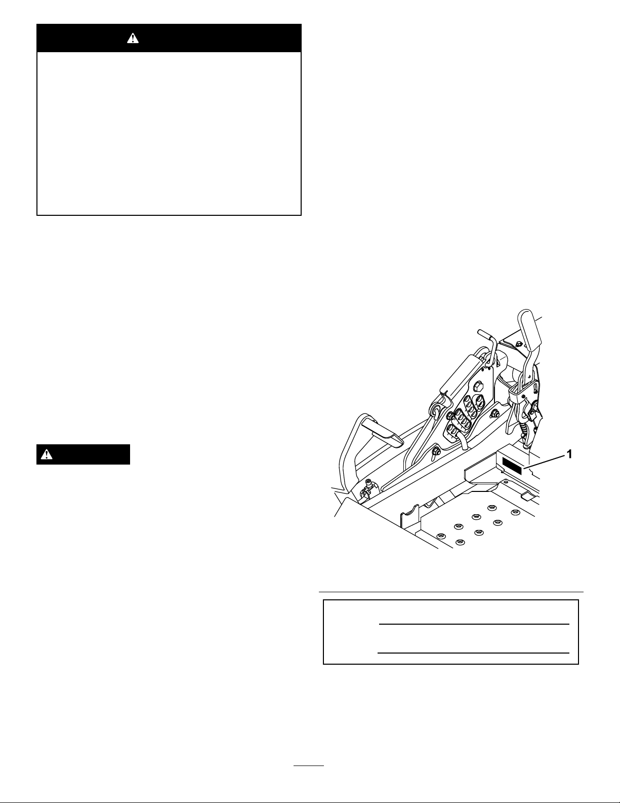
yourproductready .Figure1identiesthelocationofthe
modelandserialnumbersontheproduct.Writethenumbers
inthespaceprovided.
WARNING
Removingstandardoriginalequipmentpartsand
accessoriesmayalterthewarranty,traction,and
safetyofthemachine.FailuretouseoriginalToro
partscouldcauseseriousinjuryordeath.Making
unauthorizedchangestotheengine,fuelorventing
system,mayviolateEPAandCARBregulations.
Replaceallpartsincluding,butnotlimitedto,tires,
belts,blades,andfuelsystemcomponentswith
originalT oroparts.
Theenclosed
informationregardingtheUSEnvironmentalProtection
Agency(EPA)andtheCaliforniaEmissionControl
Regulationofemissionsystems,maintenance,and
warranty.Replacementsmaybeorderedthroughthe
enginemanufacturer.
Engine Owner's Man ual
issuppliedfor
Figure1
1.Modelandserialnumberlocation
ModelNo.
SerialNo.
Thismanualidentiespotentialhazardsandhassafety
messagesidentiedbythesafetyalertsymbol(Figure2),
whichsignalsahazardthatmaycauseseriousinjuryordeath
ifyoudonotfollowtherecommendedprecautions.
©2013—TheToro®Company
8111LyndaleAvenueSouth
Bloomington,MN55420
Contactusatwww.T oro.com.
2
PrintedintheUSA.
AllRightsReserved
Page 3

Figure2
1.Safetyalertsymbol
Thismanualuses2wordstohighlightinformation.
Importantcallsattentiontospecialmechanicalinformation
andNoteemphasizesgeneralinformationworthyofspecial
attention.
Contents
Introduction..................................................................2
Safety...........................................................................4
SafeOperatingPractices...........................................4
SlopeIndicator.......................................................6
SafetyandInstructionalDecals.................................7
ProductOverview.........................................................11
Controls...............................................................11
Specications........................................................12
Operation....................................................................13
AddingFuel...........................................................13
CheckingtheEngineOilLevel.................................14
BreakingInaNewMachine.....................................14
UsingtheRolloverProtectionSystem(ROPS)............14
ThinkSafetyFirst...................................................15
OperatingtheParkingBrake....................................15
OperatingtheMowerBladeControlSwitch
(PTO)...............................................................16
OperatingtheThrottle............................................16
OperatingtheIgnitionSwitch..................................16
UsingtheFuelShut-OffValve..................................17
StartingandStoppingtheEngine..............................17
TheSafetyInterlockSystem.....................................18
DrivingForwardorBackward..................................19
StoppingtheMachine.............................................20
AdjustingtheHeightofCut.....................................20
AdjustingtheAnti-scalpRollers................................21
AdjustingtheFlowBafeCamLocks........................22
PositioningtheFlowBafe......................................23
PositioningtheSeat................................................23
UsingtheDriveWheelReleaseValves.......................24
UsingtheSideDischarge.........................................24
LoadingMachines..................................................24
TransportingMachines............................................25
OperatingTips......................................................26
Maintenance.................................................................27
RecommendedMaintenanceSchedule(s)......................27
Lubrication...............................................................28
LubricatingtheMachine..........................................28
GreasingtheMower...............................................28
LubricatetheCasterWheelHubs..............................29
EngineMaintenance..................................................30
ServicingtheAirCleaner.........................................30
ServicingtheEngineOil..........................................31
ServicingtheSparkPlug..........................................34
ChecktheSparkArrester(ifequipped)......................35
FuelSystemMaintenance...........................................36
ServicingtheElectronicFuelInjection
System..............................................................36
ReplacingtheLowPressureFuelFilter......................36
ServicingtheHighPressureFuelFilter......................36
ServicingtheFuelTank...........................................36
ElectricalSystemMaintenance....................................37
ServicingtheBattery...............................................37
ServicingtheFuses.................................................38
DriveSystemMaintenance.........................................39
CheckingtheSeatBelt.............................................39
CheckingtheRolloverProtectionSystem(ROPS)
Knobs...............................................................39
AdjustingtheTracking............................................39
CheckingtheTirePressure......................................40
CheckingtheWheelLugNuts..................................40
CheckingtheWheelHubSlottedNut........................40
AdjustingtheCasterPivotBearing............................40
UsingtheClutchShim............................................41
CoolingSystemMaintenance......................................43
CleaningtheEngineScreenandEngineOil
Cooler...............................................................43
CleaningtheEngineCoolingFinsand
Shrouds.............................................................43
CheckandCleantheHydraulicUnits.........................43
BrakeMaintenance....................................................44
AdjustingtheParkingBrake.....................................44
BeltMaintenance......................................................45
InspectingtheBelts................................................45
ReplacingtheMowerBelt........................................45
ReplacingtheHydraulicPumpDriveBelt...................46
ControlsSystemMaintenance.....................................47
AdjustingtheControlHandlePosition......................47
AdjustingtheMotionControlLinkage......................48
AdjustingtheMotion-controlDamper......................49
AdjustingtheMotionControlNeutralLock
Pivot.................................................................49
HydraulicSystemMaintenance....................................50
ServicingtheHydraulicSystem.................................50
MowerDeckMaintenance...........................................52
LevelingtheMowerDeck........................................52
ServicingtheCuttingBlades.....................................53
RemovingtheMowerDeck.....................................55
ReplacingtheGrassDeector..................................56
Cleaning...................................................................57
CleaningUndertheMower......................................57
WasteDisposal.......................................................57
Storage........................................................................58
CleaningandStorage..............................................58
Troubleshooting...........................................................59
Schematics...................................................................62
3
Page 4

Safety
Improperuseormaintenancecanresultininjury.T oreduce
thepotentialforinjury,complywiththesesafetyinstructions
andalwayspayattentiontothesafetyalertsymbol,which
meansCAUTION,WARNING,orDANGER-“personal
safetyinstruction."Failuretocomplywiththeinstruction
mayresultinpersonalinjuryordeath.
Thisproductiscapableofamputatinghandsandfeetand
throwingobjects.Alwaysfollowallsafetyinstructionsto
avoidseriousinjuryordeath.
Thisproductisdesignedforcuttingandrecyclinggrassor,
whenequippedwithagrassbagger,forcatchingcutgrass.
Anyuseforpurposesotherthanthesecouldprovedangerous
touserandbystanders.
SafeOperatingPractices
ThefollowinginstructionsareadaptedfromANSIstandard
B71.4-2012.
Training
•ReadtheOperator'sManualandothertrainingmaterial.
Iftheoperator(s)ormechanic(s)cannotreadEnglishitis
theowner'sresponsibilitytoexplainthismaterialtothem.
•Becomefamiliarwiththesafeoperationoftheequipment,
operatorcontrols,andsafetysigns.
•Alloperatorsandmechanicsshouldbetrained.The
ownerisresponsiblefortrainingtheusers.
•Neverletchildrenoruntrainedpeopleoperateorservice
theequipment.Localregulationsmayrestricttheageof
theoperator.
•Theowner/usercanpreventandisresponsiblefor
accidentsorinjuriesoccurringtopeopleordamageto
property.
Preparation
•Evaluatetheterraintodeterminewhataccessoriesand
attachmentsareneededtoproperlyandsafelyperform
thejob.Onlyuseaccessoriesandattachmentsapproved
bythemanufacturer.
•Wearappropriateclothingincludinghardhat,safety
glassesandhearingprotection.Longhair,looseclothing
orjewelrymaygettangledinmovingparts.
•Inspecttheareawheretheequipmentistobeusedand
removeallobjectssuchasrocks,toysandwirewhichcan
bethrownbythemachine.
•Checkthatoperator'spresencecontrols,safetyswitches
andshieldsareattachedandfunctioningproperly.Donot
operateunlesstheyarefunctioningproperly.
Operation
•Lightningcancausesevereinjuryordeath.Iflightning
isseenorthunderisheardinthearea,donotoperate
themachine;seekshelter.
•Neverrunanengineinanenclosedarea.
•Onlyoperateingoodlight,keepingawayfromholesand
hiddenhazards.
•Besurealldrivesareinneutralandparkingbrakeis
engagedbeforestartingengine.Onlystartenginefrom
theoperator'sposition.
•Besureofyourfootingwhileusingthismachine,
especiallywhenbackingup.Walk,don'trun.Never
operateonwetgrass.Reducedfootingcouldcause
slipping.
•Slowdownanduseextracareonhillsides.Besureto
travelsidetosideonhillsides.Turfconditionscanaffect
themachine'sstability.Usecautionwhileoperatingnear
drop-offs.
•Slowdownandusecautionwhenmakingturnsandwhen
changingdirectionsonslopes.
•Neverraisedeckwiththebladesrunning.
•NeveroperatewiththePTOshield,orotherguardsnot
securelyinplace.Besureallinterlocksareattached,
adjustedproperly,andfunctioningproperly.
•Neveroperatewiththedischargedeectorraised,
removedoraltered,unlessusingagrasscatcher.
•Donotchangetheenginegovernorsettingoroverspeed
theengine.
•Stoponlevelground,disengagedrives,engageparking
brake(ifprovided),shutoffenginebeforeleavingthe
operator'spositionforanyreasonincludingemptyingthe
catchersoruncloggingthechute.
•Stopequipmentandinspectbladesafterstrikingobjects
orifanabnormalvibrationoccurs.Makenecessary
repairsbeforeresumingoperations.
•Keephandsandfeetawayfromthecuttingunit.
•Lookbehindanddownbeforebackinguptobesureof
aclearpath.
•Keeppetsandbystandersaway.
•Slowdownandusecautionwhenmakingturnsand
crossingroadsandsidewalks.Stopbladesifnotmowing.
•Beawareofthemowerdischargedirectionanddonot
pointitatanyone.
•Donotoperatethemowerundertheinuenceofalcohol
ordrugs.
•Usecarewhenloadingorunloadingthemachineinto
orfromatrailerortruck.
•Usecarewhenapproachingblindcorners,shrubs,trees,
orotherobjectsthatmayobscurevision.
•Lightningcancausesevereinjuryordeath.Iflightning
isseenorthunderisheardinthearea,donotoperate
themachine;seekshelter.
4
Page 5

RolloverProtectionSystem(ROPS)UseandMaintenance
•TheROPSisanintegralandeffectivesafetydevice.Keep
afoldingROPSintheraisedandlockedpositionanduse
theseatbeltwhenoperatingthemachine.
•LowerafoldingROPStemporarilyonlywhenabsolutely
necessary.Donotweartheseatbeltwhenfoldeddown.
•Beawarethereisnorolloverprotectionwhenafolded
ROPSisinthedownposition.
•Becertainthattheseatbeltcanbereleasedquicklyin
theeventofanemergency.
•Iffuelisspilledonclothing,changeclothingimmediately.
•Neveroverllfueltank.Replacefuelcapandtighten
securely.
Maintenanceandstorage
•Disengagedrives,setparkingbrake,stopengineand
removekeyordisconnectsparkplugwire.W aitforall
movementtostopbeforeadjusting,cleaningorrepairing.
•Cleangrassanddebrisfromcuttingunit,drives,mufers,
andenginetohelppreventres.Cleanupoilorfuel
spillage.
•Checktheareatobemowedandneverfolddowna
foldingROPSinareaswherethereareslopes,dropoffs
orwater.
•Checkcarefullyforoverheadclearances(i.e.branches,
doorways,electricalwires)beforedrivingunderany
objectsanddonotcontactthem.
•KeeptheROPSinsafeoperatingconditionby
periodicallythoroughlyinspectingfordamageand
keepingallmountingfastenerstight.
•ReplaceadamagedROPS.Donotrepairorrevise.
•DonotremovetheROPS.
•AnyalterationstoaROPSmustbeapprovedbythe
manufacturer.
Safehandlingoffuels
•Toavoidpersonalinjuryorpropertydamage,use
extremecareinhandlinggasoline.Gasolineisextremely
ammableandthevaporsareexplosive.
•Extinguishallcigarettes,cigars,pipes,andothersources
ofignition.
•Useonlyanapprovedfuelcontainer.
•Neverremovefuelcaporaddfuelwiththeengine
running.
•Allowenginetocoolbeforerefueling.
•Letenginecoolbeforestoringanddonotstorenear
ame.
•Shutofffuelwhilestoringortransporting.Donotstore
fuelnearamesordrainindoors.
•Parkmachineonlevelground.Setparkingbrake.Never
allowuntrainedpersonneltoservicemachine.
•Usejackstandstosupportcomponentswhenrequired.
•Carefullyreleasepressurefromcomponentswithstored
energy.
•Disconnectthebatteryorremovesparkplugwirebefore
makinganyrepairs.Disconnectthenegativeterminalrst
andthepositivelast.Reconnectthepositiverstand
negativelast.
•Usecarewhencheckingblades.Wraptheblade(s)or
weargloves,andusecautionwhenservicingthem.Only
replaceblades.Neverstraightenorweldthem.
•Keephandsandfeetawayfrommovingparts.Ifpossible,
donotmakeadjustmentswiththeenginerunning.
•Keepallpartsingoodworkingconditionandallhardware
tightened.Replaceallwornordamageddecals.
Hauling
•Usecarewhenloadingorunloadingthemachineintoa
trailerortruck.
•Neverrefuelthemachineindoors.
•Neverstorethemachineorfuelcontainerwherethereis
anopename,spark,orpilotlightsuchasonawater
heateroronotherappliances.
•Neverllcontainersinsideavehicleoronatruckor
trailerbedwithaplasticliner.Alwaysplacecontainerson
thegroundawayfromyourvehiclebeforelling.
•Removeequipmentfromthetruckortrailerandrefuelit
ontheground.Ifthisisnotpossible,thenrefuelsuch
equipmentwithaportablecontainer,ratherthanfroma
fueldispensernozzle.
•Keepthenozzleincontactwiththerimofthefueltank
orcontaineropeningatalltimesuntilfuelingiscomplete.
Donotuseanozzlelockopendevice.
•Usefullwidthrampsforloadingmachineintotraileror
truck.
•Tiethemachinedownsecurelyusingstraps,chains,cable,
orropes.Bothfrontandrearstrapsshouldbedirected
downandoutwardfromthemachine.
5
Page 6
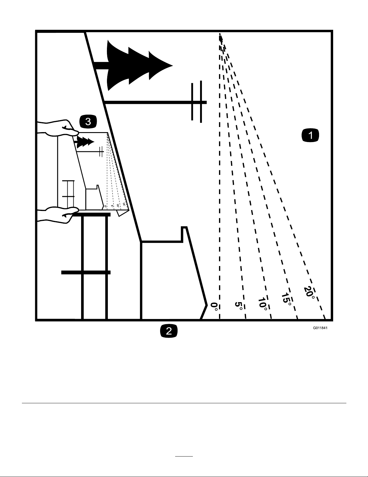
SlopeIndicator
G011841
Figure3
Thispagemaybecopiedforpersonaluse.
1.Themaximumslopeyoucansafelyoperatethemachineonis15degrees.Usetheslopecharttodeterminethedegreeofslope
ofhillsbeforeoperating.Donotoperatethismachineonaslopegreaterthan15degrees.Foldalongtheappropriateline
tomatchtherecommendedslope.
2.Alignthisedgewithaverticalsurface,atree,building,fencepole,etc.
3.Exampleofhowtocompareslopewithfoldededge.
6
Page 7

SafetyandInstructionalDecals
Safetydecalsandinstructionsareeasilyvisibletotheoperatorandarelocatednearanyareaofpotential
danger.Replaceanydecalthatisdamagedorlost.
1-403005
68-8340
98-5954
103-2076
54-9220
58-6520
1.Grease
105-7798
116-2643
66-1340
7
Page 8
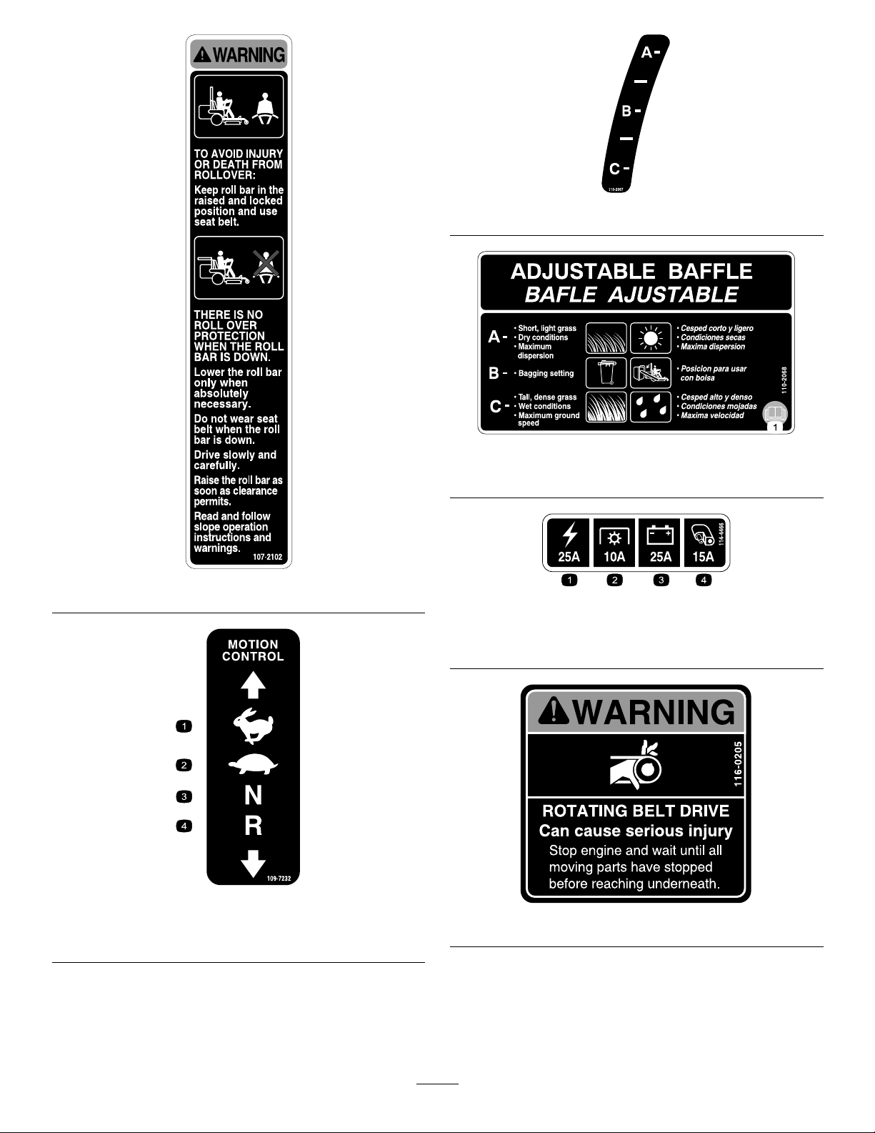
110-2067
110-2068
1.ReadtheOperator'sManual.
107-2102
114-4466
109-7232
1.Fast3.Neutral
2.Slow
1.Main,25A
2.PTO,10A
3.Charge,25A
4.Auxiliary,15A
116-0205
4.Reverse
8
Page 9
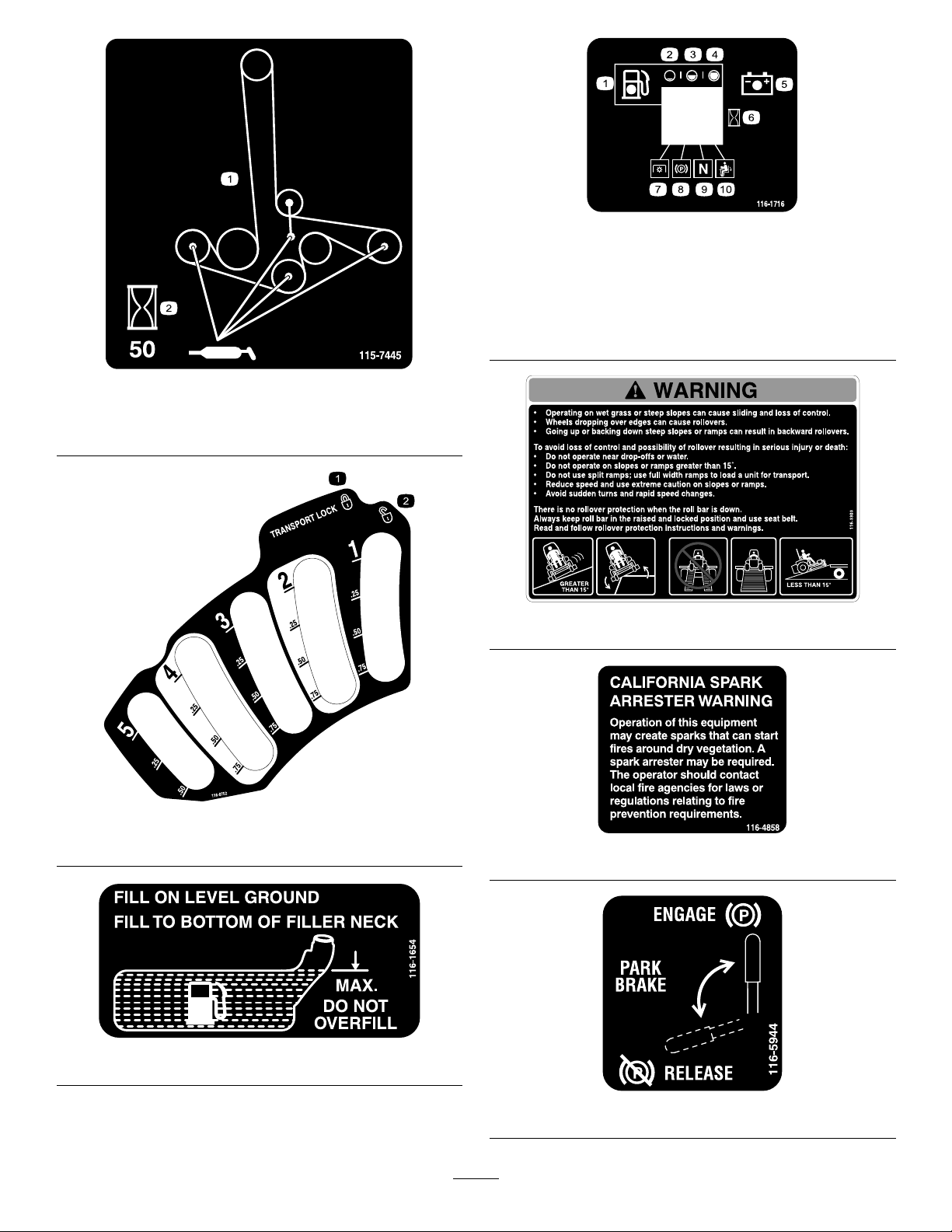
1.Greasepulleysandspindles
2.Maintenanceinterval—50hours
116-1716
1.Fuel6.Hourmeter
2.Empty
3.Half
4.Full9.Neutral
5.Battery
7.PTO
8.Parkingbrake
10.Operatorpresenceswitch
115-7445
116-3303
116-0752
1.Latch2.Unlatch
116-1654
116-4858
116-5944
9
Page 10
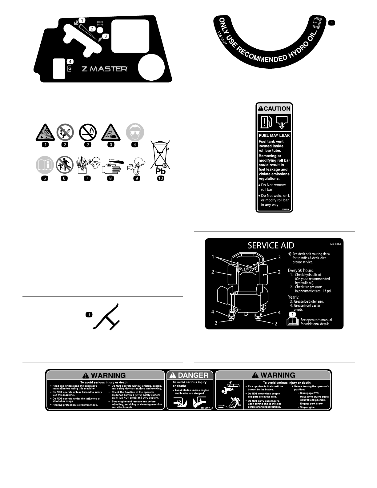
116-0157
121–7586
1.Fast
2.Variablespeedcontrol
3.Slow
4.Powertake-off(PTO)
BatterySymbols
Someorallofthesesymbolsareonyourbattery
1.Explosionhazard
2.Nore,opename,or
smoking.
3.Causticliquid/chemical
burnhazard
4.Weareyeprotection9.Flusheyesimmediately
5.ReadtheOperator's
Manual.
6.Keepbystandersasafe
7.Weareyeprotection;
8.Batteryacidcancause
10.Containslead;donot
1.Onlyuserecommendedhydrooil
distancefromthebattery .
116-0090
explosivegasescan
causeblindnessandother
injuries
blindnessorsevereburns.
withwaterandgetmedical
helpfast.
discard.
Manufacturer'sMark
1.Indicatesthebladeisidentiedasapartfromtheoriginal
machinemanufacturer.
125–9382
1.ReadtheOperator’sManualformoreinformationon
servicingthemachine.
109-7069
10
Page 11
ProductOverview
G014939
g0131 12
1
2
3
4
5
6
25
25
10
15
C
H
ECK
ENG
IN
E
HourMeter
Thehourmeterrecordsthenumberofhourstheenginehas
operated.Itoperateswhentheengineisrunning.Usethese
timesforschedulingregularmaintenance(Figure5).
FuelGauge
Thefuelgaugeislocatedwiththehourmeterandthebars
lightupwhentheignitionswitchison(Figure6).
Theindicatorlightappearswhenthefuellevelislow
(approximatelyonegallonremaininginthefueltank).
SafetyInterlockIndicators
Therearesymbolsonthehourmeterandtheindicatewitha
blacktrianglethattheinterlockcomponentisinthecorrect
position(
Figure5).
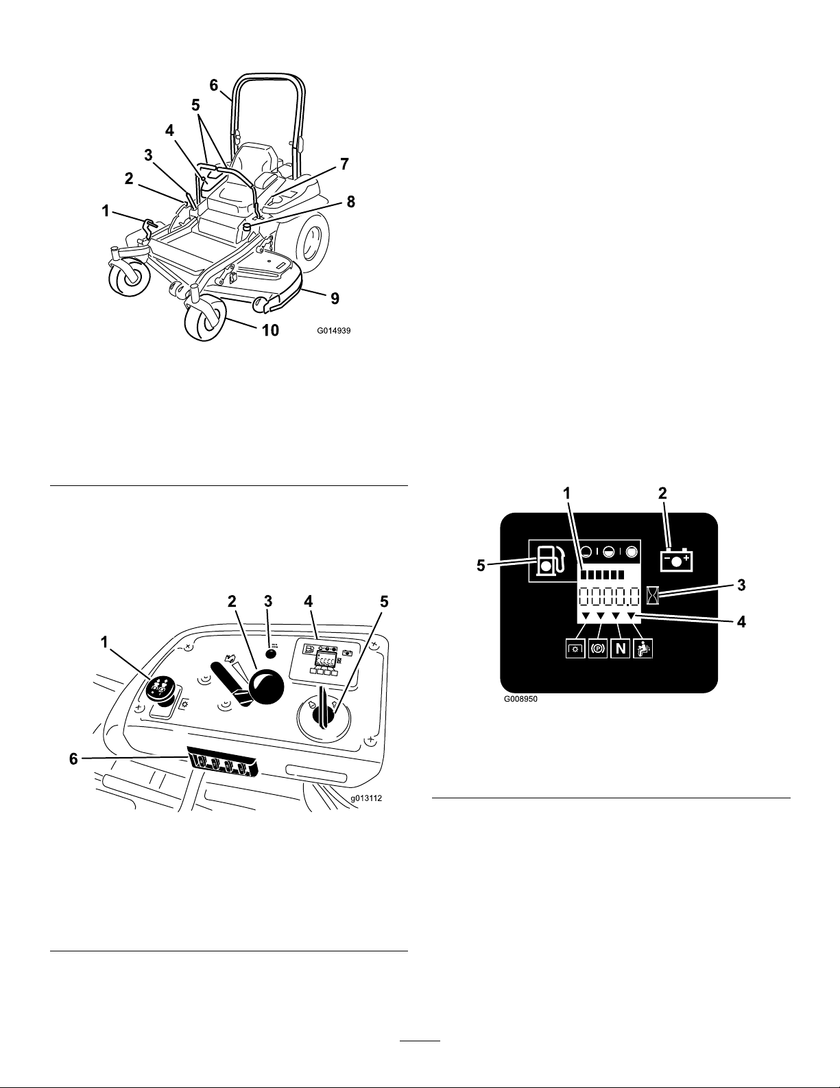
Figure4
1.Height-of-cutdecklift
pedal
2.Transportlock
3.Parkingbrakelever8.Fuelcap
4.Controls
5.Motioncontrollevers
6.Rollbar
7.Seatbelt
9.Mowerdeck
10.Casterwheel
Controls
Becomefamiliarwithallthecontrolsbeforeyoustartthe
engineandoperatethemachine(Figure4andFigure5).
BatteryIndicatorLight
IftheignitionkeyisturnedtotheOnpositionforafew
seconds,thebatteryvoltagewillbedisplayedinthearea
wherethehoursarenormallydisplayed.
Thebatterylightturnsonwhentheignitionisturnedonand
whenthechargeisbelowthecorrectoperatinglevel(
6).
Figure6
1.Fuelgauge(bars)4.Safetyinterlocksymbols
2.Batterylight
3.Hourmeter
5.Lowfuelindicatorlight
Figure
Figure5
1.PTOSwitch4.Hourmeter/Safety
2.Throttlecontrol5.Ignitionswitch
3.Malfunctionindicatorlight
(MIL)
interlockdisplay/Fuel
gauge
6.Fuses
ThrottleControl
ThethrottlecontrolisvariablebetweentheFastandSlow
positions.
BladeControlSwitch(PTO)
Thebladecontrolswitch(PTO)isusedtoengagetheelectric
clutchanddrivethemowerblades.Pulltheswitchupto
engagethebladesandrelease.Todisengagetheblades,push
thebladecontrolswitch(PTO)downormoveamotion
controlleverintotheneutrallockposition.
11
Page 12

IgnitionSwitch
Length:
Thisswitchisusedtostartthemowerengineandhas3
positions:Start,Run,andOff.
MotionControlLevers
Themotioncontrolleversareusedtodrivethemachine
forward,reverse,andturneitherdirection.
NeutralLockPosition
Theneutrallockpositionisusedwiththesafetyinterlock
systemtoengageandtodetermineneutralposition.
FuelShut-offValve
Closethefuelshut-offvalve(undertheseat)when
transportingorstoringthemower.
ElectronicControlUnitMalfunction
IndicatorLight
Theelectroniccontrolunit(ECU)continuouslymonitorsthe
operationoftheEFIsystem.
60inchDeck
RollBar-Up
RollBar-Down
211.1cm(83.1inches)
215.4cm(84.8inches)
Height:
RollBar-UpRollBar-Down
179.1cm(70.5inches)118.9cm(46.8inches)
Weight:
ModelWeight
74958
532kg(1172lbs)
Ifaproblemorfaultwithinthesystemisdetected,the
malfunctionindicatorlight(MIL)isilluminated.
TheMIListheredlightlocatedintherightconsolepanel.
OncetheMILilluminates,initialtroubleshooting
checksshouldbemade.RefertotheMILsectionunder
Toubleshooting.
Ifthesechecksdonotcorrecttheproblem,furtherdiagnosis
andservicingbyanAuthorizedServiceDealerisnecessary.
Attachments/Accessories
AselectionofToroapprovedattachmentsandaccessoriesis
availableforusewiththemachinetoenhanceandexpand
itscapabilities.ContactyourAuthorizedServiceDealeror
Distributororgotowww .T oro.comforalistofallapproved
attachmentsandaccessories.
Specications
Note:Specicationsanddesignaresubjecttochange
withoutnotice.
Width:
60inchDeck
WithoutDeck
DeectorUp156.8cm(61.7inches)
DeectorDown192.2cm(75.7inches)
134.6cm(53.0inches)
12
Page 13

Operation
Note:Determinetheleftandrightsidesofthemachine
fromthenormaloperatingposition.
AddingFuel
•Forbestresults,useonlyclean,fresh(lessthan30days
old),unleadedgasolinewithanoctaneratingof87or
higher((R+M)/2ratingmethod).
•Ethanol:Gasolinewithupto10%ethanol(gasohol)
or15%MTBE(methyltertiarybutylether)byvolume
isacceptable.EthanolandMTBEarenotthesame.
Gasolinewith15%ethanol(E15)byvolumeisnot
approvedforuse.Neverusegasolinethatcontains
morethan10%ethanolbyvolume,suchasE15
(contains15%ethanol),E20(contains20%ethanol),or
E85(containsupto85%ethanol).Usingunapproved
gasolinemaycauseperformanceproblemsand/orengine
damagewhichmaynotbecoveredunderwarranty.
•Donotusegasolinecontainingmethanol.
•Donotstorefueleitherinthefueltankorfuelcontainers
overthewinterunlessafuelstabilizerisused.
•Donotaddoiltogasoline.
DANGER
Incertainconditionsduringfueling,static
electricitycanbereleasedcausingasparkwhich
canignitethegasolinevapors.Areorexplosion
fromgasolinecanburnyouandothersandcan
damageproperty.
•Alwaysplacegasolinecontainersontheground
awayfromyourvehiclebeforelling.
•Donotllgasolinecontainersinsideavehicleor
onatruckortrailerbedbecauseinteriorcarpets
orplastictruckbedlinersmayinsulatethe
containerandslowthelossofanystaticcharge.
•Whenpractical,removegas-poweredequipment
fromthetruckortrailerandrefueltheequipment
withitswheelsontheground.
•Ifthisisnotpossible,thenrefuelsuch
equipmentonatruckortrailerfromaportable
container,ratherthanfromagasolinedispenser
nozzle.
•Ifagasolinedispensernozzlemustbeused,
keepthenozzleincontactwiththerimofthe
fueltankorcontaineropeningatalltimesuntil
fuelingiscomplete.
DANGER
Incertainconditions,gasolineisextremely
ammableandhighlyexplosive.Areorexplosion
fromgasolinecanburnyouandothersandcan
damageproperty.
•Fillthefueltankoutdoors,inanopenarea,
whentheengineiscold.Wipeupanygasoline
thatspills.
•Neverllthefueltankinsideanenclosedtrailer.
•Donotllthefueltankcompletelyfull.Add
gasolinetothefueltankuntilthelevelis6to13
mm(1/4to1/2inch)belowthebottomofthe
llerneck.Thisemptyspaceinthetankallows
gasolinetoexpand.
•Neversmokewhenhandlinggasoline,andstay
awayfromanopenameorwheregasoline
fumesmaybeignitedbyaspark.
•Storegasolineinanapprovedcontainerand
keepitoutofthereachofchildren.Neverbuy
morethana30-daysupplyofgasoline.
•Donotoperatewithoutentireexhaustsystemin
placeandinproperworkingcondition.
WARNING
Gasolineisharmfulorfatalifswallowed.Long-term
exposuretovaporscancauseseriousinjuryand
illness.
•Avoidprolongedbreathingofvapors.
•Keepfaceawayfromnozzleandgastankor
conditionerbottleopening.
•Avoidcontactwithskin;washoffspillagewith
soapandwater.
UsingStabilizer/Conditioner
Useafuelstabilizer/conditionerinthemachinetoprovide
thefollowingbenets:
•Keepsgasolinefreshduringstorageof90daysorless.
Forlongerstorageitisrecommendedthatthefueltank
bedrained.
•Cleanstheenginewhileitruns
•Eliminatesgum-likevarnishbuildupinthefuelsystem,
whichcauseshardstarting
Important:Donotusefueladditivescontaining
methanolorethanol.
Addthecorrectamountofgasstabilizer/conditionerto
thegas.
Note:Afuelstabilizer/conditionerismosteffective
whenmixedwithfreshgasoline.Tominimizethechance
13
Page 14

ofvarnishdepositsinthefuelsystem,usefuelstabilizer
atalltimes.
Important:Lowertherollbaronlywhenabsolutely
necessary.
FillingtheFuelTank
1.Shuttheengineoffandsettheparkingbrake.
2.Cleanaroundthefueltankcapandremovethecap.
Addunleadedregulargasolinetothefueltank,untilthe
levelis6to13mm(1/4to1/2inch)belowthebottom
ofthellerneck.Thisspaceinthetankallowsthe
gasolinetoexpand.Donotllthefueltankcompletely
full.
3.Installthefueltankcapsecurely.Wipeupanygasoline
thatmayhavespilled.
CheckingtheEngineOilLevel
Beforeyoustarttheengineandusethemachine,checktheoil
levelintheenginecrankcase;refertoCheckingtheEngine
OilLevel(page31).
BreakingInaNewMachine
Newenginestaketimetodevelopfullpower.Mowerdecks
anddrivesystemshavehigherfrictionwhennew,placing
additionalloadontheengine.Allow40to50hoursof
break-intimefornewmachinestodevelopfullpowerand
bestperformance.
Important:Ensurethattheseatissecuredtothe
machine.
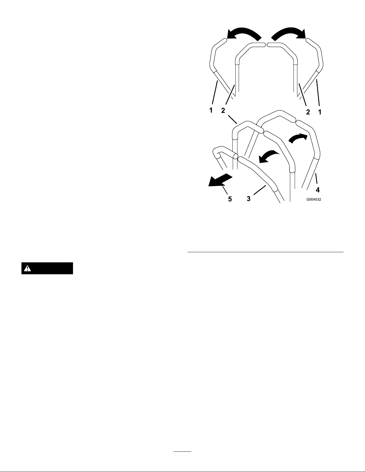
1.Tolowertherollbar,applyforwardpressuretothe
upperpartoftherollbar.
2.Pullbothknobsoutandrotatethem90°sothatthey
arenotengaged(Figure7).
3.Lowertherollbartothedownposition(Figure7).
UsingtheRolloverProtection System(ROPS)
WARNING
Toavoidinjuryordeathfromrollover:keeptheroll
barinthefullyraisedlockedpositionandusethe
seatbelt.
Ensurethattheseatissecuredtothemachine.
WARNING
Thereisnorolloverprotectionwhentherollbaris
inthedownposition.
•Lowertherollbaronlywhenabsolutely
necessary.
•Donotweartheseatbeltwhentherollbaris
inthedownposition.
•Driveslowlyandcarefully.
•Raisetherollbarassoonasclearancepermits.
•Checkcarefullyforoverheadclearances(i.e.
branches,doorways,electricalwires)before
drivingunderanyobjectsanddonotcontact
them.
Figure7
1.ROPSknob
2.PullROPSknoboutand
rotate90degrees
4.Toraisetherollbar,raisetherollbartotheoperate
position,rotatetheknobssotheymovepartiallyinto
thegrooves(Figure7).
5.Raisetherollbartothefulluprightpositionwhile
pushingontheupperrollbarandthepinswillsnap
intopositionwhentheholesalignwiththepins(Figure
7).Pushontherollbarandensurethatbothpinsare
engaged.
3.Rollbarintheupright
position
4.Rollbarinthefolded
position
14
Page 15
Important:Alwaysusetheseatbeltwiththeroll
G009027
1
2
G016994
1
2
barinthefullyraisedposition.
ThinkSafetyFirst
Pleasereadallsafetyinstructionsandsymbolsinthesafety
section.Knowingthisinformationcouldhelpyouor
bystandersavoidinjury.
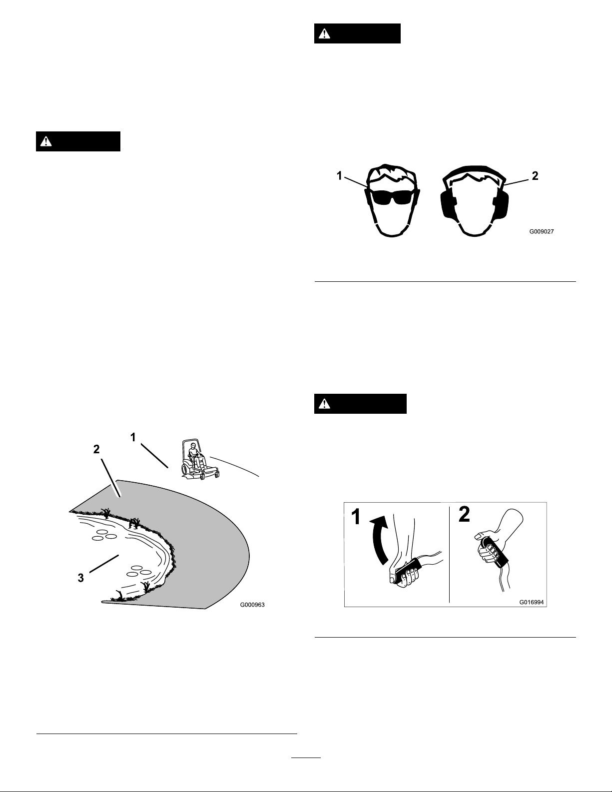
CAUTION
Thismachineproducessoundlevelsinexcessof
85dBAattheoperatorsearandcancausehearing
lossthroughextendedperiodsofexposure.
Wearhearingprotectionwhenoperatingthis
machine.
DANGER
Operatingonwetgrassorsteepslopescancause
slidingandlossofcontrol.
Wheelsdroppingoveredgescancauserollovers,
whichmayresultinseriousinjury,deathor
drowning.
Thereisnorolloverprotectionwhentherollbaris
down.
Alwayskeeptherollbarinthefullyraisedand
lockedpositionandusetheseatbelt.
Readandfollowtherolloverprotectioninstructions
andwarnings.
Toavoidlossofcontrolandpossibilityofrollover:
•Donotoperateneardrop-offsornearwater.
•Donotoperateonslopesgreaterthan15degrees.
•Reducespeedanduseextremecautionon
slopes.
•Avoidsuddenturnsorrapidspeedchanges.
Theuseofprotectiveequipmentforeyes,ears,feet,andhead
isrecommended.
Figure9
1.Wearsafetyglasses
2.Wearhearingprotection
OperatingtheParkingBrake
Alwayssettheparkingbrakewhenyoustopthemachineor
leaveitunattended.
SettingtheParkingBrake
WARNING
Parkingbrakemaynotholdmachineparkedona
slopeandcouldcausepersonalinjuryorproperty
damage.
Donotparkonslopesunlesswheelsarechocked
orblocked
Figure8
1.SafeZone-usethe
ZMasterhereonslopes
lessthan15degreesor
atareas.
2.DangerZone-useawalk
behindmowerand/ora
handtrimmeronslopes
greaterthan15degrees,
neardrop-offsandwater.
3.Water
Figure10
15
Page 16
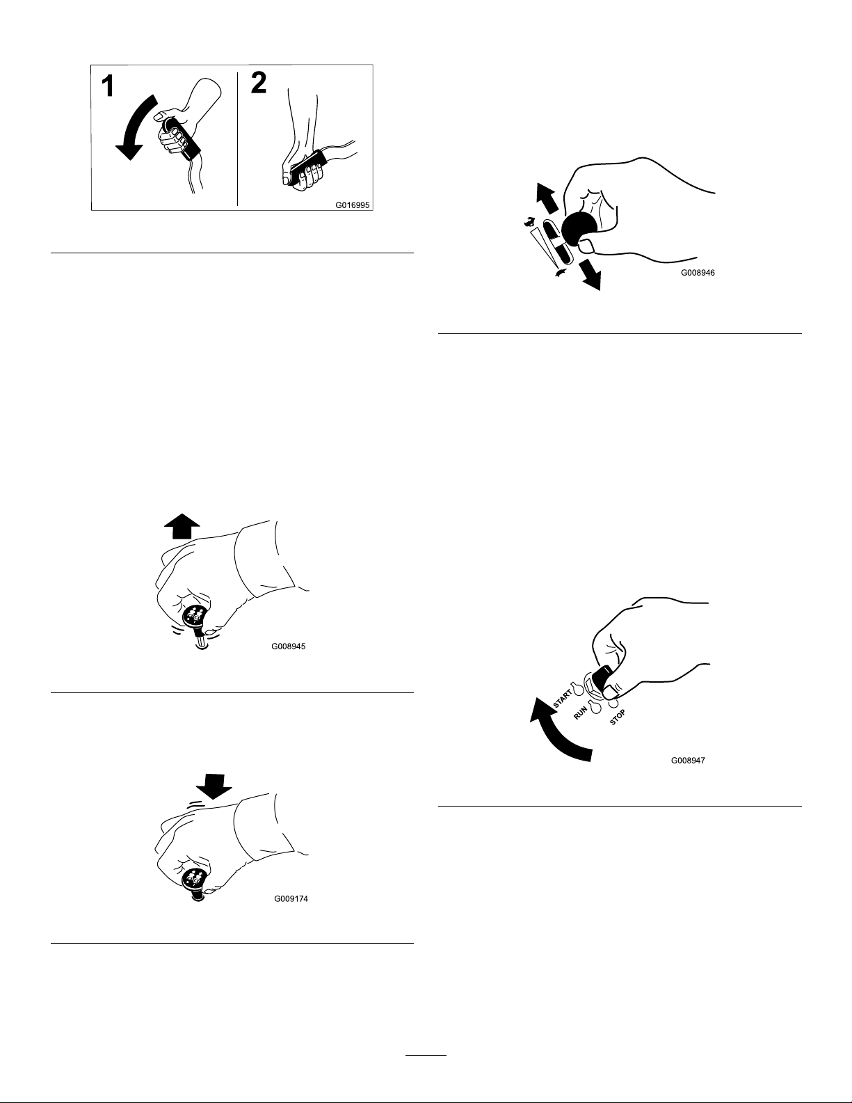
ReleasingtheParkingBrake
G016995
1
2
G008945
G009174
G008946
START
RUN
STOP
G008947
OperatingtheThrottle
ThethrottlecontrolcanbemovedbetweentheFastand
Slowpositions(Figure14).
Alwaysusethefastpositionwhenturningonthemowerdeck
withthebladecontrolswitch(PTO).
Figure11
OperatingtheMowerBlade ControlSwitch(PTO)
Thebladecontrolswitch(PTO)startsandstopsthemower
bladesandanypoweredattachments.
EngagingtheBladeControlSwitch
(PTO)
Note:Engagingthebladecontrolswitch(PTO)withthe
throttlepositionathalforlesswillcauseexcessivewearto
thedrivebelts.
Figure12
Figure14
OperatingtheIgnitionSwitch
1.TurntheignitionkeytotheStartposition(Figure15).
Whentheenginesstarts,releasethekey .
Important:Donotengagestarterformorethan5
secondsatatime.Iftheenginefailstostartallow
a15secondcool-downperiodbetweenattempts.
Failuretofollowtheseinstructionscanburnout
thestartermotor.
Note:Additionalstartingcyclesmayberequired
whenstartingtheengineforthersttimeafterthefuel
systemhasbeenwithoutfuelcompletely.
DisengagingtheBladeControlSwitch
(PTO)
Figure15
2.Turntheignitionkeytostoptostoptheengine.
Figure13
16
Page 17
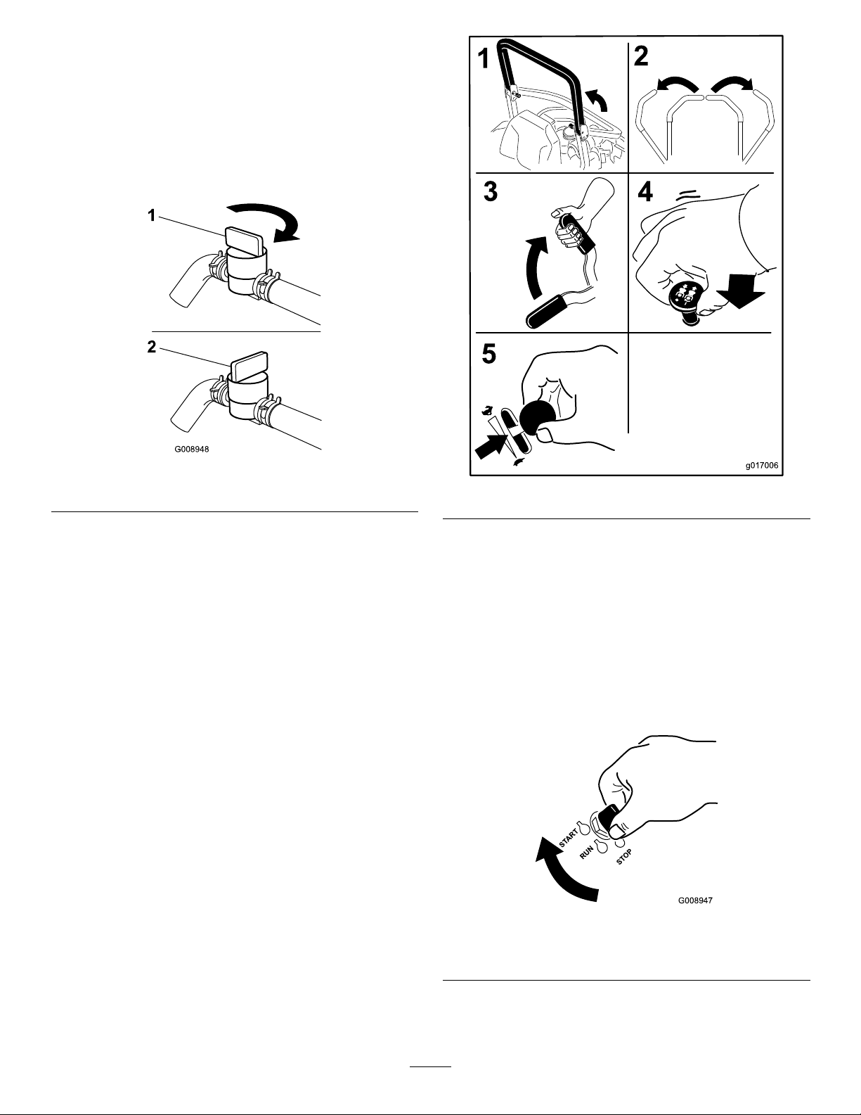
UsingtheFuelShut-OffValve
G008948
1
2
g017006
START
RUN
STOP
G008947
Thefuelshut-offvalveislocatedundertheseat.Movethe
seatforwardtoaccessit.
Closethefuelshut-offvalvefortransport,maintenance,and
storage.
Ensurethefuelshut-offvalveisopenwhenstartingthe
engine.
Figure16
1.On2.Off
StartingandStoppingthe Engine
StartingtheEngine
1.RaisetheROPSupandlockintoplace,sitontheseat
andfastentheseatbelt.
2.Movethemotioncontrolstoneutrallockedposition.
3.Settheparkingbrake;refertoSettingtheParking
Brake(page15).
4.Movethebladecontrolswitch(PTO)totheoff
position(Figure17).
5.Movethethrottlelevermidwaybetweentheslowand
fastpositions.
Figure17
6.TurntheignitionkeytotheStartposition(Figure15).
Whentheenginesstarts,releasethekey .
Important:Donotengagestarterformorethan5
secondsatatime.Iftheenginefailstostartallow
a15secondcool-downperiodbetweenattempts.
Failuretofollowtheseinstructionscanburnout
thestartermotor.
Note:Additionalstartingcyclesmayberequired
whenstartingtheengineforthersttimeafterthefuel
systemhasbeenwithoutfuelcompletely.
Figure18
1.Off3.Start
2.Run
17
Page 18
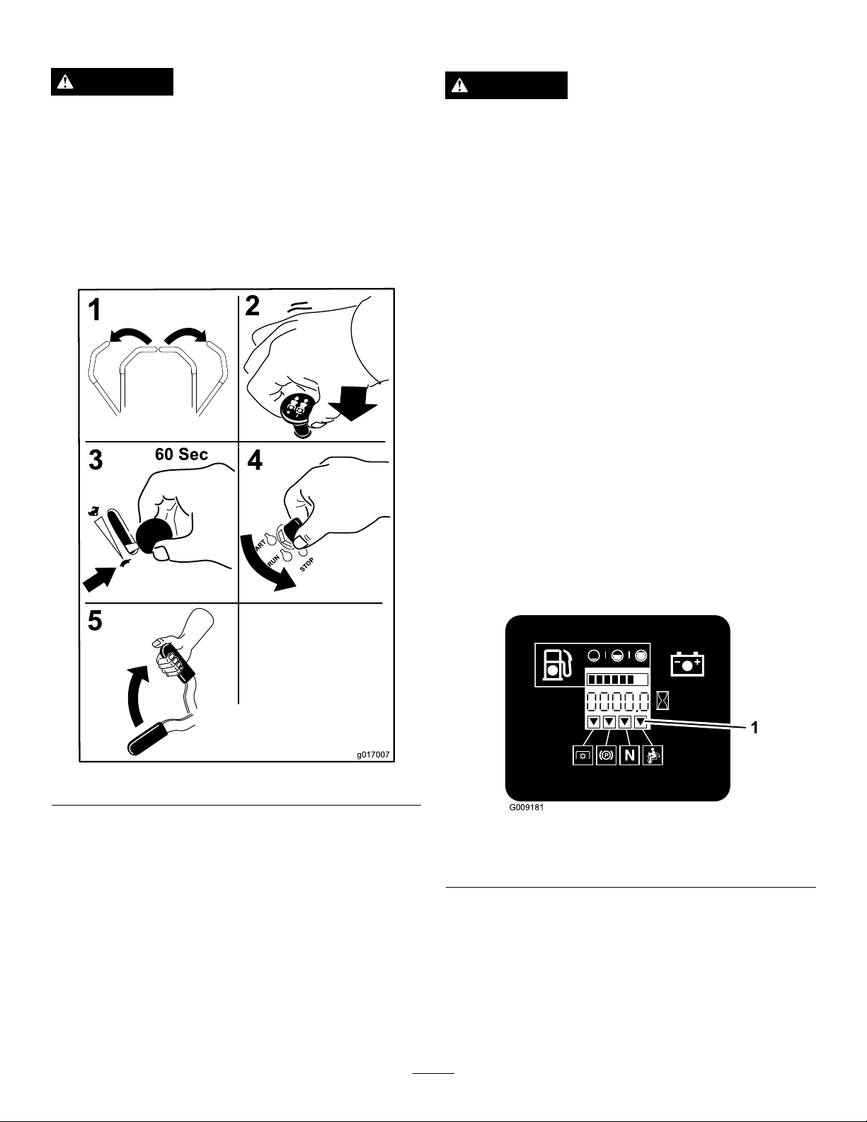
StoppingtheEngine
g017007
G009181
1
TheSafetyInterlockSystem
CAUTION
Childrenorbystandersmaybeinjuredifthey
moveorattempttooperatethemachinewhileitis
unattended.
Alwaysremovetheignitionkeyandsettheparking
brakewhenleavingthemachineunattended,even
ifjustforafewminutes.
Lettheengineidleatslowthrottle(turtle)for60seconds
beforeturningtheignitionswitchoff.
CAUTION
Ifsafetyinterlockswitchesaredisconnectedor
damagedthemachinecouldoperateunexpectedly
causingpersonalinjury.
•Donottamperwiththeinterlockswitches.
•Checktheoperationoftheinterlockswitches
dailyandreplaceanydamagedswitchesbefore
operatingthemachine.
UnderstandingtheSafetyInterlock
System
Thesafetyinterlocksystemisdesignedtopreventtheengine
fromstartingunless:
•Theparkingbrakeisengaged.
•Thebladecontrolswitch(PTO)isdisengaged.
•Themotioncontrolleversareintheneutrallocked
position
Thesafetyinterlocksystemalsoisdesignedtostopthe
enginewhenthetractioncontrolsaremovedfromthelocked
positionwiththeparkingbrakeengagedorifyourisefrom
theseatwhenthePTOisengaged.
Figure19
Important:Makesurethatthefuelshutoffvalveis
closedbeforetransportingorstoringthemachine,as
fuelleakagemayoccur.Settheparkingbrakebefore
transporting.Makesuretoremovethekeyasthefuel
pumpmayrunandcausethebatterytolosecharge.
Thehourmeterhassymbolstonotifytheuserwhenthe
interlockcomponentisinthecorrectposition.Whenthe
componentisinthecorrectposition,atrianglewilllightup
inthecorrespondingsquare.
Figure20
1.Triangleslightupwhentheinterlockcomponentsareinthe
correctposition
TestingtheSafetyInterlockSystem
ServiceInterval:Beforeeachuseordaily
Testthesafetyinterlocksystembeforeyouusethemachine
eachtime.Ifthesafetysystemdoesnotoperateasdescribed
below,haveanAuthorizedServiceDealerrepairthesafety
systemimmediately.
18
Page 19
1.Sittingontheseat,engagetheparkingbrakeandmove
thebladecontrolswitch(PTO)toon.Trystartingthe
engine;theengineshouldnotcrank.
2.Sittingontheseat,engagetheparkingbrakeandmove
thebladecontrolswitch(PTO)tooff.Moveeither
motioncontrollever(outofneutrallockedposition).
Trystartingtheengine;theengineshouldnotcrank.
Repeatforothercontrollever.
3.Sittingontheseat,engagetheparkingbrake,movethe
bladecontrolswitch(PTO)tooffandmovethemotion
controlleverstoneutrallockposition.Nowstartthe
engine.Whiletheengineisrunning,releasetheparking
brake,engagethebladecontrolswitch(PTO)andrise
slightlyfromtheseat;theengineshouldstop.
4.Sittingontheseat,engagetheparkingbrake,movethe
bladecontrolswitch(PTO)tooffandmovethemotion
controlleverstoneutrallockposition.Nowstartthe
engine.Whiletheengineisrunning,centereither
motioncontrolandmove(forwardorreverse);the
engineshouldstop.Repeatforothermotioncontrol.
5.Sittingontheseat,disengagetheparkingbrake,move
thebladecontrolswitch(PTO)tooffandmovethe
motioncontrolleverstoneutrallockposition.Try
startingtheengine;theengineshouldnotcrank.
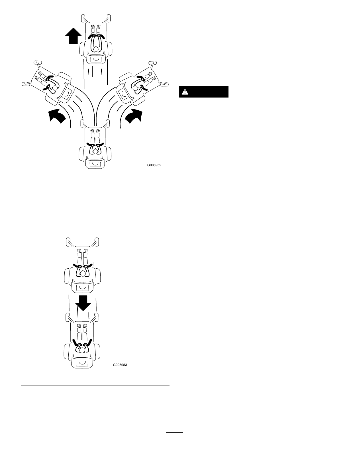
UsingtheMotionControlLevers
DrivingForwardorBackward
Thethrottlecontrolregulatestheenginespeedasmeasured
inrpm(revolutionsperminute).Placethethrottlecontrolin
thefastpositionforbestperformance.Alwaysoperateinthe
fullthrottlepositionwhenmowing.
CAUTION
Machinecanspinveryrapidly.Operatormaylose
controlofmachineandcausepersonalinjuryor
damagetomachine.
•Usecautionwhenmakingturns.
•Slowthemachinedownbeforemakingsharp
turns.
Figure21
1.Motioncontrol
lever-neutrallockposition
2.Center,unlockedposition5.Frontofmachine
3.Forward
4.Backward
DrivingForward
Note:Theenginewillkillifthetractioncontrolleversare
movedwiththeparkingbrakeengaged.
Tostop,pullthemotioncontrolleverstotheneutralposition.
1.Releasetheparkingbrake;refertoReleasingthe
ParkingBrake(page16).
2.Movetheleverstothecenter,unlockedposition.
3.Togoforward,slowlypushthemotioncontrollevers
forward(Figure22).
19
Page 20
G008952
Figure22
G008953
StoppingtheMachine
Tostopthemachine,movethetractioncontrolleversto
neutralandmovetolockedposition,disengagethepower
takeoff(bladecontrolswitch(PTO),andturntheignition
keytotheoffposition.
Settheparkingbrakewhenyouleavethemachine;referto
SettingtheParkingBrake(page15).Removethekeyfrom
theignitionswitch.
CAUTION
Childrenorbystandersmaybeinjuredifthey
moveorattempttooperatethemachinewhileitis
unattended.
Alwaysremovetheignitionkeyandsettheparking
brakewhenleavingthemachineunattended,even
ifjustforafewminutes.
AdjustingtheHeightofCut
UsingtheTransportLock
DrivingBackward
1.Movetheleverstothecenter,unlockedposition.
2.Togobackward,slowlypullthemotioncontrollevers
rearward(
Figure23).
Thetransportlockhas2positionsandisusedwiththedeck
liftpedal.Thereisalockpositionandaunlockpositionfor
thetransportposition.Thetransportlockisusedwiththe
deckliftpedal.RefertoFigure24.
Figure23
20
Page 21
AdjustingtheHeight-of-CutPin
1
3
2
G017027
Theheight-of-cutisadjustedfrom25to140mm(1to
5-1/2inches)in6mm(1/4inch)incrementsbyrelocating
theclevispinintodifferentholelocations.
1.Movethetransportlocktothelockposition.
2.Pushonthedeckliftpedalwithyourfootandraisethe
mowerdecktothetransportposition(alsothe140mm
(5-1/2inch)cuttingheightposition)(
3.Toadjust,rotatethepin90degreesandremovethepin
fromtheheight-of-cutbracket(Figure25).
4.Selectaholeintheheight-of-cutbracketcorresponding
totheheight-of-cutdesiredand,insertthepin(
25).
5.Pushonthedecklift,pullbackonthetransportlock,
andslowlylowerthemowerdeck.
Figure25).
Figure
Figure24
TransportLockPositions
1.Transportlock3.Unlockposition—doesnot
lockthemowerdeckinto
transportposition
2.Lockposition—mower
deckwilllockintotransport
position
Figure25
1.Deckliftpedal
2.Cutofheightpin
3.Transportlock
AdjustingtheAnti-scalp Rollers
Wheneveryouchangetheheight-of-cut,itisrecommended
toadjusttheheightoftheanti-scalprollers.
1.Disengagetheblade-controlswitch(PTO),movethe
motion-controlleverstotheneutral-lockedposition,
andsettheparkingbrake.
2.Stoptheengine,removethekey ,andwaitforallmoving
21
partstostopbeforeleavingtheoperatingposition.
3.Adjusttheanti-scalprollersasshownin
Figure27,andFigure28.
Figure26,
Page 22

Figure26
G008961
1
2
3
4
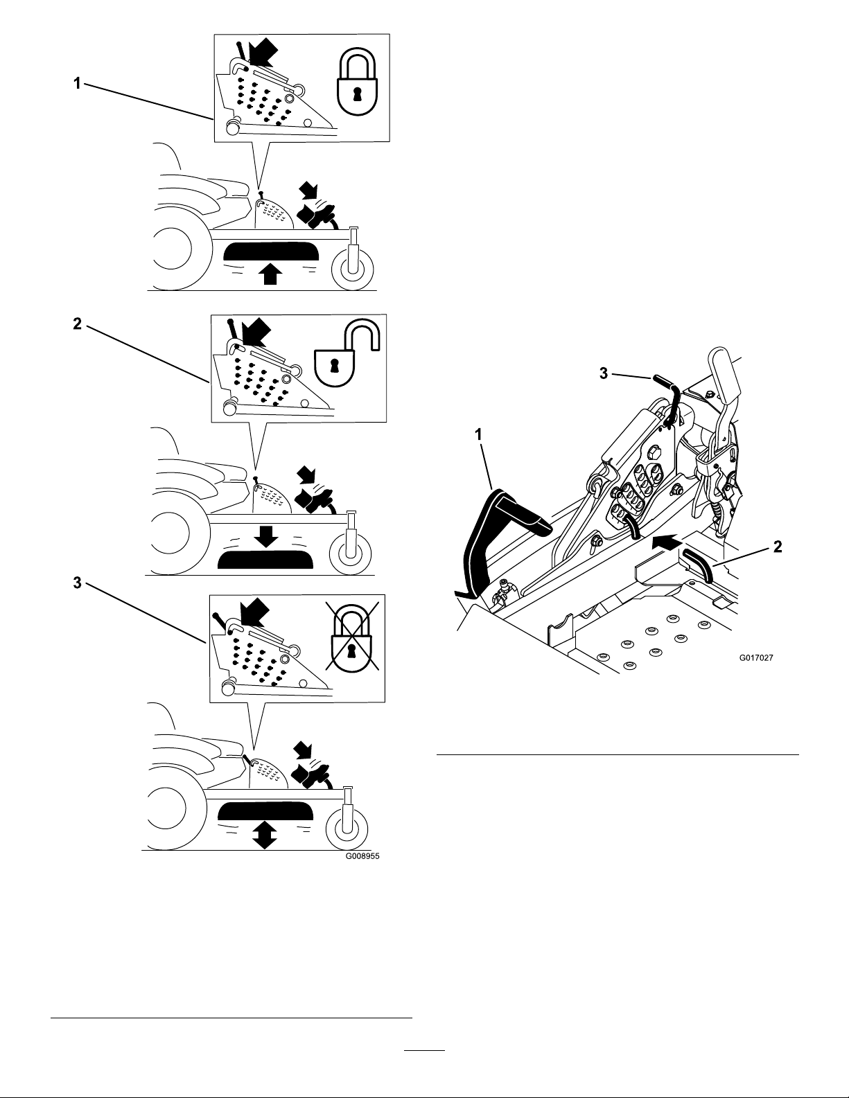
AdjustingtheFlowBafeCam
Locks
Thisprocedureisapplicableonlytomachineswiththeow
bafelocks.Certainmodelswillhavenutsandboltsin-place
oftheowbafelocksandcanbeadjustedthesame.
Themowerdischargeowcanbeadjustedfordifferenttypes
ofmowingconditions.Positionthecamlocksandbafeto
givethebestqualityofcut.
1.Disengagethebladecontrolswitch(PTO),movethe
motioncontrolleverstotheneutrallockedposition,
andsettheparkingbrake.
1.Anti-scalproller4.Flangenut
2.Spacer
3.Bushing
1.Anti-scalproller3.Flangenut
2.Bushing4.Bolt
5.Bolt
Figure27
2.Stoptheengine,removethekey ,andwaitforallmoving
partstostopbeforeleavingtheoperatingposition.
3.Toadjustthecamlocks,swingtheleveruptoloosen
thecamlock(Figure29).
4.Adjustthebafeandcamlocksintheslotstothe
desireddischargeow .
5.Swingtheleverbackovertotightenthebafeandcam
Figure29).
locks(
6.Ifthecamlocksdonotlockthebafeintoplaceorit
istootight,loosentheleverandthenrotatethecam
lock.Adjustthecamlockuntilthedesiredlocking
pressureisachieved.
Figure28
1.Anti-scalproller4.Flangenut
2.Spacer
3.Bushing
5.Bolt
1.Unlocklever
2.Rotatethecamlockto
increaseordecrease
lockingpressure
22
Figure29
3.Positionthebafe
4.Locklever
Page 23

PositioningtheFlowBafe
G008962
Thefollowingguresareonlyrecommendationsforuse.
Adjustmentswillvarybygrasstype,moisturecontent,and
heightofgrass.
Note:Iftheenginepowerdrawsdownandthemower
groundspeedisthesame,openupthebafe.
PositionA
Thisisthefullrearposition.Thesuggesteduseforthis
positionisafollows.
•Useforshort,lightgrassmowingconditions.
•Useindryconditions.
•Forsmallergrassclippings.
•Propelsgrassclippingsfartherawayfromthemower.
•Useintall,densegrassmowingconditions.
•Useinwetconditions.
•Lowerstheenginepowerconsumption.
•Allowsincreasedgroundspeedinheavyconditions.
•ThispositionissimilartothebenetsoftheToroSFS
mower.
Figure30
PositionB
Usethispositionwhenbagging.Alwaysalignitwiththe
bloweropening.
Figure32
PositioningtheSeat
Theseatcanmoveforwardandbackward.Positiontheseat
whereyouhavethebestcontrolofthemachineandaremost
comfortable.
Toadjust,movetheleversidewaystounlockseat(Figure33).
Figure33
Figure31
PositionC
Thisisthefullopenposition.Thesuggesteduseforthis
positionisasfollows.
23
Page 24

UsingtheDriveWheelRelease
g015123
Valves
4.Rotatethereleasevalvelevershorizontallytorunthe
machine(Figure34).
WARNING
Handsmaybecomeentangledintherotatingdrive
componentsbelowtheenginedeck,whichcould
resultinseriousinjury.
Stoptheengine,removethekey,andallowall
movingpartstostopbeforeaccessingthedrive
wheelreleasevalves.
WARNING
Theengineandhydraulicdriveunitscanbecome
veryhot.Touchingahotengineorhydraulicdrive
unitscancausesevereburns.
Allowtheengineandhydraulicdriveunitstocool
completelybeforeaccessingthedrivewheelrelease
valves.
Thedrivewheelreleasevalvesarelocatedinthebackofeach
hydraulicdriveunit,undertheseat.
Note:Makesurethereleasevalvesareinthefullyhorizontal
positionwhenoperatingthemachineorseveredamagetothe
hydraulicsystemcanoccur.
UsingtheSideDischarge
Themowerhasahingedgrassdeectorthatdisperses
clippingstothesideanddowntowardtheturf.
DANGER
Withoutagrassdeector,dischargecover,or
completegrasscatcherassemblymountedin
place,youandothersareexposedtobladecontact
andthrowndebris.Contactwithrotatingmower
blade(s)andthrowndebriswillcauseinjuryor
death.
•Neverremovethegrassdeectorfromthemower
becausethegrassdeectorroutesmaterialdown
towardtheturf.Ifthegrassdeectorisever
damaged,replaceitimmediately .
•Neverputyourhandsorfeetunderthemower.
•Nevertrytoclearthedischargeareaormower
bladesunlessyoumovethepowertakeoff(blade
controlswitch(PTO)totheoffposition,rotate
theignitionkeytooffandremovethekey.
•Makesurethegrassdeectorisinthedown
position.
1.DisengagethePTO(bladecontrolswitch)andturnthe
ignitionkeytooff.Movetheleverstoneutrallocked
positionandapplyparkingbrake.Removethekey.
2.Rotatethereleasevalveleversverticallytopushthe
machine.Thisallowshydraulicoiltoby-passthepump
enablingthewheelstoturn(Figure34).
3.Disengageparkingbrakebeforepushing.
Figure34
1.Verticaltopushthe
machine
2.Horizontaltorunthe
machine
LoadingMachines
Useextremecautionwhenloadingunitsontrailersortrucks.
Onefullwidthrampthatiswideenoughtoextendbeyond
thereartiresisrecommendedinsteadofindividualrampsfor
eachsideoftheunit(Figure35).Thelowerrearsectionof
themachineframeextendsbackbetweentherearwheelsand
servesasastopfortippingbackward.Havingafullwidth
rampprovidesasurfacefortheframememberstocontactif
theunitstartstotipbackward.Ifitisnotpossibletouseone
fullwidthramp,useenoughindividualrampstosimulatea
fullwidthcontinuousramp.
Therampshouldbelongenoughsothattheanglesdonot
exceed15degrees(
mowercomponentstogetcaughtastheunitmovesfrom
ramptotrailerortruck.Steeperanglesmayalsocausethe
unittotipbackward.Ifloadingonornearaslope,position
thetrailerortrucksoitisonthedownsideoftheslopeand
therampextendsuptheslope.Thiswillminimizetheramp
angle.Thetrailerortruckshouldbeaslevelaspossible.
Important:DoNotattempttoturntheunitwhileon
theramp;youmaylosecontrolanddriveofftheside.
Avoidsuddenaccelerationwhendrivinguparampand
suddendecelerationwhenbackingdownaramp.Both
maneuverscancausetheunittotipbackward.
Figure35).Asteeperanglemaycause
24
Page 25

WARNING
TransportingMachines
Loadingaunitontoatrailerortruckincreasesthe
possibilityofbackwardtip-overandcouldcause
seriousinjuryordeath.
•Useextremecautionwhenoperatingauniton
aramp.
•EnsuretheROPSisintheuppositionwhile
usingtheseatbeltwhenloadingthemachine.
EnsuretheROPSwillclearthetopofan
enclosedtrailer.
•Useonlyasingle,fullwidthramp;DoNotuse
individualrampsforeachsideoftheunit.
•Ifindividualrampsmustbeused,useenough
rampstocreateanunbrokenrampsurfacewider
thantheunit.
•Donotexceeda15degreeanglebetweenramp
andgroundorbetweenrampandtrailerortruck.
•Avoidsuddenaccelerationwhiledrivingunitup
aramptoavoidtippingbackward.
•Avoidsuddendecelerationwhilebackingunit
downaramptoavoidtippingbackward.
Useaheavy-dutytrailerortrucktotransportthemachine.
Ensurethatthetrailerortruckhasallnecessarybrakes,
lighting,andmarkingasrequiredbylaw.Pleasecarefullyread
allthesafetyinstructions.Knowingthisinformationcould
helpyou,yourfamily,petsorbystandersavoidinjury.
WARNING
Drivingonthestreetorroadwaywithoutturn
signals,lights,reectivemarkings,oraslow
movingvehicleemblemisdangerousandcanlead
toaccidentscausingpersonalinjury.
Donotdrivemachineonapublicstreetorroadway .
Totransportthemachine:
1.Ifusingatrailer,connectittothetowingvehicleand
connectthesafetychains.
2.Ifapplicable,connectthetrailerbrakes.
3.Loadthemachineontothetrailerortruck.
4.Stoptheengine,removethekey,setthebrake,and
closethefuelvalve.
5.Usethemetaltiedownloopsonthemachineto
securelyfastenthemachinetothetrailerortruckwith
straps,chains,cable,orropes(
Figure36).
Figure35
1.Trailer3.Notgreaterthan
15degrees
2.Fullwidthramp4.Fullwidthramp—sideview
Figure36
1.Tractionunittiedownloops
25
Page 26

OperatingTips
MaximizingCuttingEfciency
Forbestmowingandmaximumaircirculation,operate
theengineatthefastthrottleposition.Airisrequiredto
thoroughlycutgrassclippings,sodonotsettheheightof
cutsolowastototallysurroundthemowerbyuncutgrass.
Alwaystrytohaveonesideofthemowerfreefromuncut
grass,whichallowsairtobedrawnintothemower.
CuttingaLawnfortheFirstTime
Cutgrassslightlylongerthannormaltoensurethecutting
heightofthemowerdoesnotscalpanyunevenground.
However,thecuttingheightusedinthepastisgenerallythe
bestonetouse.Whencuttinggrasslongerthansixinchestall,
youmaywanttocutthelawntwicetoensureanacceptable
qualityofcut.
Cutting1/3oftheGrassBlade
Itisbesttocutonlyabout1/3ofthegrassblade.Cutting
morethanthatisnotrecommendedunlessgrassissparse,or
itislatefallwhengrassgrowsmoreslowly.
AlternatingMowingDirection
setting.Thencutthegrassagainusingthelower,normal
setting.
Stopping
Iftheyoumuststoptheforwardmotionofthemachine
whilemowing,aclumpofgrassclippingsmaydropontothe
lawn.Toavoidthis,moveontoapreviouslycutareawith
thebladesengaged.
KeepingtheUndersideoftheMower
Clean
Cleanclippingsanddirtfromtheundersideofthemower
aftereachuse.Ifgrassanddirtbuildupinsidethemower,
cuttingqualitywilleventuallybecomeunsatisfactory.
MaintainingtheBlade
Maintainasharpbladethroughoutthecuttingseasonbecause
asharpbladecutscleanlywithouttearingorshreddingthe
grassblades.Tearingandshreddingturnsgrassbrownat
theedges,whichslowsgrowthandincreasesthechanceof
disease.Checkthecutterbladesdailyforsharpness,andfor
anywearordamage.Filedownanynicksandsharpenthe
bladesasnecessary.Ifabladeisdamagedorworn,replaceit
immediatelywithagenuineTororeplacementblade.
Alternatemowingdirectiontokeepthegrassstanding
straight.Thisalsohelpsdisperseclippings,whichenhances
decompositionandfertilization.
MowingatCorrectIntervals
Normally,mowevery4days.However,grassgrowsat
differentratesatdifferenttimes.Sotomaintainthesame
cuttingheight,whichisagoodpractice,mowmoreoftenin
earlyspring.Asthegrassgrowthrateslowsinmidsummer,
mowlessfrequently .Ifyoucannotmowforanextended
period,rstmowatahighcuttingheight;thenmowagain2
dayslateratalowerheightsetting.
ChoosingtheBestSpeed
Toimprovecutquality ,useaslowergroundspeedincertain
conditions.
AvoidingCuttingTooLow
Ifthecuttingwidthofthemoweriswiderthanthemower
youpreviouslyused,raisethecuttingheighttoensurethat
uneventurfisnotcuttooshort.
CuttingLongGrass
Ifthegrassiseverallowedtogrowslightlylongerthan
normal,orifitcontainsahighdegreeofmoisture,raisethe
cuttingheighthigherthanusualandcutthegrassatthis
26
Page 27

Maintenance
RecommendedMaintenanceSchedule(s)
MaintenanceService
Interval
Aftertherst100hours
Aftertherst250hours
Beforeeachuseordaily
Every50hours
Every100hours
Every150hours
MaintenanceProcedure
•Checkthewheellugnuttorque.
•Checkthewheelhubslotted-nuttorque.
•Checktheparkbrakeadjustment.
•Changethehydraulicltersandhydraulicoilwhenusinganytypeofoil.
•Checkthesafetysystem.
•Checktheengineoillevel.
•Checktheseatbelt.
•Checktherolloverprotectionsystem(ROPS)knobs.
•Cleantheenginescreenandtheoilcooler.
•Checkandcleanthehydraulicunits.
•Checkthemowerblades.
•Cleanthemowerdeck.
•Greasethemowerdeckspindlesandidlerarm.
•Checkthesparkarrester(ifequipped).
•Checkthetirepressure.
•Inspectthebeltsforcracksandwear.
•Checkthehydraulicoillevel.
•Lubricatethemowerdeckliftpivots.
•Changetheengineoil.(moreoftenindirtyordustyconditions)
•Checkandcleanenginecoolingnsandshrouds.
•Inspecttheprimarylterandairinletscreen.
Every200hours
Every250hours
Every300hours
Every500hours
Every600hours
Yearlyorbeforestorage
•Changetheengineoillter.
•Cleantheengineoilcooler.
•Check,cleanandregapthesparkplug.
•Replacethefuellter.(moreoftenindirtyordustyconditions).
•ChangethehydraulicltersandhydraulicoilwhenusingMobil®1oil(moreoftenin
dirtyordustyconditions).
•Replacetheprimaryairlter.(moreoftenindustyorsandyconditions)
•Checktheinnerairlter.
•Checkthewheellugnuttorque.
•Checkthewheelhubslotted-nuttorque.
•Adjustthecasterpivotbearing.
•Checktheparkbrakeadjustment.
•ChangethehydraulicltersandhydraulicoilwhenusingT oro®HYPR-OIL™500
hydraulicoil(moreoftenindirtyordustyconditions).
•Replacetheinnerairlter.
Monthly
Yearly
•Checkthebattery .
•Greasethepumpbeltidlerarm.
•Greasethefrontcasterpivots(moreoftenindirtyordustyconditions).
•Repackthefrontcasterwheelbearings(moreoftenindirtyordustyconditions).
•Lubricatethecasterwheelhubs.
•Paintchippedsurfaces.
•Checkallmaintenanceprocedureslistedabovebeforestorage.
Important:Refertoyourengineoperator'smanualforadditionalmaintenanceprocedures.
27
Page 28

CAUTION
G017028
G017050
Ifyouleavethekeyintheignitionswitch,someonecouldaccidentlystarttheengineandseriouslyinjure
youorotherbystanders.
Removethekeyfromtheignitionbeforeyoudoanymaintenance.
Lubrication
LubricatingtheMachine
Greasemorefrequentlywhenoperatingconditionsare
extremelydustyorsandy .
GreaseType:No.2general-purposelithium-basedor
molybdenum-basedgrease
1.Disengagethebladecontrolswitch(PTO),movethe
motioncontrolleverstotheneutrallockedposition
andsettheparkingbrake.
2.Stoptheengine,removethekey ,andwaitforallmoving
partstostopbeforeleavingtheoperatingposition.
Figure38
3.Cleanthegreasettingswitharag.Makesuretoscrape
anypaintoffthefrontofthetting(s).
4.Connectagreaseguntothetting.Pumpgrease
intothettingsuntilgreasebeginstooozeoutofthe
bearings.
5.Wipeupanyexcessgrease.
AddingLightOilorSprayLubrication
ServiceInterval:Every100hours
Lubricatethedeckliftpivots.
GreasingtheMower
ServiceInterval:Every50hours—Greasethemowerdeck
spindlesandidlerarm.
Yearly—Greasethepumpbeltidlerarm.
Yearly—Greasethefrontcasterpivots(moreoftenin
dirtyordustyconditions).
Yearly—Repackthefrontcasterwheelbearings(more
oftenindirtyordustyconditions).
Important:Makesurethatthecuttingunitspindlesare
fullofgreaseweekly.
1.Disengagethebladecontrolswitch(PTO),movethe
motioncontrolleverstotheneutrallockedposition,
andsettheparkingbrake.
2.Stoptheengine,removethekey ,andwaitforallmoving
partstostopbeforeleavingtheoperatingposition.
3.Greasethemowerdeckidlerpulleypivotuntilgrease
comeoutthebottom(Figure39).
4.Greasethe3spindlebearingsuntilgreasecomesout
thelowerseals(Figure39).
Figure37
28
Page 29

G009029
g014942
Figure41
Figure39
5.Greasethedrivebeltidlerarm(Figure39).
Figure40
6.Removethedustcapandadjustthecasterpivots.
Note:Keepthedustcapoffuntilgreasingiscomplete.
RefertoAdjustingtheCasterPivotBearing(page40).
7.Removethehexplugandthreadagreasettinginto
thehole.
8.Pumpgreaseintothettinguntilitoozesoutaround
thetopbearing.
9.Removethegreasettingfromthehole.
10.Installthehexpluganddustcap(Figure41).
LubricatetheCasterWheel Hubs
ServiceInterval:Yearly
1.Stoptheengine,waitforallmovingpartstostop,and
removethekey .Engagetheparkingbrake.
Figure42
1.Sealguard2.Spacernutwithwrench
ats
2.Raisethefrontofthemachineupandsupportitwith
jackstands.
3.Removethecasterwheelfromthecasterforks.
4.Removethesealguardsfromthewheelhub.
5.Remove1ofthespacernutsfromtheaxleassembly
inthecasterwheel.
Note:Notethatthreadlockingadhesivehasbeen
appliedtolockthespacernutstotheaxle.Remove
theaxle(withtheotherspacernutstillassembledtoit)
fromthewheelassembly .
6.Pryouttheseals,andinspectthebearingsforwearor
damageandreplaceifnecessary.
7.Packthebearingswithageneral-purposegrease.
8.Insert1bearingand1newsealintothewheel.
Note:Thesealsmustbereplaced.
9.Iftheaxleassemblyhashadbothspacernutsremoved
(orbrokenloose),applyathreadlockingadhesiveto1
29
Page 30
spacernutandthreaditontotheaxlewiththewrench
g012996
3
4
1
2
atsfacingoutward.
EngineMaintenance
Note:Donotthreadthespacernutalloftheway
ontotheendoftheaxle.Leaveapproximately3mm
(1/8inch)fromtheoutersurfaceofthespacernutto
theendoftheaxleinsidethenut.
10.Inserttheassemblednutandaxleintothewheelonthe
sideofthewheelwiththenewsealandbearing.
11.Withtheopenendofthewheelfacingup,llthearea
insidethewheelaroundtheaxlefullofgeneral-purpose
grease.
12.Insertthesecondbearingandnewsealintothewheel.
13.Applyathreadlockingadhesivetothesecondspacer
nutandthreaditontotheaxlewiththewrenchats
facingoutward.
14.Torquethenutto8-9N-m(75-80in-lb),loosen,then
re-torqueto2-3N-m(20-25in-lb).
Note:Makesurethattheaxledoesnotextendbeyond
eithernut.
15.Installthesealguardsoverthewheelhubandinsert
thewheelintothecasterfork.Installthecasterbolt
andtightenthenutfully.
Important:T opreventsealandbearingdamage,check
thebearingadjustmentoften.Spinthecastertire.The
tireshouldnotspinfreely(morethan1or2revolutions)
orhaveanysideplay.Ifthewheelspinsfreely,adjustthe
torqueonthespacernutuntilthereisaslightamountof
drag.Applythreadlockingadhesive.
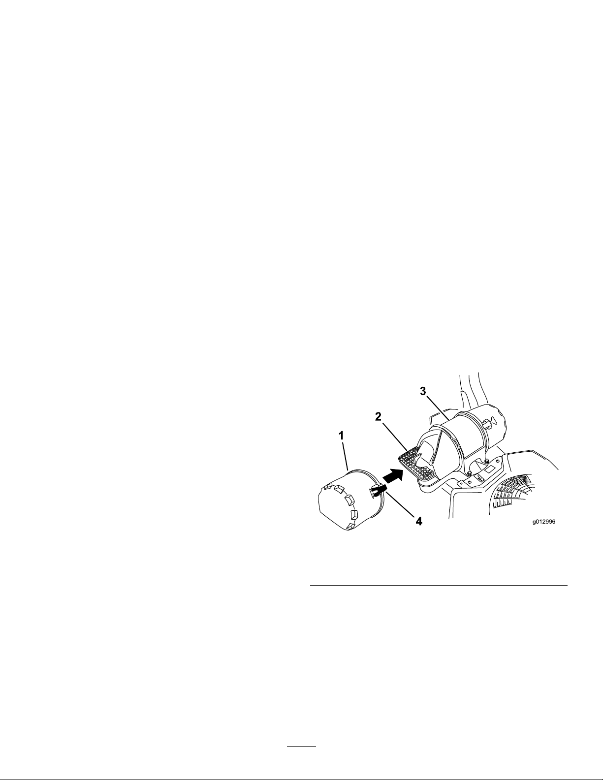
ServicingtheAirCleaner
ServiceInterval:Every150hours
Every300hours/Yearly(whichevercomes
rst)—Replacetheprimaryairlter.(moreoftenin
dustyorsandyconditions)
Every300hours—Checktheinnerairlter.
Every600hours—Replacetheinnerairlter.
Note:Checktheltersmorefrequentlyiftheoperating
conditionsareextremelydustyorsandy.
RemovingtheFilters
1.DisengagethePTO,movethemotioncontrolleversto
theneutrallockedposition,andsettheparkingbrake.
2.Stoptheengine,removethekey ,andwaitforallmoving
partstostopbeforeleavingtheoperatingposition.
3.Releasethelatchesontheaircleanerandpulltheair
inletcoverofftheaircleanerbody(Figure43).
4.Cleantheairinletscreenandcover.
5.Installtheairinletcoverandsecureitwiththelatches
(Figure43).
Figure43
1.Airinletcover3.Aircleanerbody
2.Airinletscreen4.Latch
6.Releasethelatchesontheaircleanerandpulltheair
cleanercoverofftheaircleanerbody(Figure44).
7.Cleantheinsideoftheaircleanercoverwith
30
compressedair.
8.Gentlyslidetheprimarylteroutoftheaircleaner
body(Figure44).
Note:Avoidknockingthelterintothesideofthe
body.
9.Removetheinnerlteronlyifyouintendtoreplaceit.
Page 31

Important:Neverattempttocleantheinnerlter.
g012997
1
2
3
4
5
Ifthesafetylterisdirty,thentheprimarylteris
damaged.Replacebothlters.
Figure44
Important:Donotpressonthesoftinsidearea
ofthelter.
4.Installtheaircleanercoverandsecurethelatches
(Figure44).
ServicingtheEngineOil
OilType:Detergentoil(APIserviceclassSJorhigher)
OilCapacity:withalterchange,58ounces(1.7L);withno
lterchange,48ounces(1.4L)
Viscosity:Seethetablebelow .
1.Innerlter
2.Primarylter
3.Aircleanercover
10.Inspecttheprimarylterfordamagebylookinginto
thelterwhileshiningabrightlightontheoutsideof
thelter.
Note:Theholesinthelterwillappearasbright
spots.Ifthelterisdamaged,discardit.
4.Latch
5.Aircleanerbody
ServicingthePrimaryFilter
•Iftheprimarylterisdirty,bent,ordamaged,replaceit.
•Donotcleantheprimarylter.
ServicingtheSafetyFilter
Replacethesafetylter,nevercleanit.
Important:Neverattempttocleanthesafetylter.
Ifthesafetylterisdirty,thentheprimarylteris
damaged.Replacebothlters.
InstallingtheFilters
Important:T opreventenginedamage,alwaysoperate
theenginewithbothairltersandcoverinstalled.
1.Ifinstallingnewlters,checkeachlterforshipping
damage.Donotuseadamagedlter.
2.Iftheinnerlterisbeingreplaced,carefullyslideitinto
thelterbody(Figure44).
3.Carefullyslidetheprimarylterovertheinnerlter
(Figure44).
Note:Ensurethattheprimarylterisfullyseatedby
pushingonitsouterrimwhileinstallingit.
Figure45
Note:Useofsyntheticoilhaving5W-20or5W -30ratingis
acceptable,upto4degreesC(40degreesF).
Note:Syntheticoilswillprovidebetterstartinginextreme
coldbelow-23degreesC(-10degreesF).
CheckingtheEngineOilLevel
ServiceInterval:Beforeeachuseordaily
Note:Checktheoilwhentheengineiscold.
WARNING
Contactwithhotsurfacesmaycausepersonal
injury.
Keephands,feet,face,clothingandotherbody
partsawayfromthemuferandotherhotsurfaces.
Important:Donotoverllthecrankcasewithoil
becausedamagetotheenginemayresult.Donotrun
enginewithoilbelowthelowmarkbecausetheengine
maybedamaged.
1.DisengagethePTO,movethemotioncontrolleversto
theneutrallockedpositionandsettheparkingbrake.
2.Stoptheengine,removethekey,andwaitforall
movingpartstostopbeforeleavingtheoperating
position(
Figure46).
31
Page 32

G008804
G008792
1
2
5
6
7
3
9
10
4
8
ChangingtheEngineOil
G008804
G008793
1
2
3
4
4
5
ServiceInterval:Every100hours(moreoftenindirtyor
dustyconditions)
Note:Disposeoftheusedoilatarecyclingcenter.
1.Parkthemachinesothattherearisslightlylowerthan
thefronttoensuretheoildrainscompletely .
2.DisengagethePTO,movethemotioncontrolleversto
theneutrallockedpositionandsettheparkingbrake.
3.Stoptheengine,removethekey,andwaitforall
movingpartstostopbeforeleavingtheoperating
position(
Figure47).
Figure46
Figure47
32
Page 33

4.Slowlypourapproximately80%ofthespeciedoil
G008796
2
3
4
5
6
1
G008804
G008748
3/4
1
2
3
4
5
6
intothellertubeandslowlyaddtheadditionaloilto
bringittotheFullmark(Figure48).
ChangingtheEngineOilFilter
ServiceInterval:Every200hours
Note:Changetheengineoilltermorefrequentlywhen
operatingconditionsareextremelydustyorsandy.
1.Draintheoilfromtheengine;refertoChangingthe
EngineOil(page32).
Figure48
5.Starttheengineanddrivetoaatarea.Checktheoil
levelagain.
2.Changetheengineoillter(
Figure49).
Figure49
Note:Ensuretheoilltergaskettouchestheengine
andthenanextra3/4turniscompleted.
3.Fillthecrankcasewiththepropertypeofnewoil;refer
to
ChangingtheEngineOil(page32).
33
Page 34

ServicingtheEngineOilCooler
G008804
g01301 1
1 2
2
ServicingtheSparkPlug
ServiceInterval:Every200hours
1.Keeptheoilcoolerfreeofdebris.bycleaningthens
withabrush.
2.Removetheboltsholdingtheoilcoolertotheengine
housing.
3.Cleantheinsideoftheoilcoolerwithabrush.
4.Installtheoilcoolertotheenginehousing.
ServiceInterval:Every200hours—Check,cleanandregap
thesparkplug.
Makesuretheairgapbetweenthecenterandsideelectrodes
iscorrectbeforeinstallingthesparkplug.Useasparkplug
wrenchforremovingandinstallingthesparkplug(s)anda
gappingtool/feelergaugetocheckandadjusttheairgap.
Installanewsparkplug(s)ifnecessary.
Type:Champion
®
XC12YC,orequivalent
AirGap:0.76mm(0.030inch)
RemovingtheSparkPlug
1.Stoptheengine,removethekey ,andwaitforallmoving
partstostopbeforeleavingtheoperatingposition.
2.DisengagethePTO,movethemotioncontrolleversto
theneutrallockedpositionandsettheparkingbrake.
3.Removethelefthydraulicunitshroudintheorder
listedwith
sparkplug.
Figure51.Thisgivesyouaccesstothefront
1.Engineoilcooler2.Bolts
Figure50
1.Pullthistabouttothe
sideinthedirectionofthe
arrow
2.Pulltheshroudoffofthis
frametabinthedirection
ofthearrow
Figure51
3.Pulltheshroudoffofthis
frametabinthedirection
ofthearrow
4.Shroud
34
Page 35

4.Removethesparkplug.
G008803
G008794
1
2
Figure54
ChecktheSparkArrester(if equipped)
ServiceInterval:Every50hours
Figure52
5.Installthelefthydraulicunitshroud(Figure51).
CheckingtheSparkPlug
Important:Replacethesparkplug(s)whenithas:a
blackcoating,wornelectrodes,anoilylm,cracksor
reuseisquestionable.
Ifyouseelightbrownorgrayontheinsulator,theengineis
operatingproperly.Ablackcoatingontheinsulatorusually
meanstheaircleanerisdirty.
Setthegapto0.76mm(0.030inches).
WARNING
Hotexhaustsystemcomponentsmayignite
gasolinevaporsevenaftertheengineisstopped.
Hotparticlesexhaustedduringengineoperation
mayigniteammablematerials.Firemayresultin
personalinjuryorpropertydamage.
Donotrefuelorrunengineunlesssparkarrester
isinstalled.
1.Stoptheengine,waitforallmovingpartstostop,and
removethekey .Engagetheparkingbrake.
2.Waitforthemachinetocool.
3.Ifthereareanybreaksinthescreenorweldsare
observed,replacethearrester.
4.Ifthescreenisplugged,removethearresterandshake
looseanyparticlesoutofthearresterandcleanthe
screenwithawirebrush(soakinsolventifnecessary).
Installthearresteronanexhaustoutlet.
Figure53
InstallingtheSparkPlug
Tightenthesparkplug(s)to24.4–29.8N-m(18-22ft.-lb).
35
Page 36

FuelSystem
G008963
12
3
Maintenance
WARNING
Fuelsystemcomponentsareunderhighpressure.
Theuseofimpropercomponentscanresultin
systemfailure,gasolineleakage,andpossible
explosion.
Useonlyapprovedfuellinesandfuellters.
ServicingtheElectronicFuel InjectionSystem
Thismachinecontainsanelectronicfuelinjectionsystem.It
controlsthefuelowunderdifferentoperatingconditions.
Theelectroniccontrolunit(ECU)continuouslymonitorsthe
operationoftheEFIsystem.
Ifaproblemorfaultwithinthesystemisdetected,the
malfunctionindicatorlight(MIL)isilluminated.TheMILis
theredlightlocatedintherightconsolepanel.
OncetheMILilluminates,initialtroubleshooting
checksshouldbemade.RefertotheMILsectionunder
Toubleshooting.
Ifthesechecksdonotcorrecttheproblem,furtherdiagnosis
andservicingbyanAuthorizedServiceDealerisnecessary.
ReplacingtheLowPressure FuelFilter
ServiceInterval:Every200hours/Yearly(whichevercomes
rst)(moreoftenindirtyordusty
conditions).
Thefuellterislocatedneartheengineonthefrontorrear
sideoftheengine.
1.DisengagethePTO,movethemotioncontrolleversto
theneutrallockedposition,andsettheparkingbrake.
2.Stoptheengine,removethekey ,andwaitforallmoving
partstostopbeforeleavingtheoperatingposition.
3.Allowthemachinetocooldown.
4.Stoptheengine,removethekey ,andwaitforallmoving
partstostopbeforeleavingtheoperatingposition.
5.Closethefuelshutoffvalveundertheseat(
Figure55).
Figure55
1.Fuellter
2.Hoseclamp
6.Squeezetheendsofthehoseclampstogetherandslide
themawayfromthelter(Figure55).
7.Removethelterfromthefuellines.
8.Installanewlterandmovethehoseclampscloseto
thelter(Figure55).
9.Openthefuelshutoffvalve.
Note:Itisimportanttoreinstallthefuellinehosesand
securewithplastictiesthesameastheywereoriginally
installedatthefactorytokeepthefuellineawayfrom
componentsthatcouldcausefuellinedamage.
3.Fuelline
ServicingtheHighPressure FuelFilter
Donotattempttoservicethehighpressurefuellter.The
highpressurelterisintegratedwithinthefuelpumpmodule.
Thefuellterandothercomponentsinsidethefuelpump
modulearenotserviceable.Donotattempttoopenthefuel
pumpmodule.
EnsurethatanAuthorizedServiceDealerreplacesthefuel
pumpmodulewiththehighpressurefuellter.
ServicingtheFuelTank
Donotattempttodrainthefueltank.Ensurethatan
AuthorizedServiceDealerdrainsthefueltankandservices
anycomponentsofthefuelsystem.
36
Page 37
ElectricalSystem
g014731
+
-
+
-
+
-
1
2
3
4
Maintenance
ServicingtheBattery
ServiceInterval:Monthly
WARNING
CALIFORNIA
Proposition65Warning
WARNING
Incorrectbatterycableroutingcoulddamagethe
machineandcablescausingsparks.Sparkscan
causethebatterygassestoexplode,resultingin
personalinjury.
•AlwaysDisconnectthenegative(black)battery
cablebeforedisconnectingthepositive(red)
cable.
•AlwaysReconnectthepositive(red)battery
cablebeforereconnectingthenegative(black)
cable.
Batteryposts,terminals,andrelated
accessoriescontainleadandleadcompounds,
chemicalsknowntotheStateofCalifornia
tocausecancerandreproductiveharm.
Washhandsafterhandling.
DANGER
Batteryelectrolytecontainssulfuricacidwhichisa
deadlypoisonandcausessevereburns.
Donotdrinkelectrolyteandavoidcontactwith
skin,eyesorclothing.Wearsafetyglassestoshield
youreyesandrubberglovestoprotectyourhands.
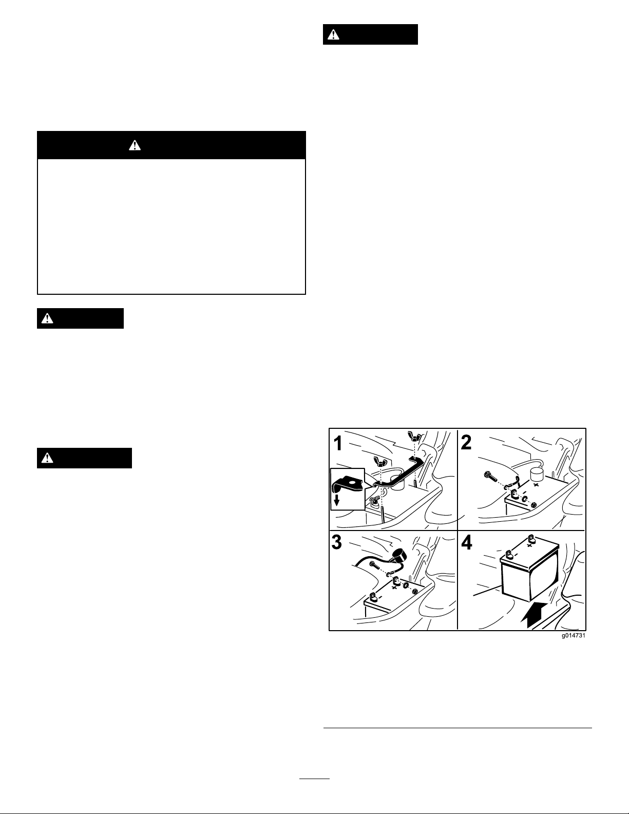
RemovingtheBattery
WARNING
Batteryterminalsormetaltoolscouldshortagainst
metalmachinecomponentscausingsparks.Sparks
cancausethebatterygassestoexplode,resulting
inpersonalinjury.
1.Disengagethebladecontrolswitch(PTO),movethe
motioncontrolleverstotheneutrallockedposition
andsettheparkingbrake.
2.Stoptheengine,removethekey ,andwaitforallmoving
partstostopbeforeleavingtheoperatingposition.
3.Firstdisconnectthenegativebatterycable(black)from
thenegative(-)(black)batteryterminal(
4.Slidetheredterminalbootoffthepositive(red)battery
terminalandremovethepositive(+)(red)batterycable
(Figure56).
5.Removethewingnutsecuringthebatteryclamp
(Figure56).
6.Removetheclamp(Figure56).
7.Removethebattery.
Figure56).
•Whenremovingorinstallingthebattery,donot
allowthebatteryterminalstotouchanymetal
partsofthemachine.
•Donotallowmetaltoolstoshortbetween
thebatteryterminalsandmetalpartsofthe
machine.
1.Removethewingnutand
clamp
2.Removethenegative
batterycablebeforethe
positive
37
Figure56
3.Removethepositive
batterycable
4.Removebattery
Page 38

InstallingtheBattery
g020464
1.Positionbatteryinthetraywiththeterminalposts
oppositefromthehydraulictank(Figure56).
2.First,installthepositive(red)batterycabletopositive
(+)batteryterminal.
3.Theninstallthenegative(black)batterycableand
groundwiretothenegative(-)batteryterminal.
4.Securethecableswith2bolts,2washers,and2locknuts
Figure56).
(
5.Slidetheredterminalbootontothepositive(red)
batterypost.
6.Installtheclampandsecureitwiththewingnut(Figure
56).
ChargingtheBattery
WARNING
Chargingthebatteryproducesgassesthatcan
explode.
Neversmokenearthebatteryandkeepsparksand
amesawayfrombattery.
Important:Alwayskeepthebatteryfullycharged
(1.265specicgravity).Thisisespeciallyimportantto
preventbatterydamagewhenthetemperatureisbelow
32°F(0°C).
1.Chargebatteryfor10to15minutesat25to30amps
or30minutesat10amps.
2.Whenthebatteryisfullycharged,unplugthecharger
fromtheelectricaloutlet,thendisconnectthecharger
leadsfromthebatteryposts(Figure57).
3.Installthebatteryinthemachineandconnectthe
batterycables,refertoInstallingtheBattery(page38).
Figure57
1.PositiveBatteryPost
2.NegativeBatteryPost
3.Red(+)ChargerLead
4.Black(-)ChargerLead
ServicingtheFuses
Theelectricalsystemisprotectedbyfuses.Itrequires
nomaintenance,however,ifafuseblowscheckthe
component/circuitforamalfunctionorshort.
1.Thefusesarelocatedonrighthandconsolenextto
theseat(Figure58).
2.Toreplacethefuses,pulloutonthefusetoremoveit.
3.Installanewfuse(Figure58).
Note:Donotrunthemachinewiththebattery
disconnected,electricaldamagemayoccur.
1.Optionalaccesory-15amp
2.Charge-25amp5.Console
3.PTO-10amp
38
Figure58
4.Main-25amp
Page 39

DriveSystem
Maintenance
CheckingtheSeatBelt
ServiceInterval:Beforeeachuseordaily
Visuallyinspectseatbeltforwear,cuts,andproperoperation
ofretractorandbuckle.Replacebeforeoperatingifdamaged.
CheckingtheRollover ProtectionSystem(ROPS) Knobs
ServiceInterval:Beforeeachuseordaily
WARNING
Toavoidinjuryordeathfromrollover:keeptheroll
barinthefullyraisedlockedpositionandusethe
seatbelt.
Ensuretheseatissecuredtothemachine.
Checkthatboththemountinghardwareandtheknobsare
ingoodworkingcondition.Makesuretheknobsarefully
engagedwiththeROPSintheraisedposition.Theupper
hoopoftherollbarmayneedtobepushedforwardorpulled
rearwardtogetbothknobsfullyengaged.
Figure59
1.ROPSknob(locked
position)
2.PullROPSknoboutand
rotate90degreesto
changerollbarposition
3.Rollbarintheupright
position
4.Rollbarinthefolded
position
AdjustingtheTracking
1.Disengagethebladecontrolswitch(PTO).
2.Drivetoanopenatarea,movethemotioncontrol
leverstotheneutrallockedposition.
3.Movethethrottlemidwaybetweenfastandslow.
4.Movebothmotioncontrolleversallthewayforward
untiltheybothhitthestopsintheT-slot.
5.Checkwhichwaythemachinetracks.
6.Ifittrackstotheright,loosentheboltsandadjust
theleftstopplaterearwardontheleftT-slotuntilthe
machinetracksstraight(Figure60).
7.Ifittrackstotheleft,loosentheboltsandadjustthe
rightstopplaterearwardontherightT-slotuntilthe
machinetracksstraight(Figure60).
8.Tightenthestopplate(Figure60).
39
Page 40

CheckingtheWheelLugNuts
Checkandtorquethewheellugnutsto122-129N-m(90-95
ft-lb).
CheckingtheWheelHub SlottedNut
ServiceInterval:Aftertherst100hours
Every500hours
Checkandensurethatthetorqueoftheslottednutis286to
352N-m(211to260ft-lb).
Note:Donotuseanti-seizeonwheelhub.
Figure60
Leftcontrollevershown
1.Controllever3.Stopplate
2.Bolt
CheckingtheTirePressure
ServiceInterval:Every50hours/Monthly(whichever
comesrst)
Maintaintheairpressureinthefrontandreartiresat13psi
(90kPa).Uneventirepressurecancauseunevencut.Check
thetireswhentheyarecoldtogetthemostaccuratepressure
reading.
Figure62
1.Slottednut
AdjustingtheCasterPivot Bearing
ServiceInterval:Every500hours/Yearly(whichevercomes
rst)
Figure61
1.Disengagethebladecontrolswitch(PTO),movethe
motioncontrolleverstotheneutrallockedposition
andsettheparkingbrake.
2.Stoptheengine,removethekey ,andwaitforallmoving
partstostopbeforeleavingtheoperatingposition.
3.Removethedustcapfromcasterandtightenlocknut
(
Figure63).
40
Page 41

4.Tightenthelocknutuntilthespringwashersareatand
thenbackoffa1/4turntoproperlysetthepre-loadon
thebearings(Figure63).
Important:Makesurethespringwashersare
installedcorrectlyasshowninFigure63.
5.Installthedustcap(Figure63).
Figure63
1.SpringWashers3.DustCap
2.LockNut
UsingtheClutchShim
RemovingtheClutchShim
1.Stoptheengine,waitforallmovingpartstostop,and
removethekey .
2.Engagetheparkingbrakeandallowthemachineto
coolcompletelybeforestartingtheseinstructions.
3.Usinganaircompressor,blowoutanydebrisfrom
underthebrakepoleandaroundthebrakespacers.
Figure65
4.Checktheconditionofthewireharnessleads,
connectors,andterminals.Cleanorrepairasnecessary.
5.Verifythat12Vispresentattheclutchconnectorwhen
thePTOswitchisengaged.
6.Measurethegapbetweentherotorandarmature.If
thegapisgreaterthan1mm(0.04inch),proceedwith
thefollowingsteps:
A.Loosenbothbrakemountingboltsone-halfto
onefullturnasshownbelow .
Somelatermodelyearunitshavebeenbuiltwithclutchesthat
containabrakeshim.Whentheclutchbrakehasworntothe
pointwheretheclutchnolongerengagesconsistently ,the
shimcanberemovedtoextendtheclutchlife.
Figure64
1.Armature5.Brakespacer
2.Fieldshell6.Re-gapshim
3.Rotor7.Brakepole
4.Brakemountingbolt
Note:Donotremovethebrakepolefromthe
eldshell/armature.Thebrakepolehasworn
tomatchthearmatureandneedstocontinueto
matchaftertheshimisremovedtoensureproper
braketorque.
Figure66
1.Brakemountingbolt
B.Usingneedlenosepliers,orbyhand,takehold
ofthetab,andremovetheshim(Donotdiscard
theshimuntilproperclutchfunctionhasbeen
conrmed).
41
Page 42

F.Performthefollowingsafetycheck:
i.Sitontheseatandstarttheengine.
ii.MakesurethebladesDonotengagewith
thePTOswitch“off”andtheclutch
disengaged.
Iftheclutchdoesnotdisengage,installthe
shim,andreferencethe
(page59)section.
Troubleshooting
Figure67
1.Shim
C.Usingapneumaticline,blowoutanydebris
fromunderthebrakepoleandaroundthebrake
spacers.
D.Re-torqueeachbolt(M6x1)to13N-m(10ft-lb
+/-0.7N-m(0.5ft-lb).
E.Usinga0.010inchthickfeelergauge,verifythat
agapispresentbetweentherotorandarmature
faceonbothsidesofthebrakepoleasshown.
Note:Duetothewaytherotorandarmature
faceswear(peaksandvalleys)itissometimes
difculttomeasurethetruegap.
iii.EngageanddisengagethePTOswitch
10consecutivetimestoensuretheclutch
isfunctioningproperly .Iftheclutch
doesnotengageproperly,reference
theTroubleshooting(page59)section.
1.Feelergauge
1.Feelergauge
Figure68
Figure69
•Ifthegapislessthan0.010inch,thenreinstall
theshimandreferencetheTroubleshooting
(page59)section.
•Ifthegapissufcient,proceedtothesafety
checkinstepF.
42
Page 43

CoolingSystem
G008804
Maintenance
CleaningtheEngineScreen andEngineOilCooler
ServiceInterval:Beforeeachuseordaily
Removeanybuild-upofgrass,dirt,orotherdebrisfromthe
oilcooler(Figure70).
Figure71
1.Engineguard4.Fanhousing
2.Engineairintakescreen
3.Bolt
5.Screw
Figure70
Beforeeachuseremoveanybuild-upofgrass,dirt,or
otherdebrisfromtheenginescreen.Thiswillhelpensure
adequatecoolingandcorrectenginespeedandwillreduce
thepossibilityofoverheatingandmechanicaldamagetothe
engine(Figure71).
CleaningtheEngineCooling FinsandShrouds
ServiceInterval:Every100hours/Yearly(whichevercomes
rst)
1.DisengagethePTOandsettheparkingbrake.
2.Stoptheengine,removethekey ,andwaitforallmoving
partstostopbeforeleavingtheoperatingposition.
3.Removetheairintakescreen,recoilstarter,andfan
housing(Figure71).
4.Cleanthedebrisandgrassfromtheengineparts.
5.Installairintakescreen,recoilstarter,andfanhousing
(
Figure71).
CheckandCleantheHydraulic Units
ServiceInterval:Beforeeachuseordaily
1.DisengagethePTOandsettheparkingbrake.
2.Stoptheengine,removethekey ,andwaitforallmoving
partstostopbeforeleavingtheoperatingposition.
3.Movetheseatforward.
4.Cleanthedebrisandgrassfromthehydraulicunits
(Figure72).
5.Positiontheseat.
43
Page 44
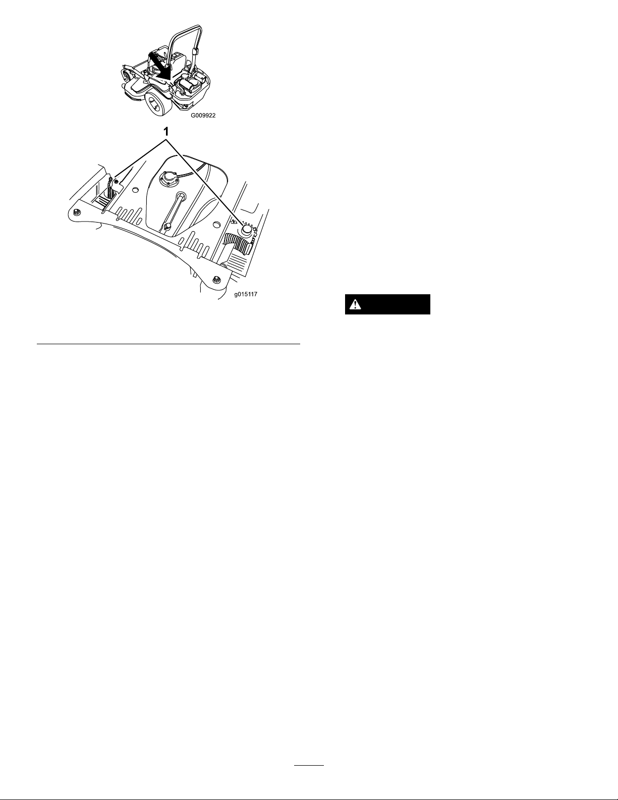
g0151 17
BrakeMaintenance
AdjustingtheParkingBrake
ServiceInterval:Aftertherst100hours
Every500hoursthereafter
Checktomakesurebrakeisadjustedproperly .Perform
thisprocedureaftertherst100hoursorwhenabrake
componenthasbeenremovedorreplaced.
1.Drivethemachineontoalevelsurface.
2.Disengagethebladecontrolswitch(PTO),movethe
motioncontrolleverstotheneutrallockedposition
andsettheparkingbrake.
3.Stoptheengine,waitforallmovingpartstostop,and
removethekey .
4.Raisethebackofthemachineupandsupportthe
machinewithjackstands.
1.Hydraulicunits
Figure72
DANGER
Mechanicalorhydraulicjacksmayfailto
supportmachineandcauseaseriousinjury.
•Usejackstandwhensupportingmachine.
•Donotusehydraulicjacks.
5.Removethereartiresfromthemachine.
6.Removeanydebrisfromthebrakearea.
7.Rotatethedrivewheelreleasehandletothereleased
position.RefertoUsingtheDriveWheelRelease
Valves(page24).
8.Measuretheoveralllengthofthecompressionspring.
Ensurethecorrectlengthisbetween3.8and4.0cm
(1-1/2and1-9/16inches).Ifthespringlengthis
withinthisrange,noadjustmentisneeded.Ifitisnot,
proceedtostep9.
9.Holdthethreadedrodendwithatoolandadjustthe
locknutuntilthespringlengthisbetween3.8and4.0
cm(1-1/2and1-9/16inches)(Figure73).Donotallow
thecabletoturnwhenthenutsarebeingloosened.
44
Page 45

Figure73
G009036
1
2
LeftHandBrakeShown
1.Cableanchor5.Caliper
2.Holdthreadedrodhere
3.Measure7.Threadedrod
4.Locknut8.Hub
10.Disengagetheparkbrake.Turnthewheelhubbyhand
inbothdirectionsrelativetothecaliper;nodragofthe
caliperpadonthewheelhubisdesired.
6.Compressionspring
BeltMaintenance
InspectingtheBelts
ServiceInterval:Every50hours
Checkthebeltsforsquealingwhenthebeltisrotating,blades
slippingwhencuttinggrass,frayedbeltedges,burnmarks,
andcracksaresignsofawornmowerbelt.Replacethe
mowerbeltifanyoftheseconditionsareevident.
ReplacingtheMowerBelt
Squealingwhenthebeltisrotating,bladesslippingwhen
cuttinggrass,frayedbeltedges,burnmarksandcracksare
signsofawornmowerbelt.Replacethemowerbeltifanyof
theseconditionsareevident.
1.DisengagethePTO,movethemotioncontrolleversto
theneutrallockedposition,andsettheparkingbrake.
2.Stoptheengine,removethekey ,andwaitforallmoving
partstostopbeforeleavingtheoperatingposition.
3.Lowerthemowertothe76mm(3inch)heightofcut.
4.Removethebeltcovers(Figure74).
11.Ifthereisnomovementbetweenthehubandthe
caliperthenrepeattheadjustment(ensurethedrive
releasevalvesareinthereleasedpositiononthe
hydros).
12.Afteradjustingthebrakesonbothsidesofthemower,
cyclethebrakehandleaminimumof6timestoallow
thecabletoseatintothesheathandmountingtabs.
13.Recheckthespringlength;engagetheparkbrakeand
repeatsteps8through11ifthelengthisnotinthe
correctrange.
14.Rotatethedrivewheelreleasehandletotheoperating
position.RefertoUsingtheDriveWheelRelease
Valves(page24).
15.Installthereartiresandtorquelugnutsbetween122
and129N-m(90and95ft-lb).
16.Removejackstands.
Figure74
1.Pushtabdown2.Removebeltcover
5.Usearatchetinthesquareholeintheidlerarmto
removetensionontheidlerspring(Figure75).
6.Removethebeltfromthemowerdeckpulleys.
7.Removethebeltguideonthespringloadedidlerarm
showninFigure75.
8.Removetheexistingbelt.
9.Installthenewbeltaroundthemowerpulleysandthe
clutchpulleyundertheengine(Figure75).
45
Page 46

Figure76
Figure75
1.Clutchpulley5.Squareholeintheidler
2.Mowerbelt
3.Springloadedidlerpulley
4.Ratchet
armfortheratchet
6.Idlergreasetting
7.Beltguide
10.InstallthebeltguideontheidlerarmshowninFigure
75.
11.Usingtheratchetinthesquarehole,installtheidler
spring(Figure75).
Makesurethatthespringendsareseatedintheanchor
grooves.
12.Installthebeltcovers(Figure76).
1.Positionthebeltcover3.Ensurethetabisunder
2.Slidebeltcoverunderthe
sidecatches
themetalcatch
ReplacingtheHydraulicPump DriveBelt
1.DisengagethePTOandsettheparkingbrake.
2.Stoptheengine,removethekey ,andwaitforallmoving
partstostopbeforeleavingtheoperatingposition.
3.Removemowerbelt.Referto
Belt(page45).
4.Raisethemachineandsupportitwithjackstands
(Figure77).
ReplacingtheMower
46
Page 47

Figure77
1.Idlerpulley
2.Clutchpulley6.Squareholeinidlerarm
3.Pumpdrivebelt7.Idlerspring
4.Righthandhydraulicpump
pulley
5.Lefthandhydraulicpump
pulley
ControlsSystem
Maintenance
AdjustingtheControlHandle Position
Thereare2heightpositionsforthecontrollevers;highand
low .Removetheboltstoadjusttheheightfortheoperator.
1.DisengagethePTO,movethemotioncontrolleversto
theneutrallockedposition,andsettheparkingbrake.
2.Stoptheengine,removethekey ,andwaitforallmoving
partstostopbeforeleavingtheoperatingposition.
3.Loosentheboltsandangenutsinstalledinthelevers
(Figure78).
4.Aligntheleversfronttorearpositionbybringthe
leverstogethertotheneutralpositionandslidethem
untiltheyarealigned,thentightenthebolts(Figure79).
5.Usearatchetinthesquareholeintheidlerarmto
removetheidlerspring(Figure77).
6.Unhooktheidlerspringfromtheframe(Figure77).
7.Removethebeltfromthehydraulicunitdrivepulleys
andtheenginepulley
8.Installthenewbeltaroundenginepulleyandthe2
drivepulleys.
9.Usingaratchetinthesquareholeintheidlerarm,
installtheidlerspringtotheframe(Figure77).
10.Installthemowerbelt.RefertoReplacingtheMower
Belt(page45).
Figure78
1.Bolt
2.Handle4.Nut
3.Controllever
47
Page 48

Figure79
AdjustingtheMotionControl
engine.Theoperatordoesnothavetobeinthe
seatbecauseofthejumperwirebeingused.Run
theengineatfullthrottleandreleasethebrake.
6.Runthemachineatleast5minuteswiththe
motion-controlleversatfullforwardspeedtobringthe
hydraulicoiluptooperatingtemperature.
Note:Themotion-controlleverneedstobeinneutral
whilemakinganynecessaryadjustments.
7.Bringthemotion-controlleversintotheneutral
position.
8.Adjustthepumpcontrolrodlengthsbyrotatingthe
doublenutsontherodintheappropriatedirection
untilthewheelsslightlycreepinreverse(
Figure80).
Linkage
Locatedoneithersideofthefueltank,belowtheseatare
thepumpcontrollinkages.Rotatingthepumplinkagewitha
1/2inchwrenchallowsne-tuningadjustmentssothatthe
machinedoesnotmoveinneutral.Anyadjustmentsshould
bemadeforneutralpositioningonly .
WARNING
Theenginemustberunningandthedrivewheels
mustbeturningsothatthemotion-control
adjustmentcanbeperformed.Contactwithmoving
partsorhotsurfacesmaycausepersonalinjury.
Keepngers,hands,andclothingclearofrotating
componentsandhotsurfaces.
1.Priortostartingtheengine,pushthedeck-liftpedal
andremovetheheight-of-cutpin.Lowerthedeckto
theground.
2.Raisetherearofmachineupandsupportitwithjack
stands(orequivalentsupport)justhighenoughto
allowthedrivewheelstoturnfreely .
3.Removetheelectricalconnectionfromtheseatsafety
switch,locatedunderthebottomcushionoftheseat.
Note:Theswitchisapartoftheseatassembly.
4.Temporarilyinstallajumperwireacrosstheterminals
intheconnectorofthemainwiringharness.
5.Starttheengine.
Note:Thebrakemustbeengagedandthe
motion-controlleversmustbeouttostartthe
Figure80
1.Doublenuts
9.Movethemotion-controlleverstothereverseposition,
andwhileapplyingslightpressuretothelever,allow
thereverseindicatorspringstobringtheleversback
toneutral.
Note:Thewheelsmuststopturningorslightlycreep
inreverse.
10.Shutoffthemachine.Removethejumperwirefrom
wireharnessandplugtheconnectorintotheseat
switch.
11.Removethejackstands.
12.Raisethedeckandinstalltheheight-of-cutpin.
13.Checkthatthemachinedoesnotcreepinneutralwith
theparkbrakesdisengaged.
48
Page 49

AdjustingtheMotion-control Damper
Thetopdamper-mountingboltcanbeadjustedtoobtaina
moredesiredmotion-controlleverresistance.SeeFigure81
formountingoptions.
Figure81
RHMotionControlShown
1.T orquethelocknutto23N-m(17ft-lb).Theboltmust
protrudepasttheendofthelocknutaftertorquing.
2.Mostresistance(rmestfeel)
3.Damper
4.Mediumresistance(mediumfeel)
5.Leastresistance(softestfeel)
Figure82
1.Flangednut2.Jamnut
AdjustingtheMotionControl NeutralLockPivot
Theangednutcanbeadjustedtoobtainamoredesired
motioncontrolleverresistancewhenmovingittotheneutral
lockposition.SeeFigure82foradjustmentoptions.
1.Loosenthejamnut.
2.Tightenorloosentheangednuttothedesiredfeel.
Formoreresistance,tightentheangednut.
Forlessresistance,loosentheangednut
3.Tightenthejamnut.
49
Page 50

HydraulicSystem
G015459
H
3
4
Maintenance
ServicingtheHydraulic System
HydraulicOilType:Toro
orMobil
Important:Useoilspecied.Otheruidscouldcause
systemdamage.
EachHydraulicSystemOilCapacity:52ounces(1.5l)per
sidewithlterchange
®
115W-50.
®
HYPR-OIL
™
500hydraulicoil
CheckingtheHydraulicOil
ServiceInterval:Every50hours—Checkthehydraulicoil
level.
1.Positionthemachineonalevelsurface.
2.DisengagethePTO,movethemotion-controlleversto
theneutral-lockedposition,andsettheparkingbrake.
3.Stoptheengine,removethekey ,andwaitforallmoving
partstostopbeforeleavingtheoperatingposition.
4.Allowtheengineandhydraulicsystemtocoolfor10
minutes.
Note:Theoillevelonthedipstickwillbeincorrectif
theoilischeckedwhenthemachineishot.
5.Movetheseatforward.
6.Cleantheareaaroundthedipsticksofthehydraulic
systemreservoirs(Figure83).
Figure83
Eitherdipstickwillbeusedinthemachine
1.Full3.H—meanshighlevel
2.Add4.Dipsticklocationsunder
seat
WARNING
Hydraulicoilescapingunderpressurecan
penetrateskinandcauseinjury.
7.Removeonedipstickfromthehydraulicreservoir
Figure83).
(
8.Wipethedipstickoffandthreadthedipstickintothe
reservoir.
9.Removethedipstickandlookattheend(Figure83).
Note:Iftheoillevelisattheaddmark,slowlypour
onlyenoughoilintothehydraulicreservoirtoraisethe
leveltothefullorHline.
Important:Donotoverllthehydraulicunits
withoilasdamagemayoccur.Donotrunthe
machinewiththeoilbelowtheaddmark.
10.Installthedipstick.
11.Repeatprocedurefortheoppositedipstick.
•Ifhydraulicoilisinjectedintotheskinit
mustbesurgicallyremovedwithinafew
hoursbyadoctorfamiliarwiththistype
ofinjury.Gangrenemayresultifthisis
notdone.
•Keepbodyandhandsawayfrompinhole
leaksornozzlesthatejecthighpressure
hydraulicoil.
•Usecardboardorpapertondhydraulic
leaks.
•Safelyrelieveallpressureinthehydraulic
systembeforeperforminganyworkonthe
hydraulicsystem.
•Makesurethatallhydraulicoilhosesand
linesareingoodconditionandthatall
hydraulicconnectionsandttingsaretight
beforeapplyingpressuretothehydraulic
system.
50
Page 51

ReplacingtheHydraulicFiltersand
G008968
1
2
HydraulicOil
ServiceInterval:Aftertherst250hours—Changethe
hydraulicltersandhydraulicoilwhen
usinganytypeofoil.
Every250hours—Changethehydraulicltersand
hydraulicoilwhenusingMobil
®
1oil(moreoftenin
dirtyordustyconditions).
Every500hours—Changethehydraulicltersand
hydraulicoilwhenusingToro
®
HYPR-OIL
™
hydraulicoil(moreoftenindirtyordustyconditions).
Toreplacethehydraulicoil,theltersneedtoberemoved.
Replacebothatthesametime;refertoServicingthe
HydraulicSystem(page50)
fortheoilspecications.
1.Disengagetheblade-controlswitch(PTO),movethe
motion-controlleverstotheneutral-lockedposition,
andsettheparkingbrake.
2.Stoptheengine,removethekey ,andwaitforallmoving
partstostopbeforeleavingtheoperatingposition.
3.Raisethemachineandsupportitwithjackstands
(Figure84).
500
Figure85
Bottomviewofthemachine
1.Filterlocations
2.Hydrauliclter
6.Applyathincoatofhydraulicoiltotherubbergasket
onthereplacementlter(Figure85).
7.Installthereplacementhydrauliclter.
8.Installthepump-drivebeltandthemowerbelt.
Figure84
1.Jackstands
4.Removeboththemowerbeltandthepump-drive
belt;refertoReplacingtheMowerBelt(page45)and
ReplacingtheHydraulicPumpDriveBelt(page46).
Note:Thispreventsoilfromgettingonthebelts.
5.Placeadrainpanunderthelter,removetheoldlter,
andwipethesurfaceclean(
Figure85).
9.Removethejackstandsandlowerthemachine(Figure
84).
10.Addoiltothehydraulicreservoirandcheckforany
leaks.
11.Cleanupanyspilledoil.
12.Starttheengineandletitrunforabout2minutesto
purgeairfromthesystem.
13.Stoptheengineandcheckforleaks.
14.Checktheoillevelwhiletheoiliscold.
15.Ifrequired,addoiltothehydraulicreservoir.
Note:Donotoverll.
51
Page 52

MowerDeck
1
3
2
G017027
Maintenance
LevelingtheMowerDeck
SettingUptheMachine
Note:Ensurethemowerdeckisleveledbeforematchingthe
height-of-cut(HOC).
1.Positionmoweronaatsurface.
2.Disengagethebladecontrolswitch(PTO),movethe
motioncontrolleverstotheneutrallockedposition
andsettheparkingbrake.
3.Stoptheengine,removethekey ,andwaitforallmoving
partstostopbeforeleavingtheoperatingposition.
4.Checktirepressureofthetires.Ifneeded,adjustto
13psi(90kPa)
5.Positionthemowertothe3inch(76mm)height-of-cut
position.
DeckLeveling
1.Positionthemoweronaatsurface.
2.Stopengine,waitforallmovingpartstostop,and
removekey.Engageparkingbrake.
3.Checkthetirepressureinthedrivetires.Proper
inationpressurefortiresis13psi(90kPa).Adjust
ifnecessary.
4.Positionthetransportlockinthelatchingposition.
5.Pushthedeckliftpedalallthewayforwardandthe
deckwilllatchatthe51/2inch(14cm)transport
position(
Figure86).
Figure86
1.Deckliftpedal
2.Heightofcutpin
6.Inserttheheightadjustmentpinintothe3inch(7.6
cm)cuttingheightlocation.
7.Releasethetransportlockandallowthedecktolower
tothecuttingheight.
8.Raisethedischargechute.
9.Onbothsidesofthedeck,measurefromthelevel
surfacetothefronttipoftheblade(PostionA).The
measurementshouldread3inches(7.6mm)(Figure
87).
3.Transportlock
Figure87
1.3inches(7.6cm)atAis
correct
2.31/4inches(8.3cm)atB
iscorrect
52
3.Measureherefromthe
bladetiptohardsurface
4.MeasureatAandBon
bothsides
Page 53

10.Ifneeded,loosenthewhizlocknutonthesideofthe
1
g017029
g017036
yokeandthejamnutontop.Finetunethescrew
adjusterbyturningittoget3inch(7.6mm)height(see
Figure88).
13.Ifthedeckistoolow ,tightenthesinglepoint
adjustmentboltbyrotatingitclockwise.Ifthedeckis
toohigh,loosenthesinglepointadjustmentboltby
rotatingitcounterclockwise(Figure90).
Toincreasetheheight,turntheadjusterscrew
clockwise;todecrease,turncounterclockwise.
Figure88
1.Whizlocknut3.Jamnut
2.Adjusterscrew4.Y oke
11.Ifthefrontdecklinksdonothaveenoughadjustment
toachieveaccuratecutheight,thesinglepoint
adjustmentcanbeutilizedtogainmoreadjustment.
12.Toadjustthesinglepointsystem,loosenthetwobolts
atthebottomoftheheightofcutplate.RefertoFigure
89.
Note:Loosenortightenthesinglepointadjustment
boltenoughtomovetheheight-of-cutplatemounting
boltsatleast1/3thelengthoftheavailabletravel
intheirslots.Thiswillregainsomeupanddown
adjustmentoneachofthefourdecklinks.
Figure90
1.Singlepointadjustmentbolt
14.Tightenthetwoboltsatthebottomoftheheightofcut
plate(Figure89).Torqueto27-33ft-lb(37-45N-m).
Note:Inmostconditions,thebackbladetipshould
beadjusted1/4inch(6.4mm)higherthanthefront.
Figure89
1.Boltsatthebottomoftheheight-of-cutplate
15.Onbothsidesofthedeck,measurefromthelevel
surfacetothebacktipoftheblade(PostionB).The
measurementshouldread31/4inches(8.3cm)(Figure
87).
16.Finetunethescrewadjusterbyturningittoget3–1/4
inches(8.3mm)height(Figure88).
Toincreasetheheight,turntheadjustmentnut
clockwise;todecrease,turncounterclockwise.
17.Measureuntilallfoursidesarethecorrectheight.
Tightenallthenutsonthedeckliftarmassemblies.
18.Lowerdischargechute.
ServicingtheCuttingBlades
Maintainsharpbladesthroughoutthecuttingseasonbecause
sharpbladescutcleanlywithouttearingorshreddingthegrass
blades.Tearingandshreddingturnsgrassbrownattheedges,
whichslowsgrowthandincreasesthechanceofdisease.
Checkthecutterbladesdailyforsharpness,andforany
wearordamage.Filedownanynicksandsharpenthe
bladesasnecessary.Ifabladeisdamagedorworn,replace
itimmediatelywithagenuineT ororeplacementblade.For
53
Page 54

convenientsharpeningandreplacement,youmaywantto
keepextrabladesonhand.
DANGER
Awornordamagedbladecanbreak,andapiece
ofthebladecouldbethrownintotheoperator's
orbystander'sarea,resultinginseriouspersonal
injuryordeath.
•Inspectthebladeperiodicallyforwearor
damage.
•Replaceawornordamagedblade.
BeforeInspectingorServicingthe
Blades
Figure92
Parkthemachineonalevelsurface,disengagetheblade
controlswitch(PTO),andsettheparkingbrake.Turnthe
ignitionkeytoOff.Removethekey .
InspectingtheBlades
ServiceInterval:Beforeeachuseordaily
1.Inspectthecuttingedges(
arenotsharporhavenicks,removeandsharpenthe
blades.Referto
2.Inspecttheblades,especiallythecurvedarea(
91).Ifyounoticeanydamage,wear,oraslotforming
inthisarea(Figure91),immediatelyinstallanewblade.
(page).
Figure91).Iftheedges
1.Measureherefromblade
tohardsurface
4.Rotatetheoppositeendsofthebladesforward.
5.Measurefromalevelsurfacetothecuttingedgeof
thebladesatthesamepositionasinstep3above.
Thedifferencebetweenthedimensionsobtainedin
steps3and4mustnotexceed1/8inch(3mm).Ifthis
dimensionexceeds1/8inch(3mm),thebladeisbent
andmustbereplaced;refertoRemovingtheBlades
Figure
andInstallingtheBlades.
2.PositionA
WARNING
Abladethatisbentordamagedcouldbreak
apartandcouldseriouslyinjureorkillyouor
bystanders.
•Alwaysreplacebentordamagedblade
withanewblade.
•Neverleorcreatesharpnotchesinthe
edgesorsurfacesofblade.
Figure91
1.CuttingEdge3.Wear/slotForming
2.CurvedArea4.Crack
CheckingforBentBlades
1.Disengagethebladecontrolswitch(PTO),movethe
motioncontrolleverstotheneutrallockedposition
andsettheparkingbrake.
2.Stoptheengine,removethekey ,andwaitforallmoving
partstostopbeforeleavingtheoperatingposition.
3.Rotatethebladesuntiltheendsfaceforwardand
backward(Figure92).Measurefromalevelsurfaceto
thecuttingedge,positionA,oftheblades(
Notethisdimension.
Figure92).
54
Page 55

RemovingtheBlades
Bladesmustbereplacedifasolidobjectishit,ifthebladeis
outofbalanceorisbent.Toensureoptimumperformance
andcontinuedsafetyconformanceofthemachine,use
genuineTororeplacementblades.Replacementbladesmade
byothermanufacturersmayresultinnon-conformancewith
safetystandards.
1.Holdthebladeendusingaragorthickly-paddedglove.
2.Removethebladebolt,curvedwasher,andbladefrom
thespindleshaft(
Figure93).
2.Checkthebalanceofthebladebyputtingitonablade
balancer(Figure95).Ifthebladestaysinahorizontal
position,thebladeisbalancedandcanbeused.Ifthe
bladeisnotbalanced,lesomemetalofftheendof
thesailareaonly(Figure96).Repeatthisprocedure
untilthebladeisbalanced.
Figure95
1.Blade2.Balancer
InstallingtheBlades
1.Installthebladeontothespindleshaft(Figure96).
Important:Thecurvedpartoftheblademustbe
pointingupwardtowardtheinsideofthemowerto
ensurepropercutting.
2.Installthespringdiskandbladebolt.Thespringdisk
conemustbeinstalledtowardthebolthead(Figure96).
Torquethebladeboltto85-110ft-lb(115-150N-m).
Figure93
1.SailAreaofBlade3.Curvedwasher
2.Blade4.BladeBolt
SharpeningtheBlades
WARNING
Whensharpeningblade,piecesofbladecouldbe
thrownandcauseseriousinjury.
Wearpropereyeprotectionwhensharpeningblade.
1.Usealetosharpenthecuttingedgeatbothendsof
theblade(
bladeretainsitsbalanceifthesameamountofmaterial
isremovedfrombothcuttingedges.
Figure94).Maintaintheoriginalangle.The
Figure94
Figure96
1.SailAreaofBlade
2.Blade
3.SpringDisk
4.BladeBolt
5.ConeT owardsBoltHead
RemovingtheMowerDeck
Lockoutthespringloadeddeckarmsbeforeservicingor
removingthemowerdeck.
1.Sharpenatoriginalangle
55
Page 56

WARNING
Deckliftarmassemblieshavestoredenergy.
Removingthedeckwithoutreleasingthestored
energycancauseseriousinjuryordeath.
Donotattempttodisassemblethedeckfromthe
frontframewithoutlockingoutthestoredenergy.
1.Stoptheengine,waitforallofthemovingpartsto
stop,removethekey,andengageparkingbrake.
2.Removetheheightadjustmentpinandlowerthedeck
totheground.
3.Placetheheightadjustmentpininthe7.6cm(3inch)
cuttingheightlocation.
7.Removeandretainthehardwareonbothsidesofthe
deckasshowninFigure98.
Note:Thislocksthedeckliftarmsinthelowest
positionwhenthedeckisremovedandthestored
energyinthedeckspringisreleased.
4.Removethebeltcovers.
5.Liftuptheoorpanandinsertaratchetintothesquare
holeinthedeckidler(Figure97).
6.Rotatethedeckidlerclockwiseandremovethemower
belt(Figure97).
Figure98
1.Rightstabilizer
2.Deckstrut(rightsideshown)
3.Removethereardeckliftattachmentshoulderboltandnut.
4.Removethefrontdeckliftattachmentshoulderboltandnut.
8.Raisethedeckstrutsandsecurethemintheup
position.
9.Slidethedeckouttotherightsideofthemachine.
ReplacingtheGrassDeector
WARNING
Anuncovereddischargeopeningcouldallowthe
lawnmowertothrowobjectsintheoperator'sor
bystander'sdirectionandresultinseriousinjury.
Also,contactwiththebladecouldoccur.
Neveroperatethelawnmowerunlessyouinstall
acoverplate,amulchplate,grassdeector,or
bagger.
Figure97
1.Clutchpulley5.Squareholeintheidler
2.Mowerbelt
3.Springloadedidlerpulley
4.Ratchet
armfortheratchet
6.Idlergreasetting
7.Beltguide
1.Removethelocknut,bolt,spring,andspacerholding
thedeectortothepivotbrackets(Figure99).
56
Page 57

g015594
1
6 2
4
7
3
5
Figure99
Cleaning
CleaningUndertheMower
ServiceInterval:Beforeeachuseordaily
1.Disengagethebladecontrolswitch(PTO),movethe
motioncontrolleverstotheneutrallockedposition,
andsettheparkingbrake.
2.Stoptheengine,removethekey ,andwaitforallmoving
partstostopbeforeleavingtheoperatingposition.
3.Raisethemowertothetransportposition.
1.Bolt
2.Spacer6.Grassdeector
3.Locknut
4.Spring
2.Removedamagedorworngrassdeector.
3.Placespacerandspringontothegrassdeector.Place
oneJendofspringbehinddeckedge.
Note:MakesurethatoneJendofspringisinstalled
behinddeckedgebeforeinstallingtheboltasshown
inFigure99.
4.Installtheboltandnut.
5.PlaceoneJhookendofspringaroundgrassdeector
(Figure99).
Important:Thegrassdeectormustbeable
torotate.Liftthedeectoruptothefullopen
positionandensurethatitrotatesintothefull
downposition.
5.Springinstalled
7.Jhookendofspring
WasteDisposal
Engineoil,batteries,hydraulicoil,andenginecoolantare
pollutantstotheenvironment.Disposeoftheseaccordingto
yourstateandlocalregulations.
57
Page 58

Storage
CleaningandStorage
1.Disengagethepowertakeoff(bladecontrolswitch
(PTO),settheparkingbrake,andturntheignitionkey
totheoffposition.Removethekey.
2.Removegrassclippings,dirt,andgrimefromthe
externalpartsoftheentiremachine,especiallythe
engineandhydraulicsystem.Cleandirtandchafffrom
theoutsideoftheenginecylinderheadnsandblower
housing.
Important:Y oucanwashthemachinewithmild
detergentandwater.Donotpressurewashthe
machine.Avoidexcessiveuseofwater,especially
nearthecontrolpanel,engine,hydraulicpumps,
andmotors.
3.Checkthebrake;refertoBrakeMaintenance(page44).
4.Servicetheaircleaner;referto
Cleaner(page30)
5.Greasethemachine;referto
(page28)
6.Changethecrankcaseoil;referto
Oil(page32)
7.Checkthetirepressure;referto
Pressure(page40)
8.Changethehydrauliclters;referto
HydraulicSystem(page50)
9.Chargethebattery;referto
37)
10.Scrapeanyheavybuildupofgrassanddirtfromthe
undersideofthemower,thenwashthemowerwith
agardenhose.
.
.
.
.
.
ServicingtheAir
LubricatingtheMachine
ChangingtheEngine
CheckingtheTire
Servicingthe
.
ServicingtheBattery(page
D.Restarttheengineandrunituntilitstops.
E.Disposeoffuelproperly .Recycleasperlocal
codes.
Important:Donotstore
stabilizer/conditionedfuelover90days.
13.Checkandtightenallbolts,nuts,andscrews.Repairor
replaceanypartthatisdamaged.
14.Paintallscratchedorbaremetalsurfaces.Paintis
availablefromyourAuthorizedServiceDealer.
15.Storethemachineinaclean,drygarageorstoragearea.
Removethekeyfromtheignitionswitchandkeepit
outofreachofchildrenorotherunauthorizedusers.
Coverthemachinetoprotectitandkeepitclean.
Note:Runthemachinewiththebladecontrolswitch
(PTO)engagedandtheengineathighidlefor2to
5minutesafterwashing.
11.Checktheconditionoftheblades;referto
12.Preparethemachineforstoragewhennon-useoccurs
over30days.Preparethemachineforstorageas
follows:
A.Addapetroleumbasedstabilizer/conditionerto
fuelinthetank.Followmixinginstructionsfrom
thestabilizermanufacturer.Donotuseanalcohol
basedstabilizer(ethanolormethanol).
Note:Afuelstabilizer/conditionerismost
effectivewhenmixedwithfreshfuelandusedat
alltimes.
B.Runtheenginetodistributeconditionedfuel
throughthefuelsystem(5minutes).
C.Stoptheengine,allowittocool,anddrainthe
fueltank;referto
36)intheMaintenanceSection.
ServicingtheFuelTank(page
(page).
58
Page 59

Troubleshooting
Problem
ThemalfunctionIndicatorLight(MIL)
comeson.
Thestarterdoesnotcrank.
PossibleCauseCorrectiveAction
1.Theengineistoohot.
2.Thereisoldgasinthegastank.2.Usenewgas.
3.Thefuelshut-offvalveisnotopen
completely.
4.Theaircleanerisdirty.4.Makesurethattheaircleanerand
5.Thebatteryisnotcharged.
6.Incorrectfuelltersarebeingusedor
thefuelltersaredirty .
7.Theconnectionstothesensors
electroniccontrolunit(ECU)andfuel
injectorsarenotsecuredproperly.
8.Thereislowvoltagefromthebattery.
9.Afuseisblown.9.Checkandreplaceanyblownfuses.
1.Thebladecontrolswitch(PTO)is
engaged.
2.Theparkingbrakeisnoton.
3.Thedriveleversarenotinneutrallock
position.
4.Theoperatorisnotseated.
5.Thebatteryisdead.
6.Theelectricalconnectionsarecorroded
orloose.
7.Thefuseisblown.7.Replacethefuse.
8.Therelayorswitchisdefective.8.ContactanAuthorizedServiceDealer.
1.Turntheengineoffandletitcool.
3.Openthefuelshut-offvalve.
precleanerareclean.Replaceif
necessary.
5.Chargeorreplacethebattery .
6.ContactanAuthorizedServiceDealer.
7.ContactanAuthorizedServiceDealer.
8.Ensureagood12voltbatteryisbeing
usedandisfullycharged.
1.Movethebladecontrolswitch(PTO)
todisengaged.
2.Settheparkingbrake.
3.Ensurethatthedriveleversareinthe
neutrallockposition.
4.Sitontheseat.
5.Chargethebattery .
6.Checktheelectricalconnectionsfor
goodcontact.
Theenginewillnotstart,startshard,or
failstokeeprunning
1.Thefueltankisempty.1.Fillthefueltank.
2.Thefuelshutoffvalveisclosed.2.Openthefuelshutoffvalve.
3.Theoillevelinthecrankcaseislow .3.Addoiltothecrankcase.
4.Thethrottleandchokearenotinthe
correctposition.
5.Thereisdirtinfuellter.5.Replacethefuellter.
6.Thereisdirt,water,orstalefuelisin
thefuelsystem.
7.Theaircleanerisdirty.
8.Theseatswitchisnotfunctioning
properly.
9.Theelectricalconnectionsare
corroded,looseorfaulty.
10.Therelayorswitchisdefective.10.ContactanAuthorizedServiceDealer.
11.Thesparkplugisfaulty.11.Clean,adjust,orreplacesparkplug.
12.Thesparkplugwireisnotconnected.
4.Besurethatthethrottlecontrolis
midwaybetweenthe“SLOW”and
“FAST”positions.
6.ContactanAuthorizedServiceDealer.
7.Cleanorreplacetheaircleaner
element.
8.Checktheseatswitchindicator.
Replacetheseatifneeded.
9.Checktheelectricalconnectionsfor
goodcontact.Cleantheconnector
terminalsthoroughlywithelectrical
contactcleaner,applydielectricgrease,
andreconnect.
12.Checkthesparkplugwireconnection.
59
Page 60

Problem
PossibleCauseCorrectiveAction
Theenginelosespower.
Theengineoverheats.
Themowerpullsleftorright(withlevers
fullyforward)
Themachinedoesnotdrive.
1.Theengineloadisexcessive.1.Reducethegroundspeed.
2.Theaircleanerisdirty.
3.Theoillevelinthecrankcaseislow .3.Addoiltothecrankcase.
4.Thecoolingnsandairpassages
abovetheengineareplugged.
5.Theventholeinthefuelcapisplugged.5.Cleanorreplacethefuelcap.
6.Thereisdirtinthefuellter.6.Replacethefuellter.
7.Thereisdirt,water,orstalefuelisin
thefuelsystem.
1.Theengineloadisexcessive.1.Reducethegroundspeed.
2.Theoillevelinthecrankcaseislow .2.Addoiltothecrankcase.
3.Thecoolingnsandairpassages
abovetheengineareplugged.
1.Thetrackingneedsadjustment1.Adjustthetracking.
2.Thetirepressureindrivetiresnot
correct.
1.Thebypassvalvesisnotclosedtight.1.Tightenthebypassvalves.
2.Thepumpbeltisworn,looseorbroken.
3.Thepumpbeltisoffapulley.3.Changethebelt.
4.Theidlersprintisbrokenormissing.4.Replacethespring.
5.Thehydraulicoillevelislowortoohot.5.Addhydraulicoiltoreservoirsorletit
2.Cleantheaircleanerelement.
4.Removetheobstructionfromthe
coolingnsandairpassages.
7.ContactanAuthorizedServiceDealer.
3.Removetheobstructionfromthe
coolingnsandairpassages.
2.Adjusttirepressureinthedrivetires.
2.Changethebelt.
cooldown.
Thereisabnormalvibration.
Mowingisresultinginunevencutting
height.
Thebladesdonotrotate.
1.Thecuttingblade(s)is/arebentor
unbalanced.
2.Theblademountingboltisloose.2.Tightentheblademountingbolt.
3.Theenginemountingboltsareloose.3.Tightentheenginemountingbolts.
4.Theenginepulley,idlerpulley,orblade
pulleyisloose.
5.Theenginepulleyisdamaged.
6.Thebladespindleisbent.
7.Themotormountislooseorworn.
1.Theblade(s)notsharp.1.Sharpentheblade(s).
2.Thecuttingblade(s)is/arebent.2.Installnewcuttingblade(s).
3.Themowerdeckisnotlevel.
4.Theundersideofmowerisdirty .4.Cleantheundersideofthemower.
5.Thetirepressureisnotcorrect.5.Adjustthetirepressure.
6.Thebladespindlebent.
1.Themowerdeckbeltisworn,looseor
broken.
2.Themowerdeckbeltisoffpulley.
3.Thepumpdrivebeltisworn,looseor
broken.
4.Theidlerspringisbrokenormissing.4.Replacethespring.
1.Installnewcuttingblade(s).
4.Tightentheappropriatepulley .
5.ContactanAuthorizedServiceDealer.
6.ContactanAuthorizedServiceDealer.
7.ContactanAuthorizedServiceDealer.
3.Levelthemowerdeckfromside-to-side
andfront-to-rear.
6.ContactanAuthorizedServiceDealer.
1.Installanewdeckbelt.
2.Installthemowerdeckpulleyand
checktheidlerpulley ,idlerarm,and
springforcorrectpositionandfunction.
3.Checkthebelttensionorinstallanew
belt.
60
Page 61

Problem
PossibleCauseCorrectiveAction
Theclutchwillnotengage.
1.Thefuseisblown.1.Replacethefuse.Checkcoil
2.Thereislowvoltagesupplyatthe
clutch.
3.Thecoilisdamaged.3.Replacetheclutch.
4.Thereisinadequatecurrentsupply.4.Repairorreplacetheclutchleadwireor
5.Therotor/armatureairgapistoolarge.
resistance,batterycharge,charging
system,andwiringconnectionsand
replaceifnecessary.
2.Checkcoilresistance,battery
charge,chargingsystem,andwiring
connectionsandreplaceifnecessary .
electricalsystem.Cleantheconnector
contacts.
5.Removetheshimorreplacetheclutch.
61
Page 62

Schematics
G0131 19
BN
BN
BU
BK
Y
W
T
PK
BN
PK
OR
GN
S R
PK PK
PK
LTGR
GY
GY
PK
V
BN
V
OR
GN
OR
R
PK R BK
T
R
BK
GND
PK
BK
BN
BN
BK PK
BK
GND
15A
F4
GY
R
IBA
W
V
BU
V
V
BK
+
S
-
FUEL SENDER
10A
F3
(BRAKE)
SW6
PKOR R
F2
25A
PTO
CLUTCH
BU
1
2
5
4
7
8
(PTO SWITCH)
SW2
25A
LAMP
F1
(SEAT)
SW7
2
3
5
4
1
K2
(START REL
AY)
TVS DIODE
U2
(NEUT_R)
SW5
B+
MAG
ECU
REG
START
AC
STARTER
+-
AC
IGNITION
MODULES
SPARK PLUGSPARK PLUG
KOHLER EFI
(NEUT_L)
SW4
12
B+
10
KEY_S
9
KEY_A
4
SEAT
11
BRAKE
2
NEUTRAL
3
PTO
5
FUEL
1
START_RELAY
7
MAGNETO
6
FUEL_SOLENOID
8
GROUND
HOUR METER
2
R A
I
A
4
7
1 3
6
5
A
3
SW1
1
B
B
C
B
8
24 5
(IGNITION)
6
5
1
KEY SW
OPTIONAL
ACCESSORIES
2
S
Ignition switch terminal locations
viewed from back
OFF = no connections
ON = BRIA
START = BRIS
BK = BLACK
BN = BROWN
BU = BLUE
GN = GREEN
G
Y = GREY
LT GR = LIGHT GREEN
OR = ORANGE
PK = PINK
R = RED
T = TANV = VIOLET
W = WHITE
ElectricalSchematic(Rev.A)
62
Page 63

Notes:
63
Page 64

TheToroTotalCoverageWarranty
ALimitedWarranty(seewarrantyperiodsbelow)Contractor
Landscape
Equipment(LCE)
ConditionsandProductsCovered
TheT oroCompanyanditsafliate,T oroWarrantyCompany ,pursuanttoan
agreementbetweenthem,jointlypromisetotheoriginalpurchasertorepairtheToro
Productslistedbelowifdefectiveinmaterialsorworkmanship.
Thefollowingtimeperiodsapplyfromthedateofpurchasebytheoriginalowner:
ProductsWarrantyPeriod
21in.Mowers2yearsResidentialUse
1yearCommercialUse
4
•Engines
Honda–2years
Kawasaki–3years
30in.Mowers2yearsResidentialUse
1yearCommercialUse
4
•Engines
Mid-SizeWalk-BehindMowers
4
•Engines
GrandStand
4
•Engines
•Frame
®
ZMaster
•Engines
2000SeriesMowers
4
•Frame
®
ZMaster
•Engines
•Frame
ZMaster
•Engines
®
4
4
3000SeriesMowers
5000SeriesMowers
®
Mowers
Kawasaki–3years
2years
Kawasaki–3years
5yearsor1,200hours
3years
Lifetime(originalowneronly)
4yearsor500hours
3years
Lifetime(originalowneronly)
5yearsor1,200hours
3years
Lifetime(originalowneronly)
5yearsor1,200hours
KohlerCommand–2years
KohlerEFI–3years
•Frame
®
ZMaster
•Engines
6000SeriesMowers
4
•Frame
®
ZMaster
•Engines
7000SeriesMowers
4
•Frame
Lifetime(originalowneronly)
5yearsor1,200hours
Kawasaki–3years
Lifetime(originalowneronly)
5yearsor1,200hours
2years
Lifetime(originalowneronly)
AllMowers
•Battery90daysPartsandLabor
1yearPartsonly
•BeltsandTires90days
•Attachments1year
1
Residentialusemeansuseoftheproductonthesamelotasyourhome.Useatmorethanone
locationisconsideredcommercialuseandthecommercialwarrantywouldapply.
2
Whicheveroccursrst.
3
LifetimeFrameWarranty-Ifthemainframe,consistingofthepartsweldedtogethertoformthe
tractorstructurethatothercomponentssuchastheenginearesecuredto,cracksorbreaksin
normaluse,itwillberepairedorreplaced,atToro'soption,underwarrantyatnocostforparts
andlabor .Framefailureduetomisuseorabuseandfailureorrepairrequiredduetorustor
corrosionarenotcovered.
4
SomeenginesusedonToroProductsarewarrantedbytheenginemanufacturer.
1
1
2
3
2
3
2
3
2
3
2
3
2
3
InstructionsforObtainingWarrantyService
IfyouthinkthatyourT oroProductcontainsadefectinmaterialsorworkmanship,
followthisprocedure:
1.ContactanyAuthorizedToroServiceDealertoarrangeserviceattheir
dealership.T olocateadealerconvenienttoyou,refertotheY ellowPagesof
yourtelephonedirectory(lookunder“LawnMowers”)oraccessourwebsite
atwww.Toro.com.Y oumayalsocallthenumberslistedinitem#3tousethe
24-hourT oroDealerlocatorsystem.
2.Bringtheproductandyourproofofpurchase(salesreceipt)totheService
Dealer.Thedealerwilldiagnosetheproblemanddetermineifitiscovered
underwarranty.
3.IfforanyreasonyouaredissatisedwiththeServiceDealer’sanalysisorwith
theassistanceprovided,contactusat:
RLCCustomerCareDepartment
ToroWarrantyCompany
811 1LyndaleAvenueSouth
Bloomington,MN55420-1196
888-865-5676(U.S.Customers)
888-865-5691(Canadacustomers)
OwnerResponsibilities
YoumustmaintainyourT oroProductbyfollowingthemaintenanceprocedures
describedintheOperator'sManual.Suchroutinemaintenance,whetherperformed
byadealerorbyyou,isatyourexpense.
ItemsandConditionsNotCovered
Thereisnootherexpresswarrantyexceptforspecialemissionsystemcoverage
andenginewarrantycoverageonsomeproducts.Thisexpresswarrantydoesnot
coverthefollowing:
•Costofregularmaintenanceserviceorparts,suchaslters,fuel,lubricants,oil
changes,sparkplugs,airltersbladesharpeningorwornblades,cable/linkage
adjustments,orbrakeandclutchadjustments
•Componentsfailingduetonormalwear
•Anyproductorpartwhichhasbeenalteredormisusedorneglectedand
requiresreplacementorrepairduetoaccidentsorlackofpropermaintenance
•Pickupanddeliverycharges
•RepairsorattemptedrepairsbyanyoneotherthananAuthorizedT oroService
Dealer
•Repairsnecessaryduetofailuretofollowrecommendedfuelprocedure
(consultOperator'sManualformoredetails)
–Removingcontaminantsfromthefuelsystemisnotcovered
–Useofoldfuel(morethanonemonthold)orfuelwhichcontainsmore
than10%ethanolormorethat15%MTBE
–Failuretodrainthefuelsystempriortoanyperiodofnon-useoverone
month
GeneralConditions
AllrepairscoveredbythesewarrantiesmustbeperformedbyanAuthorizedT oro
ServiceDealerusingT oroapprovedreplacementparts.
NeitherTheToroCompanynorT oroWarrantyCompanyisliableforindirect,
incidentalorconsequentialdamagesinconnectionwiththeuseoftheT oro
Productscoveredbythiswarranty ,includinganycostorexpenseofproviding
substituteequipmentorserviceduringreasonableperiodsofmalfunctionor
non-usependingcompletionofrepairsunderthiswarranty.
Allimpliedwarrantiesofmerchantability(thattheproductistforordinary
use)andtnessforuse(thattheproductistforaparticularpurpose)are
limitedtothedurationoftheexpresswarranty.
Somestatesdonotallowexclusionsofincidentalorconsequentialdamages,
orlimitationsonhowlonganimpliedwarrantylasts,sotheaboveexclusions
andlimitationsmaynotapplytoyou.
Thiswarrantygivesyouspeciclegalrights,andyoumayalsohaveotherrights
whichvaryfromstatetostate.
CountriesOtherthantheUnitedStatesorCanada
CustomerswhohavepurchasedT oroproductsoutsidetheUnitedStatesorCanadashouldcontacttheirT oroDistributor(Dealer)toobtainguaranteepoliciesforyourcountry ,
province,orstate.IfforanyreasonyouaredissatisedwithyourDistributor'sserviceorhavedifcultyobtainingguaranteeinformation,contacttheToroimporter.Ifallother
remediesfail,youmaycontactusatT oroWarrantyCompany .
AustralianConsumerLaw:AustraliancustomerswillnddetailsrelatingtotheAustralianConsumerLaweitherinsidetheboxoratyourlocalT oroDealer.
374-0252RevF
 Loading...